JP2013080296A - Pointer control device, projector and program - Google Patents
Pointer control device, projector and program Download PDFInfo
- Publication number
- JP2013080296A JP2013080296A JP2011218727A JP2011218727A JP2013080296A JP 2013080296 A JP2013080296 A JP 2013080296A JP 2011218727 A JP2011218727 A JP 2011218727A JP 2011218727 A JP2011218727 A JP 2011218727A JP 2013080296 A JP2013080296 A JP 2013080296A
- Authority
- JP
- Japan
- Prior art keywords
- projection
- pointer
- image
- unit
- reference position
- Prior art date
- Legal status (The legal status is an assumption and is not a legal conclusion. Google has not performed a legal analysis and makes no representation as to the accuracy of the status listed.)
- Granted
Links
Images


Landscapes
- Projection Apparatus (AREA)
- Position Input By Displaying (AREA)
Abstract
Description
本発明は、ポインタ制御装置、プロジェクタ及びプログラムに関する。 The present invention relates to a pointer control device, a projector, and a program.
スクリーンに投影された画面の部位をポインタデバイスで指示することによりポインタを操作して、PC等を操作する投影・操作システムが知られている。 2. Description of the Related Art A projection / operation system is known that operates a PC or the like by operating a pointer by designating a screen portion projected on a screen with a pointer device.
このような投影・操作システムでは、手振れによってポインタが意図しない動作を示すことにより、ユーザの操作が阻害されてしまう場合がある。特許文献1は、手振れを補正してユーザの投影・操作システムの操作を補助する技術を開示している。
In such a projection / operation system, the user's operation may be hindered by the movement of the pointer that is not intended by hand movement.
特許文献1の技術では、手振れ補正を実行するに先立って、所定のキャリブレーション操作を実行して補正パラメータを決定する。補正パラメータは、投影画像全体に適用される。
In the technique of
特許文献1に記載の技術では、手振れ補正を実行するために予めキャリブレーションを実行してパラメータを取得しなくてはならず、操作が煩雑であるという問題点があった。
In the technique described in
本発明は上記事情に鑑みてなされたもので、手振れ補正を煩雑な操作を必要とせず実行できるポインタ制御装置、プロジェクタ及びプログラムを提供することを目的とする。 The present invention has been made in view of the above circumstances, and an object of the present invention is to provide a pointer control device, a projector, and a program capable of executing camera shake correction without requiring a complicated operation.
上記目的を達成するため、本願発明に係るポインタ制御装置は、
投影面上に投影するための画像である投影用画像上の、ポインタデバイスが指示する位置を示す指示座標を順次取得する指示座標取得部と、
前記投影用画像上の基準位置を定める基準位置定義部と、
前記投影用画像が前記投影面に投影される態様である投影態様を取得する投影態様取得部と、
前記基準位置定義部が定めた基準位置と、前記投影態様取得部が取得した投影態様と、に基づいて前記指示座標取得部が取得した指示座標の変化が手振れによるものか否かを判別する判別基準を定める判別基準定義部と、
前記指示座標取得部が取得した指示座標が変化すると、前記判別基準定義部が定めた判別基準を用いて当該変化が手振れによるものか否か判別し、当該判別結果と、前記基準位置定義部が定めた基準位置と当該変化後の指示座標との少なくとも一つと、に基づいてポインタの位置を定めるポインタ位置制御部と、
を備えることを特徴とする。
In order to achieve the above object, a pointer control device according to the present invention provides:
An instruction coordinate acquisition unit that sequentially acquires instruction coordinates indicating a position indicated by the pointer device on the projection image that is an image to be projected onto the projection surface;
A reference position definition unit that determines a reference position on the projection image;
A projection mode acquisition unit that acquires a projection mode that is a mode in which the projection image is projected onto the projection plane;
Discriminating to determine whether or not the change in the indicated coordinates acquired by the indicated coordinate acquisition unit is due to camera shake based on the reference position defined by the reference position definition unit and the projection mode acquired by the projection mode acquisition unit A discriminant criteria defining section that establishes criteria,
When the designated coordinates acquired by the designated coordinate acquisition unit change, it is determined whether or not the change is due to camera shake using a determination criterion determined by the determination criterion definition unit, and the determination result and the reference position definition unit A pointer position control unit that determines the position of the pointer based on at least one of the determined reference position and the designated coordinates after the change;
It is characterized by providing.
本発明によれば、手振れ補正を煩雑な操作を必要とせず実行できるポインタ制御装置、プロジェクタ及びプログラムを提供できる。 According to the present invention, it is possible to provide a pointer control device, a projector, and a program capable of executing camera shake correction without requiring a complicated operation.
以下、本発明を実施するための形態に係る画像投影システムを、図を参照しながら説明する。なお、図中同一又は相当する部分には同一符号を付す。 Hereinafter, an image projection system according to an embodiment for carrying out the present invention will be described with reference to the drawings. In the drawings, the same or corresponding parts are denoted by the same reference numerals.
(実施形態1)
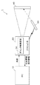
本願の実施形態1に係る情報処理システム1を、図1を参照して説明する。画像投影システム1は、パーソナルコンピュータ(PC10)と、ポインタ制御装置30を含むプロジェクタ20と、スクリーン40と、ポインタデバイス50と、から構成される。
(Embodiment 1)
An
PC10は、プロジェクタ20がスクリーン40上に投影すべき画像をプロジェクタ20に出力する計算機である。実施形態1では、PC10はアナログRGB端子やHDMI(登録商標)端子等の画像出力端子を用いて画像を外部出力する機能を備えたノートパソコンである。
The PC 10 is a computer that outputs an image to be projected on the
プロジェクタ20は、PC10が出力する画像をスクリーン40に投影する画像投影装置である。プロジェクタ20は、ポインタデバイス50から、ポインタデバイス50が投影画像上を指示する位置を示す位置情報と、ユーザがポインタデバイス50に対して行った操作についての情報(操作情報)と、を受信する。プロジェクタ20は、位置情報と投影画像の大きさ・形状とに基づいて内部のポインタ制御装置30が(手振れ補正して)定めたポインタの位置を、操作情報と合わせてPC10に伝達する。
The
スクリーン40は、プロジェクタ20が投影する光線を受け止めて画像を形成するための投影面として機能する幕である。
The
ポインタデバイス50は、スクリーン40上の投影画像上の部位を指示して、指示した部位の位置情報を取得する。位置情報とは、ポインタデバイス50が指示したスクリーン40上の位置に対応する、投影するための画像(投影用画像)上の指示座標(x、y)を示す情報である。ポインタデバイス50はボタン等の操作受付手段を備え、受け付けた操作の情報と、位置情報と、をプロジェクタ20に伝達する。操作受付手段が受け付ける操作の例として、例えばマウスの右クリックや左クリックに相当する操作がある。
The
ポインタデバイス50が指示座標を取得する方法は、ポインタデバイス50がスクリーン40上に赤外線レーザを照射し、カメラで赤外線レーザの位置を取得する等の既知の任意のスクリーン上の座標取得方法であってよいが、ここではポインタデバイス50が赤外線カメラを備え、プロジェクタ20が所定の間隔で投影する赤外線のグラデーション画像を撮影し、その強さから画像上の座標を取得するものとする。
The
プロジェクタ20がスクリーン40に投影する画像(投影用画像、画像PI1〜画像PI3)上で、ポインタ制御装置30がポインタをどのように制御されるかについて、図2を参照して説明する。
How the
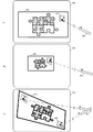
プロジェクタ20が、スクリーン40上に画像PI1を、歪み無く大きく投影した場合の手振れ補正の例を図2(a)に示す。
図2(a)では、ユーザはポインタデバイス50を用いてスクリーン40上の画像PI1の部位を指し示しており、その部位にポインタ(黒太矢印)が表示されている。ポインタデバイス50を持つユーザの手は、一定の幅でふるえている。
FIG. 2A shows an example of camera shake correction when the
In FIG. 2A, the user uses the
このとき、手振れによってポインタデバイス50がふるえることにより、ポインタが指し示す部位(指示位置)もある範囲で揺れ動く。ポインタ制御装置30は、所定の範囲での動きを手振れと判定し、その範囲での指示位置の変動をポインタの位置に反映させない。
PI1はスクリーン40上に大きく投影されているので、手振れによる指示位置のぶれが及ぶ範囲は、スクリーン40上の画像PI1に比して小さい。そのため、画像PI1上のアイコンや操作部位等を指し示す操作に手振れが与える影響は比較的小さい。そこで、ポインタ制御装置30は、手振れと判定する範囲(補正範囲、手振れ補正範囲)を、画像PI1の比較的小さい範囲(例えば部位A1の内部)に設定する。
At this time, when the
Since PI1 is largely projected on the
プロジェクタ20が、スクリーン40上に画像PI2を、歪みなく小さく投影した場合の手振れ補正の例を図2(b)に示す。
ユーザが図2(a)と同じ位置から、同じ量の手振れと共にPI2上の部位を指し示したとする(図2(b))。このとき、手振れによる指示位置のぶれが及ぶ範囲は、画像PI2に占める割合は、図2(a)よりも大きいため、手振れが操作に与える影響も大きい。
そのため、ポインタ制御装置30は、補正範囲を、画像PI2上の比較的大きい範囲(例えば部位A2の内部)に設定する。即ち、画像PI1と画像PI2とが同じ解像度を持つ場合には、部位A2は部位A1よりも面積(ピクセル数)が大きくなる。
FIG. 2B shows an example of camera shake correction when the
Suppose that the user points to a part on PI2 from the same position as in FIG. 2A together with the same amount of hand movement (FIG. 2B). At this time, the range in which the shake of the designated position due to the camera shake is larger than the ratio of the image PI2 in FIG. 2A, and thus the influence of the camera shake on the operation is large.
Therefore, the
プロジェクタ20が、スクリーン40に対して斜めから画像PI3を投影した結果、スクリーン40上で画像PI3が歪んでいる場合の手振れ補正の例を、図2(c)に示す。
ユーザが図2(a)及び(b)と同じ位置から、同じ量の手振れと共にスクリーン40上の画像PI3上の部位を指し示したとする。このとき、手振れによる指示位置のぶれが及ぶ範囲(手振れが操作に及ぼす影響)は、その部位が画像PI3上のどの位置にあるかによって異なる。
An example of camera shake correction when the image PI3 is distorted on the
Assume that the user points to a part on the image PI3 on the
図2(c)の例では、例えば部位A3の周辺では、歪みによって画像が大きく引きのばされているため、手振れによる指示位置のぶれが及ぶ範囲は相対的に小さく、手振れがユーザ操作に及ぼす影響も小さい。
一方、部位A4の周辺では、歪みによって画像が小さく縮小されてため、手振れによる指示位置のぶれがユーザ操作に及ぼす影響が部位A3の付近よりも大きくなる。
In the example of FIG. 2C, for example, in the vicinity of the part A3, the image is greatly extended due to distortion. Therefore, the range of movement of the indicated position due to camera shake is relatively small, and the camera shake affects the user operation. The impact is small.
On the other hand, in the vicinity of the part A4, the image is reduced to a small size due to the distortion, so that the influence of the shake of the designated position due to the camera shake on the user operation becomes larger than the vicinity of the part A3.
そこで、ポインタ制御装置30は、補正範囲を、部位A3のように画像PI3が歪みによって大きくのばされている部分では、画像PI3上の比較的小さい範囲(例えば部位A3の内部)に設定し、部位A4のように歪みによって縮小されている部分では、画像PI3上の比較的大きい範囲(例えば部位A4の内部)に設定する。
Therefore, the
次に、プロジェクタ20の構成を、図3を参照して説明する。プロジェクタ20は、入力部200と、A/Dコンバータ210と、表示制御部220と、発光制御部230と、ランプユニット240と、投影デバイス250と、光学レンズユニット260と、通信部270と、撮像部280と、出力部290と、ポインタ制御装置30と、から構成される。
Next, the configuration of the
入力部200は、アナログRGB端子やHDMI(登録商標)端子等の画像信号入力端子から構成され、PC10が出力する画像信号を受け付ける。
入力部200は、受け付けた画像信号をA/Dコンバータ210に伝達する。
The
The
A/Dコンバータ210は、入力部200から伝達された画像信号をデジタルの画像情報に変換し、表示制御部220に伝達する。
The A /
表示制御部220は、制御用CPU(Central Processing Unit)、作業用領域として用いられるRAM(Random Access Memory)、制御プログラム及び制御パラメータ等を記憶するEPROM(Erasable Programmable Read Only Memory)等から構成され、発光制御部230と投影デバイス250とを制御する。
表示制御部220は、A/Dコンバータ210から伝達された画像を、必要が有れば台形補正等の補正処理を施し、発光制御部230と投影デバイス250とを制御して投影画面に投影する。
The
The
発光制御部230は、表示制御部220から制御を受け、ランプユニット240を制御する制御回路である。
発光制御部230は、ランプユニット240に投影デバイス250が画像投影のために必要とするビーム(光線)を供給させる。
The light
The light
ランプユニット240は、発光制御部230から制御をうけて発光し、投影デバイス250にビームを供給する発光装置である。
The
投影デバイス250は、カラーホイール、DMD(Digital Micromirror Device)、等から構成されるプロジェクタの投影機能を担う装置であり、表示制御部220の制御に基づき、表示制御部220から伝達された画像を光線に変換し、光学レンズユニット260に伝達する。
なお、投影デバイス250は、上記構成に限らず、液晶パネルによって画像を投影する画像投影デバイス等の、既知の任意の画像投影デバイスであってよい。
The
The
光学レンズユニット260は、複数のレンズとレンズを所定の位置に移動させるモータとから構成される光学機器である。光学レンズユニット260は撮影デバイス250から伝達された光線をスクリーン40上に結像させる。
The
通信部270は、Bluetooth(登録商標)、無線LAN(Local Aria Network)、等の規格に準拠した通信デバイスである。通信部270は、ポインタデバイス50と通信して、ポインタデバイス50が指し示す位置を示す指示座標の情報と、操作情報とを順次受信する。通信部270は、受信した情報を順次ポインタ制御装置30の通信制御部340に伝達する。通信部270がポインタデバイス50と通信する方法は無線通信に限らず、USB(Universal Serial Bus)、パラレルポート等の有線の通信デバイスを用いて通信する構成も可能である。
The
撮像部280はレンズ、CCD(Charge Coupled Device Image Sensor)、等から構成され、スクリーン40上に投影された投影画像を撮影する撮像デバイスである。
撮像部280は、投影画像を撮影した撮像画像を、ポインタ制御装置30の撮像制御部310に伝達する。
The
The
出力部290は、LAN、USB、パラレルポート、等の規格に準拠した通信デバイスである。出力部290はポインタデバイス50が伝達するポインタデバイス50が指し示す投影画像上の部位を示す情報と、操作情報とをPC10に出力する。
The
ポインタ制御装置30は、物理的には、図4に示すように情報処理部301と、データ記憶部302と、プログラム記憶部303と、入出力部304と、内部バス307と、から構成される。
As shown in FIG. 4, the
情報処理部301は、CPU(Central Processing Unit)、DSP(Digital Signal Processing)、等から構成され、プログラム記憶部303に記憶されている制御プログラム308に従って、後述するポインタ制御装置30が実行する処理を実行する。
The
データ記憶部302は、RAM(Random Access Memory)等から構成され、情報処理部301の作業領域として用いられる。
The
プログラム記憶部303は、フラッシュメモリ、ハードディスク、等の不揮発性メモリから構成され、情報処理部301の動作を制御する制御プログラム308を記憶する。
なお、情報処理部301と、データ記憶部302と、プログラム記憶部303と、入出力部304と、は内部バス307によってそれぞれ接続され、情報の送信が可能である。
The
Note that the
入出力部304は外部機器との情報の入出力を制御するI/O部である。
入出力部304は、プロジェクタ20の通信部270、撮像部280等から入力されるデータを取得して情報処理部301に伝達する。また、入出力部304はプロジェクタ20の出力部290、外部機器と通信して情報処理部301の演算結果を出力する。
The input /
The input /
ポインタ制御装置30は、上記物理構成により、図3に示すように撮像制御部310と、正方画角補正量算出部320と歪み量算出部330とを含む画像処理部380と、通信制御部340と、補正範囲決定部350と、ポインタ位置決定部360と、記憶部370と、として機能する。
As shown in FIG. 3, the
撮像制御部310は、撮像部280を制御し、投影デバイス250が光学レンズユニット260を通してスクリーン40に投影した画像を撮影する。撮像制御部310は、撮影した画像を、画像処理部380に伝達する。
The
通信制御部340は、通信部270を制御し、ポインタデバイス50が伝達する位置情報(指示位置の座標)と、操作情報と、を取得する。通信制御部340は、取得した指示位置の座標と、操作情報と、をポインタ位置決定部360に伝達する。
The
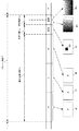
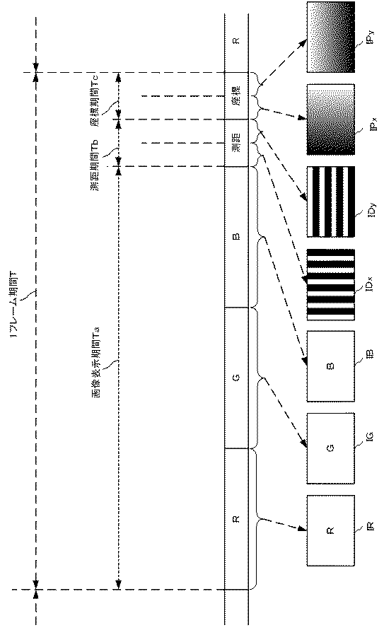
ここで、プロジェクタ20が1フレーム期間にスクリーン40に投影する投影画像を、図5を参照して時系列で説明する。
プロジェクタ20は、1フレーム期間T(例えば1/60秒)において、まず画像表示期間Taに、PC10から取得した画像の赤色成分(画像IR)と、緑色成分(画像IG)と、青色成分(画像IB)と、の画像を順次投影する。画像表示期間Taで画像IRと画像IGと画像IBとを投影することにより、プロジェクタ20はPC10から取得した投影用画像をスクリーン40に投影する。
Here, a projection image projected on the
In one frame period T (for example, 1/60 seconds), the
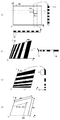
次に、プロジェクタ20は投影画像の形状・大きさを測定するための測距用画像(画像IDx及び画像IDy)を投影する(測距期間Tb)。測距期間Tbでは、まず横方向の距離を測るための画像IDxを投影し、縦方向の距離を測るための画像IDyを投影する。
画像IDxは一定間隔の縦縞模様、画像IDy一定間隔の横縞模様である。画像IDx及び画像IDyは、スクリーン40上の投影領域の大きさ・形状に対応する縞模様としてスクリーン40上に投影される。スクリーン40上で投影領域が台形に歪んでいると、画像IDx及び画像IDyも図6(b)及び図6(c)のように歪んで投影される。画像IDx及び画像IDyは任意の色の縞模様の画像であってよいが、ここでは赤外線画像であるとする。
Next, the
The image IDx is a vertical stripe pattern with a constant interval and a horizontal stripe pattern with a constant interval of the image IDy. The image IDx and the image IDy are projected on the
次に、プロジェクタ20はポインタデバイス50が投影画像上で指示座標を取得するための画像(画像IPx及び画像IPy)を投影する(座標期間Tc)。画像IPxは、光度が投影用画像上で横のグラデーションになっており、ある部位の光度とその部位のx座標とが対応する。画像IPxは、光度が投影用画像上で縦のグラデーションになっており、ある部位の光度とその部位のy座標とが対応する。
Next, the
ポインタデバイス50は、カメラを用いて画像IPxの光度と画像IPyの光度を取得して、自身が指し示している部位が投影画像上のどの部位にあたるか、そのx座標とy座標(指示座標)を取得する。
The
撮像制御部310は、撮像部280を用いて、画像IDxと画像IDyを撮影し、当該撮影画像を画像処理部380に伝達する。
The
通信制御部340は、画像IPxと画像IPyとの光度からポインタデバイス50が取得した指示座標の情報と、ユーザがポインタデバイス50に対して行った操作(右クリック、左クリック等)を示す操作情報と、を通信部270を用いて取得する。
The
図3に戻って説明を続ける。画像処理部380は、撮像制御部310から伝達された撮影画像から、画像IDxと画像IDyとの撮影画像を抽出する。そして、正方画角補正量算出部320と歪み量算出部330は、抽出した画像IDxと画像IDyの撮影画像から、手振れ補正の補正範囲を定めるパラメータ(補正パラメータ)を算出する。補正パラメータの内容及び補正パラメータを算出する処理については後述する。
画像処理部380は、算出した補正パラメータを補正範囲決定部350に伝達する。
Returning to FIG. 3, the description will be continued. The
The
補正範囲決定部350は、画像処理部380から伝達された補正パラメータと、記憶部370の履歴記憶部3710に記憶された基準位置の座標と、から手振れ補正範囲を決定する。
The correction
画像処理部380の各部が補正パラメータを算出し、補正範囲決定部350が手振れ補正範囲を決定する処理について、図6を参照して説明する。図6(a)は、所定の距離から所定の設定に基づきスクリーン40に歪み無く投影された基準投影画像BIである。基準投影画像BIを投影する設定を、基準投影設定と呼ぶ。基準投影画像BI上では、基準ゆがみ補正範囲SA(投影用画像上で縦Cbvピクセル、横Cbhピクセル、の大きさを持つ長方形)が図6(a)のように表示される。なお、基準ゆがみ補正範囲は、正方形であっても良い。
A process in which each unit of the
そして、プロジェクタ20が基準投影設定で画像を投影した場合、画像IDxの縦縞は、スクリーン40上で基準幅Hbをもつ縞として投影される。また、画像IDxの縦縞は、スクリーン40上で基準幅Vbをもつ縞として投影される。
When the
基準ゆがみ補正範囲SAの縦の大きさCbv、横の大きさCbh,基準幅Hb,基準幅Vb、は後述する記憶部370の設定記憶部3720に定数として予め記憶されている。
The vertical size Cbv, the horizontal size Cbh, the reference width Hb, and the reference width Vb of the reference distortion correction range SA are stored in advance as constants in the setting
基準投影設定以外の投影設定で、歪んで投影された場合の投影画面を図6(b)〜(d)に示す。このとき、画像IDxの縦縞は、スクリーン40上で最大幅Hlから最小幅Hsをもつ縞として投影される(図6(b))。また、画像IDyの横縞は、スクリーン40上で最大幅Vlから最小幅Vsをもつ縞として投影される(図6(c))。画像処理部380は、画像IDyから、原点O側の縞の幅(ここでは最小幅Vs)と原点からy軸上で+側に最も遠い縞の幅(ここでは最大幅Vl)を求める。また、画像IDxから、原点O側の縞の幅(ここでは最小幅Hs)と原点からx軸で+側に最も遠い縞の幅(ここでは最大幅Hl)と、を求める。なお、上記の最大幅Hl及び最小幅Hsは、投影画像上の(横方向の)中央部に位置する短冊状の領域において取得する。この短冊状の領域の幅は、領域内でのひずみの影響を無視しうる程度に小さいとする。最大幅Vlと最小幅Vsも、方向を変えて同様に取得するものとする。
FIGS. 6B to 6D show projection screens when projection is performed with distortion other than the reference projection setting. At this time, the vertical stripes of the image IDx are projected on the
正方画角補正量算出部320は、取得した最小幅Hsと基準幅Hbとから、水平の画角割合Zhを算出する。水平の画角割合Zhは、その画像全体が水平方向にどの程度引き延ばされているかを表す数値である。
水平の画角割合Zhは、例えば計算式(1)を用いて算出する。
Zh=Hs/Hb …(1)
The square field angle correction
The horizontal field angle ratio Zh is calculated using, for example, the calculation formula (1).
Zh = Hs / Hb (1)
正方画角補正量算出部320は、取得した最小幅Vsと基準幅Vbとから、垂直の画角割合Zvを算出する。垂直の画角割合Zhは、その画像全体が垂直方向にどの程度引き延ばされているかを表す数値である。
垂直の画角割合Zvは、例えば計算式(2)を用いて算出する。
Zv=Vs/Vb …(2)
The square field angle correction
The vertical field angle ratio Zv is calculated using, for example, the calculation formula (2).
Zv = Vs / Vb (2)
なお、水平の画角割合Zhや垂直の画角割合Zvを求める方法は式(1)、(2)に限らず、例えばHs(Vs)をHb(Vb)の二乗で除算する、Hs(Vs)とHb(Vb)とを引数とする所定の参照テーブルを用いて決定する、Hl(Vl)をHb(Vb)で除算する、等の任意の方法を用いて求めても良い。 The method for obtaining the horizontal field angle ratio Zh and the vertical field angle ratio Zv is not limited to the equations (1) and (2). For example, Hs (Vs) is divided by the square of Hb (Vb). ) And Hb (Vb) may be determined by using an arbitrary method such as determining using a predetermined reference table having arguments as arguments, and dividing Hl (Vl) by Hb (Vb).
さらに、正方画角補正量算出部320は、算出した水平の画角割合Zhと標準補正量Cbhから水平の正方補正量C0hを、算出する。
水平の正方補正量C0hは、手振れ補正範囲の水平方向の大きさを決定するパラメータの一つであり、画像全体が横方向に引き延ばされている割合が大きいほど大きくなる。
水平の正方補正量C0hは、例えば式(3)を用いて算出することができる。
C0h=Cbh・Zh …(3)
同様に、算出した垂直の画角割合Zvと標準補正量Cbvとから、垂直の正方補正量C0vを式(4)を用いて算出できる。
C0v=Cbv・Zv …(4)
Further, the square field angle correction
The horizontal square correction amount C0h is one of the parameters for determining the horizontal size of the camera shake correction range, and increases as the ratio of the entire image stretched in the horizontal direction increases.
The horizontal square correction amount C0h can be calculated using, for example, Expression (3).
C0h = Cbh · Zh (3)
Similarly, a vertical square correction amount C0v can be calculated from the calculated vertical angle of view ratio Zv and the standard correction amount Cbv using Equation (4).
C0v = Cbv · Zv (4)
なお、水平の正方補正量C0hや垂直の正方補正量C0vを求める方法は式(3)、(4)に限らず、例えばCbh(Cbv)とZh(Zv)の二乗同士の乗算式や、Cbh(Cbv)とZh(Zv)とを引数とする所定の参照テーブルを用いて決定する、等の任意の方法を用いて求めても良い。 Note that the method for obtaining the horizontal square correction amount C0h and the vertical square correction amount C0v is not limited to the equations (3) and (4). For example, a multiplication equation of squares of Cbh (Cbv) and Zh (Zv), You may obtain | require using arbitrary methods, such as determining using the predetermined | prescribed reference table which uses (Cbv) and Zh (Zv) as an argument.
歪み量算出部330は、最大幅HI及び最小幅Hsとから、水平の歪み割合Khを算出する。水平の歪み割合Khは、画像がどの程度水平方向に歪んでいるか、その歪みの程度を示す係数である。ここでは、投影画像が歪みなく投影されている場合は1と等しく、原点O(ここでは左側)の部分が右側よりも画像が引き延ばされている場合に1より大きくなり、逆の場合は1より小さくなる係数である。
水平の歪み割合Khは例えば式(5)を用いて算出できる。
Kh=Hl/Hs …(5)
さらに、最大幅Vlと最小幅Vsとから、垂直の歪み割合Kvを式(6)を用いて算出する。垂直の歪み割合Kvは、原点O(ここでは下側)の部分が上側よりも画像が引き延ばされている場合に1より大きくなり、逆の場合は1より小さくなる係数である。
Kv=Vl/Vs …(6)
The distortion
The horizontal distortion ratio Kh can be calculated using, for example, Expression (5).
Kh = Hl / Hs (5)
Further, the vertical distortion ratio Kv is calculated from the maximum width Vl and the minimum width Vs using Expression (6). The vertical distortion ratio Kv is a coefficient that is larger than 1 when the image is stretched from the upper side at the origin O (lower side in this case), and smaller than 1 in the opposite case.
Kv = Vl / Vs (6)
なお、水平の歪み割合Khや垂直の歪み割合Kvを求める方法は式(5)、(6)に限らず、例えばHl(Vl)をHs(Vs)の二乗で除算する式や、Hl(Vl)とHs(Vs)とを引数とする所定の参照テーブルを用いる、等の任意の方法を用いて求めても良い。 Note that the method for obtaining the horizontal distortion ratio Kh and the vertical distortion ratio Kv is not limited to Expressions (5) and (6). For example, Hl (Vl) is divided by the square of Hs (Vs), or Hl (Vl ) And Hs (Vs) may be used to obtain the values using an arbitrary method such as a predetermined reference table.
画像処理部380は、正方画角補正量算出部320が算出した水平の正方補正量C0hと垂直の正方補正量C0vと、歪み算出部330が算出した水平の歪み割合Khと垂直の歪み割合Kvと、を補正範囲決定部350に伝達する。
The
補正範囲決定部350は、画像処理部380から、水平の正方補正量C0hと垂直の正方補正量C0vと、水平の歪み割合Khと垂直の歪み割合Kvと、を伝達されると、さらに記憶部370の履歴記憶部3710に記憶された基準位置Pの座標(Px、Py)を取得する。ここでは、基準位置Pは現在のポインタの位置である。
図6(d)は、記憶部370の履歴記憶部3710に記憶された基準位置Pが座標(Px,Py)に位置する例を示している。ここで、画像PI4の解像度は水平方向にGhピクセル、垂直方向にGvピクセル、である。なお、Pxは基準位置P(t)が原点OからPxピクセル分x軸に方向にずれた位置にあること、Pyは基準位置Pが原点OからPyピクセル分y軸に方向にずれた位置にあること、をそれぞれ示す。
When the correction
FIG. 6D shows an example in which the reference position P stored in the
補正範囲決定部350は、式(7)を用いて水平方向の補正量Chを、式(8)を用いて垂直方向の補正量Cvを算出する。
Ch=C0h・Kh・(Px+Gh)/Gh …(7)
Cv=C0v・Kv・(Py+Gv)/Gv …(8)
The correction
Ch = C0h · Kh · (Px + Gh) / Gh (7)
Cv = C0v · Kv · (Py + Gv) / Gv (8)
なお、ここでは水平方向の補正量Ch及び垂直方向の補正量Cvを上記式(1)〜(8)で求めたが、Ch及びCvを算出する方法はこれに限られず、投影画面上で基準位置において投影用画像の一ピクセル(あるいは所定数のピクセル)が大きく引き延ばされているほど補正量Ch及び補正量Cvが小さくなるようなその他の算定方法を用いて補正量Cv及び補正量Chを求めても良い。 Here, the horizontal correction amount Ch and the vertical correction amount Cv are obtained by the above formulas (1) to (8). However, the method of calculating Ch and Cv is not limited to this, and the reference value on the projection screen is used. The correction amount Cv and the correction amount Ch are calculated using other calculation methods in which the correction amount Ch and the correction amount Cv become smaller as one pixel (or a predetermined number of pixels) of the projection image is greatly extended at the position. You may ask for.
補正範囲決定部350は、投影用画像上の基準位置Pを中心とする横Chピクセル、縦Cvピクセルの領域を手振れ補正範囲(補正範囲)として定め、当該領域の情報をポインタ位置決定部360に伝達する。
The correction
図3にもどって説明を続ける。ポインタ位置決定部360は、通信制御部340から伝達された現在の指示座標と操作情報と、補正範囲決定部350から伝達された手振れ補正範囲と、に基づいて新たなポイント位置を定める。
そして、更新した座標をあらたな基準位置Pとして、記憶部370の履歴記憶部3710に記憶する。
Returning to FIG. 3, the description will be continued. The pointer
Then, the updated coordinates are stored in the
ポインタ位置決定部360は、新たなポインタ位置の座標と、操作情報と、を出力部290を用いてPC10に伝達する。
The pointer
記憶部370は、ポインタ制御装置30の記憶部370を除く各部がポインタ制御処理のために用いるプログラム及び情報を記憶する記憶装置である。記憶部370は、ポインタ制御装置30の記憶部370を除く各部からのコマンドに応答して、記憶する情報を供給する。
記憶部370は、ポインタ位置決定部360を始めとするポインタ制御装置30の記憶部370を除く各部の処理結果を記憶する。
記憶部370は、履歴記憶部3710と、設定記憶部3720と、を含む。
The
The
履歴記憶部3710は、基準位置Pの座標を含む、ポインタの座標の履歴を記憶する。設定記憶部3720は、基準ゆがみ補正範囲SAの縦の大きさCbv、横の大きさCbh,基準幅Hb,基準幅Vb、等のポインタ制御処理に必要な各種設定情報を記憶する。
The
次に、ポインタ制御装置30が実行するポインタ制御処理1について、図7を参照して説明する。
ポインタ制御装置30は、プロジェクタ20が投影画像を投影し、ポインタデバイス50から指示座標を伝達されると、図7のポインタ制御処理1を開始する。
Next,
The
ポインタ制御処理1では、まず撮像制御部310が撮像部280を用いて画像IDx及び画像IDyを撮影する。そして、画像処理部380が縞のパターンを抽出する(ステップS101)。
In the
画像処理部380は、取得したパターンから画像IDxの縦縞の最大幅Hlと最小幅Hsと、画像IDyの最大幅Vlと最小幅Vsと、を取得する(ステップS102)。
The
ついで、正方画角補正量算出部320が、式(1)と式(2)とを用いて水平の画角割合Zhと垂直の画角割合Zvとを算出する(ステップS103)。
Next, the square field angle correction
そして、歪み量算出部330が、式(5)と式(6)とを用いて、水平の歪み割合Khと垂直の歪み割合Kvとを算出する(ステップS104)。
Then, the distortion
次に、水平の画角割合Zhと垂直の画角割合Zvと、水平の歪み割合Khと垂直の歪み割合Kvと、を用いて手振れ補正範囲決定処理1を実行する(ステップS105)。
Next, camera shake correction
ステップS105で実行される手振れ補正範囲決定処理1を、図8を用いて説明する。手振れ補正範囲決定処理1では、まず正方画角補正量算出部320が式(3)を用いて水平の正方補正量C0hを、式(4)を用いて垂直の正方補正量C0vを、それぞれ算出する(ステップS201)。
The camera shake correction
次に、補正範囲決定部350は、記憶部370の履歴記憶部3710に記憶された基準位置Pの座標(Px、Py)を取得する(ステップS202)。
Next, the correction
ステップS202で基準位置Pの座標を取得すると、補正範囲決定部350は、式(7)を用いて水平方向の補正量Chを、式(8)を用いて垂直方向の補正量Cvと、それぞれ算出する(ステップS203)。
When the coordinates of the reference position P are acquired in step S202, the correction
補正範囲決定部350は、基準位置Pを中心とする横Chピクセル、縦Cvピクセルの領域を手振れ補正範囲の領域として定め(ステップS204)、手振れ補正範囲決定処理1を終了する。
The correction
図7に戻り、ステップS106では通信制御部340が現在の指示座標を取得する(ステップS106)。
Returning to FIG. 7, in step S106, the
そして、ポインタ位置決定部360は、現在の指示位置が手振れ補正範囲に含まれるか判別する(ステップS107)。
指示位置が手振れ補正範囲の領域内であると判別すると(ステップS107;YES)、その範囲の動きは手振れであるとの推測できるので、ポインタ位置を更新せず、基準位置をポインタ位置としてPC10に伝達し、処理はステップS101にもどる。
Then, the pointer
If it is determined that the designated position is within the range of the camera shake correction range (step S107; YES), it can be estimated that the movement in the range is a camera shake, so the pointer position is not updated and the
一方、指示位置が手振れ補正範囲の領域外であると判別すると(ステップS107;NO)、そのポインタデバイス50の動作は手振れではないとの推測のもと、新たな指示位置をポインタの位置とする(ステップS108)。
ステップS108では、更新したポインタの位置をあらたな基準位置Pとして、記憶部370の履歴記憶部3710に記憶する。また、新たなポインタ位置をPC10に伝達する。
On the other hand, if it is determined that the designated position is outside the range of the camera shake correction range (step S107; NO), the new designated position is set as the pointer position on the assumption that the operation of the
In step S108, the updated pointer position is stored in the
そして、新たな基準位置を用いて処理をステップS101から繰り返す。 Then, the process is repeated from step S101 using the new reference position.
本実施形態のポインタ制御装置30によれば、上記処理によって直前のポインタ位置である基準位置から所定の範囲での指示位置の動きを手振れと判定し、ポインタ位置を補正することができる。また、手振れ補正と判定する範囲を、基準位置で投影用画像がどの程度引き延ばされているか、に応じて自動的に定めることが出来るため、実際の投影画像の大きさに基づいてユーザのニーズに合致した手振れ補正を実行することが出来る。そのため、ユーザがポインタデバイス50を用いて投影画像上で操作するに際し、使い勝手がよい。また、ユーザが自ら補正パラメータを設定する等の煩雑な操作をせずとも手振れ補正を実行できる。
According to the
また、本実施形態のポインタ制御装置30によれば、手振れ補正と判定する範囲を、従来台形補正に用いられている縞のパターンと、これを撮影する撮像部と、を用いて算出する正方画角と歪み率とを用いて自動的に定めることができる。そのため、ユーザは特別の手振れ設定処理等の煩雑な操作を実行する必要の無い、利便性の高い手振れ補正機能を提供できる。また、手振れ補正のための特別な画像処理を実行する必要がない。
また、従来の技術による手振れ補正では、キャリブレーションによって取得したパラメータを投影画像全体に適用するため、画面が歪んでいた場合などでも同一の補正パラメータを用いて手振れ補正を実行するため、部位によって補正パラメータを変える等の柔軟な手振れ補正が実現できなかった。そのため、パラメータをユーザ操作に基づいて定めても、部位によって手振れ補正のパラメータがユーザのニーズとずれてしまうという問題があった。本実施形態のポインタ制御装置30によれば、現在の基準位置においてどの程度画像が引き延ばされているか等を鑑みて算出されたパラメータを用いて手振れ補正が実行できるため、ユーザのニーズにあった手振れ補正が実現できる。
In addition, according to the
In addition, in the camera shake correction according to the conventional technique, since the parameters acquired by calibration are applied to the entire projection image, the camera shake correction is performed using the same correction parameters even when the screen is distorted. Flexible camera shake correction such as changing parameters could not be realized. Therefore, even if the parameter is determined based on the user operation, there is a problem that the camera shake correction parameter is different from the user's needs depending on the part. According to the
なお、上記実施形態1では、正方画角と歪み率とを、フレームごとに取得して逐一補正パラメータを算出した。実施形態1の変形例として、一度取得した補正パラメータを記憶部370に記憶し、フレーム毎に記憶した補正パラメータを用いて手振れ補正処理を実行する構成も可能である。
このとき、補正パラメータは、台形補正の設定の更新やリセットボタンの押下などのイベントに応答して再度算出するとしてもよい。
In the first embodiment, the square angle of view and the distortion rate are acquired for each frame, and the correction parameters are calculated one by one. As a modification of the first embodiment, it is possible to store the correction parameter once acquired in the
At this time, the correction parameter may be calculated again in response to an event such as updating of the keystone correction setting or pressing of the reset button.
また、上記実施形態1では、歪み量算出部330は、水平方向の歪み割合Khと垂直方向の歪み割合Kvとを歪み量として算出し、補正範囲決定部350に伝達した。実施形態1の変形例として、歪み量算出部330は、画像IDxの原点側の縞(最も左側の縞)の幅Hllと、原点からx軸の+の方向に最も遠い縞(最も右側の縞)の幅Hlrと、の組み合わせを水平方向の歪み量として補正範囲決定部350に伝達しても良い。同様に、原点からy軸の+の方向に最も遠い縞(最も上側の縞)Vlhと、原点側の縞(最も下側の縞)の幅Vslの幅と、の組み合わせを垂直方向の歪み量として補正範囲決定部350に伝達する。
In the first embodiment, the distortion
このとき、補正範囲決定部350は、例えば次の式(9)を用いて水平方向の補正量Chを算出する。
At this time, the correction
式(9)の(Gh−Px)/Ghは、指示座標Pxが画像の原点O側(左側)にあるほど大きくなる係数、Hll/(Hll+Hlr)は画像の左側が引き伸ばされているほど大きくなる係数である。また、Px/Ghは指示座標Pxが画像の原点から+側(右側)にあるほど多くなる係数、Hlr/(Hll+Hlr)は、画像の右側が引き伸ばされているほど大きくなる係数である。 (Gh−Px) / Gh in equation (9) is a coefficient that increases as the designated coordinate Px is closer to the origin O side (left side) of the image, and Hll / (Hll + Hlr) increases as the left side of the image is stretched. It is a coefficient. Px / Gh is a coefficient that increases as the designated coordinate Px is on the + side (right side) from the origin of the image, and Hlr / (Hll + Hlr) is a coefficient that increases as the right side of the image is stretched.
(Gh−Px)/Ghは、指示座標Pxが投影用画像でどの程度原点側にあるか、をあらわす任意の係数と置換可能である。例えば、(Gh−Px)2/Gh2等と置換することが出来る。
Px/Ghについても同様である。
(Gh−Px) / Gh can be replaced with an arbitrary coefficient representing how much the designated coordinates Px are on the origin side in the projection image. For example, it is possible to replace the (Gh-Px) 2 / Gh 2 and the like.
The same applies to Px / Gh.
また、Hll/(Hll+Hlr)は、投影用画像の原点側が引き伸ばされている程度を表す任意の係数と置換可能である。例えば、係数Hll2/(Hll+Hlr)2と置換することが出来る。
Hlr/(Hll+Hlr)についても同様である。
Further, Hll / (Hll + Hlr) can be replaced with an arbitrary coefficient representing the degree to which the origin side of the projection image is stretched. For example, the coefficient Hll 2 / (Hll + Hlr) 2 can be substituted.
The same applies to Hlr / (Hll + Hlr).
また、補正範囲決定部350は、例えば次の式(10)を用いて垂直方向のCvと算出する。
In addition, the correction
式(9)の(Gv−Py)/Gvは、指示座標Pyが画像の原点O側(下側)にあるほど大きく成る係数、Hll/(Hll+Hlr)は画像の下側が引き伸ばされているほど大きくなる係数である。また、Px/Ghは指示座標Pxが画像の原点から+側(右側)にあるほど大きく成る係数、Hlr/(Hll+Hlr)は、画像の右側が引き伸ばされているほど大きくなる係数である。
式(10)についても、式(9)と同様に上記係数を置換することが出来る。
In equation (9), (Gv−Py) / Gv is a coefficient that increases as the designated coordinate Py is closer to the origin O side (lower side) of the image, and Hll / (Hll + Hlr) is larger as the lower side of the image is stretched. Is a coefficient. Px / Gh is a coefficient that increases as the designated coordinate Px is on the + side (right side) from the origin of the image, and Hlr / (Hll + Hlr) is a coefficient that increases as the right side of the image is stretched.
In the equation (10), the coefficient can be replaced as in the equation (9).
(実施形態2)
次に、本発明の実施形態2について説明する。
実施形態2に係る画像投影システム2は、プロジェクタ21が現在のポインタ位置(基準位置)を中心とした基準図形をスクリーン40上に投影し、当該スクリーン上の基準図形の大きさに基づいて、ポインタ制御装置31が手振れ補正範囲を決定する事を特徴とする。
(Embodiment 2)
Next, Embodiment 2 of the present invention will be described.
In the image projection system 2 according to the second embodiment, the projector 21 projects a reference graphic centered on the current pointer position (reference position) onto the
実施形態2に係る画像投影システム2は、実施形態1に係る画像投影システム1と比して、プロジェクタが所定の期間、ポインタ位置を中心とする所定図形を投影し、かつポインタ制御装置31を含むプロジェクタ21であることが異なる。その他の構成は実施形態1に係る画像投影システム1と同じである。
Compared with the
実施形態2に係るプロジェクタ21及びポインタ制御装置31の構成を、図9を参照して説明する。
プロジェクタ21は、表示制御部(表示制御部221)の機能と、ポインタ制御装置(ポインタ制御装置31)の機能が異なる以外はプロジェクタ20(図2)と同じ構成を持つ。
The configurations of the projector 21 and the
The projector 21 has the same configuration as the projector 20 (FIG. 2) except that the function of the display control unit (display control unit 221) is different from the function of the pointer control device (pointer control device 31).
表示制御部221は、ポインタ制御装置31のポインタ位置決定部361からの指示に基づいて、投影デバイス250にポインタ位置を中心とする所定画像(基準図形)を所定期間スクリーン40に投影させる。ここでは、基準図形は投影用画像上では20ピクセル×20ピクセルの正方形とする。
The
ここで、プロジェクタ21が1フレーム期間にスクリーン40に投影する投影画像を、図10を参照して時系列で説明する。
プロジェクタ21は、測距期間Tbに、現在のポインタ位置を中心とする20ピクセル×20ピクセルの正方形SBを含む測距画像IDを投影する。その他の投影画像は、プロジェクタ20が投影する画像(図5)と同様である。
Here, a projection image projected on the
The projector 21 projects a distance measurement image ID including a square SB of 20 pixels × 20 pixels centered on the current pointer position during the distance measurement period Tb. Other projected images are the same as the images projected by the projector 20 (FIG. 5).
次に、ポインタ制御装置31が実行するポインタ制御処理2について、図11を参照して説明する。
ポインタ制御装置31は、プロジェクタ21が投影画像を投影し、ポインタデバイス50から指示位置を伝達されると、図11のポインタ制御処理2を開始する。
Next, pointer control processing 2 executed by the
The
ポインタ制御処理2では、まず現在のポインタの指示位置を中心として、基準図形SBとその配置を表示制御部221に伝達する。表示制御部221は、測距期間Tbに基準図形SBを含む画像IDを表示する(ステップS301)。
In the pointer control process 2, first, the reference graphic SB and its arrangement are transmitted to the
そして、撮像制御部310が撮像部280を用いて画像IDを撮影する。そして、画像処理部381が画像IDから基準図形SBを抽出(取得)する(ステップS302)。
Then, the
画像処理部381は、抽出した基準図形SBの高さHと、幅Wを取得する(ステップS303)。 The image processing unit 381 acquires the height H and the width W of the extracted reference graphic SB (step S303).
そして、画像処理部381は基準図形SBの高さHと、幅Wと、を用いて手振れ補正範囲決定処理2を実行する(ステップS304)。 Then, the image processing unit 381 executes the camera shake correction range determination process 2 using the height H and the width W of the reference graphic SB (step S304).
ステップS304で実行される手振れ補正範囲決定処理2を、図12を用いて説明する。手振れ補正範囲決定処理2では、まず図8の手振れ補正範囲決定処理1のステップS202と同様に基準位置の座標を取得する(ステップS401)。
次に、補正量算出部321が、式(11)を用いて水平方向の補正量Chを、式(12)を用いて垂直方向の補正量Cvを算出する(ステップS402)。
Ch=CSw・W/SW …(11)
Cv=CSh・H/SH …(12)
ただし、SWは基準投影設定で投影された場合の基準図形の横幅、SHは基準投影設定で投影された場合の基準図形の高さである。
CSwは基準投影設定で投影された場合の手振れ補正範囲の幅(単位:ピクセル)、CShは基準投影設定で投影された場合の手振れ補正範囲の高さ(単位:ピクセル)である。CSw、CSh、SW、SH、の各数値は記憶部370の設定記憶部3720に記憶されている。
The camera shake correction range determination process 2 executed in step S304 will be described with reference to FIG. In the camera shake correction range determination process 2, first, the coordinates of the reference position are acquired in the same manner as in step S202 of the camera shake correction
Next, the correction
Ch = CSw · W / SW (11)
Cv = CSh · H / SH (12)
However, SW is the width of the reference figure when projected with the reference projection setting, and SH is the height of the reference figure when projected with the reference projection setting.
CSw is the width (unit: pixel) of the camera shake correction range when projected with the reference projection setting, and CSh is the height (unit: pixel) of the camera shake correction range when projected with the reference projection setting. The numerical values of CSw, CSh, SW, and SH are stored in the setting
ステップS402で補正量を算出すると、実施形態1に係る手振れ補正範囲決定処理1のステップS204(図8)と同様に手振れ補正範囲を決定する(ステップS403)。
When the correction amount is calculated in step S402, the camera shake correction range is determined similarly to step S204 (FIG. 8) of the camera shake correction
図11に戻って、ステップS304が終わると、実施形態1にポインタ制御処理1のステップS106〜ステップS108(図7)と同様に新たなポインタ位置を定める処理を実行する(ステップS305〜ステップS307)。
Returning to FIG. 11, when step S304 is completed, processing for determining a new pointer position is executed in the same manner as in step S106 to step S108 (FIG. 7) of
ポインタ制御処理2では、ステップS307で新たなポインタ位置を定め、基準位置を更新した後に、当該新たな基準位置を中心として基準図形を画像IDに配置し、当該画像IDを表示制御部221に伝達する(ステップS308)。そして、次のフレームでは当該新たな画像IDに基づき手振れ補正範囲を決定する。
In the pointer control process 2, a new pointer position is determined in
実施形態2に記載のポインタ制御装置31によれば、縦縞と横縞とを取得して補正量を定める処理を行わずに補正量を決定し、手振れ補正を実現することが出来るため、必要となる処理用が少なくて済む。
According to the
(変形例)
以上、本発明の実施例について説明したが、本発明の実施形態は上記実施形態1乃至2に限定されず、下記のような変形が可能である。
(Modification)
As mentioned above, although the Example of this invention was described, embodiment of this invention is not limited to the said
例えば、上記実施形態1乃至2では、手振れ補正領域は長方形であったが、手振れ補正範囲は円形、楕円形、三角形、等であってもよい。
円形とした場合は、手振れ補正範囲の半径を水平方向の補正量Chと垂直方向の補正量Cvとの平均としてよい。
For example, in the first and second embodiments, the camera shake correction area is a rectangle, but the camera shake correction range may be a circle, an ellipse, a triangle, or the like.
In the case of a circular shape, the radius of the camera shake correction range may be an average of the horizontal correction amount Ch and the vertical correction amount Cv.
また、上記実施形態1乃至2では、補正範囲であった場合にポインタを移動しないとしたが、補正範囲内にあった場合は、移動速度を小さくする構成も可能である。このとき、基準位置は新たなポインタ位置で更新するとしても良いし、補正範囲にある期間は基準位置を更新しないとしても良い。 In the first and second embodiments, the pointer is not moved when it is within the correction range. However, when it is within the correction range, a configuration in which the moving speed is reduced is also possible. At this time, the reference position may be updated with a new pointer position, or the reference position may not be updated during a period within the correction range.
また、情報処理部301、データ記憶部302、プログラム記憶部303、入出力部304、等から構成されるポインタ制御装置30(ポインタ制御装置31)のための処理を行う中心となる部分は、専用のシステムによらず、通常のコンピュータシステムを用いて実現可能である。たとえば、前記の動作を実行するためのコンピュータプログラムを、コンピュータが読み取り可能な記録媒体(フレキシブルディスク、CD−ROM、DVD−ROM等)に格納して配布し、当該コンピュータプログラムをコンピュータにインストールすることにより、前記の処理を実行する情報端末を構成してもよい。また、インターネット等の通信ネットワーク上のサーバ装置が有する記憶装置に当該コンピュータプログラムを格納しておき、通常のコンピュータシステムがダウンロード等することで情報処理装置を構成してもよい。
In addition, a central part that performs processing for the pointer control device 30 (pointer control device 31) including the
また、ポインタ制御装置30(ポインタ制御装置31)の機能を、OS(オペレーティングシステム)とアプリケーションプログラムの分担、またはOSとアプリケーションプログラムとの協働により実現する場合などには、アプリケーションプログラム部分のみを記録媒体や記憶装置に格納してもよい。 In addition, when the function of the pointer control device 30 (pointer control device 31) is realized by sharing the OS (operating system) and the application program, or in cooperation with the OS and the application program, only the application program portion is recorded. You may store in a medium or a memory | storage device.
また、搬送波にコンピュータプログラムを重畳し、通信ネットワークを介して配信することも可能である。たとえば、通信ネットワーク上の掲示板(BBS:Bulletin Board System)に前記コンピュータプログラムを掲示し、ネットワークを介して前記コンピュータプログラムを配信してもよい。そして、このコンピュータプログラムを起動し、OSの制御下で、他のアプリケーションプログラムと同様に実行することにより、前記の処理を実行できるように構成してもよい。 It is also possible to superimpose a computer program on a carrier wave and distribute it via a communication network. For example, the computer program may be posted on a bulletin board (BBS: Bulletin Board System) on a communication network, and the computer program may be distributed via the network. The computer program may be started and executed in the same manner as other application programs under the control of the OS, so that the above-described processing may be executed.
また、上記ポインタ制御装置30(ポインタ制御装置31)が実行する処理の一部を、ポインタ制御装置30(ポインタ制御装置31)とは独立したコンピュータを用いて実現しても良い。 Moreover, you may implement | achieve a part of process which the said pointer control apparatus 30 (pointer control apparatus 31) performs using the computer independent of the pointer control apparatus 30 (pointer control apparatus 31).
以上、本発明の好ましい実施形態について説明したが、本発明は係る特定の実施形態に限定されるものではなく、本発明には、特許請求の範囲に記載された発明とその均等の範囲が含まれる。以下に、本願出願の当初の特許請求の範囲に記載された発明を付記する。 As mentioned above, although preferable embodiment of this invention was described, this invention is not limited to the specific embodiment which concerns, This invention includes the invention described in the claim, and its equivalent range It is. Hereinafter, the invention described in the scope of claims of the present application will be appended.
(付記1)
投影面上に投影するための画像である投影用画像上の、ポインタデバイスが指示する位置を示す指示座標を順次取得する指示座標取得部と、
前記投影用画像上の基準位置を定める基準位置定義部と、
前記投影用画像が前記投影面に投影される態様である投影態様を取得する投影態様取得部と、
前記基準位置定義部が定めた基準位置と、前記投影態様取得部が取得した投影態様と、に基づいて前記指示座標取得部が取得した指示座標の変化が手振れによるものか否かを判別する判別基準を定める判別基準定義部と、
前記指示座標取得部が取得した指示座標が変化すると、前記判別基準定義部が定めた判別基準を用いて当該変化が手振れによるものか否か判別し、当該判別結果と、前記基準位置定義部が定めた基準位置と当該変化後の指示座標との少なくとも一つと、に基づいてポインタの位置を定めるポインタ位置制御部と、
を備えることを特徴とするポインタ制御装置。
(Appendix 1)
An instruction coordinate acquisition unit that sequentially acquires instruction coordinates indicating a position indicated by the pointer device on the projection image that is an image to be projected onto the projection surface;
A reference position definition unit that determines a reference position on the projection image;
A projection mode acquisition unit that acquires a projection mode that is a mode in which the projection image is projected onto the projection plane;
Discriminating to determine whether or not the change in the indicated coordinates acquired by the indicated coordinate acquisition unit is due to camera shake based on the reference position defined by the reference position definition unit and the projection mode acquired by the projection mode acquisition unit A discriminant criteria defining section that establishes criteria,
When the designated coordinates acquired by the designated coordinate acquisition unit change, it is determined whether or not the change is due to camera shake using a determination criterion determined by the determination criterion definition unit, and the determination result and the reference position definition unit A pointer position control unit that determines the position of the pointer based on at least one of the determined reference position and the designated coordinates after the change;
A pointer control device comprising:
(付記2)
前記判別基準定義部は、前記投影態様取得部が取得した投影態様に基づき前記基準位置を含む手振れ領域を定義し、前記変化後の座標が当該手振れ領域に含まれる場合には当該指示座標の変化を手振れによるものとして前記判別基準を定める、
ことを特徴とする付記1に記載のポインタ制御装置。
(Appendix 2)
The discrimination criterion defining unit defines a camera shake region including the reference position based on the projection mode acquired by the projection mode acquiring unit, and when the changed coordinate is included in the camera shake region, the change of the designated coordinate Determining the discrimination criteria as being due to camera shake,
The pointer control device according to
(付記3)
前記投影態様取得部は、前記投影用画像を前記投影面に投影した投影画像の垂直方向の大きさと水平方向の大きさとの少なくとも何れか一方と、当該投影画像の水平方向の歪み率と垂直方向の歪み率との少なくとも何れか一方と、を前記投影態様として取得し、
前記判別基準定義部は、前記投影態様取得部が取得した垂直方向の大きさと水平方向の大きさとの少なくとも何れか一方と、前記投影画像の水平方向の歪み率と垂直方向の歪み率との少なくとも何れか一方と、に基づき前記投影用画像が前記基準位置において投影面でどの程度引き延ばされているか導出し、前記手振れ領域を、当該引き延ばされている程度が大きいほど前記投影用画像上で小さくし、小さいほど前記投影用画像上で大きくする、
ことを特徴とする付記2に記載のポインタ制御装置。
(Appendix 3)
The projection mode acquisition unit includes at least one of a vertical size and a horizontal size of a projection image obtained by projecting the projection image on the projection plane, a horizontal distortion rate of the projection image, and a vertical direction. And at least one of the distortion rate of
The discrimination criterion defining unit includes at least one of a vertical size and a horizontal size acquired by the projection mode acquisition unit, and at least a horizontal distortion rate and a vertical distortion rate of the projection image. Deriving how much the projection image is extended on the projection plane at the reference position based on any one of them, and the greater the extent that the camera shake region is extended, the projection image The smaller on the top, the smaller the larger on the projection image,
The pointer control device according to Supplementary Note 2, wherein
(付記4)
前記投影態様取得部は、所定の態様測定用図形に対応する、投影画像上の態様測定用図形の形状及び大きさを取得し、当該投影画像上の態様測定用図形の形状及び大きさに基づいて前記垂直方向の大きさと水平方向の大きさとの少なくとも何れか一方と、前記投影画像の水平方向の歪み率と垂直方向の歪み率との少なくとも何れか一方と、を導出することにより前記投影態様を取得する、
ことを特徴とする付記3に記載のポインタ制御装置。
(Appendix 4)
The projection aspect acquisition unit acquires the shape and size of the aspect measurement graphic on the projection image corresponding to the predetermined aspect measurement graphic, and based on the shape and size of the aspect measurement graphic on the projection image The projection mode is derived by deriving at least one of the vertical size and the horizontal size and at least one of the horizontal distortion rate and the vertical distortion rate of the projection image. To get the
The pointer control device according to Supplementary Note 3, wherein
(付記5)
前記投影態様取得部は、前記基準位置定義部が定めた基準位置を内部に含む投影用画像上の基準図形に対応する、前記投影画像上の領域の高さと幅との少なくとも何れか一方を前記投影態様として取得する、
ことを特徴とする付記1又は2に記載のポインタ制御装置。
(Appendix 5)
The projection mode acquisition unit obtains at least one of a height and a width of an area on the projection image corresponding to a reference graphic on the projection image including the reference position defined by the reference position definition unit. As a projection mode,
The pointer control device according to
(付記6)
前記基準位置定義部は、前記ポインタ位置制御部が定めたポインタの位置の履歴に基づいて前記基準位置を定義する、
ことを特徴とする付記1乃至5の何れか一つに記載のポインタ制御装置。
(Appendix 6)
The reference position defining unit defines the reference position based on a history of pointer positions determined by the pointer position control unit;
The pointer control device according to any one of
(付記7)
前記ポインタ位置制御部は、前記指示座標の変化が手振れによるものと判別すると、前記基準位置を新たなポインタの位置とし、前記変化が手振れによるもので無いと判別すると、当該変化後の指示位置を新たなポインタの位置とする、
ことを特徴とする付記1乃至6の何れか一つに記載のポインタ制御装置。
(Appendix 7)
If the pointer position control unit determines that the change in the designated coordinate is due to camera shake, the pointer position control unit sets the reference position as a new pointer position, and determines that the change is not due to camera shake, determines the designated position after the change. A new pointer position,
The pointer control device according to any one of
(付記8)
投影面上に投影するための画像である投影用画像を投影する投影部と、
前記投影用画像上の、ポインタデバイスが指示する位置を示す指示座標を順次取得する指示座標取得部と、
前記投影用画像上の基準位置を定める基準位置定義部と、
前記投影用画像が前記投影面に投影される態様である投影態様を取得する投影態様取得部と、
前記基準位置定義部が定めた基準位置と、前記投影態様取得部が取得した投影態様と、に基づいて前記指示座標取得部が取得した指示座標の変化が手振れによるものか否かを判別する判別基準を定める判別基準定義部と、
前記指示座標取得部が取得した指示座標が変化すると、前記判別基準定義部が定めた判別基準を用いて当該変化が手振れによるものか否か判別し、当該判別結果と、前記基準位置定義部が定めた基準位置と当該変化後の指示座標との少なくとも一つと、に基づいてポインタの位置を定めるポインタ位置制御部と、
を備えることを特徴とするプロジェクタ。
(Appendix 8)
A projection unit that projects a projection image that is an image to be projected onto the projection plane;
An instruction coordinate acquisition unit that sequentially acquires instruction coordinates indicating positions indicated by the pointer device on the projection image;
A reference position definition unit that determines a reference position on the projection image;
A projection mode acquisition unit that acquires a projection mode that is a mode in which the projection image is projected onto the projection plane;
Discriminating to determine whether or not the change in the indicated coordinates acquired by the indicated coordinate acquisition unit is due to camera shake based on the reference position defined by the reference position definition unit and the projection mode acquired by the projection mode acquisition unit A discriminant criteria defining section that establishes criteria,
When the designated coordinates acquired by the designated coordinate acquisition unit change, it is determined whether or not the change is due to camera shake using a determination criterion determined by the determination criterion definition unit, and the determination result and the reference position definition unit A pointer position control unit that determines the position of the pointer based on at least one of the determined reference position and the designated coordinates after the change;
A projector comprising:
(付記9)
コンピュータに、
投影面上に投影するための画像である投影用画像上の、ポインタデバイスが指示する位置を示す指示座標を順次取得する処理、
前記投影用画像上の基準位置を定める処理、
前記投影用画像が前記投影面に投影される態様である投影態様を取得する処理、
前記基準位置と、前記投影態様と、に基づいて前記指示座標の変化が手振れによるものか否かを判別する判別基準を定める処理、
前記指示座標が変化すると、前記判別基準を用いて当該変化が手振れによるものか否か判別し、当該判別結果と、前記基準位置と当該変化後の指示座標との少なくとも一つと、に基づいてポインタの位置を定める処理、
を実行させることを特徴とするプログラム。
(Appendix 9)
On the computer,
A process of sequentially obtaining designated coordinates indicating a position designated by a pointer device on a projection image, which is an image to be projected on a projection plane;
Processing for determining a reference position on the projection image;
A process of acquiring a projection mode in which the projection image is projected onto the projection plane;
Processing for determining a discrimination criterion for discriminating whether or not the change in the designated coordinates is due to camera shake based on the reference position and the projection mode;
When the indicated coordinate changes, it is determined whether the change is due to hand movement using the determination criterion, and a pointer is determined based on the determination result and at least one of the reference position and the changed indicated coordinate. Processing to determine the position of
A program characterized by having executed.
1…画像投影システム、10…PC、20…プロジェクタ、21…プロジェクタ、30…ポインタ制御装置、31…ポインタ制御装置、40…スクリーン、50…ポインタデバイス、200…入力部、210…A/Dコンバータ、220…表示制御部、221…表示制御部、230…発光制御部、240…ランプユニット、250…投影デバイス、260…光学レンズユニット、270…通信部、280…撮像部、290…出力部、301…情報処理部、302…データ記憶部、303…プログラム記憶部、304…入出力部、307…内部バス308…制御プログラム、310…撮像制御部、320…正方画角補正量算出部、321…補正量算出部、330…歪み量算出部、340…通信制御部、350…補正範囲決定部、360…ポインタ位置決定部、370…記憶部、380…画像処理部、3710…履歴記憶部、3720…設定記憶部、PI1〜PI4…画像、A1〜A4…補正範囲、T…1フレーム期間、IB、IG、IR…画像、IDx、IDy、ID…(測距用)画像、IPx、IPy…座標測定用画像、SA…基準手振れ補正範囲、SB…基準図形、P…基準位置
DESCRIPTION OF
Claims (9)
前記投影用画像上の基準位置を定める基準位置定義部と、
前記投影用画像が前記投影面に投影される態様である投影態様を取得する投影態様取得部と、
前記基準位置定義部が定めた基準位置と、前記投影態様取得部が取得した投影態様と、に基づいて前記指示座標取得部が取得した指示座標の変化が手振れによるものか否かを判別する判別基準を定める判別基準定義部と、
前記指示座標取得部が取得した指示座標が変化すると、前記判別基準定義部が定めた判別基準を用いて当該変化が手振れによるものか否か判別し、当該判別結果と、前記基準位置定義部が定めた基準位置と当該変化後の指示座標との少なくとも一つと、に基づいてポインタの位置を定めるポインタ位置制御部と、
を備えることを特徴とするポインタ制御装置。 An instruction coordinate acquisition unit that sequentially acquires instruction coordinates indicating a position indicated by the pointer device on the projection image that is an image to be projected onto the projection surface;
A reference position definition unit that determines a reference position on the projection image;
A projection mode acquisition unit that acquires a projection mode that is a mode in which the projection image is projected onto the projection plane;
Discriminating to determine whether or not the change in the indicated coordinates acquired by the indicated coordinate acquisition unit is due to camera shake based on the reference position defined by the reference position definition unit and the projection mode acquired by the projection mode acquisition unit A discriminant criteria defining section that establishes criteria,
When the designated coordinates acquired by the designated coordinate acquisition unit change, it is determined whether or not the change is due to camera shake using a determination criterion determined by the determination criterion definition unit, and the determination result and the reference position definition unit A pointer position control unit that determines the position of the pointer based on at least one of the determined reference position and the designated coordinates after the change;
A pointer control device comprising:
ことを特徴とする請求項1に記載のポインタ制御装置。 The discrimination criterion defining unit defines a camera shake region including the reference position based on the projection mode acquired by the projection mode acquiring unit, and when the changed coordinate is included in the camera shake region, the change of the designated coordinate Determining the discrimination criteria as being due to camera shake,
The pointer control device according to claim 1.
前記判別基準定義部は、前記投影態様取得部が取得した垂直方向の大きさと水平方向の大きさとの少なくとも何れか一方と、前記投影画像の水平方向の歪み率と垂直方向の歪み率との少なくとも何れか一方と、に基づき前記投影用画像が前記基準位置において投影面でどの程度引き延ばされているか導出し、前記手振れ領域を、当該引き延ばされている程度が大きいほど前記投影用画像上で小さくし、小さいほど前記投影用画像上で大きくする、
ことを特徴とする請求項2に記載のポインタ制御装置。 The projection mode acquisition unit includes at least one of a vertical size and a horizontal size of a projection image obtained by projecting the projection image on the projection plane, a horizontal distortion rate of the projection image, and a vertical direction. And at least one of the distortion rate of
The discrimination criterion defining unit includes at least one of a vertical size and a horizontal size acquired by the projection mode acquisition unit, and at least a horizontal distortion rate and a vertical distortion rate of the projection image. Deriving how much the projection image is extended on the projection plane at the reference position based on any one of them, and the greater the extent that the camera shake region is extended, the projection image The smaller on the top, the smaller the larger on the projection image,
The pointer control device according to claim 2.
ことを特徴とする請求項3に記載のポインタ制御装置。 The projection aspect acquisition unit acquires the shape and size of the aspect measurement graphic on the projection image corresponding to the predetermined aspect measurement graphic, and based on the shape and size of the aspect measurement graphic on the projection image The projection mode is derived by deriving at least one of the vertical size and the horizontal size and at least one of the horizontal distortion rate and the vertical distortion rate of the projection image. To get the
The pointer control device according to claim 3.
ことを特徴とする請求項1又は2に記載のポインタ制御装置。 The projection mode acquisition unit obtains at least one of a height and a width of an area on the projection image corresponding to a reference graphic on the projection image including the reference position defined by the reference position definition unit. As a projection mode,
The pointer control device according to claim 1, wherein the pointer control device is a pointer control device.
ことを特徴とする請求項1乃至5の何れか一項に記載のポインタ制御装置。 The reference position defining unit defines the reference position based on a history of pointer positions determined by the pointer position control unit;
The pointer control device according to claim 1, wherein the pointer control device is a pointer control device.
ことを特徴とする請求項1乃至6の何れか一項に記載のポインタ制御装置。 If the pointer position control unit determines that the change in the designated coordinate is due to camera shake, the pointer position control unit sets the reference position as a new pointer position, and determines that the change is not due to camera shake, determines the designated position after the change. A new pointer position,
The pointer control device according to claim 1, wherein the pointer control device is a pointer control device.
前記投影用画像上の、ポインタデバイスが指示する位置を示す指示座標を順次取得する指示座標取得部と、
前記投影用画像上の基準位置を定める基準位置定義部と、
前記投影用画像が前記投影面に投影される態様である投影態様を取得する投影態様取得部と、
前記基準位置定義部が定めた基準位置と、前記投影態様取得部が取得した投影態様と、に基づいて前記指示座標取得部が取得した指示座標の変化が手振れによるものか否かを判別する判別基準を定める判別基準定義部と、
前記指示座標取得部が取得した指示座標が変化すると、前記判別基準定義部が定めた判別基準を用いて当該変化が手振れによるものか否か判別し、当該判別結果と、前記基準位置定義部が定めた基準位置と当該変化後の指示座標との少なくとも一つと、に基づいてポインタの位置を定めるポインタ位置制御部と、
を備えることを特徴とするプロジェクタ。 A projection unit that projects a projection image that is an image to be projected onto the projection plane;
An instruction coordinate acquisition unit that sequentially acquires instruction coordinates indicating positions indicated by the pointer device on the projection image;
A reference position definition unit that determines a reference position on the projection image;
A projection mode acquisition unit that acquires a projection mode that is a mode in which the projection image is projected onto the projection plane;
Discriminating to determine whether or not the change in the indicated coordinates acquired by the indicated coordinate acquisition unit is due to camera shake based on the reference position defined by the reference position definition unit and the projection mode acquired by the projection mode acquisition unit A discriminant criteria defining section that establishes criteria,
When the designated coordinates acquired by the designated coordinate acquisition unit change, it is determined whether or not the change is due to camera shake using a determination criterion determined by the determination criterion definition unit, and the determination result and the reference position definition unit A pointer position control unit that determines the position of the pointer based on at least one of the determined reference position and the designated coordinates after the change;
A projector comprising:
投影面上に投影するための画像である投影用画像上の、ポインタデバイスが指示する位置を示す指示座標を順次取得する処理、
前記投影用画像上の基準位置を定める処理、
前記投影用画像が前記投影面に投影される態様である投影態様を取得する処理、
前記基準位置と、前記投影態様と、に基づいて前記指示座標の変化が手振れによるものか否かを判別する判別基準を定める処理、
前記指示座標が変化すると、前記判別基準を用いて当該変化が手振れによるものか否か判別し、当該判別結果と、前記基準位置と当該変化後の指示座標との少なくとも一つと、に基づいてポインタの位置を定める処理、
を実行させることを特徴とするプログラム。 On the computer,
A process of sequentially obtaining designated coordinates indicating a position designated by a pointer device on a projection image, which is an image to be projected on a projection plane;
Processing for determining a reference position on the projection image;
A process of acquiring a projection mode in which the projection image is projected onto the projection plane;
Processing for determining a discrimination criterion for discriminating whether or not the change in the designated coordinates is due to camera shake based on the reference position and the projection mode;
When the indicated coordinate changes, it is determined whether the change is due to hand movement using the determination criterion, and a pointer is determined based on the determination result and at least one of the reference position and the changed indicated coordinate. Processing to determine the position of
A program characterized by having executed.
Priority Applications (1)
| Application Number | Priority Date | Filing Date | Title |
|---|---|---|---|
| JP2011218727A JP5768639B2 (en) | 2011-09-30 | 2011-09-30 | Pointer control device, projector and program |
Applications Claiming Priority (1)
| Application Number | Priority Date | Filing Date | Title |
|---|---|---|---|
| JP2011218727A JP5768639B2 (en) | 2011-09-30 | 2011-09-30 | Pointer control device, projector and program |
Related Child Applications (1)
| Application Number | Title | Priority Date | Filing Date |
|---|---|---|---|
| JP2015119920A Division JP6304135B2 (en) | 2015-06-15 | 2015-06-15 | Pointer control device, projector and program |
Publications (2)
| Publication Number | Publication Date |
|---|---|
| JP2013080296A true JP2013080296A (en) | 2013-05-02 |
| JP5768639B2 JP5768639B2 (en) | 2015-08-26 |
Family
ID=48526632
Family Applications (1)
| Application Number | Title | Priority Date | Filing Date |
|---|---|---|---|
| JP2011218727A Active JP5768639B2 (en) | 2011-09-30 | 2011-09-30 | Pointer control device, projector and program |
Country Status (1)
| Country | Link |
|---|---|
| JP (1) | JP5768639B2 (en) |
Cited By (9)
| Publication number | Priority date | Publication date | Assignee | Title |
|---|---|---|---|---|
| JP2015166923A (en) * | 2014-03-03 | 2015-09-24 | セイコーエプソン株式会社 | Position detection device, and position detection method |
| JP2016122186A (en) * | 2014-12-25 | 2016-07-07 | パナソニックIpマネジメント株式会社 | Projector and projection method |
| JP2016177750A (en) * | 2015-03-23 | 2016-10-06 | セイコーエプソン株式会社 | Position detection device, display device, control method for position detection device, and control method for display device |
| US9654748B2 (en) | 2014-12-25 | 2017-05-16 | Panasonic Intellectual Property Management Co., Ltd. | Projection device, and projection method |
| JP2017126145A (en) * | 2016-01-13 | 2017-07-20 | セイコーエプソン株式会社 | Projector and control method for the same |
| JP2018097880A (en) * | 2017-12-20 | 2018-06-21 | カシオ計算機株式会社 | Detection device, detection method, and program |
| WO2020195201A1 (en) * | 2019-03-25 | 2020-10-01 | 富士フイルム株式会社 | Projection control device, projection device, projection control method, and projection control program |
| CN112437283A (en) * | 2020-11-09 | 2021-03-02 | 广景视睿科技(深圳)有限公司 | Method and system for adjusting projection jitter |
| WO2022107537A1 (en) * | 2020-11-18 | 2022-05-27 | 富士フイルム株式会社 | Control device, control method, control program, and projection system |
Citations (6)
| Publication number | Priority date | Publication date | Assignee | Title |
|---|---|---|---|---|
| JPH07319616A (en) * | 1994-05-26 | 1995-12-08 | Hitachi Ltd | Position input method and conference support system using the same |
| JPH08123612A (en) * | 1994-10-25 | 1996-05-17 | Hitachi Ltd | Position input method and conference support system using same |
| JPH0916332A (en) * | 1995-06-28 | 1997-01-17 | Alps Electric Co Ltd | Coordinate input device |
| JP2007052793A (en) * | 2005-08-18 | 2007-03-01 | Mitsubishi Electric Research Laboratories Inc | Method for controlling location of pointer to be displayed by pointing device on display surface |
| JP2007257438A (en) * | 2006-03-24 | 2007-10-04 | Casio Comput Co Ltd | Pointing device, external information processor, instruction position specifying device and instruction position specifying method |
| JP2011150609A (en) * | 2010-01-22 | 2011-08-04 | Kyocera Corp | Projection control device, projection method, and computer program for projection control |
-
2011
- 2011-09-30 JP JP2011218727A patent/JP5768639B2/en active Active
Patent Citations (6)
| Publication number | Priority date | Publication date | Assignee | Title |
|---|---|---|---|---|
| JPH07319616A (en) * | 1994-05-26 | 1995-12-08 | Hitachi Ltd | Position input method and conference support system using the same |
| JPH08123612A (en) * | 1994-10-25 | 1996-05-17 | Hitachi Ltd | Position input method and conference support system using same |
| JPH0916332A (en) * | 1995-06-28 | 1997-01-17 | Alps Electric Co Ltd | Coordinate input device |
| JP2007052793A (en) * | 2005-08-18 | 2007-03-01 | Mitsubishi Electric Research Laboratories Inc | Method for controlling location of pointer to be displayed by pointing device on display surface |
| JP2007257438A (en) * | 2006-03-24 | 2007-10-04 | Casio Comput Co Ltd | Pointing device, external information processor, instruction position specifying device and instruction position specifying method |
| JP2011150609A (en) * | 2010-01-22 | 2011-08-04 | Kyocera Corp | Projection control device, projection method, and computer program for projection control |
Cited By (12)
| Publication number | Priority date | Publication date | Assignee | Title |
|---|---|---|---|---|
| JP2015166923A (en) * | 2014-03-03 | 2015-09-24 | セイコーエプソン株式会社 | Position detection device, and position detection method |
| JP2016122186A (en) * | 2014-12-25 | 2016-07-07 | パナソニックIpマネジメント株式会社 | Projector and projection method |
| US9654748B2 (en) | 2014-12-25 | 2017-05-16 | Panasonic Intellectual Property Management Co., Ltd. | Projection device, and projection method |
| JP2016177750A (en) * | 2015-03-23 | 2016-10-06 | セイコーエプソン株式会社 | Position detection device, display device, control method for position detection device, and control method for display device |
| JP2017126145A (en) * | 2016-01-13 | 2017-07-20 | セイコーエプソン株式会社 | Projector and control method for the same |
| JP2018097880A (en) * | 2017-12-20 | 2018-06-21 | カシオ計算機株式会社 | Detection device, detection method, and program |
| WO2020195201A1 (en) * | 2019-03-25 | 2020-10-01 | 富士フイルム株式会社 | Projection control device, projection device, projection control method, and projection control program |
| US11587534B2 (en) | 2019-03-25 | 2023-02-21 | Fujifilm Corporation | Projection control device, projection apparatus, projection control method, and projection control program |
| CN112437283A (en) * | 2020-11-09 | 2021-03-02 | 广景视睿科技(深圳)有限公司 | Method and system for adjusting projection jitter |
| CN112437283B (en) * | 2020-11-09 | 2022-06-10 | 广景视睿科技(深圳)有限公司 | Method and system for adjusting projection jitter |
| WO2022107537A1 (en) * | 2020-11-18 | 2022-05-27 | 富士フイルム株式会社 | Control device, control method, control program, and projection system |
| JP7314425B2 (en) | 2020-11-18 | 2023-07-25 | 富士フイルム株式会社 | Control device, control method, control program, and projection system |
Also Published As
| Publication number | Publication date |
|---|---|
| JP5768639B2 (en) | 2015-08-26 |
Similar Documents
| Publication | Publication Date | Title |
|---|---|---|
| JP5768639B2 (en) | Pointer control device, projector and program | |
| JP5428600B2 (en) | Projector, image projection system, and image projection method | |
| US10663844B2 (en) | Projection control apparatus and control method thereof, and projection system | |
| JP5761953B2 (en) | Information processing apparatus and control method thereof | |
| JP6015037B2 (en) | Image processing apparatus, image processing method, and projector | |
| US20150237317A1 (en) | Projection system and projection method | |
| US20180007329A1 (en) | Projection system, projector apparatus, image capturing apparatus, and projection method | |
| US9906762B2 (en) | Communication apparatus, method of controlling communication apparatus, non-transitory computer-readable storage medium | |
| US8711225B2 (en) | Image-capturing device and projection automatic calibration method of projection device | |
| JP5870586B2 (en) | Projector control device, display device, and program. | |
| US10416813B2 (en) | Display system, display device, information processing device, and information processing method | |
| CN111694528A (en) | Method for identifying typesetting of display wall and electronic device using same | |
| JP2020178248A (en) | Projection control device, projection control method, projection system, program, and storage medium | |
| JP6304135B2 (en) | Pointer control device, projector and program | |
| JP2019204034A (en) | Projection control device, control method thereof, projection system, program and storage medium | |
| US10225480B2 (en) | Terminal device, method for acquiring drawing target, and computer-readable recording medium | |
| JP2020178221A (en) | Projection control device, projection control method, and program | |
| JP5664725B2 (en) | Projector, image projection system, and image projection method | |
| JP2015053734A (en) | Projector, image projection system, and image projection method | |
| US20210304474A1 (en) | Information processing apparatus, information processing method, and program | |
| US9761159B2 (en) | Image processor, image projector, and image processing method | |
| JP2016114991A (en) | Position detector, image projection device, and image operation system | |
| US9787961B2 (en) | Projector and method for controlling projector | |
| CN104427281B (en) | Image projection device, image projection system and image projecting method | |
| US11908353B2 (en) | Information processing apparatus and information processing system |
Legal Events
| Date | Code | Title | Description |
|---|---|---|---|
| A621 | Written request for application examination |
Free format text: JAPANESE INTERMEDIATE CODE: A621 Effective date: 20140801 |
|
| A977 | Report on retrieval |
Free format text: JAPANESE INTERMEDIATE CODE: A971007 Effective date: 20150427 |
|
| TRDD | Decision of grant or rejection written | ||
| A01 | Written decision to grant a patent or to grant a registration (utility model) |
Free format text: JAPANESE INTERMEDIATE CODE: A01 Effective date: 20150526 |
|
| A61 | First payment of annual fees (during grant procedure) |
Free format text: JAPANESE INTERMEDIATE CODE: A61 Effective date: 20150608 |
|
| R150 | Certificate of patent or registration of utility model |
Ref document number: 5768639 Country of ref document: JP Free format text: JAPANESE INTERMEDIATE CODE: R150 |