JP2013078718A - Blowing apparatus - Google Patents
Blowing apparatus Download PDFInfo
- Publication number
- JP2013078718A JP2013078718A JP2011219504A JP2011219504A JP2013078718A JP 2013078718 A JP2013078718 A JP 2013078718A JP 2011219504 A JP2011219504 A JP 2011219504A JP 2011219504 A JP2011219504 A JP 2011219504A JP 2013078718 A JP2013078718 A JP 2013078718A
- Authority
- JP
- Japan
- Prior art keywords
- suction port
- filter
- blower
- air
- dust
- Prior art date
- Legal status (The legal status is an assumption and is not a legal conclusion. Google has not performed a legal analysis and makes no representation as to the accuracy of the status listed.)
- Pending
Links
Images


Abstract
Description
本発明は、浄化空気、イオンなどを室内に供給する送風装置に関する。 The present invention relates to a blower that supplies purified air, ions, and the like into a room.
従来、送風ファンにより吸込口から吸い込んだ空気を粗塵除去用の防塵フィルタ、集塵フィルタ、脱臭フィルタ等に通して空気中の汚染物質を除去、低減した後、室内等に吹き出す空気清浄用の送風装置が公知である(例えば特許文献1参照)。かかる送風装置では、吸込口に装着された粗塵除去用の防塵フィルタに付着した埃や塵を取り除くためのメンテナンスをする際、防塵フィルタを吸込口から取り外す時の衝撃で防塵フィルタに付着した埃や塵が飛散し、一部の埃等は送風機内に吸い込まれてから室内等に吹き出されて再飛散する等の不都合が生じる。そこで、埃や塵の飛散や吸込みを防止するために防塵フィルタの取り外し時には運転を停止するようにユーザーにお願いをしている。 Conventionally, air that has been sucked in from a suction port by a blower fan is passed through a dustproof filter, dust collection filter, deodorizing filter, etc. for removing coarse dust to remove and reduce contaminants in the air, and then for air purification that blows out indoors, etc. A blower is known (see, for example, Patent Document 1). In such a blower, when performing maintenance to remove dust and dust attached to the dust filter for removing coarse dust attached to the suction port, the dust attached to the dust filter due to the impact when removing the dust filter from the suction port As a result, inconveniences such as scattering of dust and part of the dust are sucked into the blower and then blown out into the room or the like to be scattered again. Therefore, in order to prevent dust and dust from being scattered and sucked, the user is requested to stop the operation when removing the dustproof filter.
しかし、フィルタ取り外し時の運転停止操作は使用者の意思に委ねられており、使用者が運転を継続したままでフィルタの取り外しを行った場合には、前述した埃や塵の飛散の問題が発生する。 However, the operation to stop the operation when removing the filter is left to the user's will, and if the user removes the filter while continuing to operate, the above-mentioned problem of dust and dust scattering occurs. To do.
本発明は、上述したような事情に鑑みてなされたものであり、清掃のために吸込口に装着されたフィルタを取り外す際の埃や塵の飛散を防止することができる送風装置を提供することを目的とする。 The present invention has been made in view of the circumstances as described above, and provides a blower capable of preventing dust and dust from being scattered when a filter attached to a suction port is removed for cleaning. With the goal.
本発明に係る送風装置は、吸込口の縁部に当接した状態で着脱自在に装着されるフィルタを備え、送風機の作動によって前記吸込口から前記フィルタを通して吸い込んだ空気を外部に吹き出す送風装置において、前記フィルタは、前記吸込口に装着された状態で前記吸込口に対する装着方向の端部が前記吸込口の縁部よりも外側に位置するよう構成してあることを特徴とする。 The blower device according to the present invention includes a filter that is detachably mounted in a state of being in contact with the edge of the suction port, and is a blower device that blows air sucked from the suction port through the filter by the operation of the blower. The filter is configured such that, in a state where the filter is attached to the suction port, an end portion in the mounting direction with respect to the suction port is positioned outside an edge portion of the suction port.
本発明によれば、フィルタが吸込口の縁部に当接した状態で吸込口に装着され、送風機の作動によって吸込口からフィルタを通して吸い込まれた空気中の埃等がフィルタに付着して除去され、埃等が除去された清浄空気が外部に吹き出される。清掃のためにフィルタを吸込口の縁部に当接した状態で吸込口から取り外す際、衝撃によりフィルタに付着していた埃等が飛散しても、取り外し動作の初期では吸込口に装着された状態で吸込口の縁部よりも外側に位置していたフィルタの端部が吸込口を覆っているので、飛散した埃等はフィルタに付着し、吸込口から内部へは吸い込まれない。 According to the present invention, the filter is attached to the suction port in contact with the edge of the suction port, and dust or the like in the air sucked through the filter from the suction port by the operation of the blower adheres to the filter and is removed. Then, clean air from which dust and the like are removed is blown out. When removing the filter from the suction port in contact with the edge of the suction port for cleaning, even if dust attached to the filter is scattered due to impact, it was attached to the suction port at the beginning of the removal operation. Since the end of the filter located outside the edge of the suction port in the state covers the suction port, scattered dust or the like adheres to the filter and is not sucked into the inside from the suction port.
本発明に係る送風装置は、吸込口の縁部に当接した状態で着脱自在に装着されるフィルタを備え、送風機の作動によって前記吸込口から前記フィルタを通して吸い込んだ空気を外部に吹き出す送風装置において、前記フィルタは、前記吸込口に対する装着方向の端部に、前記吸込口から離れる向きに突出した突出部を前記装着方向と交差する方向に延設してあることを特徴とする。 The blower device according to the present invention includes a filter that is detachably mounted in a state of being in contact with the edge of the suction port, and is a blower device that blows air sucked from the suction port through the filter by the operation of the blower. The filter is characterized in that a protruding portion protruding in a direction away from the suction port is extended in a direction intersecting the mounting direction at an end portion in the mounting direction with respect to the suction port.
本発明によれば、フィルタが吸込口の縁部に当接した状態で吸込口に装着され、送風機の作動によって吸込口からフィルタを通して吸い込まれた空気中の埃等がフィルタに付着して除去され、埃等が除去された清浄空気が外部に吹き出される。清掃のためにフィルタを吸込口の縁部に当接した状態で吸込口から取り外す際、衝撃によりフィルタに付着していた埃等が飛散しても、フィルタの吸込口に対する装着方向の端部に吸込口から離れる側に突出するように設けた突出部が装着方向と交差する方向に延設されているので、飛散した埃等は該突出部によって吸込口から離れる側に移動させられ、吸込口から内部へは吸い込まれない。 According to the present invention, the filter is attached to the suction port in contact with the edge of the suction port, and dust or the like in the air sucked through the filter from the suction port by the operation of the blower adheres to the filter and is removed. Then, clean air from which dust and the like are removed is blown out. When removing the filter from the suction port in contact with the edge of the suction port for cleaning, even if dust or the like adhering to the filter is scattered due to an impact, the filter is attached to the end of the filter in the mounting direction. Since the projecting part provided so as to project to the side away from the suction port extends in the direction intersecting the mounting direction, the scattered dust etc. is moved to the side away from the suction port by the projecting part, and the suction port Is not sucked into the interior.
本発明に係る送風装置は、吸込口の縁部に当接した状態で着脱自在に装着されるフィルタを備え、送風機の作動によって前記吸込口から前記フィルタを通して吸い込んだ空気を外部に吹き出す送風装置において、前記フィルタの前記吸込口への装着の有無を検出する検出手段と、該検出手段の検出結果に基づいて前記フィルタが前記吸込口に装着されていないことが検出されたときに前記送風機の作動を停止する制御部とを備えていることを特徴とする。 The blower device according to the present invention includes a filter that is detachably mounted in a state of being in contact with the edge of the suction port, and is a blower device that blows air sucked from the suction port through the filter by the operation of the blower. Detecting means for detecting whether or not the filter is attached to the suction port; and operating the blower when it is detected that the filter is not attached to the suction port based on a detection result of the detection means. And a control unit that stops the operation.
本発明によれば、フィルタが吸込口の縁部に当接した状態で吸込口に装着され、送風機の作動によって吸込口からフィルタを通して吸い込まれた空気中の埃等がフィルタに付着して除去され、埃等が除去された清浄空気が外部に吹き出される。清掃のためにフィルタを吸込口から取り外すと、フィルタが吸込口に装着されていないことが検出され、送風機の作動が自動的に停止される。その結果、フィルタの取り外し時の衝撃により埃等が飛散しても、吸込口から内部へは吸い込まれない。 According to the present invention, the filter is attached to the suction port in contact with the edge of the suction port, and dust or the like in the air sucked through the filter from the suction port by the operation of the blower adheres to the filter and is removed. Then, clean air from which dust and the like are removed is blown out. When the filter is removed from the suction port for cleaning, it is detected that the filter is not attached to the suction port, and the operation of the blower is automatically stopped. As a result, even if dust or the like is scattered due to an impact when removing the filter, it is not sucked into the inside from the suction port.
本発明に係る送風装置によれば、吸込口に装着されたフィルタを吸込口から取り外す際、衝撃によりフィルタから飛散した埃等が吸込口から内部へは吸い込まれないので、吸込口に装着されるフィルタの取り外し時における埃や塵の飛散を防止することができる送風装置が提供される。 According to the air blower according to the present invention, when removing the filter attached to the suction port from the suction port, dust or the like scattered from the filter due to impact is not sucked into the inside from the suction port, so the filter is attached to the suction port. Provided is a blower that can prevent dust and dust from being scattered when the filter is removed.
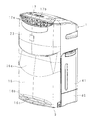
以下、本発明に係る送風装置の実施の形態を図面に基づいて説明する。図1は本発明に係る送風装置を搭載した空気清浄機の前側の外観斜視図、図2は図1に示す空気清浄機の正面図、図3は図1に示す空気清浄機の側面図、図4は図1に示す空気清浄機の側面断面図、図5は図1に示す空気清浄機の正面断面図である。 DESCRIPTION OF EMBODIMENTS Hereinafter, embodiments of a blower according to the present invention will be described with reference to the drawings. 1 is an external perspective view of the front side of an air cleaner equipped with a blower according to the present invention, FIG. 2 is a front view of the air cleaner shown in FIG. 1, and FIG. 3 is a side view of the air cleaner shown in FIG. 4 is a side sectional view of the air cleaner shown in FIG. 1, and FIG. 5 is a front sectional view of the air cleaner shown in FIG.
本発明に係る送風装置を搭載した空気清浄機は、矩形状の箱体を垂直に立てたような外形のハウジング1を備え、ハウジング1の内部は隔壁11によって前後に仕切られている(図4)。隔壁11は上側の略半分が後方に傾斜している。
An air purifier equipped with a blower according to the present invention includes a
隔壁11の後側に、浄化用の各種フィルタを収納するフィルタ収納部1aが形成されている。フィルタ収納部1aは、ハウジング1の後面側に開口し、直方体状に窪んだ空間であり、フィルタ収納部1aには、後側より順に、脱臭フィルタ7a及び集塵フィルタ7bが重ね合わされた状態で収納されている。
On the rear side of the
脱臭フィルタ7aは、空気中の臭い成分であるアセトアルデヒドやアンモニアや酢酸等を吸着する機能を有し、長方形をなす枠体にポリエステル製の不織布を取り付け、その上に活性炭を均一に分散配置し、その上からポリエステル製の不織布を被せた構造である。 The deodorizing filter 7a has a function of adsorbing acetaldehyde, ammonia, acetic acid, etc., which are odorous components in the air, and a non-woven fabric made of polyester is attached to a rectangular frame body, and activated carbon is uniformly distributed on the rectangular frame, It is the structure which covered the nonwoven fabric made from polyester on it.
集塵フィルタ7bは、微細な塵埃を捕集する機能を有し、いわゆるHEPA(High Efficiency Particulate Air)フィルタで構成してある。該HEPAフィルタは、ポリエステル/ビニロン系不織布からなる骨材に電石加工したメルトブロー不織布を合わせて濾材とし、これを折り畳み、その上下面にハイドロキシアパタイト加工した不織布からなる抗菌シートを重ねて熱圧着し、ホットメルト付き不織布からなる枠を溶着した構造である。 The dust collection filter 7b has a function of collecting fine dust, and is configured by a so-called HEPA (High Efficiency Particulate Air) filter. The HEPA filter is obtained by combining an aggregate made of polyester / vinylon non-woven fabric with a melt blown non-woven fabric processed with stone, and folding it, and then anti-bonding an antibacterial sheet made of non-woven fabric processed with hydroxyapatite on the upper and lower surfaces thereof, and thermocompression bonding, It is the structure which welded the frame which consists of a nonwoven fabric with a hot melt.
フィルタ収納部1aの開口を覆う着脱可能な後パネル2が備えられている。脱臭フィルタ7a及び集塵フィルタ7bは、後パネル2によってフィルタ収納部1aからの脱落が防止される。後パネル2は概ね矩形の板状をなし、マトリックス状に複数の小孔からなる吸込口2aが形成され、裏面にはメッシュ状の繊維シートが貼り付けてある。
A detachable
集塵フィルタ7bの前側に、加湿フィルタユニット3及び水槽4が配されている。水槽4はハウジング1の底板上に載置され、水槽4に支持される加湿フィルタユニット3と共に、ハウジング1の一側部から外部に引き出すことが可能である。
The
加湿フィルタユニット3は、吸水性及び通気性を有し、ジグザグに折り畳まれた円盤状の吸水フィルタ31及び吸水フィルタ31を収納保持する円環状の保持枠30からなる。吸水フィルタ31は適宜の厚さを有するフィルタ素材を打ち抜いて作製される。保持枠30は合成樹脂製である。
The humidifying
保持枠30の外周面には、幅方向の中央部に全周に亘って歯が形成されたリングギア32が設けてある。水槽4内の下部には、軸心が水槽4の幅方向に沿った2つの鼓形の支持ローラ6,6が水槽4の長手方向に振り分け配置されている。各支持ローラ6は、水槽4の幅方向の両側壁に回転自在に支持されている。
On the outer peripheral surface of the
各支持ローラ6はリングギア32の両側面に転接することにより、加湿フィルタユニット3の保持枠30を下部から支えると共に、水槽4の幅方向の位置決めをする。加湿フィルタユニット3は下部を水槽4の内部に差し込み、垂直に立ち上がる姿勢で支持されている。
Each
保持枠30のリングギア32は保持枠30の上方に配した駆動ユニット5の駆動歯車51に噛合されている。駆動ユニット5は駆動歯車51の他に、駆動歯車51と噛合する伝動歯車及び出力軸が伝動歯車に連結された駆動モータ(不図示)を備え、ハウジング1内の適宜位置に固定されている。
The
隔壁11の前面側に風路カバー12が取り付けられている。風路カバー12は、下側の円筒部12aと、円筒部12aの外周部に下端が連なる扁平状の上側の角筒部12b(但し、隔壁11側が開口している)とからなる。円筒部12aは、隔壁11の下側部分と略平行な円形の底壁部12a1と、底壁部12a1の縁部全周と隔壁11とを接続する側壁部12a2とを有している。角筒部12bは、隔壁11の上側部分と略平行に対向した状態で後方に傾斜した壁部12b1と、該壁部12b1の縁部全周と隔壁11とを接続する側壁部12b2とを有している。
An air path cover 12 is attached to the front surface side of the
加湿フィルタユニット3の前側に、隔壁11を隔てて送風機8が配置され、隔壁11の下部には送風機8に通じる複数の通気孔11aが形成されている。送風機8はファン81及び該ファン81を回転駆動するファンモータ82を備え、風路カバー12の底壁部12a1にファンモータ82が固定されている。ファン81はターボファンであるが、その他、プロペラファンやクロスフローファンを採用してもよい。ファンモータ82は駆動制御の容易性を重視して直流モータを用いている。
A
送風機8の上方側に位置し、隔壁11と風路カバー12の角筒部12bとで囲まれた空間が吹出風路13に形成されている。ハウジング1の上面は、後側部分が前側部分より低くなるように傾斜し、この傾斜した後側部分に、吹出風路13に連通した上向き開口の吹出口15が設けてある。吹出口15には風向板15aが設けてある。風向板15aは吹き出し空気の方向を斜め後方側から上方側の所定範囲で変更することが可能である。
A space that is located above the
送風機8のファンモータ82の駆動によりファン81が回転し、後パネル2の吸込口2aから外部の空気(室内の空気)が吸い込まれ、吸い込まれた空気は、脱臭フィルタ7a及び集塵フィルタ7bを通過する際の臭いや塵埃のない空気に浄化される。浄化された空気は、吸水フィルタ31で加湿され、又は加湿をされずに、隔壁11の通気孔11aからファン81の中心部に吸い込まれる。ファン81の中心部に吸い込まれた空気は、ファンブレード同士の間を通りファン81の外周から吐き出され、吹出風路13を流れて上方に導かれて吹出口15から室内に吹き出される。
The
後方に傾斜した風路カバー12の角筒部12bの前側には、ハウジング1の前面に開口した吸込口18から横断面視で略「くの字」状に湾曲して上向きに伸び、ハウジング1の前面上部に設けた吹出口17に至る通風路20が設けてある。通風路20は、後壁20aと、前壁20bと、後壁20a及び前壁20bの両側の縁部を結ぶ側壁20cとで囲まれた空間である。
On the front side of the
吹出口17は正面視で横長の略長円又は楕円形状をなしている。吹出口17は、横方向に間隔を置いて並置された複数の縦姿勢の風向板17a及び横向きの風向板17bを備えている。縦姿勢の風向板17aは横方向の両端部側に位置するほど板面が流出側に向かって横外方向に開いている。その結果、吹出口17から前方に吹き出す空気の流れを横方向に広げることができる。横向きの風向板17bは前方側に吹き出す空気の流れを略水平状態にするためのものである。
The
通風路20の吹出口17に近い箇所に、ファン21cを取り付けた回転軸21bが横向きに配置されたクロスフローファン21が設けてある。回転軸21bは通風路20の両側の側壁20cに回転自在に支持されている。クロスフローファン21の駆動用のクロスフローファンモータ21aは通風路20の外に設置され、クロスフローファンモータ21aの出力軸が回転軸21bと同軸に配置されている。
A
吸込口18は横方向が吹出口17と同幅で縦方向の幅が吹出口17より広く、正面視で下縁部の中央部が下側に凸状をなす矩形状の開口を有する。吸込口18は上部がクロスフローファン21の前側に位置し、下部がクロスフローファン21より下側に位置し、前側に傾斜している。また吸込口18は、後パネル2に設けた吸込口2aに対して上側にある。具体的には、吸込口18の上端部は最上部位置の吸込口2aよりも高い位置にあり、吸込口18の下端部は、最上部位置の吸込口2aより低いがハウジング1の高さの略半分よりも上側の位置にあり、最下部位置の吸込口2aよりは高い位置にある。
The
吸込口18には防塵フィルタ19が縦姿勢に装着され、防塵フィルタ19はクロスフローファン21と接触しないように上部が下部に対して前側に傾斜している。なお、防塵フィルタ19の吸込口18への装着構造については後述する。
A dust-
吸込口18及び防塵フィルタ19の前方側を覆うように、前パネル23がハウジング1に固定されて垂下されている。前パネル23は吸込口18の形状に合わせて正面視で下縁部の中央部が下側に凸状をなし、又、中央部が前側に突き出るように左右方向に湾曲している。
A
通風路20のクロスフローファン21と吹出口17との間の壁面に、正負のイオンを発生させるイオン発生器22が配設されている。イオン発生器22には、針状の放電電極(不図示)が風路内に露出するように設けられ、放電電極に給電部(不図示)から交流波形またはインパルス波形の電圧を供給することによって放電電極がイオンを発生する。
An
クロスフローファン21のクロスフローファンモータ21a及びイオン発生器22が駆動されると、クロスフローファン21によって吹出口17から吸い込まれた空気に、イオン発生器22により発生したイオンが付加され、イオンを含む空気が吹出口17より前方側に吹き出される。
When the crossflow fan motor 21a and the
放電電極の印加電圧が正電圧の場合はイオンが空気中の水分と結合して主としてH+ (H2 O)m から成るプラスイオンを発生する。放電電極の印加電圧が負電圧の場合はイオンが空気中の水分と結合して主としてO2 -(H2 O)n から成るマイナスイオンを発生する。ここで、m、nは任意の自然数である。H+ (H2 O)m 及びO2 -(H2 O)n は空気中の浮遊菌や臭い成分の表面で凝集してこれらを取り囲む。 When the voltage applied to the discharge electrode is a positive voltage, the ions are combined with moisture in the air to generate positive ions mainly composed of H + (H 2 O) m . When the voltage applied to the discharge electrode is a negative voltage, the ions are combined with moisture in the air to generate negative ions mainly composed of O 2 − (H 2 O) n . Here, m and n are arbitrary natural numbers. H + (H 2 O) m and O 2 − (H 2 O) n aggregate on the surface of airborne bacteria and odorous components and surround them.
そして、式(1)〜(3)に示すように、衝突により活性種である[・OH](水酸基ラジカル)やH2O2(過酸化水素)を微生物等の表面上で凝集生成して浮遊菌や臭い成分を破壊する。ここで、m’、n’は任意の自然数である。従って、プラスイオン及びマイナスイオンを発生して吹出口から吐出することにより使用者の近傍の殺菌及び臭い除去を行うことができる。
H+ (H2 O)m +O2 -(H2 O)n →・OH+1/2O2 +(m+n)H2 O ・・・(1)
H+ (H2 O)m +H+ (H2 O)m ’+O2 -(H2 O)n +O2 -(H2 O)n ’
→ 2・OH+O2 +(m+m'+n+n')H2 O・・・(2)
H+ (H2 O)m +H+ (H2 O)m ’+O2 -(H2 O)n +O2 -(H2 O)n ’
→H2O2+O2 +(m+m'+n+n')H2 O・・・(3)
Then, as shown in the formulas (1) to (3), the active species [.OH] (hydroxyl radical) and H 2 O 2 (hydrogen peroxide) are aggregated and formed on the surface of the microorganism or the like by collision. Destroy airborne bacteria and odorous components. Here, m ′ and n ′ are arbitrary natural numbers. Therefore, sterilization and odor removal in the vicinity of the user can be performed by generating positive ions and negative ions and discharging them from the outlet.
H + (H 2 O) m + O 2 - (H 2 O) n → · OH + 1 /
H + (H 2 O) m + H + (H 2 O) m '+ O 2 - (H 2 O) n + O 2 - (H 2 O) n'
→ 2 OH + O 2 + (m + m ′ + n + n ′) H 2 O (2)
H + (H 2 O) m + H + (H 2 O) m '+ O 2 - (H 2 O) n + O 2 - (H 2 O) n'
→ H 2 O 2 + O 2 + (m + m ′ + n + n ′) H 2 O (3)
尚、本実施形態ではイオン発生器22によってプラスイオン及びマイナスイオンを発生しているが、マイナスイオンのみを発生してもよい。
In this embodiment, positive ions and negative ions are generated by the
ハウジング1は、風路カバー12の前側を覆う前カバー16を前面下部に備えている。前カバー16は上部に上部側ほど後方に緩やかに傾斜した上傾斜面16aを有する。前カバー16は下端部に横方向に伸びる凹溝部16cを有し、凹溝部16cの底部は開口している。凹溝部16cの上側斜面が下部側ほど後方に急傾斜した下傾斜面16bを形成している。
The
ハウジング1の底面には、ロック機構付きの複数の車輪9が取り付けてある。これにより、車輪9のロック機構を解除して空気清浄機を室内の適所に移動させた後、ロック機構を作動させて空気清浄機を床上で移動しない状態で設置することができる。
A plurality of
次に以上の如き構成の空気清浄機による空気の流れについて説明する。空気清浄機は壁W際の床面Fに設置してある。上面の吹出口15から斜め後方上向きに吹き出された清浄空気は背側の壁W、天井及び向かい側の壁(不図示)を経て室内を循環した後、空気清浄機の前面側に戻り、前カバー16に当たる。前カバー16の上側部分に当たった空気は上傾斜面16aに沿って流れ、前パネル23と上傾斜面16aとの間隙を通ってイオン用の吸込口18に吸引される。吸込口18に吸引された空気は防塵フィルタ19にて埃が除去され、通風路20を流れるときにイオンを付加され、吹出口17から前方側に吹き出される。尚、吹出口17から前方側に吹き出された空気も循環して空気清浄機の前面側に戻る。
Next, the flow of air by the air cleaner having the above configuration will be described. The air purifier is installed on the floor F at the wall W. The clean air blown obliquely upward and upward from the
一方、前カバー16の下側部分に当たった空気は凹溝部16cに入って下傾斜面16bに沿って流れ、さらに底面と床面Fとの間を流れて背面側に達し、吸込口2aに吸引される。吸込口2aに吸引された空気は脱臭フィルタ7a、集塵フィルタ7b及び加湿フィルタユニット3を通過して浄化及び加湿され(又は加湿されず)、上面の吹出口15から吹き出される。以下、このような空気の循環を繰り返す。
On the other hand, the air hitting the lower part of the
次に、防塵フィルタ19の吸込口18への装着構造の実施の形態について説明する。
(実施の形態1)
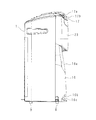
図6は本発明に係る送風装置の実施の形態1の主要部を模式的に示す側面断面図、図7は同送風装置の動作を模式的に説明する側面断面図である。
Next, an embodiment of a structure for mounting the
(Embodiment 1)
FIG. 6 is a side cross-sectional view schematically showing the main part of
防塵フィルタ19は、メッシュ部19aと周囲の枠部19bとで構成される。防塵フィルタ19は、枠部19bが吸込口18の縁部に当接した状態で図示しない案内枠で両側を案内され、下側から上方にスライドして装着される。装着方向の先端側の枠部19bが通風路20の前壁20bに設けたストッパー25に当たることによって装着位置が決められる。吸込口18に装着された状態では、装着方向におけるメッシュ部19aの端部が吸込口18の縁部より外側(上側)に位置している。
The
装着された防塵フィルタ19を吸込口18から取り外す場合は、枠部19bが吸込口18の縁部に当接した状態で下方にスライドさせて吸込口18から取り外される。この際に、衝撃によりメッシュ部19aに付着した一部の埃等Dが飛散するが、取り外し操作の初期では吸込口18の上側部分は、装着状態で吸込口18の縁部より外側(上側)に位置していたメッシュ部19aで覆われるので、吸込口18から内部側への空気の吸引により、飛散した埃等Dは埃等Dが付着していないメッシュ部19aに付着し、通風路20の内部へは吸い込まれない。
When the attached
(実施の形態2)
図8は本発明に係る送風装置の実施の形態2の主要部を模式的に示す側面断面図、図9は同送風装置の動作を模式的に説明する側面断面図である。
(Embodiment 2)
FIG. 8 is a side sectional view schematically showing the main part of the second embodiment of the blower according to the present invention, and FIG. 9 is a side sectional view schematically explaining the operation of the blower.
実施の形態2では、メッシュ部19aの端部を吸込口18の縁部より外側(上側)に位置させる代わりに、吸込口18に対する装着方向の端部に、吸込口18から離れる向きに突出した突出部19cを装着方向と交差する方向に延設するように枠部19bに設けてある点が実施の形態1と異なる。
In
装着された防塵フィルタ19を吸込口18から取り外す際に、衝撃によりメッシュ部19aに付着した一部の埃等Dが飛散するが、飛散した埃等Dは突出部19cによって強制的に下側に移動させられるので、吸込口18から通風路20の内部へは吸い込まれない。
When the attached
(実施の形態3)
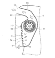
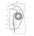
図10は本発明に係る送風装置の実施の形態3の主要部を模式的に示す側面断面図、図11は同送風装置の制御構成を示す回路ブロック図、図12は同送風装置の動作を模式的に説明する側面断面図である。
(Embodiment 3)
FIG. 10 is a side sectional view schematically showing the main part of the third embodiment of the blower according to the present invention, FIG. 11 is a circuit block diagram showing the control configuration of the blower, and FIG. 12 shows the operation of the blower. It is side surface sectional drawing typically demonstrated.
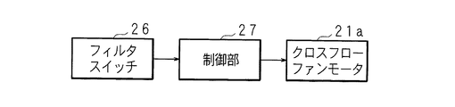
実施の形態3では、防塵フィルタ19の吸込口18への装着の有無を検出するフィルタスイッチ26を通風路20の前壁20bに設け、フィルタスイッチ26の検出情報は制御部27に入力されている。制御部27からはクロスフローファン21のクロスフローファンモータ21aに対する駆動信号が出力されている。フィルタスイッチ26は防塵フィルタ19の枠部19bに当接するマイクロスイッチ等で構成される。
In the third embodiment, a
装着された防塵フィルタ19を吸込口18から取り外す際に、衝撃によりメッシュ部19aに付着した一部の埃等Dが飛散するが、防塵フィルタ19を取り外したことがフィルタスイッチ26で検出されると、制御部27はクロスフローファン21のクロスフローファンモータ21aの作動を停止させるので、吸込口18から内部側への空気が吸引されなくなり、飛散した埃等Dは吸込口18から通風路20の内部へは吸い込まれない。
When the attached
本発明において、発生させるイオンは帯電微粒子水も含むものとする。この時、イオン発生器は静電霧化装置から成り、静電霧化装置によってラジカル成分を含む帯電微粒子水が生成される。即ち、静電霧化装置に設けた放電電極をペルチェ素子により冷却することで放電電極の表面に結露水が生じる。次に、放電電極にマイナスの高電圧を印加すると、結露水から帯電微粒子水が生成される。また、放電電極からは帯電微粒子水とともに空気中に放出されるマイナスイオンも発生する。 In the present invention, the generated ions include charged fine particle water. At this time, the ion generator includes an electrostatic atomizer, and charged fine particle water containing a radical component is generated by the electrostatic atomizer. That is, condensation water is generated on the surface of the discharge electrode by cooling the discharge electrode provided in the electrostatic atomizer by the Peltier element. Next, when a negative high voltage is applied to the discharge electrode, charged fine particle water is generated from the dew condensation water. In addition, negative ions released into the air together with the charged fine particle water are also generated from the discharge electrode.
上記の実施の形態1−3の送風装置では、通風路20に防塵フィルタ19のみを配したが、浄化能力を高めるために、脱臭フィルタ7a及び集塵フィルタ7bと同様の脱臭フィルタ及び集塵フィルタを配置してもよい。
In the blower of Embodiment 1-3 described above, only the
上記の実施の形態1−3では、前パネル23がハウジング1に固定されているが、例えば、前パネル23がハウジング1に対して上側に摺動可能又は上部側を支点とした前側に揺動可能に構成にすることにより、着脱操作時に防塵フィルタ19の状態を確認し易いようにすることも可能である。
In Embodiment 1-3 described above, the
本発明に係る送風装置は、上記の3つの実施の形態1−3のうちの何れか2つの実施の形態を備えた送風装置、又は、実施の形態1−3の全てを備えた送風装置でもよい。 The blower according to the present invention may be a blower provided with any two of the above-described three embodiments 1-3 or a blower provided with all of the embodiments 1-3. Good.
なお、今回開示した実施の形態は、全ての点で例示であって、制限的なものではないと考えられるべきである。本発明の範囲は、特許請求の範囲内での全ての変更及び特許請求の範囲と均等の範囲が含まれることが意図される。 The embodiment disclosed this time should be considered as illustrative in all points and not restrictive. The scope of the present invention is intended to include all modifications within the scope of the claims and the scope equivalent to the scope of the claims.
18 吸込口
19 防塵フィルタ(フィルタ)
19c 突出部
21 クロスフローファン(送風機)
26 フィルタスイッチ(検出手段)
27 制御部
18
26 Filter switch (detection means)
27 Control unit
Claims (3)
前記フィルタは、前記吸込口に装着された状態で前記吸込口に対する装着方向の端部が前記吸込口の縁部よりも外側に位置するよう構成してあることを特徴とする送風装置。 In a blower apparatus that includes a filter that is detachably mounted in a state in contact with the edge of the suction port, and blows out the air sucked through the filter from the suction port by the operation of the blower.
The blower device, wherein the filter is configured such that an end portion in a mounting direction with respect to the suction port is positioned outside an edge portion of the suction port in a state where the filter is mounted in the suction port.
前記フィルタは、前記吸込口に対する装着方向の端部に、前記吸込口から離れる向きに突出した突出部を前記装着方向と交差する方向に延設してあることを特徴とする送風装置。 In a blower apparatus that includes a filter that is detachably mounted in a state in contact with the edge of the suction port, and blows out the air sucked through the filter from the suction port by the operation of the blower.
The air blower characterized in that the filter has a protruding portion protruding in a direction crossing the mounting direction at an end in a mounting direction with respect to the suction port.
前記フィルタの前記吸込口への装着の有無を検出する検出手段と、該検出手段の検出結果に基づいて前記フィルタが前記吸込口に装着されていないことが検出されたときに前記送風機の作動を停止する制御部とを備えていることを特徴とする送風装置。 In a blower apparatus that includes a filter that is detachably mounted in a state in contact with the edge of the suction port, and blows out the air sucked through the filter from the suction port by the operation of the blower.
Detecting means for detecting whether or not the filter is attached to the suction port; and operating the blower when it is detected that the filter is not attached to the suction port based on a detection result of the detection means. A blower characterized by comprising a control unit that stops.
Priority Applications (1)
| Application Number | Priority Date | Filing Date | Title |
|---|---|---|---|
| JP2011219504A JP2013078718A (en) | 2011-10-03 | 2011-10-03 | Blowing apparatus |
Applications Claiming Priority (1)
| Application Number | Priority Date | Filing Date | Title |
|---|---|---|---|
| JP2011219504A JP2013078718A (en) | 2011-10-03 | 2011-10-03 | Blowing apparatus |
Related Child Applications (1)
| Application Number | Title | Priority Date | Filing Date |
|---|---|---|---|
| JP2016037301A Division JP2016137488A (en) | 2016-02-29 | 2016-02-29 | Air blowing device |
Publications (1)
| Publication Number | Publication Date |
|---|---|
| JP2013078718A true JP2013078718A (en) | 2013-05-02 |
Family
ID=48525557
Family Applications (1)
| Application Number | Title | Priority Date | Filing Date |
|---|---|---|---|
| JP2011219504A Pending JP2013078718A (en) | 2011-10-03 | 2011-10-03 | Blowing apparatus |
Country Status (1)
| Country | Link |
|---|---|
| JP (1) | JP2013078718A (en) |
Cited By (2)
| Publication number | Priority date | Publication date | Assignee | Title |
|---|---|---|---|---|
| JP2015150557A (en) * | 2014-02-18 | 2015-08-24 | ブルーエアー・エービー | Air cleaner provided with fan duct |
| JP2016153550A (en) * | 2015-02-20 | 2016-08-25 | Toto株式会社 | Deodorizing device for toilet |
Citations (11)
| Publication number | Priority date | Publication date | Assignee | Title |
|---|---|---|---|---|
| JPS6065538U (en) * | 1983-10-12 | 1985-05-09 | 松下精工株式会社 | ventilation fan |
| JPS6226077U (en) * | 1985-07-29 | 1987-02-17 | ||
| JPS6276826U (en) * | 1985-10-30 | 1987-05-16 | ||
| JPS63149214U (en) * | 1987-03-23 | 1988-09-30 | ||
| JPH044618U (en) * | 1990-04-20 | 1992-01-16 | ||
| JPH06272887A (en) * | 1993-03-19 | 1994-09-27 | Sharp Corp | Air-conditioner machine |
| US5496389A (en) * | 1993-04-08 | 1996-03-05 | Microzone Corporation | Clean air fan filter module |
| JPH09313853A (en) * | 1996-06-04 | 1997-12-09 | Tiger Vacuum Bottle Co Ltd | Air cleaner |
| JP2001208417A (en) * | 2000-01-31 | 2001-08-03 | Daikin Ind Ltd | Filter and fixing structure of filter |
| JP2003326123A (en) * | 2002-05-09 | 2003-11-18 | Matsushita Electric Ind Co Ltd | Air filter and blower device using the same |
| JP2006000788A (en) * | 2004-06-18 | 2006-01-05 | Matsushita Electric Works Ltd | Filter |
-
2011
- 2011-10-03 JP JP2011219504A patent/JP2013078718A/en active Pending
Patent Citations (11)
| Publication number | Priority date | Publication date | Assignee | Title |
|---|---|---|---|---|
| JPS6065538U (en) * | 1983-10-12 | 1985-05-09 | 松下精工株式会社 | ventilation fan |
| JPS6226077U (en) * | 1985-07-29 | 1987-02-17 | ||
| JPS6276826U (en) * | 1985-10-30 | 1987-05-16 | ||
| JPS63149214U (en) * | 1987-03-23 | 1988-09-30 | ||
| JPH044618U (en) * | 1990-04-20 | 1992-01-16 | ||
| JPH06272887A (en) * | 1993-03-19 | 1994-09-27 | Sharp Corp | Air-conditioner machine |
| US5496389A (en) * | 1993-04-08 | 1996-03-05 | Microzone Corporation | Clean air fan filter module |
| JPH09313853A (en) * | 1996-06-04 | 1997-12-09 | Tiger Vacuum Bottle Co Ltd | Air cleaner |
| JP2001208417A (en) * | 2000-01-31 | 2001-08-03 | Daikin Ind Ltd | Filter and fixing structure of filter |
| JP2003326123A (en) * | 2002-05-09 | 2003-11-18 | Matsushita Electric Ind Co Ltd | Air filter and blower device using the same |
| JP2006000788A (en) * | 2004-06-18 | 2006-01-05 | Matsushita Electric Works Ltd | Filter |
Cited By (2)
| Publication number | Priority date | Publication date | Assignee | Title |
|---|---|---|---|---|
| JP2015150557A (en) * | 2014-02-18 | 2015-08-24 | ブルーエアー・エービー | Air cleaner provided with fan duct |
| JP2016153550A (en) * | 2015-02-20 | 2016-08-25 | Toto株式会社 | Deodorizing device for toilet |
Similar Documents
| Publication | Publication Date | Title |
|---|---|---|
| JP5836549B2 (en) | Air purifier and method of using air purifier | |
| JP6076858B2 (en) | Air cleaner | |
| JP2005219049A (en) | Separate-type air conditioner | |
| JP2016137488A (en) | Air blowing device | |
| JP5808996B2 (en) | Air purifier and method of using air purifier | |
| CN203036792U (en) | Humidification device | |
| JP5980637B2 (en) | Air conditioner | |
| JP2017155976A (en) | Humidification filter and humidifier | |
| JP6353561B2 (en) | Air cleaner | |
| JP6225225B2 (en) | Air conditioner | |
| JP2008032387A (en) | Air conditioner | |
| JP2007296524A (en) | Air conditioner | |
| JP2017217981A (en) | Air cleaner | |
| JP2013078718A (en) | Blowing apparatus | |
| JP2013220399A (en) | Air conditioner | |
| JP2008008564A (en) | Air conditioner | |
| JP2013078719A (en) | Air purifier | |
| JP2012026692A (en) | Air cleaner | |
| JP2015129595A (en) | air conditioner | |
| JP2007113859A (en) | Air conditioner | |
| JP4165246B2 (en) | Air conditioner | |
| WO2013047132A2 (en) | Air purifier | |
| JP2012117770A (en) | Humidifying air cleaner | |
| JP6137799B2 (en) | Blower | |
| JP2005049048A (en) | Air conditioner |
Legal Events
| Date | Code | Title | Description |
|---|---|---|---|
| A621 | Written request for application examination |
Free format text: JAPANESE INTERMEDIATE CODE: A621 Effective date: 20140918 |
|
| A977 | Report on retrieval |
Free format text: JAPANESE INTERMEDIATE CODE: A971007 Effective date: 20150617 |
|
| A131 | Notification of reasons for refusal |
Free format text: JAPANESE INTERMEDIATE CODE: A131 Effective date: 20150623 |
|
| A521 | Request for written amendment filed |
Free format text: JAPANESE INTERMEDIATE CODE: A523 Effective date: 20150730 |
|
| A131 | Notification of reasons for refusal |
Free format text: JAPANESE INTERMEDIATE CODE: A131 Effective date: 20150818 |
|
| A521 | Request for written amendment filed |
Free format text: JAPANESE INTERMEDIATE CODE: A523 Effective date: 20150831 |
|
| A02 | Decision of refusal |
Free format text: JAPANESE INTERMEDIATE CODE: A02 Effective date: 20160119 |