JP2008008564A - Air conditioner - Google Patents
Air conditioner Download PDFInfo
- Publication number
- JP2008008564A JP2008008564A JP2006180617A JP2006180617A JP2008008564A JP 2008008564 A JP2008008564 A JP 2008008564A JP 2006180617 A JP2006180617 A JP 2006180617A JP 2006180617 A JP2006180617 A JP 2006180617A JP 2008008564 A JP2008008564 A JP 2008008564A
- Authority
- JP
- Japan
- Prior art keywords
- air
- filter
- port
- outlet
- charging unit
- Prior art date
- Legal status (The legal status is an assumption and is not a legal conclusion. Google has not performed a legal analysis and makes no representation as to the accuracy of the status listed.)
- Pending
Links
Images
Landscapes
- Air Filters, Heat-Exchange Apparatuses, And Housings Of Air-Conditioning Units (AREA)
Abstract
【課題】 電気式空気清浄機からなる帯電部の放電極に埃が絡みにくいようにし、また、対向電極は汚れの臭い成分を分解できるようにして、綺麗な空気を被空調室内に供給できるようにするとともに、メンテナンスを実施するまでの期間を長くすることができるようにした空気調和機を提供する。
【解決手段】 吸込口1と吹出口2とを結ぶ空気通路にフィルタ3と、熱交換器4と、送風ファン5とを設けてなる空気調和機において、前記フィルタ3の風上側に電気式空気清浄機9からなる帯電部を設け、吹出空気の一部を前記帯電部に流通させるようにしたことを特徴としている。
【選択図】 図1PROBLEM TO BE SOLVED: To supply clean air to an air-conditioned room by preventing dust from being entangled with a discharge electrode of a charging unit composed of an electric air cleaner, and allowing a counter electrode to decompose dirt odor components. And an air conditioner capable of extending the period until maintenance is performed.
In an air conditioner in which a filter 3, a heat exchanger 4, and a blower fan 5 are provided in an air passage that connects a suction port 1 and a blower port 2, electric air is provided on the windward side of the filter 3. A charging unit comprising a cleaner 9 is provided, and a part of the blown air is circulated to the charging unit.
[Selection] Figure 1
Description
本発明は、空気調和機に係わり、より詳細には、電気式空気清浄機からなる帯電部の放電極に埃が絡みにくいようにし、また、対向電極は汚れの臭い成分を分解できるようにして、綺麗な空気を被空調室内に供給できるようにするとともに、メンテナンスを実施するまでの期間を長くすることができるようにした構造に関する。 The present invention relates to an air conditioner, and more particularly, to prevent dust from being entangled with a discharge electrode of a charging unit composed of an electric air cleaner, and to allow a counter electrode to decompose a odor component of dirt. The present invention relates to a structure capable of supplying clean air into an air-conditioned room and extending a period until maintenance is performed.
従来の空気調和機において、コロナ放電をさせずに空気イオンのみを放出するマイナス帯電部を用いて塵埃を帯電させるマイナスイオン発生装置の放電電極構成を最適化することにより、塵埃帯電効率を最大化し、安定した放電特性を有し、さらに通風特性を向上させた電気集塵装置を得ることを目的として、
マイナスイオン発生装置のマイナス電位に荷電する放電電極針をアース電極である対向電極に対して下流側に配置、あるいはマイナス電位に荷電する放電電極の針先を上流方向に向ける、あるいはアース電極は風の流れに平行に配置される、あるいは電極部を保護する格子間隔を風の上流側よりも下流側を粗くすることによって、塵埃集塵能力を向上させかつ針先や対向電極部への塵埃の堆積を抑制することによって異音等のない安定した集塵装置としてなるものが開示されていた(例えば、特許文献1参照。)。
In conventional air conditioners, dust charging efficiency is maximized by optimizing the discharge electrode configuration of the negative ion generator that charges dust using a negative charging unit that discharges only air ions without corona discharge. In order to obtain an electrostatic precipitator that has stable discharge characteristics and improved ventilation characteristics,
The discharge electrode needle charged to the negative potential of the negative ion generator is arranged downstream of the counter electrode as the ground electrode, or the needle tip of the discharge electrode charged to the negative potential is directed upstream, or the ground electrode is wind By arranging the lattice spacing that is parallel to the flow of the air or that protects the electrode part to be rougher on the downstream side than on the upstream side of the wind, the dust collection ability is improved and the dust collected on the tip and counter electrode part is improved. What has been disclosed as a stable dust collector free from abnormal noise by suppressing accumulation has been disclosed (for example, see Patent Document 1).
しかしながら、上述した集塵装置は、後述する特許文献1の図1に示すように、空気調和機の吸込口と吹出口とを結ぶ空気通路のフィルタ上流側に設けられた構成になっていることから、空気中の埃がフィルタに付着する前に、この埃が空気通路に露出した放電電極に付着してしまうという問題点を有していた。 However, the dust collector described above is configured to be provided on the upstream side of the filter of the air passage connecting the air inlet and the air outlet, as shown in FIG. Therefore, before the dust in the air adheres to the filter, the dust adheres to the discharge electrode exposed in the air passage.
前記放電電極に埃が付着した場合、放電電極から異常放電が発生して集塵機能が低下してしまうことから、機能を回復するためにこまめにメンテナンスを実施する必要性が生じることになって、ユーザにとって面倒な作業が伴ってしまうという問題点を有していた。
そこで、本発明は上述した課題を解決するためになされたものであって、その目的は、電気式空気清浄機からなる帯電部の放電極に埃が絡みにくいようにし、また、対向電極は汚れの臭い成分を分解できるようにして、綺麗な空気を被空調室内に供給できるようにするとともに、メンテナンスを実施するまでの期間を長くすることができるようにした空気調和機を提供することにある。 Accordingly, the present invention has been made to solve the above-described problems, and the object thereof is to make it difficult for dust to get entangled with the discharge electrode of the charging unit composed of an electric air cleaner, and for the counter electrode to become dirty. It is to provide an air conditioner that can decompose the odor components of the air and supply clean air to the air-conditioned room and can extend the period until maintenance is performed. .
上述した目的を達成するため、本発明は以下に示す特徴を備えている。 In order to achieve the above-described object, the present invention has the following features.
吸込口と吹出口とを結ぶ空気通路にフィルタと、熱交換器と、送風ファンとを設けてなる空気調和機において、
前記フィルタの風上側に、空気中に含まれた汚れの粒子を帯電させる帯電部を設け、吹出空気の一部を前記帯電部に流通させるようにしたことを特徴としている。
In an air conditioner comprising a filter, a heat exchanger, and a blower fan in an air passage connecting the suction port and the air outlet,
A charging unit for charging dirt particles contained in the air is provided on the windward side of the filter, and a part of the blown air is circulated to the charging unit.
本発明によれば、電気式空気清浄機からなり、埃を帯電させる帯電部の放電極に埃が絡みにくいようになり、また、対向電極は光触媒処理が施されることで、触媒を放電電圧により励起して分解能力を回生できる分解作用により汚れの臭い成分を分解できるようにして、綺麗な空気を被空調室内に供給できるようにするとともに、メンテナンスを実施するまでの期間を長くすることができるようにした空気調和機となる。 According to the present invention, dust is less likely to be entangled with the discharge electrode of the charging unit that charges the dust, and the counter electrode is subjected to photocatalytic treatment, so that the catalyst is discharged with a discharge voltage. It is possible to decompose the odor component of dirt by the decomposition action that can be excited and regenerate the decomposition ability, to supply clean air into the air-conditioned room, and to lengthen the period until maintenance is performed An air conditioner that can be used.
以下、本発明の実施の形態を、添付図面に基づいて詳細に説明する。 Embodiments of the present invention will be described below in detail with reference to the accompanying drawings.
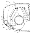
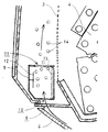
図1は本発明による空気調和機の断面図であり、図2は本発明による空気調和機の要部拡大断面図である。 FIG. 1 is a sectional view of an air conditioner according to the present invention, and FIG. 2 is an enlarged sectional view of a main part of the air conditioner according to the present invention.
本発明による空気調和機は、図1に示すように、室内の空気を吸い込む吸込口1と、後述する熱交換器で熱交換された空気を被空調室に吹き出す吹出口2とを結ぶ空気通路に、フィルタ3と熱交換器4と送風ファン5とを設け、前記吹出口2に、支軸部6aにより回動自在に軸支された風向偏向板6と、支軸部7aにより回動自在に軸支されたディフューザ7とを設けている。
As shown in FIG. 1, the air conditioner according to the present invention has an air passage that connects a suction port 1 that sucks in indoor air and a
前記吸込口1から吸い込まれた吸込空気は、その中に含まれた埃が前記フィルタ3によって取り除かれ、前記熱交換器4によって熱交換されたのち、前記送風ファン5によって前記吹出口2に送出されるとともに、前記風向偏向板6および前記ディフューザ7が図示しない駆動モータに駆動されて回動することにより、前記吹出口2が開放され、且つ風向が偏向されて被空調室に吹き出されるようになっている。
The suction air sucked from the suction port 1 is removed from the dust contained in the
その際、前記吹出口2の上壁面には、同吹出口2に前記送風ファン5によって送出された吹出空気の一部を、前記フィルタ3の風上側に導入するための導入口8が形成されている。
At that time, an
前記導入口8と前記フィルタ3との間には、前記導入口8に臨ませるような流通口10を備えた電気式空気清浄機9からなる帯電部が設けられており、空気中に含まれた汚れの粒子を帯電させることによって、帯電した汚れの粒子は前記フィルタ3と電位差をもつことになって同フィルタ3の表面に付着しやすくなる。
Between the
前記電気式空気清浄機9は、前記送風ファン5の風下側となるようにドレンパンに設けられており、前記吸込口1から吸い込まれた空気は前記フィルタ3および前記熱交換器4を流通させた後、図1に示す矢印のように、前記送風ファン5によって前記吹出口2に送出された吹出空気の一部を導入させる前記導入口8に臨ませるように前記流通口10が設けられていることから、導入された吹出空気の一部を円滑に取り入れることができるようになっている。
The
前記導入口8に導入される吹出空気は、図1に示すように、前記風向偏向板6および前記ディフューザ7で前記吹出口2を閉じることによって導入されるようになり、且つ前記流通口10を流通するようになっている。
As shown in FIG. 1, the blown air introduced into the
また、前記風向偏向板6および前記ディフューザ7を回動して前記吹出口2を開放した場合であっても、前記送風ファン5によって前記吹出口2に送出された吹出空気の一部は、前記導入口8に導入されて前記流通口10を流通することになる。
Even when the
そして、前記電気式空気清浄機9は、前記送風ファン5によって前記吹出口2に送出された吹出空気の一部を流通させていることから、前記フィルタ3を通過させたことで、前記電気式空気清浄機9の内部に吸込空気の中に含まれた埃が流入しなくなって、前記電気式空気清浄機9内部の放電極に埃が絡まりやすくなるといったおそれがなくなり、また、前記電気式空気清浄機9内部の対向電極がすぐに汚れてしまうといったおそれがなくなる。
And since the said electric
ここで、図2に基づいて、前記電気式空気清浄機9の構成について詳細に説明する。
Here, the configuration of the
前記電気式空気清浄機9は、図2に示す矢印のように、前記送風ファン5で前記吹出口2に送出された吹出空気の一部を前記導入口8から取り入れるための流通口10を下部に設ける一方、同流通口10よりも大きく形成された流出口11を上部に設けており、これら流通口10および流出口11の間に、一側に放電極12を備え、他側に同放電極12に対向する対向電極13を備えてなる放電部が設けられた構成になっている。
The
前記電気式空気清浄機9の放電部は、前記流通口10が前記導入口8に臨ませるように設けられたことで、前記フィルタ3および前記熱交換器4を通過して前記吹出口2に送出された吹出空気の一部が前記流通口10から円滑に取り入れられたのち、前記フィルタ3の風上側に向けて、前記流出口11から帯電用のマイナス(またはプラス)イオン14を効率よく供給できるようになっている。
The discharge part of the
前記吸込口1から吸込空気として吸い込まれた後、前記フィルタ3および前記熱交換器4を通過して前記吹出口2に送出された吹出空気は、前記フィルタ3によって大き目の埃が除去された状態であることから、その一部が前記導入口8から前記流通口10を経て前記電気式空気清浄機9の放電部を流通する際、上述したとおり、前記放電極12に埃が絡まるということを防止できるようになる。
After the air is sucked in from the suction port 1 as the suction air, the blown air sent to the
また、前記フィルタ3の風上側にマイナスイオン14を供給することで、前記吸込口1から吸い込まれた吸込空気中の微細な埃の粒子に帯電させて、前記フィルタ3によって吸着し除去できる効果を奏することになる。
Further, by supplying
前記放電部の対向電極13は、同対向電極13に例えば酸化チタンなどを蒸着または塗布することによって光触媒処理が施されており、これによって、放電極通電時は前記対向電極13に付着した汚れの臭い成分が常時自動的に分解除去できるようになっていることから、前記フィルタ3で取り除けなかった汚れの臭い成分が分解され、且つ、前記対向電極13のメンテナンスを実施するまでの期間を大幅に長くできることになる。
The
また、埃の荷電に使用されなかったマイナスイオン14は、最終的にはアースになっている前記熱交換器4に回収されるため、空気調和機本体から外部に出てしまうということがなく、したがって、被空調室内の調度品が帯電した埃によって汚れてしまうということもない。
Moreover, since the
前記電気式空気清浄機9の流通口10に対し、上述したように前記流出口11が大きく形成された構成になっており、これによって、前記電気式空気清浄機9が、前記流通口10から取り入れた空気を前記放電極12に直に当てることなく前記流出口11に向けて流通させることができることから、前記放電極12に埃が絡まるといったおそれを更に効果的になくすことができるようになる。
As described above, the
同時に、前記流出口11が前記流通口10よりも大きく形成されることで、前記吹出口2に送出された吹出空気の一部をショートサーキットさせることで前記電気式空気清浄機9の流通口10から取り入れて、コロナ放電により発生したマイナスイオン14を、前記フィルタ3の風上側に向けて多量に放出できるようになっている。
At the same time, since the
前記フィルタ3の風上側に放出されたマイナスイオン14は、上述したように、前記吸込口1から吸い込まれた吸込空気に含まれた汚れの粒子に付着して粒子を帯電させることになる。この帯電した粒子は前記フィルタ3と電位差をもつことになって、上述したとおり、同フィルタ3の表面に吸着しやすくなる。
As described above, the
以上説明したように、前記吸込口1から吸い込まれた吸込空気は、この吸込空気中に含まれた埃が前記フィルタ3によって効果的に除去されるとともに、前記熱交換器4によって熱交換された後、前記送風ファン5によって前記吹出口2に送出される。
As explained above, the suction air sucked from the suction port 1 is effectively removed by the
そして、前記吹出口2に送出された吹出空気の一部が前記導入口8を経て前記流通口10から前記電気式空気清浄機9内に取り込まれ、同電気式空気清浄機9で発生したマイナスイオン14を前記流出口11から前記フィルタ3の風上側に放出させる。
Then, a part of the blown air sent to the
前記フィルタ3の風上側に放出されたマイナスイオン14は、前記吸込口1から吸い込まれてきた空気中の汚れの粒子に付着して粒子を帯電させ、この帯電した粒子は前記フィルタ3に付着しやすくなる。
The
これにより、前記フィルタ3によって汚れの粒子がほとんど除去された空気をショートサーキットさせ、取り逃がした汚れの粒子は前記放電極12に対向する対向電極13に付着させて除去されることになり、また、同対向電極13の表面は光触媒処理されていることから、同対向電極13に付着した汚れの粒子は放電により活性化した光触媒によって分解除去されることになる。
As a result, the air from which the dirt particles have been almost removed by the
前記吹出口2に送出され前記導入口8に導入して、前記放電極12およびこれに対向する前記対向電極13からなる放電部を通過する空気は、前記フィルタ3によって汚れの粒子が除去されているため、前記放電極12に付着する汚れの粒子の量を従来より軽減できるようになり、前記対向電極13についても汚れの粒子を光触媒により分解できるようになって、メンテナンスを実施するまでの期間を長くすることができるようになる。
The air sent to the
また、前記吹出口2に送出される吹出空気の一部は繰り返し濾過されるため、従来よりも汚れの粒子の量が少ない空気をつくることが可能となり、更に、マイナスイオン14を空気調和機の外部に放出してしまうということがないので、被空調室の調度品等への汚れの粒子の付着がなくなるという効果を奏することになる。
In addition, since a part of the blown air sent to the
1 吸込口
2 吹出口
3 フィルタ
4 熱交換器
5 送風ファン
6 風向偏向板
6a 支軸部
7 ディフューザ
7a 支軸部
8 導入口
9 電気式空気清浄機
10 流通口
11 流出口
12 放電極
13 対向電極
14 マイナス(またはプラス)イオン
DESCRIPTION OF SYMBOLS 1
Claims (1)
前記フィルタの風上側に、空気中に含まれた汚れの粒子を帯電させる帯電部を設け、吹出空気の一部を前記帯電部に流通させるようにしたことを特徴とする空気調和機。 In an air conditioner comprising a filter, a heat exchanger, and a blower fan in an air passage connecting the suction port and the air outlet,
An air conditioner characterized in that a charging unit for charging dirt particles contained in the air is provided on the windward side of the filter, and a part of the blown air is circulated to the charging unit.
Priority Applications (1)
| Application Number | Priority Date | Filing Date | Title |
|---|---|---|---|
| JP2006180617A JP2008008564A (en) | 2006-06-30 | 2006-06-30 | Air conditioner |
Applications Claiming Priority (1)
| Application Number | Priority Date | Filing Date | Title |
|---|---|---|---|
| JP2006180617A JP2008008564A (en) | 2006-06-30 | 2006-06-30 | Air conditioner |
Publications (1)
| Publication Number | Publication Date |
|---|---|
| JP2008008564A true JP2008008564A (en) | 2008-01-17 |
Family
ID=39066936
Family Applications (1)
| Application Number | Title | Priority Date | Filing Date |
|---|---|---|---|
| JP2006180617A Pending JP2008008564A (en) | 2006-06-30 | 2006-06-30 | Air conditioner |
Country Status (1)
| Country | Link |
|---|---|
| JP (1) | JP2008008564A (en) |
Cited By (6)
| Publication number | Priority date | Publication date | Assignee | Title |
|---|---|---|---|---|
| JP2011163644A (en) * | 2010-02-09 | 2011-08-25 | Fujitsu General Ltd | Air conditioner |
| JP2012052777A (en) * | 2010-09-03 | 2012-03-15 | Daikin Industries Ltd | Indoor unit of air conditioner |
| JP2012052776A (en) * | 2010-09-03 | 2012-03-15 | Daikin Industries Ltd | Indoor unit of air conditioner |
| JP2012052779A (en) * | 2010-09-03 | 2012-03-15 | Daikin Industries Ltd | Active species generator and indoor unit of air conditioner |
| WO2013157746A1 (en) * | 2012-04-20 | 2013-10-24 | Lee Jung-Yeop | Cube-shaped base unit for prefabricated structure having rain gutter panel |
| WO2020189682A1 (en) * | 2019-03-20 | 2020-09-24 | シャープ株式会社 | Air conditioner |
Citations (4)
| Publication number | Priority date | Publication date | Assignee | Title |
|---|---|---|---|---|
| JP2002286278A (en) * | 2001-03-23 | 2002-10-03 | Toshiba Kyaria Kk | Air conditioner |
| JP2003247740A (en) * | 2002-02-26 | 2003-09-05 | Fujitsu General Ltd | Control method of air conditioner |
| JP2006071235A (en) * | 2004-09-06 | 2006-03-16 | Matsushita Electric Ind Co Ltd | Air conditioner with air purifier |
| JP2006125802A (en) * | 2004-11-01 | 2006-05-18 | Matsushita Electric Ind Co Ltd | Air conditioner |
-
2006
- 2006-06-30 JP JP2006180617A patent/JP2008008564A/en active Pending
Patent Citations (4)
| Publication number | Priority date | Publication date | Assignee | Title |
|---|---|---|---|---|
| JP2002286278A (en) * | 2001-03-23 | 2002-10-03 | Toshiba Kyaria Kk | Air conditioner |
| JP2003247740A (en) * | 2002-02-26 | 2003-09-05 | Fujitsu General Ltd | Control method of air conditioner |
| JP2006071235A (en) * | 2004-09-06 | 2006-03-16 | Matsushita Electric Ind Co Ltd | Air conditioner with air purifier |
| JP2006125802A (en) * | 2004-11-01 | 2006-05-18 | Matsushita Electric Ind Co Ltd | Air conditioner |
Cited By (6)
| Publication number | Priority date | Publication date | Assignee | Title |
|---|---|---|---|---|
| JP2011163644A (en) * | 2010-02-09 | 2011-08-25 | Fujitsu General Ltd | Air conditioner |
| JP2012052777A (en) * | 2010-09-03 | 2012-03-15 | Daikin Industries Ltd | Indoor unit of air conditioner |
| JP2012052776A (en) * | 2010-09-03 | 2012-03-15 | Daikin Industries Ltd | Indoor unit of air conditioner |
| JP2012052779A (en) * | 2010-09-03 | 2012-03-15 | Daikin Industries Ltd | Active species generator and indoor unit of air conditioner |
| WO2013157746A1 (en) * | 2012-04-20 | 2013-10-24 | Lee Jung-Yeop | Cube-shaped base unit for prefabricated structure having rain gutter panel |
| WO2020189682A1 (en) * | 2019-03-20 | 2020-09-24 | シャープ株式会社 | Air conditioner |
Similar Documents
| Publication | Publication Date | Title |
|---|---|---|
| JP2764711B2 (en) | Air cleaner | |
| CN101611269B (en) | Indoor machine for air conditioner | |
| KR20130063688A (en) | Set-type high-efficiency electrostatic precipitation system for air-purifying underground facilities | |
| CN1143092C (en) | Indoor unit of air conditioner | |
| CN121323085A (en) | Air purifier | |
| JP2008008564A (en) | Air conditioner | |
| JP2007021411A (en) | Electric dust collector and air conditioner | |
| JP3970707B2 (en) | Air cleaner | |
| JP2004286418A (en) | Air purification equipment | |
| JP2016137488A (en) | Blower | |
| JP2010063947A (en) | Air cleaner | |
| JP2010142773A (en) | Dust collector | |
| JP2009041817A (en) | Air conditioner | |
| KR200444737Y1 (en) | Air conditioner | |
| JP3211866B2 (en) | Air conditioner | |
| EP1652587A2 (en) | Air conditioner with electrostatic dust collector | |
| JP4323018B2 (en) | Air conditioner indoor unit | |
| JP2007107808A (en) | Air conditioner | |
| JP4167355B2 (en) | Air conditioner indoor unit | |
| CN114992718A (en) | Indoor unit and air conditioning system | |
| JP2005049048A (en) | Air conditioner | |
| CN214199073U (en) | Static-removing air curtain machine | |
| JP2013078718A (en) | Blowing apparatus | |
| CN207262587U (en) | high-efficiency air purifier | |
| JP2008045798A (en) | Air conditioner indoor unit |
Legal Events
| Date | Code | Title | Description |
|---|---|---|---|
| A621 | Written request for application examination |
Free format text: JAPANESE INTERMEDIATE CODE: A621 Effective date: 20080731 |
|
| A977 | Report on retrieval |
Free format text: JAPANESE INTERMEDIATE CODE: A971007 Effective date: 20100916 |
|
| A131 | Notification of reasons for refusal |
Free format text: JAPANESE INTERMEDIATE CODE: A131 Effective date: 20100928 |
|
| A02 | Decision of refusal |
Free format text: JAPANESE INTERMEDIATE CODE: A02 Effective date: 20110308 |