JP2013061338A - Three-mass coupled oscillation technique for mechanically robust micromachined gyroscope - Google Patents
Three-mass coupled oscillation technique for mechanically robust micromachined gyroscope Download PDFInfo
- Publication number
- JP2013061338A JP2013061338A JP2012200751A JP2012200751A JP2013061338A JP 2013061338 A JP2013061338 A JP 2013061338A JP 2012200751 A JP2012200751 A JP 2012200751A JP 2012200751 A JP2012200751 A JP 2012200751A JP 2013061338 A JP2013061338 A JP 2013061338A
- Authority
- JP
- Japan
- Prior art keywords
- mass
- mass body
- substrate
- gyroscope
- micromachining
- Prior art date
- Legal status (The legal status is an assumption and is not a legal conclusion. Google has not performed a legal analysis and makes no representation as to the accuracy of the status listed.)
- Pending
Links
Images


Classifications
-
- G—PHYSICS
- G01—MEASURING; TESTING
- G01C—MEASURING DISTANCES, LEVELS OR BEARINGS; SURVEYING; NAVIGATION; GYROSCOPIC INSTRUMENTS; PHOTOGRAMMETRY OR VIDEOGRAMMETRY
- G01C19/00—Gyroscopes; Turn-sensitive devices using vibrating masses; Turn-sensitive devices without moving masses; Measuring angular rate using gyroscopic effects
- G01C19/56—Turn-sensitive devices using vibrating masses, e.g. vibratory angular rate sensors based on Coriolis forces
- G01C19/5719—Turn-sensitive devices using vibrating masses, e.g. vibratory angular rate sensors based on Coriolis forces using planar vibrating masses driven in a translation vibration along an axis
- G01C19/5733—Structural details or topology
-
- Y—GENERAL TAGGING OF NEW TECHNOLOGICAL DEVELOPMENTS; GENERAL TAGGING OF CROSS-SECTIONAL TECHNOLOGIES SPANNING OVER SEVERAL SECTIONS OF THE IPC; TECHNICAL SUBJECTS COVERED BY FORMER USPC CROSS-REFERENCE ART COLLECTIONS [XRACs] AND DIGESTS
- Y10—TECHNICAL SUBJECTS COVERED BY FORMER USPC
- Y10T—TECHNICAL SUBJECTS COVERED BY FORMER US CLASSIFICATION
- Y10T29/00—Metal working
- Y10T29/49—Method of mechanical manufacture
Abstract
Description
マイクロマシニングによるジャイロスコープは、通常、コリオリ効果と呼ばれる物理現象に従って動作する角速度センサである。コリオリ効果は、単に、回転座標系から見た運動物体の偏差である。基板に実装された物体の場合、基板が回転するときに垂直平面内で振動(例えば、揺れ、運動又は駆動)しやすい。したがって、コリオリ効果を利用すべく、マイクロマシニングによるジャイロスコープは、少なくとも1つの質量体を備えた振動部と、振動部に対して垂直な平面内で自由に運動する検出部とで構成することができる。振動部が撓むことになるので、検出部はジャイロスコープの回転によって影響を受ける。外的な回転の下、振動質量体は撓み、その偏差は検出部の運動を通じて検出される。 A micromachining gyroscope is an angular velocity sensor that normally operates according to a physical phenomenon called the Coriolis effect. The Coriolis effect is simply the deviation of the moving object as seen from the rotating coordinate system. In the case of an object mounted on a substrate, it tends to vibrate (eg, shake, move or drive) in a vertical plane as the substrate rotates. Therefore, in order to use the Coriolis effect, the micromachining gyroscope can be configured by a vibrating unit including at least one mass body and a detecting unit that freely moves in a plane perpendicular to the vibrating unit. it can. Since the vibration part is bent, the detection part is affected by the rotation of the gyroscope. Under external rotation, the vibrating mass is deflected and the deviation is detected through the movement of the detector.
かかる振動型ジャイロスコープの感度は、その振幅に依存する。安定して高感度を達成するためには、安定した大きい振幅が好ましい。 The sensitivity of such a vibratory gyroscope depends on its amplitude. In order to stably achieve high sensitivity, a stable large amplitude is preferable.
一般に、大きい振動は、その共振周波数で動作する1自由度(1−DOF)振動子を使用して達成される。安定性は、安定化回路(例えば、位相ロックループ(PLL)、比例積分(PI)コントローラ)の助けを得て、この共振周波数付近でジャイロスコープを動作させ続けることにより得られる。 In general, large vibrations are achieved using a single degree of freedom (1-DOF) transducer operating at its resonant frequency. Stability is obtained by continuing to operate the gyroscope near this resonant frequency with the aid of a stabilizing circuit (eg, phase locked loop (PLL), proportional integral (PI) controller).
いくつかのケースでは、1自由度振動子を非共振周波数で動作させることができ、これにより安定化回路の必要性を低下させることができる。しかしながら、非共振周波数での振幅は、共振周波数での振幅より小さくなる。やはり、振動子が非共振周波数で振動する場合に、周波数及び品質係数の変化が振動の大きさに与える影響は、共振周波数で振動する場合に比べてより小さくなる。 In some cases, a one degree of freedom oscillator can be operated at a non-resonant frequency, which can reduce the need for a stabilization circuit. However, the amplitude at the non-resonant frequency is smaller than the amplitude at the resonant frequency. Again, when the vibrator vibrates at a non-resonant frequency, the influence of changes in frequency and quality factor on the magnitude of vibration is smaller than when the vibrator vibrates at the resonant frequency.
一般にジャイロスコープは、商業的用途の加速度計の10倍から20倍の電力を消費する。この電力消費の一部は、大きい振幅を得るために使用される櫛歯駆動に起因する。櫛歯駆動は、2つの櫛歯型構造の間で発生する静電気力を伴う。一つの櫛が基板に固定される一方、他方の櫛は運動可能である。櫛歯駆動によって発生する力は、2つの櫛の間の静電容量の変化に比例する。しかしながら、この静電容量は、両櫛の間の駆動電位差、櫛歯の数を反映した連結面積、及びこれらの歯の間のギャップに応じて増加する。結果として、櫛歯駆動により大きい振幅を達成するには、大きい分極電位差が必要となり、一般に商用デバイスでは12Vが必要となる。かかる大きい分極電位差は、低電力ジャイロスコープにつながらない。この電力消費の別の原因は、振動子によるジャイロスコープの電力消費の増加を安定化させるのに使用される安定化回路、例えばPLL及び/又はPIコントローラである場合があるが、これも同様に低電力ジャイロスコープにつながらない。また、電力消費の他の原因もまた存在している。 In general, gyroscopes consume 10 to 20 times more power than accelerometers for commercial use. Part of this power consumption is due to the comb drive used to obtain large amplitudes. Comb drive involves an electrostatic force that occurs between the two comb structures. One comb is fixed to the substrate while the other comb is movable. The force generated by driving the comb teeth is proportional to the change in capacitance between the two combs. However, this capacitance increases in accordance with the driving potential difference between the two combs, the connection area reflecting the number of comb teeth, and the gap between these teeth. As a result, large polarization potential differences are required to achieve greater amplitude for comb drive, and typically 12V is required for commercial devices. Such large polarization potential differences do not lead to low power gyroscopes. Another source of this power consumption may be a stabilization circuit, such as a PLL and / or a PI controller, used to stabilize the increase in power consumption of the gyroscope by the transducer, which is likewise Does not lead to a low power gyroscope. There are also other causes of power consumption.
ジャイロスコープの電力消費を低下させるための1つの選択肢は、2つの質量体を含む、したがって2つの共振周波数を有する2自由度(2−DOF)振動子を使用することである。2−DOFジャイロスコープは、2つの共振周波数の間で動作することができる。一般に、振幅応答は、種々の品質係数及び共振周波数に僅かしか依存しない。しかしながら、この応答の大きさは依然として極度に小さく、上述の1−DOF振動子の非共振応答と同程度である。 One option for reducing the power consumption of the gyroscope is to use a two degree of freedom (2-DOF) transducer that includes two mass bodies and thus has two resonant frequencies. A 2-DOF gyroscope can operate between two resonant frequencies. In general, the amplitude response is only slightly dependent on various quality factors and resonant frequencies. However, the magnitude of this response is still extremely small and is comparable to the non-resonant response of the 1-DOF vibrator described above.
したがって、電力消費が低下したマイクロマシニングによるジャイロスコープが好ましい。かかるマイクロマシニングによるジャイロスコープは、アクチュエータと駆動部との間に高い機械的増幅率が存在する安定した振動周波数範囲を有することが好ましい。 Therefore, a micromachining gyroscope with reduced power consumption is preferred. Such a micromachining gyroscope preferably has a stable vibration frequency range in which a high mechanical amplification factor exists between the actuator and the drive unit.
通常のジャイロスコープと比較して、電力消費が低下したジャイロスコープが開示されている。開示されているジャイロスコープは、安定化回路を必要とせず、駆動回路及び制御回路に対する必要性が低下するように設計され、それゆえジャイロスコープの電力消費が低下する。 A gyroscope with reduced power consumption compared to a normal gyroscope is disclosed. The disclosed gyroscope does not require a stabilization circuit and is designed to reduce the need for drive and control circuits, thus reducing the power consumption of the gyroscope.
一態様では、マイクロマシニングによるジャイロスコープが開示されている。そのマイクロマシニングによるジャイロスコープは、基板と、少なくとも3つの質量体(m1,m2,m3)とを備える。第1質量体m1は、機械的接続部k1を介して基板に機械的に連結され、第2質量体m2は、接続部k12を介して第1質量体m1に機械的に連結され、機械的接続部k2を介して基板に連結され、第3質量体m3は、機械的接続部k23を介して第2質量体m2に機械的に連結されている。3つの質量体は、それぞれ第1方向x又はyに沿って振動するように構成されている。 In one aspect, a micromachining gyroscope is disclosed. The micromachining gyroscope includes a substrate and at least three mass bodies (m1, m2, and m3). The first mass body m1 is mechanically coupled to the substrate via the mechanical connection portion k1, and the second mass body m2 is mechanically coupled to the first mass body m1 via the connection portion k12. The third mass body m3 is mechanically coupled to the second mass body m2 via the mechanical connection portion k23. The three mass bodies are configured to vibrate along the first direction x or y, respectively.
質量体m1,m2,m3及び機械的接続部k1,k2,k12,k23の間に、次の関係、[(k2+k12+k23)/m2]≫([(k1+k12)/m1]〜[(k23)/m3])が存在する。 Between the mass bodies m1, m2, and m3 and the mechanical connections k1, k2, k12, and k23, the following relationship is obtained: [(k2 + k12 + k23) / m2] >> ([(k1 + k12) / m1] to [(k23) / m3 ]) Exists.
いくつかの実施形態では、第3質量体m3は、機械的接続部k3を介して基板にも機械的に連結されている。 In some embodiments, the third mass m3 is also mechanically coupled to the substrate via a mechanical connection k3.
質量体m1、m2及びm3は、第1方向xに沿って振動するように構成されたジャイロスコープの駆動質量体とすることができる。この目的のために、ジャイロスコープは、これらの駆動質量体を刺激するためのアクチュエータをさらに備えてもよい。これらのアクチュエータは、平行板アクチュエータでもよい。 The mass bodies m1, m2, and m3 can be gyroscope drive mass bodies configured to vibrate along the first direction x. For this purpose, the gyroscope may further comprise an actuator for stimulating these drive masses. These actuators may be parallel plate actuators.
別の実施形態では、マイクロマシニングによるジャイロスコープは、これらの3質量体構成の複製組m1’、m2’及びm3’をさらに備えてもよく、この複製組は、第1方向に沿って且つこれらの3質量体構成m1、m2及びm3と逆位相で振動するように構成されている。 In another embodiment, the micromachining gyroscope may further comprise a replica set m1 ′, m2 ′ and m3 ′ of these three mass configurations, the replica set being along the first direction and these The three-mass configuration m1, m2, and m3 is configured to vibrate in the opposite phase.
質量体m1、m2及びm3は、ジャイロスコープの検出質量体とし、ジャイロスコープが回転する際には、y方向に沿って振動するように構成されるようにすることができる。 The mass bodies m1, m2, and m3 can be detection mass bodies of the gyroscope, and can be configured to vibrate along the y direction when the gyroscope rotates.
いくつかの実施形態では、3つの質量体m1,m2,m3は、直線的に振動するように構成することができる。 In some embodiments, the three masses m1, m2, m3 can be configured to vibrate linearly.
別の態様では、基板と、検出質量体に機械的に連結される駆動質量体とを備え、両質量体は直交する方向に運動可能であり、コリオリ力の影響の下に動作する場合は、駆動質量体は検出質量体を駆動し、駆動質量体又は検出質量体のうち少なくとも1つが3つの質量体m1,m2,m3の接続部として構成され、第1質量体m1は、基板に機械的に連結され、第2質量体m2は、第1質量体m1及び基板に機械的に連結され、第3質量体m3は、第2質量体m2に機械的に連結され、次の関係、[(k2+k12+k23)/m2]≫([(k1+k12)/m1]〜[(k23)/m3])が存在し、m1、m2、m3は、それぞれ質量体m1、m2及びm3の重量であり、k1,k2(及びk3)は、それぞれ質量体m1、m2又はm3と基板との間の機械的接続部のばね定数であり、k12,k23は、それぞれ質量体m2と質量体m1又は質量体m3との間の機械的接続部のばね定数であるようにした、マイクロマシニングによるジャイロスコープが開示されている。 In another aspect, comprising a substrate and a drive mass that is mechanically coupled to the detection mass, both masses being movable in orthogonal directions and operating under the influence of Coriolis force, The driving mass body drives the detection mass body, and at least one of the driving mass body or the detection mass body is configured as a connection portion of three mass bodies m1, m2, and m3, and the first mass body m1 is mechanically attached to the substrate. The second mass body m2 is mechanically coupled to the first mass body m1 and the substrate, the third mass body m3 is mechanically coupled to the second mass body m2, and the following relationship: [( k2 + k12 + k23) / m2] >> ([(k1 + k12) / m1] to [(k23) / m3]), and m1, m2, and m3 are the weights of the masses m1, m2, and m3, respectively, k1, k2 (And k3) are mass bodies m1, m2 or m3, respectively. It is a spring constant of the mechanical connection part between the substrates, and k12 and k23 are respectively the spring constants of the mechanical connection part between the mass body m2 and the mass body m1 or the mass body m3. A machining gyroscope is disclosed.
さらに別の態様では、基板と、第1方向x又はyに沿って振動するように構成された3つの質量体m1、m2及びm3とを備え、第1質量体m1は基板に機械的に連結され、第2質量体m2は、第1質量体m1及び基板に機械的に連結され、第3質量体m3は、第2質量体m2に機械的に連結され、各質量体m1、m2及びm3の重量及びばね定数k1,k2,k3、並びに、機械的連結k12,k23が、動作中に質量体m1及び質量体m3の共振周波数を充分に上回る周波数で質量体m2が振動するように選択されるようにした、マイクロマシニングによるジャイロスコープが開示されている。 In yet another aspect, comprising a substrate and three masses m1, m2 and m3 configured to vibrate along a first direction x or y, the first mass m1 being mechanically coupled to the substrate. The second mass body m2 is mechanically connected to the first mass body m1 and the substrate, the third mass body m3 is mechanically connected to the second mass body m2, and the mass bodies m1, m2, and m3 are connected to each other. And the spring constants k1, k2, k3 and the mechanical connections k12, k23 are selected such that the mass m2 vibrates at a frequency well above the resonance frequency of the mass m1 and the mass m3 during operation. A gyroscope based on micromachining is disclosed.
いくつかの実施形態では、質量体m2の共振周波数は、質量体m1又はm3の共振周波数より、少なくとも2倍、更には2.5倍大きくてもよい。 In some embodiments, the resonant frequency of the mass m2 may be at least twice, or even 2.5 times greater than the resonant frequency of the mass m1 or m3.
さらに別の態様では、マイクロマシニングによるジャイロスコープを設計するための方法が開示されている。このマイクロマシニングによるジャイロスコープは、基板と、第1方向x又はyに沿って振動するように構成された少なくとも3つの質量体m1、m2及びm3とを備え、第1質量体m1は、基板に機械的に連結され、第2質量体m2は、第1質量体m1及び基板に機械的に連結され、第3質量体m3は、第2質量体m2に機械的に連結され、次の関係、[(k2+k12+k23)/m2]≫([(k1+k12)/m1]〜[(k23)/m3])が存在し、m1、m2、m3は、それぞれ質量体m1、m2及びm3の重さであり、k1,k2(及びk3)は、それぞれ質量体m1又はm2又はm3と基板との間の機械的接続部のばね定数であり、k12,k23は、それぞれ質量体m2と質量体m1又は質量体m3との間の機械的接続部のばね定数である。 In yet another aspect, a method for designing a micromachined gyroscope is disclosed. The micromachining gyroscope includes a substrate and at least three mass bodies m1, m2, and m3 configured to vibrate along a first direction x or y. The first mass m1 is disposed on the substrate. Mechanically coupled, the second mass m2 is mechanically coupled to the first mass m1 and the substrate, the third mass m3 is mechanically coupled to the second mass m2, and the following relationship: [(K2 + k12 + k23) / m2] >> ([(k1 + k12) / m1] to [(k23) / m3]), and m1, m2, and m3 are the weights of the mass bodies m1, m2, and m3, respectively. k1, k2 (and k3) are the spring constants of the mechanical connection between the mass body m1, m2 or m3 and the substrate, respectively, and k12, k23 are the mass body m2, the mass body m1 or the mass body m3, respectively. Mechanical connection between It is a spring constant.
その方法は、[(k1+k12)/m1]〜[k3+k23)/m3]を満たすようにm1、m3、k1及びk3を選択する工程と、ジャイロスコープの動作中に、[(k2+k12+k23)/m2]≫[(k1+k12)/m1]>[(k3+k23)/m3]を満たすようにm2、k2を選択する工程とを含む。 The method includes the steps of selecting m1, m3, k1, and k3 to satisfy [(k1 + k12) / m1] to [k3 + k23) / m3] and [(k2 + k12 + k23) / m2] >> during the operation of the gyroscope. Selecting m2 and k2 so that [(k1 + k12) / m1]> [(k3 + k23) / m3] is satisfied.
その方法はさらに、質量体m1の運動と質量体m3の運動との間の機械的増幅率を選択する工程と、k2をこの所望の機械的増幅率を考慮した値とする工程とを含む。 The method further includes selecting a mechanical gain between the motion of the mass m1 and the motion of the mass m3, and setting k2 to a value that takes into account the desired mechanical gain.
例示的な実施形態が、図面の参照図中に示されている。本明細書で開示した実施形態及び図面は、例示的であり、限定的でないと考えるべきである。 Exemplary embodiments are shown in the reference figures of the drawings. The embodiments and drawings disclosed herein are to be considered illustrative and not restrictive.
本開示は、特定の実施形態を包含し、特定の図面を参照するが、それに限定されることはない。記載した図面は概略的なものに過ぎず、限定的でない。図面において、いくつかのエレメントの大きさは、説明目的のため誇張し、また、スケールどおり描いていないことがある。寸法及び相対寸法は、開示の実施に対する実際の縮小には対応していない。この明細書を通じて「一実施形態(one embodiment又はan embodiment)」が意味するのは、その実施形態と関連して説明される特定の特徴、構造又は特性は、本開示の少なくとも1つの実施形態に含まれる、ということである。したがって、本明細書を通じてさまざまな所で現れるフレーズ「一実施形態では」は、必ずしも同じ実施形態を指すのでなく、異なる実施形態を指してもよい。さらに、特定の特徴、構造又は特性は、この開示から当業者に明らかなように、1つ以上の実施形態において好適な方法で組み合わせることができる。さらに、説明及び請求項での用語「上(top)」「底(bottom)」「〜の上(over)」「〜の下(under)」等は、説明目的で使用しており、必ずしも相対的な位置を記述するためのものでない。こうして用いた用語は、好適な状況下で交換可能であって、本明細書で説明した開示の特定の実施形態が本明細書で説明又は図示した以外の他の向きで動作可能であると理解すべきである。請求項で使用する用語「備える、有する、含む(comprising)」は、それ以降に列挙された手段に限定されるものと解釈すべきでなく、他のエレメント又は工程を除外していない。それゆえ、記述した特徴、整数、工程又はコンポーネントの存在を、参照したように特定するよう解釈する必要があるが、1つ以上の他の特徴、整数、工程又はコンポーネント、或いはこれらのグループの存在又は追加を除外していない。したがって、「コンポーネントA及びBを含むソリューション」という表現の範囲は、コンポーネントA及びBだけからなるソリューションに限定すべきでない。本開示に関して、A及びBが、関連するソリューションのコンポーネントであることを意味するに過ぎない。 The present disclosure encompasses specific embodiments and refers to specific drawings, but is not limited thereto. The drawings described are only schematic and are non-limiting. In the drawings, the size of some of the elements may be exaggerated for illustrative purposes and not drawn on scale. The dimensions and relative dimensions do not correspond to actual reductions to the implementation of the disclosure. Throughout this specification “one embodiment” or “an embodiment” means that a particular feature, structure, or characteristic described in connection with that embodiment is included in at least one embodiment of the disclosure. It is included. Thus, the phrase “in one embodiment” appearing in various places throughout this specification may not necessarily refer to the same embodiment, but may refer to a different embodiment. Furthermore, the particular features, structures, or characteristics may be combined in any suitable manner in one or more embodiments, as will be apparent to those skilled in the art from this disclosure. Furthermore, the terms “top”, “bottom”, “over”, “under”, etc. in the description and claims are used for explanatory purposes and are not necessarily relative. It is not intended to describe a specific position. The terms so used are interchangeable under suitable circumstances, and it is understood that the specific embodiments of the disclosure described herein can operate in other orientations than those described or illustrated herein. Should. The term “comprising”, used in the claims, should not be interpreted as being restricted to the means listed thereafter; it does not exclude other elements or steps. It is therefore necessary to interpret the presence of the described feature, integer, process or component as specified, but the presence of one or more other features, integers, processes or components, or groups thereof. Or addition is not excluded. Therefore, the scope of the expression “solution including components A and B” should not be limited to solutions consisting only of components A and B. For the purposes of this disclosure, A and B are only meant to be components of the associated solution.
この開示では、マイクロマシニングによるジャイロスコープを開示している。かかるマイクロマシニングによるジャイロスコープは、既に説明したコリオリ効果に従って動作する角速度センサである。かかるマイクロマシニングによるジャイロスコープは、半導体プロセスの製造工程を使用して製造する。 This disclosure discloses a micromachining gyroscope. Such a micromachining gyroscope is an angular velocity sensor that operates according to the Coriolis effect already described. Such a micromachining gyroscope is manufactured using a manufacturing process of a semiconductor process.
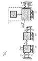
特に、機械的に連結され、第1方向yに沿って振動する3質量体構成を備えたマイクロマシニングによるジャイロスコープを開示している。かかる三質量体振動スキームでは、図1で示すように、質量体m1は質量体m2及び基板に連結され、質量体m2は質量体m3及び基板に連結される。また、質量体m3は、検出部msenseを駆動する。質量体m3は、第2質量体m2を介してのみ質量体m1に機械的に連結されている。 In particular, a micromachining gyroscope with a three mass configuration that is mechanically coupled and vibrates along a first direction y is disclosed. In the three-mass body vibration scheme, as shown in FIG. 1, the mass body m1 is connected to the mass body m2 and the substrate, and the mass body m2 is connected to the mass body m3 and the substrate. The mass body m3 drives the detection unit m sense . The mass body m3 is mechanically coupled to the mass body m1 only through the second mass body m2.
質量体m1はアクチュエータによって駆動されるが、通常は静電気的に駆動される。低電圧では櫛歯アクチュエータを使用可能であるが、より低電圧で動作するので、平行板アクチュエータを使用するのが好ましい場合もある。かかる平行板アクチュエータは、電力効率に優れるが、非線形挙動に起因して大きな変位を提供することができない。しかしながら、後述するように、質量体m1の運動と質量体m3の運動との間の機械的増幅率に起因して、平行板アクチュエータの小さい変位を増幅して、適度に大きい第3質量体m3の振幅が得られる。増加した振幅は、例えば数マイクロメートルである場合がある。 Although the mass body m1 is driven by an actuator, it is normally driven electrostatically. Although comb actuators can be used at low voltages, it may be preferable to use parallel plate actuators because they operate at lower voltages. Such a parallel plate actuator is excellent in power efficiency, but cannot provide a large displacement due to non-linear behavior. However, as will be described later, due to the mechanical amplification factor between the motion of the mass body m1 and the motion of the mass body m3, a small displacement of the parallel plate actuator is amplified to provide a reasonably large third mass body m3. Is obtained. The increased amplitude may be, for example, a few micrometers.
第3質量体m3は、外的な回転の際にコリオリ力を作り出す振動質量体として使用することができる。質量体m3の偏差は、駆動質量体m1、m2及びm3が振動する方向に沿った方向xに垂直な方向y方向に運動する質量体msenseによって検出する。この質量体msenseは、図1に示す構成では質量体m3driveに直接連結され、それ自体は駆動質量体m3の一部である。 The third mass body m3 can be used as a vibrating mass body that creates a Coriolis force during external rotation. The deviation of the mass body m3 is detected by the mass body m sense that moves in the direction y perpendicular to the direction x along the direction in which the driving mass bodies m1, m2, and m3 vibrate. The mass m sense, in the configuration shown in FIG. 1 is coupled directly to the mass m 3Drive, is itself a part of the driving mass m3.
質量体m1,m2,m3の質量、ばね定数k1,k2,k3,k12,k23並びに減衰レベルb1及びb2の値は、質量体m3についての、大きくて周波数範囲(例えば50Hz以上)で平坦な変位応答、及び、質量体m3の平坦な周波数応答での質量体m1とm3との間の機械的増幅率が得られるように設計される。したがって、質量体m1の振幅は小さくてもよく、通常200nm未満であり、さらに100nm未満でもよい。上述のように、このm1の小さい振幅はアクチュエータ(例えば平行板アクチュエータ又は櫛歯アクチュエータ)の低電圧駆動を可能にする。したがって、質量体m3のアクチュエータに対する応答は、いかなる外部回路も必要とすることなく頑強となり、全体の電力消費が低下することとなる。 The masses of the mass bodies m1, m2, and m3, the spring constants k1, k2, k3, k12, and k23 and the values of the attenuation levels b1 and b2 are large and flat displacements in the frequency range (for example, 50 Hz or more) of the mass body m3. The response and the mechanical gain between the masses m1 and m3 at the flat frequency response of the mass m3 are designed. Therefore, the amplitude of the mass m1 may be small, usually less than 200 nm, and even less than 100 nm. As described above, this small amplitude of m1 enables low-voltage driving of an actuator (for example, a parallel plate actuator or a comb-tooth actuator). Therefore, the response of the mass m3 to the actuator is robust without requiring any external circuit, and the overall power consumption is reduced.
図1では、質量体m3は基板に連結されなかったが、図2は、質量体m3が基板にも機械的に連結される別の実施形態を示す。この連結は、ばねk3及び減衰b3によってモデル化される。このような構成は、マイクロマシニングによるジャイロスコープの製造に起因する欠陥に適合するであろう。ばねk1及びk3が同様の形状で設計され、さらに、プロセスに関連する欠陥がある場合、すべてのばねk1,k2,k3,k12,k23が同程度の影響を受ける。さらに、すべての質量体m1、m2及びm3を基板に固定することで、一端が飛び出した質量体の座屈/屈曲に関する機械的応力が最小化すると共に、より大きく、より平坦なデバイスが可能となる。 In FIG. 1, the mass body m3 was not connected to the substrate, but FIG. 2 shows another embodiment in which the mass body m3 is also mechanically connected to the substrate. This connection is modeled by a spring k3 and a damping b3. Such a configuration would be compatible with defects resulting from the manufacture of gyroscopes by micromachining. If the springs k1 and k3 are designed with similar shapes and there are process-related defects, all springs k1, k2, k3, k12, k23 are affected to the same extent. Furthermore, by fixing all the mass bodies m1, m2 and m3 to the substrate, the mechanical stress related to the buckling / bending of the mass body protruding from one end is minimized, and a larger and flatter device is possible. Become.
図2に示す機械的なシステムは、下記の3つの式(1)でモデル化することができる。 The mechanical system shown in FIG. 2 can be modeled by the following three equations (1).

これらの3つの式から、各質量体m1、m2及びm3の変位応答を下記の式(2)のように解析的に得ることができる。 From these three equations, displacement responses of the mass bodies m1, m2, and m3 can be analytically obtained as in the following equation (2).
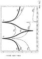
図3は、連結した三質量体の振動構成の共振挙動を示す。駆動力の周波数は掃引され、駆動された質量体の変位はDC変位に関連して測定される。したがって、図3のy軸は、振動ピークの品質係数を表す。応答ピークf1とf3との間で、実質的に平坦な応答領域が得られる。これら2つの共振ピークf1及びf3は、質量体m2の共振周波数が両共振ピークのいずれより大きいように選択された場合には、質量m1及びm3によって決定する。 FIG. 3 shows the resonant behavior of the vibration configuration of the connected three mass bodies. The frequency of the driving force is swept and the displacement of the driven mass is measured in relation to the DC displacement. Therefore, the y-axis in FIG. 3 represents the quality factor of the vibration peak. A substantially flat response region is obtained between the response peaks f1 and f3. These two resonance peaks f1 and f3 are determined by the masses m1 and m3 when the resonance frequency of the mass m2 is selected to be greater than either of the resonance peaks.
質量体m3の平坦で大きい応答、及び、質量体m1と質量体m3との間の機械的増幅率を達成するために、次の設計方法を適用する。第1に、質量体m2は非運動剛体であり、k2は無限であると仮定する。このとき、質量体m1の運動と質量体m3の運動とは別個に決定することができる。次に、質量体m1及び質量体m3のそれぞれの共振周波数f1及びf2は、下記の式(3)に示すように質量体m2が全く影響を与えないことを仮定して、互いに等しいとみなされる。 In order to achieve the flat and large response of the mass m3 and the mechanical gain between the mass m1 and the mass m3, the following design method is applied. First, assume that the mass m2 is a non-motion rigid body and k2 is infinite. At this time, the motion of the mass body m1 and the motion of the mass body m3 can be determined separately. Next, the respective resonance frequencies f1 and f2 of the mass body m1 and the mass body m3 are regarded as equal to each other on the assumption that the mass body m2 has no influence as shown in the following formula (3). .
減衰レベルb1及びb2が充分小さく、かつ、基板に連結されている(b3)場合、有限のk2の値は、質量体m1の共振周波数f1及び質量体m3の共振周波数f3が互いに分離し、両者の間で頑強な応答プラトーを形成すると共に、質量体m1と質量体m3との間に機械的増幅率を形成する。質量体m1及び質量体m3の共振周波数の分離と、プラトーでの質量体m3の応答レベルは、k2の値に依存する。k2が大きいほど、分離は小さく、応答は大きくなる。 When the attenuation levels b1 and b2 are sufficiently small and connected to the substrate (b3), the finite k2 value is such that the resonance frequency f1 of the mass m1 and the resonance frequency f3 of the mass m3 are separated from each other. A strong response plateau is formed between the mass bodies m1 and m3, and a mechanical amplification factor is formed between the mass bodies m1 and m3. The separation of the resonance frequencies of the mass bodies m1 and m3 and the response level of the mass body m3 at the plateau depend on the value of k2. The larger k2, the smaller the separation and the greater the response.
この機械的増幅率は、ジャイロスコープが動作する環境の真空レベル、又は個々のピークの品質係数を増加させることにより、さらに向上させることができる。 This mechanical gain can be further improved by increasing the vacuum level of the environment in which the gyroscope operates or the quality factor of the individual peaks.
機械的増幅率は質量体m1から質量体m3に向かって最も大きくなるが、質量体m1の反共振周波数の位置は、k1を変化させることにより調整することができる。平行板アクチュエータを使用して質量体m1を駆動する場合、k1の値を容易に調整することができる。しかしながら、アプリケーションの観点から、質量体m1の反共振周波数で動作しない方が好ましい場合もある。なぜなら、質量体m1が不安定となるからである。その場合、ジャイロスコープは、質量体m1の反共振周波数から僅かに隔てた周波数で動作し、質量体m1から質量体m3までの機械的増幅率は、真空レベルに関わらず約20〜30であろう。 The mechanical amplification factor becomes the largest from the mass body m1 toward the mass body m3, but the position of the anti-resonance frequency of the mass body m1 can be adjusted by changing k1. When the mass body m1 is driven using the parallel plate actuator, the value of k1 can be easily adjusted. However, it may be preferable not to operate at the anti-resonance frequency of the mass body m1 from the viewpoint of application. This is because the mass body m1 becomes unstable. In this case, the gyroscope operates at a frequency slightly separated from the anti-resonance frequency of the mass body m1, and the mechanical amplification factor from the mass body m1 to the mass body m3 is about 20 to 30 regardless of the vacuum level. Let's go.
減衰レベルb1,b2(及び存在する場合はb3)又は各共振ピークf1及びf3の品質係数は、ジャイロスコープの動作に重要な役割を担っている。品質係数が充分に大きくない場合、連結は生じず、プラトーを形成することもできない。 The attenuation levels b1, b2 (and b3 if present) or the quality factor of each resonance peak f1 and f3 play an important role in the operation of the gyroscope. If the quality factor is not large enough, no connection occurs and no plateau can be formed.
共振周波数f1及びf2の品質係数の選択は、設計基準である。k2が大きいほど、両方の共振周波数の品質係数は大きい必要がある。質量体m2を介して連結される場合、これらの品質係数の値は、ばね定数k2の有限の値に起因して、質量体m1及び質量体m3の共振周波数f1とf3との間のプラトーの平均周波数に対する質量体m2の共振周波数の比、よりも大まかに言って1桁大きい必要がある。 The selection of the quality factor for the resonant frequencies f1 and f2 is a design criterion. The larger the k2, the higher the quality factor of both resonance frequencies. When coupled through the mass m2, these quality factor values are due to the plateau between the resonance frequencies f1 and f3 of the mass m1 and the mass m3 due to the finite value of the spring constant k2. Roughly an order of magnitude higher than the ratio of the resonant frequency of the mass m2 to the average frequency.
質量体m1の反共振周波数の位置は、プラトーの中間地点である必要はない。この位置は、質量m1の質量m3に対する比に依存するが、k1を変化させることで調整可能である。それゆえ、初期の設定段階で、質量体1の共振周波数及び質量体3の共振周波数は互いにf1〜f3に一致するが、質量体m2が非運動物体であると仮定すると、最終的には変化したk1に起因して式(3)が有効である必要はない。
The position of the anti-resonance frequency of the mass body m1 does not have to be an intermediate point of the plateau. This position depends on the ratio of mass m1 to mass m3, but can be adjusted by changing k1. Therefore, at the initial setting stage, the resonance frequency of the mass body 1 and the resonance frequency of the
質量体1と質量体3との間の機械的増幅率は動作周波数に依存する。動作周波数が質量体m1の反共振位置での周波数である場合、増幅率は最大となる。しかしながら、この状況は、質量体m1の運動に不安定性をもたらす可能性がある。反共振から僅かに隔てて動作することが提案されている。この場合、機械的増幅率は現実的に20〜30が可能である。
The mechanical gain between the mass body 1 and the
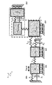
図4、図5及び図6は、代替の実施形態を示す。振動するジャイロスコープ内で1−DOF振動子を使用する場合であれば、提案した三質量体連結振動技術を使用可能である。分離した、又は分離していない検出スキーム及び駆動スキーム並びに音叉トポロジーを使用可能である。さらに、この三質量体振動トポロジーをジャイロスコープの検出部内で使用して、大きいバンド幅及び増幅された感度を達成可能である。 4, 5 and 6 show an alternative embodiment. If the 1-DOF vibrator is used in a vibrating gyroscope, the proposed three-mass coupled vibration technique can be used. Separate and non-separated detection and drive schemes and tuning fork topologies can be used. Furthermore, this three-mass vibration topology can be used in the gyroscope's detector to achieve large bandwidth and amplified sensitivity.
図4は、3つの駆動質量体m1、m2及びm3を備え、m1は基板に(k1,b1)、及び、質量体m2に(k12)連結され、m2は基板に(k2,b2)、及び、質量体m3に(k23)に連結され、質量体m3は、分離質量体mdecouplingを介して検出質量体msensを駆動するようにしたマイクロマシニングによるジャイロスコープを示す。 FIG. 4 comprises three drive masses m1, m2 and m3, where m1 is connected to the substrate (k1, b1) and to the mass m2 (k12), m2 is connected to the substrate (k2, b2), and The mass body m3 is connected to the mass body m3 at (k23), and the mass body m3 is a micromachining gyroscope that drives the detection mass body m sens via the separation mass body m decoupling .
図5は、3つの駆動質量体m1、m2及びm3を備え、m1は基板に(k1,b1)、及び、質量体m2に(k12)連結され、m2は基板に(k2,b2)、及び、質量体m3に(k23)連結され、質量体m3は、分離質量体mdecouplingを介して検出質量体msensを駆動するようにしたマイクロマシニングによるジャイロスコープを示す。この実施形態ではまた、検出質量体msensは、3つの質量体msens_1,msens_2,msens_3が連結されたものとして構成され、質量体msens_2は、基板及び質量体msens_2に連結され、質量体msens_2は、基板及び質量体msens_3に連結されている。この構成では、駆動質量体についての安定した振動周波数範囲が得られ、質量体m1の運動は質量体m3に向かって機械的に増幅されると共に、安定な検出周波数帯が得られ、質量体msens_1の運動は質量体msens_3に向かって機械的に増幅される。 FIG. 5 comprises three drive masses m1, m2 and m3, m1 connected to the substrate (k1, b1) and to the mass m2 (k12), m2 to the substrate (k2, b2), and The mass body m3 is connected to the mass body m3 (k23), and the mass body m3 is a micromachining gyroscope that drives the detection mass body m sens via the separation mass body m decoupling . Also in this embodiment, the sensing mass m sens comprises three masses m sens_1, m sens_2, m sens_3 is configured as being connected, the mass m Sens_2 is connected to the substrate and the mass m Sens_2, The mass body m sens_ 2 is connected to the substrate and the mass body m sens_ 3 . In this configuration, a stable vibration frequency range for the driving mass body is obtained, the motion of the mass body m1 is mechanically amplified toward the mass body m3, and a stable detection frequency band is obtained. movement of sens_1 is mechanically amplified towards the mass m sens_3.
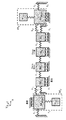
図6は、音叉構成で3つの駆動質量体m1、m2及びm3を備え、質量体m1は基板に(k1,b1)、及び、質量体m2に(k12)連結され、m2は、基板に(k2,b2)、及び、質量体m3に(k23)連結され、質量体m3は、分離質量体mdecouplingを介して検出質量体msensを駆動するようにしたマイクロマシニングによるジャイロスコープを示す。それはさらに、第2の組の、3つの駆動質量体m1’、m2’及びm3’を備え、m1’は基板及び質量体m2’に(k12’)連結され、m2’は基板及び質量体m3’に(k23’)連結され、質量体m3’は検出質量体msens’を駆動する。機械的に連結したm1、m2及びm3と、m1’、m2’及びm3’の両方の組が、同じアクチュエータによって駆動される。 FIG. 6 shows a tuning fork configuration with three driving masses m1, m2 and m3, which is connected to the substrate (k1, b1) and to the mass m2 (k12), and m2 is connected to the substrate ( k2, b2) and (k23) connected to the mass body m3, and the mass body m3 shows a gyroscope by micromachining that drives the detection mass body m sens via the separation mass body m decoupling . It further comprises a second set of three drive masses m1 ', m2' and m3 ', m1' connected (k12 ') to the substrate and mass m2', m2 'being the substrate and mass m3 To (k23 ') and the mass m3' drives the detection mass m sens' . Both mechanically connected m1, m2 and m3 and m1 ′, m2 ′ and m3 ′ sets are driven by the same actuator.
多くの実施形態の例が考慮される。1つの実施形態の例では、マイクロマシニングによるジャイロスコープは、基板と、第1方向に沿って振動するように構成された3つの質量体とを含んでもよい。第1質量体m1は、基板に機械的に連結されてもよく、第2質量体m2は、第1質量体及び基板に機械的に連結されてもよく、第3質量体m3は第2質量体m2に機械的に連結されてもよい。ジャイロスコープは、次の式、[(k2+k12+k23)/m2]≫([(k1+k12)/m1]〜[(k23)/m3])のように規定してもよい。ここで、m1,m2,m3は、それぞれ質量体m1、m2及びm3の重さであり、k1,k2は、それぞれの質量体と基板との間の機械的接続部のばね定数であり、k12,k23は、それぞれ第2質量体と第1質量体、第2質量体と第3質量体との間の機械的接続部のばね定数である。 Many example embodiments are contemplated. In one example embodiment, a micromachined gyroscope may include a substrate and three masses configured to vibrate along a first direction. The first mass m1 may be mechanically coupled to the substrate, the second mass m2 may be mechanically coupled to the first mass and the substrate, and the third mass m3 may be the second mass. It may be mechanically coupled to the body m2. The gyroscope may be defined as follows: [(k2 + k12 + k23) / m2] >> ([(k1 + k12) / m1] to [(k23) / m3]). Here, m1, m2, and m3 are the weights of the mass bodies m1, m2, and m3, respectively, k1 and k2 are the spring constants of the mechanical connection portions between the respective mass bodies and the substrate, and k12 , K23 are spring constants of mechanical connection portions between the second mass body and the first mass body, and the second mass body and the third mass body, respectively.
いくつかの実施形態では、第3質量体m3は基板に機械的に連結されてもよく、次の関係、[(k2+k12+k23)/m2]≫[(k1+k12)/m1]〜[k3+k23)/m3]が存在してもよい。ここで、k3は、質量体m3と基板との間の機械的接続部のばね定数である。 In some embodiments, the third mass m3 may be mechanically coupled to the substrate and has the following relationship: [(k2 + k12 + k23) / m2] >> [(k1 + k12) / m1] to [k3 + k23) / m3] May be present. Here, k3 is a spring constant of the mechanical connection portion between the mass body m3 and the substrate.
いくつかの実施形態では、3つの質量体は駆動質量体である。ジャイロスコープはさらに、第1質量体m1を駆動するための駆動手段を含んでもよい。駆動手段は、例えば、1つ以上の平行板静電アクチュエータでもよい。 In some embodiments, the three masses are drive masses. The gyroscope may further include driving means for driving the first mass body m1. The drive means may be, for example, one or more parallel plate electrostatic actuators.
いくつかの実施形態では、3つの質量体はジャイロスコープが回転する際に運動するように構成された検出質量体でもよい。 In some embodiments, the three masses may be detection masses that are configured to move as the gyroscope rotates.
いくつかの実施形態では、ジャイロスコープはさらに、3質量体構成の複製組を含んでもよい。その複製組は、3質量体構成と逆位相で第1方向に沿って振動するように構成してもよい。 In some embodiments, the gyroscope may further include a three mass configuration replica set. The replica set may be configured to vibrate along the first direction in opposite phase to the three mass configuration.
いくつかの実施形態では、質量体が直線的に振動するように構成してもよい。 In some embodiments, the mass may be configured to vibrate linearly.
別の実施形態の例では、マイクロマシニングによるジャイロスコープの設計方法が、[(k1+k12)/m1]〜[k3+k23)/m3]を満たすようにm1、m3、k1及びk3を選択する工程を含んでもよい。その方法はさらに、動作中に、[(k2+k12+k23)/m2]≫[(k1+k12)/m1]>[k3+k23)/m3]を満たすようにm2、k2を選択する工程を含んでもよい。 In another example embodiment, the micromachining gyroscope design method may include selecting m1, m3, k1, and k3 so as to satisfy [(k1 + k12) / m1] to [k3 + k23) / m3]. Good. The method may further include the step of selecting m2 and k2 to satisfy [(k2 + k12 + k23) / m2] >> [(k1 + k12) / m1]> [k3 + k23) / m3] during operation.
いくつかの実施形態では、その方法はさらに、質量体m1の運動と質量体m3の運動との間の機械的増幅率を選択する工程と、k2をこの所望の機械的増幅率を考慮した値とする工程とを含んでもよい。 In some embodiments, the method further includes selecting a mechanical gain between the motion of the mass m1 and the motion of the mass m3, and k2 is a value that takes into account the desired mechanical gain. And a step of
Claims (9)
第1質量体は、基板に機械的に連結され、
第2質量体は、第1質量体及び基板に機械的に連結され、
第3質量体は、第2質量体に機械的に連結され、
次の関係、
[(k2+k12+k23)/m2]≫([(k1+k12)/m1]〜[(k23)/m3])
が存在し、
m1、m2、m3は、それぞれ第1質量体、第2質量体及び第3質量体の重さであり、
k1、k2及びk3は、それぞれ第1質量体、第2質量体又は第2質量体と基板との間の機械的接続部のばね定数であり、
k12、k23は、それぞれ第2質量体と第1質量体又は第3質量体との間の機械的接続部のばね定数であるようにした、マイクロマシニングによるジャイロスコープ。 A substrate and three mass bodies configured to vibrate along a first direction;
The first mass is mechanically coupled to the substrate;
The second mass body is mechanically coupled to the first mass body and the substrate,
The third mass body is mechanically coupled to the second mass body,
The following relationship,
[(K2 + k12 + k23) / m2] >> ([(k1 + k12) / m1] to [(k23) / m3])
Exists,
m1, m2, and m3 are the weights of the first mass body, the second mass body, and the third mass body, respectively.
k1, k2 and k3 are the spring constants of the mechanical connection between the first mass body, the second mass body or the second mass body and the substrate, respectively,
k12 and k23 are micromachining gyroscopes, respectively, which are spring constants of mechanical connection portions between the second mass body and the first mass body or the third mass body.
次の関係、
[(k2+k12+k23)/m2]≫[(k1+k12)/m1]〜[k3+k23)/m3]
が存在し、
m1、m2、m3は、それぞれ第1質量体、第2質量体及び第3質量体の重さであり、
k1、k2及びk3は、それぞれ第1質量体、第2質量体又は第2質量体と基板との間の機械的接続部のばね定数であり、
k12、k23は、それぞれ第2質量体と第1質量体又は第3質量体との間の機械的接続部のばね定数であるようにした、マイクロマシニングによるジャイロスコープ。 The third mass is mechanically coupled to the substrate;
The following relationship,
[(K2 + k12 + k23) / m2] >> [(k1 + k12) / m1] to [k3 + k23) / m3]
Exists,
m1, m2, and m3 are the weights of the first mass body, the second mass body, and the third mass body, respectively.
k1, k2 and k3 are the spring constants of the mechanical connection between the first mass body, the second mass body or the second mass body and the substrate, respectively,
k12 and k23 are micromachining gyroscopes, respectively, which are spring constants of mechanical connection portions between the second mass body and the first mass body or the third mass body.
第1質量体を駆動するための駆動手段をさらに備えた、請求項1又は2に記載のマイクロマシニングによるジャイロスコープ。 The three mass bodies are drive mass bodies,
The micromachining gyroscope according to claim 1, further comprising a driving unit for driving the first mass body.
[(k1+k12)/m1]〜[k3+k23)/m3]
を満たすように選択する工程と、
第2質量体、及び、第2質量体と基板との間のばね定数を、動作中に、
[(k2+k12+k23)/m2]≫[(k1+k12)/m1]>[k3+k23)/m3]
を満たすように選択する工程とを含み、
m1、m2、m3は、それぞれ第1質量体、第2質量体及び第3質量体の重さであり、
k1、k2及びk3は、それぞれ第1質量体、第2質量体又は第2質量体と基板との間の機械的接続部のばね定数であり、
k12、k23は、それぞれ第2質量体と第1質量体又は第3質量体との間の機械的接続部のばね定数であるようにした、請求項1〜7のいずれか1項に記載のマイクロマシニングによるジャイロスコープを設計するための方法。 The first mass body, the spring constant between the first mass body and the substrate, the third mass body, and the spring constant between the third mass body and the substrate,
[(K1 + k12) / m1] to [k3 + k23) / m3]
Selecting to satisfy
During operation, the second mass and the spring constant between the second mass and the substrate are
[(K2 + k12 + k23) / m2] >> [(k1 + k12) / m1]> [k3 + k23) / m3]
Selecting to satisfy
m1, m2, and m3 are the weights of the first mass body, the second mass body, and the third mass body, respectively.
k1, k2 and k3 are the spring constants of the mechanical connection between the first mass body, the second mass body or the second mass body and the substrate, respectively,
k12 and k23 are the spring constants of the mechanical connection part between a 2nd mass body and a 1st mass body, or a 3rd mass body, respectively. A method for designing a micromachining gyroscope.
第2質量体と基板との間のばね定数を、この所望の機械的増幅率を考慮した値とする工程とをさらに含む、請求項8に記載の方法。 Selecting a mechanical gain between the motion of the first mass and the motion of the third mass;
The method according to claim 8, further comprising: setting a spring constant between the second mass body and the substrate to a value in consideration of the desired mechanical amplification factor.
Applications Claiming Priority (2)
| Application Number | Priority Date | Filing Date | Title |
|---|---|---|---|
| US201161534146P | 2011-09-13 | 2011-09-13 | |
| US61/534,146 | 2011-09-13 |
Publications (2)
| Publication Number | Publication Date |
|---|---|
| JP2013061338A true JP2013061338A (en) | 2013-04-04 |
| JP2013061338A5 JP2013061338A5 (en) | 2015-11-05 |
Family
ID=46762913
Family Applications (1)
| Application Number | Title | Priority Date | Filing Date |
|---|---|---|---|
| JP2012200751A Pending JP2013061338A (en) | 2011-09-13 | 2012-09-12 | Three-mass coupled oscillation technique for mechanically robust micromachined gyroscope |
Country Status (3)
| Country | Link |
|---|---|
| US (1) | US8955381B2 (en) |
| EP (1) | EP2570770B1 (en) |
| JP (1) | JP2013061338A (en) |
Families Citing this family (5)
| Publication number | Priority date | Publication date | Assignee | Title |
|---|---|---|---|---|
| US10914584B2 (en) | 2011-09-16 | 2021-02-09 | Invensense, Inc. | Drive and sense balanced, semi-coupled 3-axis gyroscope |
| US8833162B2 (en) | 2011-09-16 | 2014-09-16 | Invensense, Inc. | Micromachined gyroscope including a guided mass system |
| US9863769B2 (en) | 2011-09-16 | 2018-01-09 | Invensense, Inc. | MEMS sensor with decoupled drive system |
| US9958271B2 (en) | 2014-01-21 | 2018-05-01 | Invensense, Inc. | Configuration to reduce non-linear motion |
| EP4166902A1 (en) * | 2014-05-21 | 2023-04-19 | InvenSense, Inc. | Mems sensor with decoupled drive system |
Family Cites Families (5)
| Publication number | Priority date | Publication date | Assignee | Title |
|---|---|---|---|---|
| DE4414237A1 (en) * | 1994-04-23 | 1995-10-26 | Bosch Gmbh Robert | Micromechanical vibrator of an oscillation gyrometer |
| DE19827688A1 (en) * | 1997-06-20 | 1999-01-28 | Aisin Seiki | Angular velocity sensor |
| US7377167B2 (en) * | 2004-02-27 | 2008-05-27 | The Regents Of The University Of California | Nonresonant micromachined gyroscopes with structural mode-decoupling |
| US8020441B2 (en) * | 2008-02-05 | 2011-09-20 | Invensense, Inc. | Dual mode sensing for vibratory gyroscope |
| JP2008281485A (en) * | 2007-05-11 | 2008-11-20 | Toyota Motor Corp | Angular velocity detector |
-
2012
- 2012-08-31 EP EP12182539.2A patent/EP2570770B1/en active Active
- 2012-09-12 JP JP2012200751A patent/JP2013061338A/en active Pending
- 2012-09-13 US US13/613,770 patent/US8955381B2/en active Active
Also Published As
| Publication number | Publication date |
|---|---|
| EP2570770A3 (en) | 2016-03-30 |
| EP2570770B1 (en) | 2021-06-23 |
| EP2570770A2 (en) | 2013-03-20 |
| US20130061673A1 (en) | 2013-03-14 |
| US8955381B2 (en) | 2015-02-17 |
Similar Documents
| Publication | Publication Date | Title |
|---|---|---|
| US10168154B2 (en) | Integrated microelectromechanical gyroscope with improved driving structure | |
| US6860151B2 (en) | Methods and systems for controlling movement within MEMS structures | |
| JP6172272B2 (en) | Improved vibratory gyroscope | |
| JP4433747B2 (en) | Angular velocity detector | |
| JP5991431B2 (en) | Improved vibratory gyroscope | |
| JP6011725B2 (en) | Improved resonator | |
| JP2007530918A (en) | Flexible vibration type micro electromechanical device | |
| JP2013061338A (en) | Three-mass coupled oscillation technique for mechanically robust micromachined gyroscope | |
| JP2012173055A (en) | Physical quantity sensor and electronic apparatus | |
| EP3249354B1 (en) | Systems and methods for a tuned mass damper in mems resonators | |
| JP5518177B2 (en) | Micromechanical system and method for manufacturing a micromechanical system | |
| JP2008014727A (en) | Acceleration/angular velocity sensor | |
| US20160327390A1 (en) | Method and apparatus for decoupling environmental and modal dependencies in inertial measurement devices | |
| US9509278B2 (en) | Rotational MEMS resonator for oscillator applications | |
| JP6632726B2 (en) | Micromechanical yaw rate sensor and method of manufacturing the same | |
| JP2010008300A (en) | Inertia sensor | |
| Alshehri et al. | Two-mass MEMS velocity sensor: Internal feedback loop design | |
| JP2007047167A (en) | Nodal position correction method of vibrating beam | |
| JPH036445B2 (en) |
Legal Events
| Date | Code | Title | Description |
|---|---|---|---|
| A521 | Written amendment |
Free format text: JAPANESE INTERMEDIATE CODE: A523 Effective date: 20150908 |
|
| A621 | Written request for application examination |
Free format text: JAPANESE INTERMEDIATE CODE: A621 Effective date: 20150908 |
|
| A131 | Notification of reasons for refusal |
Free format text: JAPANESE INTERMEDIATE CODE: A131 Effective date: 20160726 |
|
| A977 | Report on retrieval |
Free format text: JAPANESE INTERMEDIATE CODE: A971007 Effective date: 20160727 |
|
| A601 | Written request for extension of time |
Free format text: JAPANESE INTERMEDIATE CODE: A601 Effective date: 20161014 |
|
| A601 | Written request for extension of time |
Free format text: JAPANESE INTERMEDIATE CODE: A601 Effective date: 20161214 |
|
| A02 | Decision of refusal |
Free format text: JAPANESE INTERMEDIATE CODE: A02 Effective date: 20170321 |