JP2013055437A - Image forming device - Google Patents

Image forming device Download PDF

Info

Publication number
JP2013055437A
JP2013055437A JP2011191222A JP2011191222A JP2013055437A JP 2013055437 A JP2013055437 A JP 2013055437A JP 2011191222 A JP2011191222 A JP 2011191222A JP 2011191222 A JP2011191222 A JP 2011191222A JP 2013055437 A JP2013055437 A JP 2013055437A
Authority
JP
Japan
Prior art keywords
document
adf
image forming
forming apparatus
pressing portion
Prior art date
Legal status (The legal status is an assumption and is not a legal conclusion. Google has not performed a legal analysis and makes no representation as to the accuracy of the status listed.)
Pending
Application number
JP2011191222A
Other languages
Japanese (ja)
Other versions
JP2013055437A5 (en
Inventor
Shinro Umezawa
梅澤  眞郎
Current Assignee (The listed assignees may be inaccurate. Google has not performed a legal analysis and makes no representation or warranty as to the accuracy of the list.)
Canon Inc
Original Assignee
Canon Inc
Priority date (The priority date is an assumption and is not a legal conclusion. Google has not performed a legal analysis and makes no representation as to the accuracy of the date listed.)
Filing date
Publication date
Application filed by Canon Inc filed Critical Canon Inc
Priority to JP2011191222A priority Critical patent/JP2013055437A/en
Publication of JP2013055437A publication Critical patent/JP2013055437A/en
Publication of JP2013055437A5 publication Critical patent/JP2013055437A5/ja
Pending legal-status Critical Current

Links

Images

Landscapes

  • Facsimile Scanning Arrangements (AREA)
  • Facsimiles In General (AREA)

Abstract

PROBLEM TO BE SOLVED: To provide an image forming device for improving opening/closing operability of a document pressing part.SOLUTION: An image forming device having an ADF 200 that is configured to be openable/closable with respect to an image forming device body 100 having a document reading device body 100a and is provided with a document pressing part 200a for pressing a document placed on a document platen 111 has a link mechanism 7 that allows an ADF rotation fulcrum 24 supporting the ADF 200 having the document pressing part 200a in an openable/closable manner to move upward with reference to the document platen 111 in conjunction with an opening operation of the ADF 200.

Description

本発明は原稿読取装置を有し、この原稿読取装置により読み取られた原稿を出力する複写機、プリンタ等の画像形成装置に関するものである。   The present invention relates to an image forming apparatus such as a copying machine or a printer that has a document reading device and outputs a document read by the document reading device.

従来、原稿読取装置では原稿台に載置された原稿を押圧する圧板部は装置後側に設けたヒンジ部を回転支点として圧板部の手前を持ち上げることで原稿台を開放していた。   2. Description of the Related Art Conventionally, in a document reading apparatus, a platen that presses a document placed on a document table is opened by lifting the front of the platen with a hinge provided on the rear side of the device as a rotation fulcrum.

また、原稿を自動的に搬送し読取を可能としたADF(Auto Document Feeder;自動原稿搬送装置)等の機能を有する装置の圧板部は一般的に重量があるものが多い。ヒンジ部にカムや圧縮バネにより構成された保持機構により、圧板部を任意の角度において保持する構成が一般的であった(特許文献1参照)。   In general, the platen portion of an apparatus having a function such as an ADF (Auto Document Feeder) that automatically conveys and reads a document is generally heavy. A configuration in which the pressure plate portion is held at an arbitrary angle by a holding mechanism constituted by a cam or a compression spring at the hinge portion is common (see Patent Document 1).

例えば、背の低いユーザや車椅子を利用するユーザ用に先端に鍵形状を有する棒状のハンドル等を圧板部に取り付けて圧板部を持ち上げる補助器具として用意したものもある(特許文献2参照)。   For example, there is a device that is prepared as an auxiliary device for lifting a pressure plate by attaching a bar-shaped handle having a key shape at the tip to the pressure plate for a short user or a user using a wheelchair (see Patent Document 2).

特開2009−071804号公報JP 2009-071804 A 特開2007−078855号公報JP 2007-078855 A

しかしながら、特許文献1の技術では、背の低いユーザや車椅子を利用するユーザ等にとっては、一度持ち上げられた圧板部の先端位置は自分の背丈よりも高くなる場合があり、圧板部の開閉操作がし難いといった問題があった。   However, in the technique of Patent Document 1, for a short user, a user who uses a wheelchair, and the like, the tip position of the pressure plate portion once lifted may be higher than his / her height, and the opening / closing operation of the pressure plate portion may be performed. There was a problem that it was difficult.

特許文献2の技術は、この問題を解決し得る一例であり、操作力に関しては、バネやダンパ等の補助機構を付加した構成もある。一般的に従来のADFは開閉操作に大きな操作力を要するものや、圧板部の開放角度が一定角度以下になるとADFの自重を支えきれずに一気に降下するものがあった。   The technique of Patent Document 2 is an example that can solve this problem, and there is a configuration in which an auxiliary mechanism such as a spring or a damper is added to the operation force. In general, some conventional ADFs require a large operating force for opening and closing operations, and others drop at a time without being able to support the weight of the ADF when the opening angle of the pressure plate part is below a certain angle.

特にコンビニエンスストアや図書館、学校等の公共性の高い場所に設置された画像形成装置は不特定多数のユーザに利用されることが多く、一般的により高い操作性が必要とされる場合が多い。このため、健常者に対する操作性の向上と共に、上記のハンドル等の補助器具を必要とせず、不特定多数のユーザが容易に且つ快適に操作することが可能な画像形成装置が望まれている。   In particular, image forming apparatuses installed in highly public places such as convenience stores, libraries, and schools are often used by an unspecified number of users, and generally higher operability is often required. Therefore, there is a demand for an image forming apparatus that can be easily and comfortably operated by an unspecified number of users, as well as improving the operability for a healthy person, without requiring an auxiliary instrument such as the handle.

本発明は前記課題を解決するものであり、その目的とするところは、原稿押圧部の開閉操作性を向上する画像形成装置を提供するものである。   SUMMARY An advantage of some aspects of the invention is that it provides an image forming apparatus that improves the opening / closing operability of a document pressing portion.

前記目的を達成するための本発明に係る画像形成装置の代表的な構成は、原稿読取装置本体に対して開閉可能に構成され、原稿台に載置された原稿を押圧する原稿押圧部を備えた原稿読取装置を有する画像形成装置において、前記原稿押圧部を開閉可能に支持する支点が、該原稿押圧部の開放動作に連動して前記原稿台を基準として、上方に移動する原稿押圧部保持手段を有することを特徴とする。   In order to achieve the above object, a typical configuration of an image forming apparatus according to the present invention is configured to be openable and closable with respect to a document reading apparatus main body, and includes a document pressing unit that presses a document placed on a document table. In the image forming apparatus having the original reading device, the fulcrum supporting the original pressing portion so as to be openable / closable moves upward with respect to the original table in conjunction with the opening operation of the original pressing portion. It has the means.

上記構成によれば、原稿押圧部を開閉可能に支持する支点が、該原稿押圧部の開放動作に連動して原稿台を基準として、上方に移動することで、原稿押圧部を開閉可能に支持する支点が上方に移動した分だけ原稿台上の操作スペースが拡大し、操作性が向上する。言い換えれば、同じ操作スペースを確保する場合、原稿押圧部の開放角度を小さくすることが可能となる。これにより、背の低いユーザや車椅子を利用するユーザ等が原稿押圧部を開閉操作する場合に自分の手が届く開放角度の範囲内での操作が可能となり、原稿押圧部の開閉操作性を向上することが出来る。   According to the above configuration, the fulcrum that supports the document pressing portion so as to be openable / closable moves upward with respect to the document table in conjunction with the opening operation of the document pressing portion, so that the document pressing portion can be opened / closed. As the fulcrum to be moved moves upward, the operation space on the document table is expanded, and the operability is improved. In other words, when the same operation space is secured, the opening angle of the document pressing portion can be reduced. This makes it possible to operate within the range of the opening angle that can be reached by a short user or a user using a wheelchair to open and close the document pressing unit, improving the opening and closing operability of the document pressing unit. I can do it.

本発明に係る画像形成装置の第1実施形態において、原稿押圧部を閉じた状態を示す外観斜視図である。1 is an external perspective view showing a state in which a document pressing portion is closed in a first embodiment of an image forming apparatus according to the present invention. 第1実施形態において、原稿押圧部を開放した状態を示す外観斜視図である。FIG. 3 is an external perspective view showing a state in which a document pressing portion is opened in the first embodiment. 第1実施形態において、原稿押圧部を閉じた状態を示す側面部分断面図である。FIG. 3 is a side partial cross-sectional view illustrating a state where a document pressing unit is closed in the first embodiment. 第1実施形態において、原稿押圧部を所定角度開放した状態を示す側面部分断面図である。FIG. 3 is a side partial cross-sectional view illustrating a state where a document pressing portion is opened at a predetermined angle in the first embodiment. 第1実施形態において、原稿押圧部を全開した状態を示す側面部分断面図である。In the first embodiment, it is a side partial cross-sectional view showing a state in which a document pressing portion is fully opened. 第1実施形態において、付勢部材の押圧力を調整する様子を示す側面部分断面図である。In 1st Embodiment, it is a side surface fragmentary sectional view which shows a mode that the pressing force of a biasing member is adjusted. 本発明に係る画像形成装置の第2実施形態において、原稿押圧部を閉じた状態を示す外観斜視図である。FIG. 10 is an external perspective view showing a state in which a document pressing portion is closed in the second embodiment of the image forming apparatus according to the present invention. 第2実施形態において、原稿押圧部を開放した状態を示す外観斜視図である。In 2nd Embodiment, it is an external appearance perspective view which shows the state which open | released the original document press part. 本発明に係る画像形成装置の第3実施形態において、原稿押圧部を開放した状態を示す外観斜視図である。FIG. 10 is an external perspective view showing a state in which a document pressing portion is opened in a third embodiment of the image forming apparatus according to the present invention. 第3実施形態において、原稿押圧部を開放した位置状態を示す外観斜視図である。In 3rd Embodiment, it is an external appearance perspective view which shows the position state which open | released the document press part. 本発明に係る画像形成装置の第4実施形態の構成を示す外観斜視図である。It is an external appearance perspective view which shows the structure of 4th Embodiment of the image forming apparatus which concerns on this invention. 第4実施形態の左側リンクユニットの構成を示す断面説明図である。It is sectional explanatory drawing which shows the structure of the left side link unit of 4th Embodiment.

図により本発明に係る画像形成装置の一実施形態を具体的に説明する。   An embodiment of an image forming apparatus according to the present invention will be specifically described with reference to the drawings.

先ず、図1〜図6を用いて本発明に係る画像形成装置の第1実施形態について説明する。   First, a first embodiment of an image forming apparatus according to the present invention will be described with reference to FIGS.

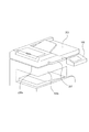
図1〜図6において、画像形成装置本体100の上面には読取原稿をセットする原稿台111が設けられている。原稿台111の上面にはセットされた複数の原稿を自動的に1枚づつ順次、原稿台111に搬送(自動搬送)するADF(Auto Document Feeder;自動原稿搬送装置)200が開閉可能に設けられる。   1 to 6, a document table 111 on which a read document is set is provided on the upper surface of the image forming apparatus main body 100. On the upper surface of the document table 111, an ADF (Auto Document Feeder) 200 that automatically conveys (automatically conveys) a plurality of set documents one by one to the document table 111 is provided to be openable and closable. .

原稿台111に載置された原稿を押圧する原稿押圧部200aを下面に備えたADF200が画像形成装置本体100の上部に設けられた原稿読取装置本体100aに対して開閉可能に設置されている。尚、本実施形態では、原稿読取装置本体100aは画像形成装置本体100の上部に一体的に設けられるため以下の説明では、ADF200が原稿押圧部保持手段となるリンク機構7を介して画像形成装置本体100に対して開閉可能に構成されているとして説明する。   An ADF 200 having a document pressing portion 200a for pressing a document placed on the document table 111 on the lower surface is installed so as to be openable and closable with respect to the document reading apparatus main body 100a provided on the upper part of the image forming apparatus main body 100. In the present embodiment, the document reading apparatus main body 100a is integrally provided on the upper part of the image forming apparatus main body 100. Therefore, in the following description, the ADF 200 is provided via the link mechanism 7 serving as a document pressing portion holding means. The description will be made assuming that the main body 100 is configured to be openable and closable.

図3〜図6に示すように、画像形成装置本体100の左右側面上部にはL字形状のベース3が固定されている。そして、ベース3上に設けられたアーム回動支点21を中心にアーム1が回動可能に設けられている。アーム1上に設けられたリンク回動支点22を中心にリンク2が回動可能に取り付けられている。ADF200は、ベース3に図3の上下方向に形成された長穴3aに沿って移動し得るADF回動支点24及びアーム1に形成された長穴1aに沿って移動し得るスライダ支点23を介して該ADF回動支点24を中心に回動可能に取り付けられている。   As shown in FIGS. 3 to 6, an L-shaped base 3 is fixed to upper left and right side surfaces of the image forming apparatus main body 100. The arm 1 is provided so as to be rotatable around an arm turning fulcrum 21 provided on the base 3. A link 2 is pivotably mounted around a link pivot fulcrum 22 provided on the arm 1. The ADF 200 is connected to the base 3 via an ADF rotation fulcrum 24 that can move along the elongated hole 3a formed in the vertical direction in FIG. 3 and a slider fulcrum 23 that can move along the elongated hole 1a formed in the arm 1. The ADF rotation fulcrum 24 is attached so as to be rotatable.

尚、ベース3に設けられた長穴3aに沿って移動し得るADF回動支点24は、該ADF回動支点24に設けられた軸部材が長穴3a内に挿通され、該軸部材が長穴3aに沿ってスライド自在に移動する。また、アーム1に設けられた長穴1aに沿って移動し得るスライダ支点23は、該スライダ支点23に設けられた軸部材が長穴1a内に挿通され、該軸部材が長穴1aに沿ってスライド自在に移動する。   The ADF rotation fulcrum 24 that can move along the elongated hole 3a provided in the base 3 has a shaft member provided at the ADF rotation fulcrum 24 inserted into the elongated hole 3a. It moves slidably along the hole 3a. Further, the slider fulcrum 23 that can move along the long hole 1a provided in the arm 1 has a shaft member provided at the slider fulcrum 23 inserted into the long hole 1a, and the shaft member extends along the long hole 1a. Move slidably.

本実施形態では、ベース3、アーム1、リンク2によりリンク機構7を構成する。リンク機構7は原稿押圧部200aを有するADF200の画像形成装置本体100に対する開閉動作に連動する。リンク機構7は原稿押圧部200aを有するADF200を画像形成装置本体100に対して開閉可能に保持する原稿押圧部保持手段を構成する。   In the present embodiment, the link mechanism 7 is configured by the base 3, the arm 1, and the link 2. The link mechanism 7 is linked to the opening / closing operation of the ADF 200 having the document pressing portion 200a with respect to the image forming apparatus main body 100. The link mechanism 7 constitutes a document pressing unit holding unit that holds the ADF 200 having the document pressing unit 200a with respect to the image forming apparatus main body 100 so as to be openable and closable.

リンク機構7を構成するアーム1のアーム回動支点21と反対側の端部には、原稿押圧部200aを有するADF200の自重に拮抗する付勢部材となる圧縮バネ4の一端が固定されている。圧縮バネ4の他端は、該圧縮バネ4の押圧力を調整する押圧力調整手段となる調整ネジ6の一端部に設けられた当接部材6aに当接している。   One end of the compression spring 4 serving as an urging member that antagonizes the weight of the ADF 200 having the document pressing portion 200a is fixed to the end portion of the arm 1 constituting the link mechanism 7 opposite to the arm rotation fulcrum 21. . The other end of the compression spring 4 is in contact with a contact member 6 a provided at one end of an adjustment screw 6 that serves as a pressing force adjusting means for adjusting the pressing force of the compression spring 4.

調整ネジ6はADF200の本体フレームに設けられた雌ネジ部200bに回転自在に螺合されている。調整ネジ6には調整ダイアル5の内周面に形成された雌ネジ部が回転自在に螺合されており、調整ダイアル5は、その両端面がADF200の本体フレームに設けられた拘束片200c,200dにより位置が拘束されつつ回転自在に構成される。   The adjustment screw 6 is rotatably screwed into a female screw portion 200b provided on the main body frame of the ADF 200. A female screw portion formed on the inner peripheral surface of the adjustment dial 5 is rotatably screwed to the adjustment screw 6, and the adjustment dial 5 has constraining pieces 200 c, both ends of which are provided on the main body frame of the ADF 200. It is configured to be rotatable while being restrained by the position 200d.

調整ダイアル5を回転させることで調整ネジ6が該調整ダイアル5の回転方向に応じて図3の右方向または左方向に移動する。その結果、圧縮バネ4がアーム1に加える押圧力の調整を可能にしている。   By rotating the adjustment dial 5, the adjustment screw 6 moves to the right or left in FIG. 3 according to the rotation direction of the adjustment dial 5. As a result, the pressing force applied to the arm 1 by the compression spring 4 can be adjusted.

尚、図3〜図6では画像形成装置本体100の左側面側に上記リンク機構7等の原稿押圧部保持手段の構成を有する一例を説明したが、該画像形成装置本体100の右側面側にも左右対称な同様の上記リンク機構7等の原稿押圧部保持手段の構成が設置されている。   3 to 6, an example in which the structure of the document pressing portion holding means such as the link mechanism 7 is provided on the left side of the image forming apparatus main body 100 has been described, but on the right side of the image forming apparatus main body 100. Also, a similar configuration of the document pressing portion holding means such as the above-described link mechanism 7 is provided.

原稿押圧部保持手段を構成するリンク機構7により原稿押圧部200aを有するADF200を画像形成装置本体100に対して開閉可能に支持する。   The ADF 200 having the document pressing portion 200a is supported by the link mechanism 7 constituting the document pressing portion holding means so as to be openable and closable with respect to the image forming apparatus main body 100.

ADF200を画像形成装置本体100に対して開閉可能に支持するADF回動支点24は、ベース3に図3〜図5の上下方向に設けられた長穴3aに沿って上下方向に移動する。ADF回動支点24は、図3〜図5に示すように、原稿押圧部200aを有するADF200の開放動作に連動して原稿台111を基準として上方に移動する。   The ADF rotation fulcrum 24 that supports the ADF 200 with respect to the image forming apparatus main body 100 so as to be openable and closable moves in the vertical direction along a long hole 3a provided in the base 3 in the vertical direction in FIGS. As shown in FIGS. 3 to 5, the ADF rotation fulcrum 24 moves upward with respect to the document table 111 in conjunction with the opening operation of the ADF 200 having the document pressing portion 200 a.

ここで、ユーザが図4に示すように、ADF200を開いて図示しない原稿を原稿台111にセットする場合、ADF200の開放側の端部に設けられたハンドル201に開く力F1を加えて持ち上げる。これにより、図4に示すようにアーム回動支点21を中心にアーム1が図4の反時計回り方向に回動する。アーム1の回動によりリンク2がアーム1上に設けられたリンク回動支点22を中心に図4の時計回り方向に回動しつつベース3に図4の上下方向に設けられた長穴3aに沿ってADF回動支点24がADF200と共に押し上げられて上方に移動する。また、スライダ支点23はアーム1の長穴1aに沿って図4の右方向に移動する。   Here, as shown in FIG. 4, when the user opens the ADF 200 and sets a document (not shown) on the document table 111, the user lifts the handle 201 provided at the open end of the ADF 200 by applying an opening force F1. As a result, as shown in FIG. 4, the arm 1 rotates about the arm rotation fulcrum 21 in the counterclockwise direction of FIG. 4. As the arm 1 rotates, the link 2 rotates around the link rotation fulcrum 22 provided on the arm 1 in the clockwise direction in FIG. The ADF rotation fulcrum 24 is pushed up together with the ADF 200 and moves upward. Further, the slider fulcrum 23 moves along the elongated hole 1a of the arm 1 in the right direction in FIG.

リンク2が回動可能に取り付けられるADF回動支点24はADF200に対して固定位置に設けられている。このため、ADF200は、リンク2が上方に押し上げられるのに伴なって、図4及び図5に示すように、原稿台111を基準として上方に押し上げられながら開放される。図2及び図5に示すように、原稿押圧部200aを有するADF200を画像形成装置本体100に対して全開した状態では、原稿台111を基準として上方に操作スペースGが形成される。   An ADF rotation fulcrum 24 to which the link 2 is rotatably attached is provided at a fixed position with respect to the ADF 200. Therefore, as the link 2 is pushed upward, the ADF 200 is released while being pushed upward with reference to the document table 111 as shown in FIGS. As shown in FIGS. 2 and 5, in the state where the ADF 200 having the document pressing portion 200 a is fully opened with respect to the image forming apparatus main body 100, an operation space G is formed above the document table 111.

このとき、図3に示すように、予め圧縮された状態の圧縮バネ4はアーム1に図3の左方向への押圧力を加えつつ解放される。このため、圧縮バネ4の押圧力がADF200を開放するのに必要な開く力F1を軽減する方向に作用する。   At this time, as shown in FIG. 3, the compression spring 4 in a pre-compressed state is released while applying a pressing force in the left direction of FIG. For this reason, the pressing force of the compression spring 4 acts in the direction of reducing the opening force F1 necessary to open the ADF 200.

ADF200の自重は、リンク2とアーム1とを介して、常に、ADF200を閉じる方向に作用している。リンク2は一端部がアーム1上に設けられたリンク回動支点22を中心に回動可能に設けられ、他端部がADF200の側面の固定位置に設けられ、ベース3に形成された長穴3aに沿って移動し得るADF回動支点24を中心に回動可能に設けられる。   The dead weight of the ADF 200 always acts in the direction of closing the ADF 200 via the link 2 and the arm 1. One end of the link 2 is provided so as to be rotatable around a link turning fulcrum 22 provided on the arm 1, and the other end is provided at a fixed position on the side surface of the ADF 200, and is a long hole formed in the base 3. It is provided so as to be rotatable around an ADF rotation fulcrum 24 that can move along 3a.

アーム1は一端部が画像形成装置本体100の後方上部の側面に設けられたアーム回動支点21を中心に回動可能に設けられ、該アーム1に形成された長穴1aに沿ってADF200の側面の固定位置に設けられたスライダ支点23がスライド可能に設けられている。   One end of the arm 1 is provided so as to be rotatable around an arm turning fulcrum 21 provided on the side surface of the rear upper portion of the image forming apparatus main body 100, and the ADF 200 is formed along the elongated hole 1 a formed in the arm 1. A slider fulcrum 23 provided at a fixed position on the side surface is slidably provided.

一方、アーム1の他端部に設けられた圧縮バネ4の押圧力は、常時、アーム1を図3の左方向に押圧している。これにより、アーム1上に設けられた長穴1aと係合するスライダ支点23が該長穴1aに沿って図3の右方向に移動するように作用するため、常時、ADF200を開く方向に作用している。   On the other hand, the pressing force of the compression spring 4 provided at the other end of the arm 1 always presses the arm 1 in the left direction in FIG. As a result, the slider fulcrum 23 that engages with the elongated hole 1a provided on the arm 1 acts so as to move to the right in FIG. 3 along the elongated hole 1a, so that it always acts in the direction of opening the ADF 200. doing.

このため、図4に示すように、ユーザがADF200を開く力F1及びADF200を閉じる力F2を共に加えない状態でも、ADF200の自重と圧縮バネ4の押圧力とを拮抗させる。これにより、図4に示す所定の開放角度でADF200の位置を停止させることが可能となる。   For this reason, as shown in FIG. 4, even when the user does not apply both the force F1 for opening the ADF 200 and the force F2 for closing the ADF 200, the weight of the ADF 200 and the pressing force of the compression spring 4 are antagonized. As a result, the position of the ADF 200 can be stopped at the predetermined opening angle shown in FIG.

圧縮バネ4は圧縮されることにより押圧力が増すため、その押圧力とバネ長との関係から予めADF200のそれぞれの開放角度においてADF200の自重と圧縮バネ4の押圧力とがバランスした設定とする。これにより、ADF200を自由な開放角度で停止させることが出来る。   Since the pressing force of the compression spring 4 is increased by being compressed, the weight of the ADF 200 and the pressing force of the compression spring 4 are balanced in advance at each opening angle of the ADF 200 from the relationship between the pressing force and the spring length. . Thereby, the ADF 200 can be stopped at a free opening angle.

また、図6に示すように、調整ダイアル5を回転させることで調整ネジ6の位置が軸方向に移動し、圧縮バネ4の一端部に当接する当接部材6aの位置が該圧縮バネ4の軸方向に移動する。その結果、圧縮バネ4の圧縮長さが変化することで、該圧縮バネ4の押圧力の調整が可能な構成としている。このため、圧縮バネ4の押圧力を微調整することによりADF200を停止可能な開放角度を調整することを可能にしている。   Further, as shown in FIG. 6, by rotating the adjustment dial 5, the position of the adjustment screw 6 moves in the axial direction, and the position of the contact member 6 a that contacts the one end of the compression spring 4 is the position of the compression spring 4. Move in the axial direction. As a result, the compression length of the compression spring 4 is changed so that the pressing force of the compression spring 4 can be adjusted. For this reason, it is possible to adjust the opening angle at which the ADF 200 can be stopped by finely adjusting the pressing force of the compression spring 4.

上記構成によれば、リンク機構7を介してADF200を画像形成装置本体100に対して開放する構成とし、画像形成装置本体100の後方側にADF200を開放する支点となるADF回動支点24を設ける。そして、ADF回動支点24の近傍にリンク2を介して作用点となるリンク回動支点22を設ける。   According to the above configuration, the ADF 200 is opened to the image forming apparatus main body 100 via the link mechanism 7, and the ADF rotation fulcrum 24 serving as a fulcrum for opening the ADF 200 is provided on the rear side of the image forming apparatus main body 100. . A link rotation fulcrum 22 serving as an action point is provided near the ADF rotation fulcrum 24 via the link 2.

ADF200の前方側に位置するハンドル201を操作してADF200の開閉動作を行う。この際に、アーム1上の支点となるアーム回動支点21と、作用点となるリンク回動支点22との離間距離と、該アーム回動支点21と、力点となるスライダ支点23との離間距離との比であるレバー比を所定の値に設定する。   The handle 201 located on the front side of the ADF 200 is operated to open and close the ADF 200. At this time, a separation distance between the arm rotation fulcrum 21 as a fulcrum on the arm 1 and a link rotation fulcrum 22 as an action point, and a separation between the arm rotation fulcrum 21 and a slider fulcrum 23 as a power point. A lever ratio, which is a ratio to the distance, is set to a predetermined value.

そして、ADF200の開放に要する操作力を低減しつつADF200を開放する支点となるADF回動支点24をベース3に設けた長穴3aに沿って上方に移動可能な構成とした。   The ADF rotation fulcrum 24 serving as a fulcrum for opening the ADF 200 is movable upward along the elongated hole 3 a provided in the base 3 while reducing the operating force required to open the ADF 200.

また、リンク機構7を構成するアーム1の画像形成装置本体100の前方側の先端部に圧縮バネ4を設置し、ADF200の開放角度が小さくなるにつれて圧縮バネ4が圧縮される構成とした。この結果、ADF200の開放角度が小さい場合、圧縮バネ4の押圧力がADF200の自重を支える力として作用する。   Further, the compression spring 4 is installed at the front end of the image forming apparatus main body 100 of the arm 1 constituting the link mechanism 7 so that the compression spring 4 is compressed as the opening angle of the ADF 200 decreases. As a result, when the opening angle of the ADF 200 is small, the pressing force of the compression spring 4 acts as a force that supports the weight of the ADF 200.

ADF200の開放角度が小さくなるにつれて圧縮バネ4の反力を強く作用させる。これにより、従来例のように「ある角度」までは支えることが可能であるが「それ以上の角度」になるとADF200の自重を支える方向の力の成分が減少し、一気に降下する等の問題は解決される。   As the opening angle of the ADF 200 becomes smaller, the reaction force of the compression spring 4 acts more strongly. As a result, it is possible to support up to “a certain angle” as in the conventional example, but when the angle is “more than that”, the force component in the direction of supporting the weight of the ADF 200 decreases, and the problem such as a descent at a stretch Solved.

リンク機構7によりADF200の原稿押圧部200aが原稿台111上に当接するまで支える構成が可能となった。これにより、ADF200の安定した開閉操作が可能となり、任意の開放角度でADF200の自重と、圧縮バネ4の押圧力とが拮抗して該ADF200を停止させることが可能となった。   The link mechanism 7 can support the document pressing portion 200a of the ADF 200 until it contacts the document table 111. Thereby, the stable opening / closing operation of the ADF 200 is possible, and the ADF 200 can be stopped by antagonizing the weight of the ADF 200 and the pressing force of the compression spring 4 at an arbitrary opening angle.

また、ユーザにとってはより安全に安心してADF200の開閉操作を行うことが可能となった。また、リンク機構7のアーム1の先端に配置された圧縮バネ4の仕様やバネ圧の調整機構を加えることによりADF200の自重と拮抗して停止させる開放角度を任意に設定できる。これにより、背の低いユーザや車椅子を利用するユーザ等が操作する場合に自分の手の届く範囲内の開放角度でADF200を停止させることを可能とした。   In addition, it is possible for the user to open and close the ADF 200 more safely and safely. Further, by adding the specification of the compression spring 4 disposed at the tip of the arm 1 of the link mechanism 7 and the adjustment mechanism of the spring pressure, the opening angle at which the ADF 200 is stopped in competition with its own weight can be arbitrarily set. This makes it possible to stop the ADF 200 at an open angle within the reach of one's hand when a short user or a user using a wheelchair operates.

また、図3に示すように、ADF回動支点24を上方に移動させるために必要な力をWとする。本実施形態では、ユーザが、アーム1に対して力点としてのスライダ支点23から上向きの力f1を付与する。これにより、作用点としてのリンク回動支点22に力Wを付与し、更にリンク2を介して、作用点としてのADF回動支点24に力Wを付与することで該ADF回動支点24を上方に移動させる構成となっている。   Further, as shown in FIG. 3, W is a force required to move the ADF rotation fulcrum 24 upward. In the present embodiment, the user applies an upward force f <b> 1 from the slider fulcrum 23 as a power point to the arm 1. As a result, a force W is applied to the link rotation fulcrum 22 as the action point, and the ADF rotation fulcrum 24 as the action point is further applied to the ADF rotation fulcrum 24 via the link 2. It is configured to move upward.

ここで、水平方向におけるアーム回動支点21からリンク回動支点22までの距離をa、アーム回動支点21からスライダ支点23までの距離をb(b>a)とする。テコの原理により、作用点としてのADF回動支点24に力Wを作用させる力点としてのスライダ支点23から上向きの力f1は、f1=(a/b)×Wで表される。このため、このようなアーム1、リンク2によるリンク機構を有していない構成と比べてADF回動支点24を上方に移動させるために必要な操作力は小さくなり、ユーザビリティ(使い勝手)が良くなる。   Here, the distance from the arm rotation fulcrum 21 to the link rotation fulcrum 22 in the horizontal direction is a, and the distance from the arm rotation fulcrum 21 to the slider fulcrum 23 is b (b> a). Based on the lever principle, the upward force f1 from the slider fulcrum 23 as a force point for applying the force W to the ADF rotation fulcrum 24 as the action point is expressed by f1 = (a / b) × W. For this reason, compared with the structure which does not have the link mechanism by such an arm 1 and the link 2, the operation force required in order to move the ADF rotation fulcrum 24 upward becomes small, and usability (usability) improves. .

また、ADF200の開放角度が大きくなるにつれて圧縮バネ4は伸びていくので、ADF200を開放する補助力は小さくなっていく。しかし、図4及び図5に示すようにADF200の開放角度が大きくなるにつれて(a/b)の値が小さくなっていくので、力f1も小さくなっていく。これにより、圧縮バネ4による補助力が小さくなることでユーザへの負荷の増加を抑えることができる。   Further, since the compression spring 4 extends as the opening angle of the ADF 200 increases, the assisting force for opening the ADF 200 decreases. However, as shown in FIGS. 4 and 5, as the opening angle of the ADF 200 increases, the value of (a / b) decreases, so the force f1 also decreases. Thereby, the increase in the load on the user can be suppressed by reducing the auxiliary force by the compression spring 4.

また、リンク機構7の作用によりADF200の開放動作に連動して該ADF200を開放する支点となるADF回動支点24をアーム1に設けられた長穴3aに沿って上方に移動させる構成とした。これにより、ADF200の開放角度が小さい場合でもADF200が上方に移動した分、図5に示す操作スペースGが拡大し、操作性が向上する。   In addition, the ADF rotation fulcrum 24 serving as a fulcrum for opening the ADF 200 is moved upward along the elongated hole 3 a provided in the arm 1 in conjunction with the opening operation of the ADF 200 by the action of the link mechanism 7. As a result, even when the opening angle of the ADF 200 is small, the operation space G shown in FIG. 5 is expanded as the ADF 200 moves upward, and the operability is improved.

言い換えれば、従来例のヒンジ部材によりADF200を開閉可能に構成した場合と同程度の操作スペースを確保する場合、本実施形態のリンク機構7を用いた場合には、ADF回動支点24が上方に移動する。これにより、ADF200の開放角度をより小さくすることが可能となる。つまり、ADF200の開放動作におけるハンドル201の移動距離(ユーザから離れていく距離)を短くすることができる。その結果、背の低いユーザや車椅子を利用するユーザ等がADF200を開閉操作する場合に自分の手の届く範囲内でADF200を開閉操作出来、操作性をより向上させることが可能となった。   In other words, when securing an operation space equivalent to the case where the ADF 200 can be opened and closed by the hinge member of the conventional example, when the link mechanism 7 of the present embodiment is used, the ADF rotation fulcrum 24 is directed upward. Moving. As a result, the opening angle of the ADF 200 can be further reduced. That is, the moving distance (distance away from the user) of the handle 201 in the opening operation of the ADF 200 can be shortened. As a result, when a short user, a user using a wheelchair, or the like opens and closes the ADF 200, the ADF 200 can be opened and closed within the reach of his / her hand, and the operability can be further improved.

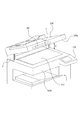
次に図7及び図8を用いて本発明に係る画像形成装置の第1実施形態の構成について説明する。尚、前記第1実施形態と同様に構成したものは同一の符号を付して説明を省略する。   Next, the configuration of the first embodiment of the image forming apparatus according to the present invention will be described with reference to FIGS. In addition, what was comprised similarly to the said 1st Embodiment attaches | subjects the same code | symbol, and abbreviate | omits description.

前記第1実施形態では、図3〜図5に示したように、ベース3に設けられた長穴3aが上下方向に形成され、ADF200に固定されるADF回動支点24が該長穴3aに沿って図3〜図5の上下方向に移動する構成とした。   In the first embodiment, as shown in FIGS. 3 to 5, the long hole 3 a provided in the base 3 is formed in the vertical direction, and the ADF rotation fulcrum 24 fixed to the ADF 200 is formed in the long hole 3 a. It was set as the structure which moves to the up-down direction of FIGS.

本実施形態では、図7及び図8に示すように、ベース3に設けられた長穴3aの上方が画像形成装置本体100の前方側に傾斜して形成される。そして、ADF200に固定されるADF回動支点24が傾斜した該長穴3aに沿って図7及び図8の左下から右上方向に移動する構成とした。   In the present embodiment, as shown in FIGS. 7 and 8, the upper portion of the elongated hole 3 a provided in the base 3 is formed to be inclined toward the front side of the image forming apparatus main body 100. The ADF rotation fulcrum 24 fixed to the ADF 200 moves from the lower left to the upper right in FIGS. 7 and 8 along the inclined long hole 3a.

本実施形態でも、前記第1実施形態と同様に、図7及び図8に示すように、画像形成装置本体100の上面に読取原稿をセットする原稿台111が設けられる。原稿台111の上面にはセットされた複数の原稿を自動的に1枚づつ順次、原稿台111に搬送するADF200が原稿押圧部保持手段となるリンク機構7により画像形成装置本体100に対して開閉可能に設置されている。   Also in the present embodiment, as in the first embodiment, as shown in FIGS. 7 and 8, a document table 111 for setting a read document on the upper surface of the image forming apparatus main body 100 is provided. On the upper surface of the document table 111, the ADF 200 that automatically and sequentially feeds a plurality of documents set one by one to the document table 111 is opened and closed with respect to the image forming apparatus main body 100 by the link mechanism 7 serving as a document pressing unit holding means. It is installed as possible.

画像形成装置本体100の後側上部にL字形状のベース3が固定されている。ベース3には図7及び図8の左下から右上方向に傾斜した長穴3aが形成されている。ベース3にはアーム回動支点21を中心に回動可能に取り付けられたアーム1が設けられている。アーム1にはリンク回動支点22を中心に回動可能に取り付けられたリンク2が設けられている。   An L-shaped base 3 is fixed to the rear upper part of the image forming apparatus main body 100. A long hole 3a is formed in the base 3 so as to be inclined from the lower left to the upper right in FIGS. The base 3 is provided with an arm 1 attached so as to be rotatable about an arm rotation fulcrum 21. The arm 1 is provided with a link 2 attached so as to be rotatable about a link rotation fulcrum 22.

リンク2の一端部にはアーム1に形成された長穴3aに沿って移動し得るADF回動支点24を中心に回動可能に支持されたADF200が設けられている。また、ADF200は、アーム1に形成された長穴1aに沿って移動し得るスライダ支点23により支持されている。ADF200は、その下面に原稿押圧部200aを有する。   One end of the link 2 is provided with an ADF 200 supported so as to be rotatable about an ADF rotation fulcrum 24 that can move along an elongated hole 3 a formed in the arm 1. The ADF 200 is supported by a slider fulcrum 23 that can move along the long hole 1 a formed in the arm 1. The ADF 200 has a document pressing portion 200a on its lower surface.

アーム1の先端には圧縮バネ4が固定されており該圧縮バネ4の他端は、前記第1実施形態と同様に、調整ネジ6と調整ダイアル5を介してADF200に固定されている。調整ダイアル5の内周面には調整ネジ6と螺合する図示しない雌ネジ部が形成されており、調整ダイアル5を回転させることで調整ネジ6が該調整ダイアル5の回転方向により図7の右方向または左方向に移動する。これにより、圧縮バネ4がアーム1に加える押圧力の調整を可能にしている。尚、図7及び図8は画像形成装置本体100の左側面側に設けられたリンク機構7の構成を示したものであるが、画像形成装置本体100の右側面側にも対称的に構成されるリンク機構7が設置されている。   A compression spring 4 is fixed to the tip of the arm 1, and the other end of the compression spring 4 is fixed to the ADF 200 via the adjustment screw 6 and the adjustment dial 5 as in the first embodiment. A female screw portion (not shown) that is screwed with the adjustment screw 6 is formed on the inner peripheral surface of the adjustment dial 5. By rotating the adjustment dial 5, the adjustment screw 6 changes depending on the rotation direction of the adjustment dial 5 as shown in FIG. Move right or left. Thereby, adjustment of the pressing force which the compression spring 4 applies to the arm 1 is enabled. 7 and 8 show the configuration of the link mechanism 7 provided on the left side of the image forming apparatus main body 100, but it is also configured symmetrically on the right side of the image forming apparatus main body 100. FIG. A link mechanism 7 is installed.

ここで、ユーザが図8に示すようにADF200を開いて図示しない原稿を原稿台111にセットする場合、ADF200に設けられたハンドル201に開く力F1を加えて持ち上げる。これにより、図8に示すように、アーム回動支点21を中心にアーム1が図8の反時計回り方向に回動する。   Here, when the user opens the ADF 200 as shown in FIG. 8 and sets a document (not shown) on the document table 111, the user lifts the handle 201 provided on the ADF 200 by applying an opening force F1. As a result, as shown in FIG. 8, the arm 1 rotates in the counterclockwise direction of FIG. 8 around the arm rotation fulcrum 21.

アーム1の回動により、リンク2がリンク回動支点22を中心に回動しつつ該リンク2の一端部に設けられたADF回動支点24がベース3に形成された長穴3aに沿ってADF200と共に図8の右上方向に押し上げられて移動する。また、スライダ支点23はアーム1の長穴1aに沿って図8の右方向に移動する。その結果、リンク2とADF回動支点24を介して固定されているADF200は図8に示すように、右斜め上方に押し上げられながら開く。   As the arm 1 rotates, the link 2 rotates about the link rotation fulcrum 22 and the ADF rotation fulcrum 24 provided at one end of the link 2 extends along the elongated hole 3 a formed in the base 3. Together with the ADF 200, it is pushed up and moved in the upper right direction in FIG. Further, the slider fulcrum 23 moves in the right direction in FIG. 8 along the long hole 1 a of the arm 1. As a result, the ADF 200 fixed via the link 2 and the ADF rotation fulcrum 24 is opened while being pushed upward to the right as shown in FIG.

本実施形態では、原稿押圧部保持手段となるリンク機構7により、原稿押圧部200aを有するADF200を画像形成装置本体100に対して開閉可能に支持する。ADF200を画像形成装置本体100に対して開閉可能に支持するADF回動支点24が該ADF200の開放動作に連動して原稿台111を基準として、上方で且つ該ADF200の開放側となる図8の右上方向に押し上げられて移動する。   In the present embodiment, the ADF 200 having the document pressing portion 200a is supported to the image forming apparatus main body 100 so as to be opened and closed by the link mechanism 7 serving as a document pressing portion holding means. The ADF rotation fulcrum 24 that supports the ADF 200 with respect to the image forming apparatus main body 100 so as to be openable and closable is above and on the open side of the ADF 200 in FIG. Moves when pushed up in the upper right direction.

このとき、図8に示すように、予め圧縮された状態の圧縮バネ4はアーム1に押圧力を加えつつ解放される。その結果、圧縮バネ4の押圧力がADF200の開放に必要な開く力F1を軽減する方向に作用する。   At this time, as shown in FIG. 8, the compression spring 4 in a previously compressed state is released while applying a pressing force to the arm 1. As a result, the pressing force of the compression spring 4 acts in the direction of reducing the opening force F1 necessary for opening the ADF 200.

ADF200の自重は、ADF回動支点24を介してリンク2と、長穴1aにスライド自在に係合されたスライダ支点23を介してアーム1とを介して常にADF200を閉じる方向に作用している。   The weight of the ADF 200 always acts in the direction of closing the ADF 200 via the link 2 via the ADF rotation fulcrum 24 and the arm 1 via the slider fulcrum 23 slidably engaged with the elongated hole 1a. .

一方、圧縮バネ4の押圧力は、アーム1を図7の左方向に加圧し、これにより、アーム1上に設けられた長穴1aと係合するスライダ支点23が該長穴1aに沿って図7の右方向に移動するように作用するため、常時、ADF200を開く方向に作用している。このため、図8において、ユーザがADF200を開く力F1及びADF200を閉じる力F2を共に加えない状態でも、ADF200の自重と圧縮バネ4の押圧力とを拮抗させることで、所定の開放角度でADF200の位置を停止させることが可能となる。   On the other hand, the pressing force of the compression spring 4 pressurizes the arm 1 in the left direction of FIG. 7, so that the slider fulcrum 23 engaged with the elongated hole 1 a provided on the arm 1 extends along the elongated hole 1 a. Since it acts so as to move to the right in FIG. 7, it always acts in the direction of opening the ADF 200. For this reason, in FIG. 8, even when the user does not apply both the force F1 for opening the ADF 200 and the force F2 for closing the ADF 200, the ADF 200 has a predetermined opening angle by antagonizing the weight of the ADF 200 and the pressing force of the compression spring 4. It becomes possible to stop the position.

圧縮バネ4は圧縮されることにより押圧力が増す。このため、該圧縮バネ4の押圧力とバネ長との関係から予めそれぞれのADF200の開放角度において該ADF200の自重と該圧縮バネ4の押圧力とがバランスした設定とする。これにより、ADF200を自由な開放角度で停止させることが出来る。   The compression spring 4 is compressed to increase the pressing force. For this reason, from the relationship between the pressing force of the compression spring 4 and the spring length, the weight of the ADF 200 and the pressing force of the compression spring 4 are balanced in advance at the opening angle of each ADF 200. Thereby, the ADF 200 can be stopped at a free opening angle.

また、前記第1実施形態と同様に調整ダイアル5を回転させることで調整ネジ6の位置が移動し、その結果、圧縮バネ4の押圧力の調整が可能な構成としている。このため、圧縮バネ4の押圧力の微調整によりADF200の停止可能な開放角度を調整することが出来る。   Further, the position of the adjustment screw 6 is moved by rotating the adjustment dial 5 as in the first embodiment, and as a result, the pressing force of the compression spring 4 can be adjusted. For this reason, the opening angle at which the ADF 200 can be stopped can be adjusted by fine adjustment of the pressing force of the compression spring 4.

上記構成により、原稿押圧部200aを有するADF200の画像形成装置本体100の後部側が上方で且つ画像形成装置本体100の手前側に移動する。このように画像形成装置本体100の後部側が上方向成分を持つ方向に移動することで第1実施形態と同様の効果を得ることができる。また、これにより、ADF200の開放角度が大きくなるにつれてハンドル201も画像形成装置本体100の手前側に移動する。このため、より背の低いユーザや車椅子を利用するユーザ等が自分の手の届く範囲内でハンドル201を操作することが出来るようになる。他の構成は、前記第1実施形態と同様に構成され、同様の効果を得ることが出来る。   With the above configuration, the rear side of the image forming apparatus main body 100 of the ADF 200 having the document pressing portion 200 a moves upward and to the front side of the image forming apparatus main body 100. Thus, the same effect as that of the first embodiment can be obtained by moving the rear side of the image forming apparatus main body 100 in the direction having the upward component. As a result, the handle 201 also moves to the near side of the image forming apparatus main body 100 as the opening angle of the ADF 200 increases. Therefore, a shorter user, a user using a wheelchair, and the like can operate the handle 201 within the reach of his / her hand. Other configurations are the same as those in the first embodiment, and the same effects can be obtained.

次に図9及び図10を用いて本発明に係る画像形成装置の第3実施形態の構成について説明する。尚、前記各実施形態と同様に構成したものは、同一の符号を付して説明を省略する。   Next, the configuration of the third embodiment of the image forming apparatus according to the present invention will be described with reference to FIGS. In addition, what was comprised similarly to the said each embodiment attaches | subjects the same code | symbol, and abbreviate | omits description.

前記各実施形態では、アーム1に設けられた長穴1aに対してADF200に固定されたスライダ支点23がスライド自在に構成した。本実施形態では、アーム1に設けられた長穴1aの略全長に亘ってラック1bが設けられ、スライダ支点23の軸部材に前記ラック1bに噛合して回転移動するピニオンギア13が設けられている。   In each of the above embodiments, the slider fulcrum 23 fixed to the ADF 200 is configured to be slidable with respect to the long hole 1a provided in the arm 1. In the present embodiment, the rack 1b is provided over substantially the entire length of the long hole 1a provided in the arm 1, and the pinion gear 13 that meshes with the rack 1b and rotates and moves on the shaft member of the slider fulcrum 23 is provided. Yes.

ピニオンギア13と同軸上には、一方向ロータリーダンパ14が設けられている。一方向ロータリーダンパ14は原稿押圧部200aを有するADF200の閉動作時に負荷を与える減衰手段である。また、一方向ロータリーダンパ14はADF200の閉動作時にのみ所定の負荷が作用し、該ADF200の開動作時には何ら負荷が作用しない一方向減衰手段である。   A one-way rotary damper 14 is provided coaxially with the pinion gear 13. The one-way rotary damper 14 is a damping unit that applies a load when the ADF 200 having the document pressing portion 200a is closed. The one-way rotary damper 14 is a one-way damping means in which a predetermined load acts only when the ADF 200 is closed, and no load acts when the ADF 200 is opened.

図9及び図10において、前記第1実施形態と同様に画像形成装置本体100の上面には読取原稿をセットする原稿台111が設けられている。原稿台111の上面にはセットされた複数の原稿を自動的に1枚づつ順次、原稿台111に搬送するADF200が画像形成装置本体100に対して開放可能に設置されている。   9 and 10, a document table 111 for setting a read document is provided on the upper surface of the image forming apparatus main body 100 as in the first embodiment. On the upper surface of the document table 111, an ADF 200 that automatically and sequentially feeds a plurality of set documents one by one to the document table 111 is installed so as to be openable to the image forming apparatus main body 100.

画像形成装置本体100の後方上部側面にL字形状のベース3が固定されている。ベース3にはアーム回動支点21を中心に回動可能なアーム1が設けられている。アーム1にはリンク回動支点22を中心に回動可能なリンク2が設けられている。リンク2の一端部に設けられたADF回動支点24はベース3に形成された長穴3aに沿って移動可能に設けられ、ADF200の側面に固定されている。   An L-shaped base 3 is fixed to the rear upper side surface of the image forming apparatus main body 100. The base 3 is provided with an arm 1 that can rotate around an arm rotation fulcrum 21. The arm 1 is provided with a link 2 that can rotate around a link rotation fulcrum 22. An ADF rotation fulcrum 24 provided at one end of the link 2 is provided so as to be movable along a long hole 3 a formed in the base 3, and is fixed to a side surface of the ADF 200.

アーム1に形成された長穴1aにはラック1bが形成されており、該ラック1bにはピニオンギア13が噛合されている。ピニオンギア13と同軸上に設けられた一方向ロータリーダンパ14は、図10に示す矢印D方向(図10の反時計回り方向)にピニオンギア13が回転する場合には何ら負荷なく自由に回転させる。また、ピニオンギア13が図10に示す矢印E方向(図10の時計回り方向)に回転しようとする場合には、所定の負荷を与える。ピニオンギア13はADF200の側面に回転可能に固定されている。   A rack 1b is formed in the elongated hole 1a formed in the arm 1, and a pinion gear 13 is engaged with the rack 1b. The one-way rotary damper 14 provided coaxially with the pinion gear 13 is freely rotated without any load when the pinion gear 13 rotates in the direction of arrow D shown in FIG. 10 (counterclockwise direction in FIG. 10). . Further, when the pinion gear 13 tries to rotate in the direction of arrow E shown in FIG. 10 (clockwise direction in FIG. 10), a predetermined load is applied. The pinion gear 13 is rotatably fixed to the side surface of the ADF 200.

ここで、図9に示すように、ユーザがADF200を開いて図示しない原稿を原稿台111にセットする場合、ADF200に設けられたハンドル201に開く力F1を加えて持ち上げる。これにより、図9に示すように、アーム回動支点21を中心にアーム1が図9の反時計回り方向に回転する。アーム1の回転によりリンク2がリンク回動支点22を中心に回動しつつADF回動支点24がベース3に設けた長穴3aに沿ってADF200と共に上方に押し上げられて移動する。また、スライダ支点23に設けられたピニオンギア13はアーム1の長穴1aに設けられたラック1bに噛合しつつ図10の矢印D方向に何ら負荷なく回転しつつ図9の右方向に移動する。   Here, as shown in FIG. 9, when the user opens the ADF 200 and sets a document (not shown) on the document table 111, the user lifts the handle 201 provided on the ADF 200 by applying an opening force F <b> 1. As a result, as shown in FIG. 9, the arm 1 rotates in the counterclockwise direction of FIG. 9 around the arm rotation fulcrum 21. As the arm 1 rotates, the link 2 rotates around the link rotation fulcrum 22 and the ADF rotation fulcrum 24 is pushed upward together with the ADF 200 along the elongated hole 3 a provided in the base 3. Further, the pinion gear 13 provided at the slider fulcrum 23 moves in the right direction in FIG. 9 while rotating in the direction of arrow D in FIG. 10 without any load while meshing with the rack 1b provided in the elongated hole 1a of the arm 1. .

その結果、リンク2とADF回動支点24を介して固定されているADF200は、図9及び図10に示すように、上方に押し上げられながら開く。このとき、予め圧縮された状態の圧縮バネ4はアーム1に押圧力を加えつつ解放される。その結果、圧縮バネ4の押圧力がADF200を開放するのに必要な開く力F1を軽減する方向に作用する。   As a result, the ADF 200 fixed via the link 2 and the ADF rotation fulcrum 24 is opened while being pushed upward as shown in FIGS. At this time, the precompressed compression spring 4 is released while applying a pressing force to the arm 1. As a result, the pressing force of the compression spring 4 acts in the direction of reducing the opening force F1 necessary for opening the ADF 200.

ADF200の自重は、ADF回動支点24を介して回転自在に連結されたリンク2と、スライダ支点23に設けられたピニオンギア13とラック1bとが噛合して係合されたアーム1とを介して常にADF200を閉じる方向に作用している。   The weight of the ADF 200 is via the link 2 rotatably connected via the ADF rotation fulcrum 24, and the arm 1 engaged with the rack 1b engaged with the pinion gear 13 provided on the slider fulcrum 23. Always acting in the direction of closing the ADF 200.

一方、圧縮バネ4の押圧力は、アーム1を図9の左方向に押圧する。これにより、アーム1上に設けられた長穴1aに設けられたラック1bと噛合するピニオンギア13が該ラック1bに沿って図9の右方向に移動するように作用する。このため、常時、ADF200を開く方向に作用している。   On the other hand, the pressing force of the compression spring 4 presses the arm 1 leftward in FIG. As a result, the pinion gear 13 that meshes with the rack 1b provided in the elongated hole 1a provided on the arm 1 acts so as to move to the right in FIG. 9 along the rack 1b. For this reason, it always acts in the direction in which the ADF 200 is opened.

また、一方向ロータリーダンパ14は、ピニオンギア13が図10に示す矢印E方向(図10の時計回り方向)に回転する場合に所定の負荷を与える。また、ピニオンギア13が図10に示す矢印D方向(図10の反時計回り方向)に回転する場合は何ら負荷を与えない。このためピニオンギア13は自由に回転する。   The one-way rotary damper 14 applies a predetermined load when the pinion gear 13 rotates in the direction of arrow E shown in FIG. 10 (the clockwise direction in FIG. 10). Further, when the pinion gear 13 rotates in the direction of arrow D shown in FIG. 10 (counterclockwise direction in FIG. 10), no load is applied. For this reason, the pinion gear 13 rotates freely.

ADF200を閉じる方向では、ピニオンギア13がアーム1の長穴1aに設けられたラック1bに噛合しつつ該ラック1bに沿って図9の左方向に移動するように図10の矢印E方向(図10の時計回り方向)に回転しようとする。このため、一方向ロータリーダンパ14は該ピニオンギア13の回転に所定の負荷を与える。   In the direction to close the ADF 200, the pinion gear 13 engages with the rack 1b provided in the elongated hole 1a of the arm 1 and moves to the left in FIG. Try to rotate 10 clockwise). For this reason, the one-way rotary damper 14 applies a predetermined load to the rotation of the pinion gear 13.

このため、図9において、ユーザがADF200を開く力F1及びADF200を閉じる力F2を共に加えない状態でも、一方向ロータリーダンパ14による負荷と、圧縮バネ4の押圧力との合成力を、ADF200の自重に対して拮抗させる。これにより、所定の開放角度でADF200の位置を停止させることが可能となる。   For this reason, in FIG. 9, even when the user does not apply both the force F1 for opening the ADF 200 and the force F2 for closing the ADF 200, the combined force of the load by the one-way rotary damper 14 and the pressing force of the compression spring 4 is Antagonize against self-weight. As a result, the position of the ADF 200 can be stopped at a predetermined opening angle.

例えば、ADF200の停止可能な範囲を図10に示す位置Aから位置Cまでの開放角度の範囲に設定する。この範囲でADF200は外力が加わらなければ停止した状態を維持する。これにより、小柄なユーザや車椅子を利用するユーザが原稿台111上での原稿のセット等を行うに際して、ADF200の開放角度を自由な角度で操作することが可能である。   For example, the range where the ADF 200 can be stopped is set to the range of the opening angle from the position A to the position C shown in FIG. Within this range, the ADF 200 maintains a stopped state unless an external force is applied. Thereby, when a small user or a user using a wheelchair sets a document on the platen 111, the opening angle of the ADF 200 can be operated at a free angle.

一方、図10に示す位置Bから位置Aまでの開放角度の範囲は、ADF200の自重が、一方向ロータリーダンパ14の負荷と圧縮バネ4の押圧力との合成力よりも僅かに勝る設定をする。これにより、ADF200が所定の時間をかけてゆっくりと位置Aまで降下して停止する構成としている。   On the other hand, the range of the opening angle from the position B to the position A shown in FIG. 10 is set so that the weight of the ADF 200 slightly exceeds the combined force of the load of the one-way rotary damper 14 and the pressing force of the compression spring 4. . Thus, the ADF 200 is slowly lowered to the position A over a predetermined time and stopped.

原稿押圧部保持手段となるリンク機構7は、原稿押圧部200aを有するADF200の開閉可能範囲となる図10に示す位置Bから位置Cの範囲内(開閉可能範囲内)に原稿押圧部200aを有するADF200の中間停止位置となる位置Aを有する。   The link mechanism 7 serving as the document pressing portion holding means has the document pressing portion 200a within a range (position within the opening / closing range) from the position B to the position C shown in FIG. 10 which is an openable / closable range of the ADF 200 having the document pressing portion 200a. The position A is an intermediate stop position of the ADF 200.

位置Bは原稿押圧部200aを有するADF200の全開状態である。位置Bから中間停止位置となる位置Aまでの範囲にあるADF200は、外部からの付勢力が無い限り位置Aまで徐々に降下して該位置Aで停止する。   The position B is a fully opened state of the ADF 200 having the document pressing portion 200a. The ADF 200 in the range from the position B to the position A that is the intermediate stop position gradually descends to the position A and stops at the position A unless there is an external biasing force.

これにより、一般的なユーザがADF200を図10に示す位置Bまで開いて使用する場合、ユーザが原稿台111上に原稿をセットするときにADF200から手を離した状態でも該ADF200がゆっくりとした降下をすることで、操作に影響が無い。仮に、ADF200を位置Bまで開放したまま放置された場合でも該ADF200が徐々に位置Aまで降下して停止する。これにより、次に使用する小柄なユーザや車椅子を利用するユーザがADF200のハンドル201に手が届かない等の不便を解消する。   Thus, when a general user opens and uses the ADF 200 to the position B shown in FIG. 10, the ADF 200 becomes slow even when the user releases his hand from the ADF 200 when setting the document on the document table 111. There is no effect on the operation by descending. Even if the ADF 200 is left open to the position B, the ADF 200 gradually descends to the position A and stops. This eliminates the inconvenience such as a small user to be used next and a user using a wheelchair cannot reach the handle 201 of the ADF 200.

また、圧縮バネ4は圧縮されることにより押圧力が増すため、圧縮バネ4の押圧力とバネ長との関係から予めADF200のそれぞれの開放角度において該ADF200の自重とバランスした設定とする。これにより、ADF200の開放角度を自由な角度で停止が可能な構成としている。   In addition, since the compression spring 4 is compressed to increase the pressing force, it is set in advance so as to be balanced with the weight of the ADF 200 at each opening angle of the ADF 200 from the relationship between the pressing force of the compression spring 4 and the spring length. Thereby, the opening angle of the ADF 200 can be stopped at any angle.

更に、調整ダイアル5を回転させることで調整ネジ6の位置が移動し、その結果、圧縮バネ4の押圧力の調整が可能な構成としている。このため、圧縮バネ4の押圧力の微調整によりADF200が停止可能な開放角度を調整することが出来る。   Furthermore, the position of the adjustment screw 6 is moved by rotating the adjustment dial 5, and as a result, the pressing force of the compression spring 4 can be adjusted. Therefore, the opening angle at which the ADF 200 can be stopped can be adjusted by fine adjustment of the pressing force of the compression spring 4.

尚、図9及び図10においては、画像形成装置本体100の左側面側にリンク機構7を設けた構成について説明したが、前記各実施形態と同様に画像形成装置本体100の右側面側にも対称的なリンク機構7が設けられている。   9 and 10, the configuration in which the link mechanism 7 is provided on the left side surface of the image forming apparatus main body 100 has been described. A symmetrical link mechanism 7 is provided.

また、ピニオンギア13に一方向ロータリーダンパ14を設けてピニオンギア13の一方向の回転に負荷を与えると共に、圧縮バネ4の押圧力と組み合わせることで、ADF200を任意の角度まで緩やかに降下させ、任意の角度で停止させる構成とした。更に圧縮バネ4の押圧力を調整可能とする構成としたことでADF200の停止角度の調整を可能にしている。   In addition, a one-way rotary damper 14 is provided on the pinion gear 13 to apply a load to the rotation of the pinion gear 13 in one direction, and in combination with the pressing force of the compression spring 4, the ADF 200 is gently lowered to an arbitrary angle, It was set as the structure which stops at arbitrary angles. Further, since the pressing force of the compression spring 4 can be adjusted, the stop angle of the ADF 200 can be adjusted.

また、ピニオンギア13の一方向の回転に負荷を与える一方向ロータリーダンパ14を設けたことで、一般のユーザがADF200を全開にして使用する。このときは、一方向ロータリーダンパ14の作用によりADF200をしばらくは全開状態に近い状態のまま保持することが出来る。   Further, by providing the one-way rotary damper 14 for applying a load to the one-way rotation of the pinion gear 13, a general user uses the ADF 200 with the ADF 200 fully opened. At this time, the ADF 200 can be held in a state close to the fully open state for a while by the action of the one-way rotary damper 14.

その後、仮にADF200が全開状態で放置された場合でも、一方向ロータリーダンパ14の作用により徐々に所定の開放角度までADF200を降下させることが出来る。これにより、背の低いユーザや車椅子を利用するユーザがADF200のハンドル201に手が届かないといったトラブルを未然に防止することが出来る。他の構成は前記各実施形態と同様に構成され、同様の効果を得ることが出来る。   Thereafter, even if the ADF 200 is left in a fully opened state, the ADF 200 can be gradually lowered to a predetermined opening angle by the action of the one-way rotary damper 14. As a result, it is possible to prevent trouble that a short user or a user using a wheelchair cannot reach the handle 201 of the ADF 200. Other configurations are the same as those in the above embodiments, and the same effects can be obtained.

次に図11及び図12を用いて本発明に係る画像形成装置の第4実施形態の構成について説明する。尚、前記各実施形態と同様に構成したものは、同一の符号を付して説明を省略する。   Next, the configuration of the fourth embodiment of the image forming apparatus according to the present invention will be described with reference to FIGS. In addition, what was comprised similarly to the said each embodiment attaches | subjects the same code | symbol, and abbreviate | omits description.

本実施形態では、原稿押圧部保持手段となるリンク機構7を図12に示すようにユニット化して左側リンクユニット8及び右側リンクユニット9を作成する。そして、該左側リンクユニット8及び右側リンクユニット9を原稿押圧部200aを有するADF200の左右側面と、画像形成装置本体100の左右側面に対して着脱可能に構成したものである。   In the present embodiment, the link mechanism 7 serving as the document pressing portion holding unit is unitized as shown in FIG. 12 to create the left link unit 8 and the right link unit 9. The left link unit 8 and the right link unit 9 are configured to be detachable from the left and right side surfaces of the ADF 200 having the document pressing portion 200a and the left and right side surfaces of the image forming apparatus main body 100.

図11において、前記各実施形態と同様に、画像形成装置本体100の上面には読取原稿を自動的に1枚づつ順次、原稿台111に搬送するADF200が開放可能に設置されている。   In FIG. 11, similarly to the above-described embodiments, an ADF 200 that automatically and sequentially feeds read documents one by one to the document table 111 is installed on the upper surface of the image forming apparatus main body 100 so as to be openable.

前記各実施形態と同様のリンク機構7を内蔵してユニット化した左側リンクユニット8及び右側リンクユニット9を作成する。そして、図12に示すビス30により該左側リンクユニット8及び右側リンクユニット9を画像形成装置本体100の後方上部の左右側面及びADF200の左右側面に設けられたビス孔31に締結して着脱可能に構成されている。   The left link unit 8 and the right link unit 9 which are unitized by incorporating the link mechanism 7 similar to that of each of the embodiments described above are created. Then, the left link unit 8 and the right link unit 9 are fastened to screw holes 31 provided on the left and right side surfaces of the rear upper portion of the image forming apparatus main body 100 and the left and right side surfaces of the ADF 200 by screws 30 shown in FIG. It is configured.

尚、図12は第1実施形態のリンク機構7を内蔵してユニット化した左側リンクユニット8の一例を示す。尚、右側リンクユニット9は左側リンクユニット8と対称的なリンク機構7を内蔵してユニット化する。他に、前述した他の各実施形態のリンク機構7を内蔵してユニット化した左側リンクユニット8及び右側リンクユニット9とすることも出来る。   FIG. 12 shows an example of the left link unit 8 which is unitized by incorporating the link mechanism 7 of the first embodiment. Note that the right link unit 9 incorporates a link mechanism 7 symmetrical to the left link unit 8 and is unitized. In addition, the left link unit 8 and the right link unit 9 which are unitized by incorporating the link mechanisms 7 of the other embodiments described above may be used.

画像形成装置本体100の後方上部の左右側面及びADF200の左右側面には、左側リンクユニット8及び右側リンクユニット9をビス30により締結するためのビス孔31が設けられている。従来例のヒンジ部材を用いてADF200を画像形成装置本体100に対して開閉可能に構成した状態で使用する場合は、それらのビス孔31は、カバー10,11,12,15によってそれぞれ覆われている。   Screw holes 31 for fastening the left link unit 8 and the right link unit 9 with screws 30 are provided on the left and right side surfaces of the upper rear portion of the image forming apparatus main body 100 and the left and right side surfaces of the ADF 200. When the ADF 200 is configured to be openable and closable with respect to the image forming apparatus main body 100 using the hinge member of the conventional example, the screw holes 31 are respectively covered by the covers 10, 11, 12, and 15. Yes.

そして、リンク機構7をユニット化した左側リンクユニット8及び右側リンクユニット9を画像形成装置本体100の後方上部の左右側面及びADF200の左右側面に装着して使用する。その場合は、従来例の図示しないヒンジ部材を画像形成装置本体100及びADF200から取り外す。   The left link unit 8 and the right link unit 9 obtained by unitizing the link mechanism 7 are attached to the left and right side surfaces of the rear upper part of the image forming apparatus main body 100 and the left and right side surfaces of the ADF 200 for use. In that case, the hinge member (not shown) of the conventional example is removed from the image forming apparatus main body 100 and the ADF 200.

更に、カバー10,11,12,15を取り外して左側リンクユニット8及び右側リンクユニット9を装着するためのビス30用のビス孔31を露出させる。そして、左側リンクユニット8及び右側リンクユニット9をビス30により画像形成装置本体100の後方上部の左右側面及びADF200の左右側面にそれぞれ設けられたビス孔31に取り付ける。   Further, the covers 10, 11, 12, 15 are removed to expose the screw holes 31 for the screws 30 for mounting the left link unit 8 and the right link unit 9. Then, the left link unit 8 and the right link unit 9 are attached to the screw holes 31 respectively provided on the left and right side surfaces of the rear upper portion of the image forming apparatus main body 100 and the left and right side surfaces of the ADF 200 with screws 30.

これにより、従来例のヒンジ部材と、リンク機構7をユニット化した左側リンクユニット8及び右側リンクユニット9とを簡単に変更可能な構成としている。他の構成は前記各実施形態と同様に構成され、同様の効果を得ることが出来る。   Thereby, it is set as the structure which can change easily the hinge member of a prior art example, and the left side link unit 8 and the right side link unit 9 which unitized the link mechanism 7. FIG. Other configurations are the same as those in the above embodiments, and the same effects can be obtained.

7 …リンク機構(原稿押圧部保持手段)
24 …ADF回動支点
100 …画像形成装置本体
100a …原稿読取装置本体
111 …原稿台
200 …ADF
200a …原稿押圧部
7. Link mechanism (document pressing part holding means)
24… ADF rotation fulcrum
100 ... Image forming apparatus main body
100a ... Document reading device main body
111… manuscript table
200 ... ADF
200a: Document pressing part

Claims (9)

原稿読取装置本体に対して開閉可能に構成され、原稿台に載置された原稿を押圧する原稿押圧部を備えた原稿読取装置を有する画像形成装置において、
前記原稿押圧部を開閉可能に支持する支点が、該原稿押圧部の開放動作に連動して前記原稿台を基準として、上方に移動する原稿押圧部保持手段を有することを特徴とする画像形成装置。
In an image forming apparatus having a document reading device that is configured to be openable and closable with respect to a document reading device main body and includes a document pressing unit that presses a document placed on a document table.
An image forming apparatus characterized in that a fulcrum that supports the document pressing portion so as to be openable / closable has document pressing portion holding means that moves upward with respect to the document table in conjunction with an opening operation of the document pressing portion. .
原稿読取装置本体に対して開閉可能に構成され、原稿台に載置された原稿を押圧する原稿押圧部を備えた原稿読取装置を有する画像形成装置において、
前記原稿押圧部を開閉可能に支持する支点が、該原稿押圧部の開放動作に連動して前記原稿台を基準として、上方で且つ前記原稿押圧部の開放側に移動する原稿押圧部保持手段を有することを特徴とする画像形成装置。
In an image forming apparatus having a document reading device that is configured to be openable and closable with respect to a document reading device main body and includes a document pressing unit that presses a document placed on a document table.
Document supporting portion holding means for supporting the document pressing portion so that the document pressing portion can be opened and closed is moved upward and to the opening side of the document pressing portion with respect to the document table in conjunction with the opening operation of the document pressing portion. An image forming apparatus comprising:
前記原稿押圧部保持手段は、前記原稿押圧部の開閉動作に連動するリンク機構を有し、
前記リンク機構は、前記原稿押圧部の自重に拮抗する付勢部材を有することを特徴とする請求項1または請求項2に記載の画像形成装置。
The document pressing portion holding means has a link mechanism that interlocks with the opening / closing operation of the document pressing portion,
The image forming apparatus according to claim 1, wherein the link mechanism includes a biasing member that antagonizes the weight of the document pressing unit.
前記付勢部材の押圧力を調整する押圧力調整手段を有することを特徴とする請求項3に記載の画像形成装置。 The image forming apparatus according to claim 3, further comprising a pressing force adjusting unit that adjusts a pressing force of the urging member. 前記原稿押圧部は、複数の原稿を自動搬送する自動原稿搬送装置を有することを特徴とする請求項1〜4のいずれか1項に記載の画像形成装置。 The image forming apparatus according to claim 1, wherein the document pressing unit includes an automatic document transport device that automatically transports a plurality of documents. 前記原稿押圧部の閉動作時に負荷を与える減衰手段を有することを特徴とする請求項1〜5のいずれか1項に記載の画像形成装置。 The image forming apparatus according to claim 1, further comprising an attenuating unit that applies a load when the original pressing unit is closed. 前記減衰手段は、前記原稿押圧部の閉動作時にのみ負荷が作用する一方向減衰手段であることを特徴とする請求項6に記載の画像形成装置。 The image forming apparatus according to claim 6, wherein the attenuating unit is a one-way attenuating unit that applies a load only when the original pressing unit is closed. 前記原稿押圧部保持手段は、前記原稿押圧部および前記原稿読取装置に対して着脱可能に設けられたことを特徴とする請求項1〜7のいずれか1項に記載の画像形成装置。 The image forming apparatus according to claim 1, wherein the document pressing unit holding unit is detachably attached to the document pressing unit and the document reading device. 前記原稿押圧部保持手段は、前記原稿押圧部の開閉可能範囲内に該原稿押圧部の中間停止位置を有し、前記原稿押圧部の全開状態から前記中間停止位置までの範囲にある該原稿押圧部は、外部からの付勢力が無い限り前記中間停止位置まで徐々に降下して該中間停止位置で停止することを特徴とする請求項1〜8のいずれか1項に記載の画像形成装置。 The document pressing portion holding means has an intermediate stop position of the document pressing portion within an openable / closable range of the document pressing portion, and the document pressing portion is in a range from the fully open state of the document pressing portion to the intermediate stop position. The image forming apparatus according to claim 1, wherein the unit gradually descends to the intermediate stop position and stops at the intermediate stop position unless there is an external biasing force.
JP2011191222A 2011-09-02 2011-09-02 Image forming device Pending JP2013055437A (en)

Priority Applications (1)

Application Number Priority Date Filing Date Title
JP2011191222A JP2013055437A (en) 2011-09-02 2011-09-02 Image forming device

Applications Claiming Priority (1)

Application Number Priority Date Filing Date Title
JP2011191222A JP2013055437A (en) 2011-09-02 2011-09-02 Image forming device

Related Child Applications (1)

Application Number Title Priority Date Filing Date
JP2016004421A Division JP6188835B2 (en) 2016-01-13 2016-01-13 Document reading apparatus and image forming apparatus

Publications (2)

Publication Number Publication Date
JP2013055437A true JP2013055437A (en) 2013-03-21
JP2013055437A5 JP2013055437A5 (en) 2014-10-16

Family

ID=48132077

Family Applications (1)

Application Number Title Priority Date Filing Date
JP2011191222A Pending JP2013055437A (en) 2011-09-02 2011-09-02 Image forming device

Country Status (1)

Country Link
JP (1) JP2013055437A (en)

Cited By (1)

* Cited by examiner, † Cited by third party
Publication number Priority date Publication date Assignee Title
JP2015115617A (en) * 2013-12-06 2015-06-22 ブラザー工業株式会社 Opening/closing device, and image recorder

Citations (4)

* Cited by examiner, † Cited by third party
Publication number Priority date Publication date Assignee Title
JPH11119354A (en) * 1997-10-16 1999-04-30 Murata Mach Ltd Original reader
JP2008268521A (en) * 2007-04-19 2008-11-06 Kato Electrical Mach Co Ltd Original pressing plate opening/closing device and office equipment equipped with original pressing plate
JP2009058790A (en) * 2007-08-31 2009-03-19 Kato Electrical Mach Co Ltd Original pressing plate opening/closing device and office equipment equipped with original pressing plate
JP2010139542A (en) * 2008-12-09 2010-06-24 Kato Electrical Mach Co Ltd Original cover plate opening/closing device and office equipment

Patent Citations (4)

* Cited by examiner, † Cited by third party
Publication number Priority date Publication date Assignee Title
JPH11119354A (en) * 1997-10-16 1999-04-30 Murata Mach Ltd Original reader
JP2008268521A (en) * 2007-04-19 2008-11-06 Kato Electrical Mach Co Ltd Original pressing plate opening/closing device and office equipment equipped with original pressing plate
JP2009058790A (en) * 2007-08-31 2009-03-19 Kato Electrical Mach Co Ltd Original pressing plate opening/closing device and office equipment equipped with original pressing plate
JP2010139542A (en) * 2008-12-09 2010-06-24 Kato Electrical Mach Co Ltd Original cover plate opening/closing device and office equipment

Cited By (1)

* Cited by examiner, † Cited by third party
Publication number Priority date Publication date Assignee Title
JP2015115617A (en) * 2013-12-06 2015-06-22 ブラザー工業株式会社 Opening/closing device, and image recorder

Similar Documents

Publication Publication Date Title
US10555603B2 (en) Height adjustable workstation
US6016171A (en) Height-adjustable case structure for the display of portable computers
US20070206349A1 (en) Adjustable display screen for a laptop computer
KR101570025B1 (en) Desk upper plate with free angle adjusting means
JP2017514323A (en) Hinge device for cover opening / closing of office equipment
JP2004101620A (en) Hinge device
TW200921257A (en) Apparatus for opening or closing plate pressing manuscript and office equipment with the same
EP3581723B1 (en) Slide-easy slide seat structure for portable and liftable rod
TW201318883A (en) Opening-closing device of copy pressing plate and office machine
JP2009232326A (en) Terminal apparatus
JP5653601B2 (en) Armrest device and chair equipped with the same
JP6188835B2 (en) Document reading apparatus and image forming apparatus
JP2017021244A (en) Lid body opening/closing device and various equipment comprising same lid body opening/closing device
JP2013055437A (en) Image forming device
TWI510047B (en) Handheld electronic device
JP5102085B2 (en) Folding lift table
JP6383932B2 (en) Standing assist device
KR101321014B1 (en) A portable tablet PC support
JPS5938734A (en) Opening and closing device of original pressing plate
JP4579090B2 (en) desk
KR20130027147A (en) The fixing device of tablet pc
KR101819106B1 (en) Height adjustment-Open type table
KR20220157274A (en) Structure for adjusting support force of lumbar pillow, and chair
JP2011142962A (en) Table storage mechanism for bed
JP2004229746A (en) Game machine frame

Legal Events

Date Code Title Description
A521 Written amendment

Free format text: JAPANESE INTERMEDIATE CODE: A523

Effective date: 20140901

A621 Written request for application examination

Free format text: JAPANESE INTERMEDIATE CODE: A621

Effective date: 20140901

A977 Report on retrieval

Free format text: JAPANESE INTERMEDIATE CODE: A971007

Effective date: 20150519

A131 Notification of reasons for refusal

Free format text: JAPANESE INTERMEDIATE CODE: A131

Effective date: 20150707

A521 Written amendment

Free format text: JAPANESE INTERMEDIATE CODE: A523

Effective date: 20150907

A02 Decision of refusal

Free format text: JAPANESE INTERMEDIATE CODE: A02

Effective date: 20151013