JP2013047525A - Turbocharger - Google Patents

Turbocharger Download PDF

Info

Publication number
JP2013047525A
JP2013047525A JP2012257474A JP2012257474A JP2013047525A JP 2013047525 A JP2013047525 A JP 2013047525A JP 2012257474 A JP2012257474 A JP 2012257474A JP 2012257474 A JP2012257474 A JP 2012257474A JP 2013047525 A JP2013047525 A JP 2013047525A
Authority
JP
Japan
Prior art keywords
heat shield
shield plate
housing
bearing housing
turbine
Prior art date
Legal status (The legal status is an assumption and is not a legal conclusion. Google has not performed a legal analysis and makes no representation as to the accuracy of the status listed.)
Pending
Application number
JP2012257474A
Other languages
Japanese (ja)
Other versions
JP2013047525A5 (en
Inventor
Norihiko Sumi
範彦 住
Current Assignee (The listed assignees may be inaccurate. Google has not performed a legal analysis and makes no representation or warranty as to the accuracy of the list.)
Toyota Motor Corp
Original Assignee
Toyota Motor Corp
Priority date (The priority date is an assumption and is not a legal conclusion. Google has not performed a legal analysis and makes no representation as to the accuracy of the date listed.)
Filing date
Publication date
Application filed by Toyota Motor Corp filed Critical Toyota Motor Corp
Priority to JP2012257474A priority Critical patent/JP2013047525A/en
Publication of JP2013047525A publication Critical patent/JP2013047525A/en
Publication of JP2013047525A5 publication Critical patent/JP2013047525A5/ja
Pending legal-status Critical Current

Links

Images

Abstract

PROBLEM TO BE SOLVED: To provide a turbocharger capable of securing sealing performance between a turbine housing and a bearing housing by a heat insulation board and preventing the corrosion of the bearing housing caused by the adhesion of condensation water.SOLUTION: A circular heat insulation board 50 interposed between the bearing housing 41 and the turbine housing 71 is formed over the entire circumferential direction of an outer end in a radiation direction of the heat insulation board 50, and the heat insulation board has a bent part 51a press-fitted in a bent state in a clearance part 104 formed over the entire circumferential direction of a flange 41a between a turbine housing side end face 41e of the flange 41a and a flange side inner peripheral face 71e of the turbine housing 71. By an elastic force of the bent part 51a, the heat insulation board is closely adhered to a face opposing the heat insulation board 50 of the turbine housing 71 or the bearing housing 41.

Description

本発明は、ターボチャージャに関し、特に、内燃機関から排出される排気ガスの熱を遮熱する遮熱板を有するターボチャージャに関する。   The present invention relates to a turbocharger, and more particularly to a turbocharger having a heat shield plate that shields heat of exhaust gas discharged from an internal combustion engine.

一般に、ターボチャージャは、内燃機関の排気系に設けられたタービンと内燃機関の吸気系に設けられたコンプレッサとを備えており、このタービンおよびコンプレッサのそれぞれに設けられたタービンホイールおよびコンプレッサホイールが一体回転可能に1つのシャフトによって連結されている。すなわち、内燃機関の排気によりタービンホイールが回転駆動されると、この回転駆動力が前述のシャフトを介してコンプレッサホイールに伝達されるようになっている。このように、コンプレッサホイールが回転されることによって、内燃機関へ吸入される空気が圧縮されて、内燃機関の燃焼室に強制的に圧送されるようになっている。上述のように構成されたターボチャージャは、排気によるエネルギを利用して過給を行うことにより、内燃機関の出力向上を図ることができる。   Generally, a turbocharger includes a turbine provided in an exhaust system of an internal combustion engine and a compressor provided in an intake system of the internal combustion engine. The turbine wheel and the compressor wheel provided in each of the turbine and the compressor are integrated. A single shaft is rotatably connected. That is, when the turbine wheel is rotationally driven by the exhaust of the internal combustion engine, this rotational driving force is transmitted to the compressor wheel via the above-described shaft. As described above, when the compressor wheel is rotated, the air sucked into the internal combustion engine is compressed and forcibly pumped to the combustion chamber of the internal combustion engine. The turbocharger configured as described above can improve the output of the internal combustion engine by performing supercharging using the energy from the exhaust.

従来、この種のターボチャージャとして、図8(a)に示すようなターボチャージャが知られている(例えば、特許文献1参照)。
図8(a)に示すように、従来の特許文献1に記載されたターボチャージャは、タービン131を回転自在に支持するタービンハウジング132とタービンホイールおよびコンプレッサホイールを連結するシャフト133を回転可能に支持するベアリングハウジング134との間に、ベアリングハウジング134のタービン側端面134aに対し断熱空間135を保有するよう遮熱板136を配設し、ベアリングハウジング134に形成された取付フランジ137とタービンハウジング132に形成されたシール面138との境界部の内周側の部分に形成された溝部139に前述の遮熱板136の外縁部(外周部)136aを挿入配置し前述の取付フランジ137とシール面138を互いに当接して両ハウジングをボルトにより締結するとともに、前述の遮熱板136の外縁部136aに屈曲部136bを形成し、両ハウジングの締結により遮熱板136を両ハウジング間に弾性変形状態で保持するようになっている。
Conventionally, a turbocharger as shown in FIG. 8A is known as this type of turbocharger (see, for example, Patent Document 1).
As shown in FIG. 8A, the conventional turbocharger described in Patent Document 1 rotatably supports a turbine housing 132 that rotatably supports a turbine 131 and a shaft 133 that connects the turbine wheel and the compressor wheel. The heat shield plate 136 is disposed between the bearing housing 134 and the turbine housing 132 so as to hold a heat insulating space 135 with respect to the turbine side end surface 134a of the bearing housing 134. The outer edge portion (outer peripheral portion) 136a of the heat shield plate 136 is inserted into the groove portion 139 formed in the inner peripheral portion of the boundary portion with the formed seal surface 138, and the mounting flange 137 and the seal surface 138 are inserted. And the two housings are fastened with bolts. A, so that the bent portion 136b is formed on the outer edge portion 136a of the heat plate 136 shielding the foregoing, retaining the hot plate 136 shielding the fastening of the two housing elastically deformed state between the two housings.

これにより、上述の特許文献1に記載されたターボチャージャは、遮熱板136が、タービンハウジング132内部に入りタービン131を回転させる高温の排ガスが直接ベアリングハウジング134へ接触するのを防止するとともに、断熱空間135によって排ガスからの熱伝達を抑え、ベアリングハウジング134の温度上昇を抑制することができる。   Accordingly, the turbocharger described in Patent Document 1 described above prevents the heat shield plate 136 from directly contacting the bearing housing 134 with high-temperature exhaust gas that enters the turbine housing 132 and rotates the turbine 131. The heat transfer from the exhaust gas can be suppressed by the heat insulating space 135, and the temperature rise of the bearing housing 134 can be suppressed.

また、遮熱板136の外縁部136aに屈曲部136bを形成し、この屈曲部136bが溝部139に弾性変形状態で支持されることにより、遮熱板136のガタツキが防止される。そのため、ターボチャージャが取付けられた内燃機関からの振動やこの内燃機関から間欠的に送られてくる排ガスの脈動などが作用した場合でも、遮熱板136の摩耗が防止される。   Further, the bent portion 136b is formed in the outer edge portion 136a of the heat shield plate 136, and the bent portion 136b is supported by the groove portion 139 in an elastically deformed state, thereby preventing the heat shield plate 136 from rattling. Therefore, even when vibration from the internal combustion engine to which the turbocharger is attached or pulsation of exhaust gas sent intermittently from the internal combustion engine acts, wear of the heat shield plate 136 is prevented.

特開平7−189724号公報JP-A-7-189724

しかしながら、上述のような従来のターボチャージャにあっては、遮熱板136の外縁部136aに屈曲部136bが形成されることで遮熱板136自体のガタツキは防止することができるものの、この屈曲部136bが断続的に遮熱板136の外縁部136aに形成されているため、遮熱板136を溝部139に保持することによってタービンハウジング132とベアリングハウジング134との間のシール性を確保することは困難であるという問題があった。   However, in the conventional turbocharger as described above, the bent portion 136b is formed on the outer edge portion 136a of the heat shield plate 136, so that the heat shield plate 136 itself can be prevented from rattling. Since the portion 136b is intermittently formed on the outer edge portion 136a of the heat shield plate 136, the sealing performance between the turbine housing 132 and the bearing housing 134 is ensured by holding the heat shield plate 136 in the groove portion 139. Had the problem of being difficult.

すなわち、図8(b)に示すように、上述の遮熱板136の屈曲部136bは、遮熱板136の外縁部136aのうち所定箇所(図8(b)では、3箇所)に設けられているだけであり、遮熱板136の外縁部136aにおいて屈曲部136bが形成されていない箇所が存在する。そのため、屈曲部136bの形成されていない箇所を介して、タービンハウジング132側からの高温の排ガスがベアリングハウジング134の遮熱板対向面と遮熱板136との間の断熱空間135に流入して、ベアリングハウジング134に高温の排ガスが接触することを防止することができないという問題があった。   That is, as shown in FIG. 8B, the bent portions 136b of the heat shield plate 136 described above are provided at predetermined locations (three locations in FIG. 8B) of the outer edge portion 136a of the heat shield plate 136. However, there is a portion where the bent portion 136b is not formed in the outer edge portion 136a of the heat shield plate 136. Therefore, high-temperature exhaust gas from the turbine housing 132 side flows into the heat insulating space 135 between the heat shield plate facing surface of the bearing housing 134 and the heat shield plate 136 through a portion where the bent portion 136b is not formed. There is a problem that it is impossible to prevent the high temperature exhaust gas from coming into contact with the bearing housing 134.

また、通常、ベアリングハウジングは、冷却液などにより冷却されているため、冷却された状態のベアリングハウジングに水蒸気を含んだ高温の排ガスが接すると凝縮水が付着することとなる。したがって、上述のような従来のターボチャージャにあっては、遮熱板136によるシール性の確保ができないという上述の問題に起因して、前述のような凝縮水がベアリングハウジング134に付着することにより、この凝縮水の付着によるベアリングハウジング134の腐食を抑制することができないという問題があった。   In addition, since the bearing housing is usually cooled by a cooling liquid or the like, condensed water adheres when high-temperature exhaust gas containing water vapor comes into contact with the cooled bearing housing. Therefore, in the conventional turbocharger as described above, due to the above-described problem that the sealing performance by the heat shield plate 136 cannot be ensured, the condensed water as described above adheres to the bearing housing 134. There is a problem that the corrosion of the bearing housing 134 due to the adhesion of the condensed water cannot be suppressed.

本発明は、上述のような従来の問題を解決するためになされたもので、遮熱板によるタービンハウジングとベアリングハウジングとの間のシール性を確保することができ、凝縮水の付着によるベアリングハウジングの腐食を防止することができるターボチャージャを提供することを目的とする。   The present invention has been made in order to solve the above-described conventional problems, and can ensure the sealing performance between the turbine housing and the bearing housing by the heat shield plate, and the bearing housing by adhesion of condensed water. An object of the present invention is to provide a turbocharger that can prevent corrosion of the steel.

本発明に係るターボチャージャは、上記目的達成のため、(1)内燃機関の吸気通路上にコンプレッサホイールが配設されるとともに、前記コンプレッサホイールに回転軸を介して連結されるタービンホイールが前記内燃機関の排気通路上に配設されたターボチャージャであって、前記回転軸を回転自在に支持するとともに外周部に周方向全周に亘って形成されたフランジ部を有し、前記回転軸を収容するベアリングハウジングと、前記排気通路に連通する排気ガス導入通路を有するとともに、内周端面が前記フランジ部に取付けられ、内部に前記タービンホイールを収容するタービンハウジングと、前記ベアリングハウジングと前記タービンハウジングの間に介装された円板状の遮熱板とを備え、前記フランジ部の前記タービンハウジング側端面と前記タービンハウジングの前記フランジ部側内周面との間に、前記フランジ部の周方向全周に亘って間隙部が形成されたターボチャージャにおいて、前記遮熱板が、前記遮熱板の放射方向外端部に周方向全周に亘って形成されるとともに、前記間隙部に屈曲された状態で圧入される屈曲部を有し、前記屈曲部の弾性力によって前記遮熱板が前記タービンハウジングまたは前記ベアリングハウジングの前記遮熱板対向面に密着するよう構成する。   In order to achieve the above object, the turbocharger according to the present invention includes: (1) a compressor wheel is disposed on an intake passage of an internal combustion engine, and a turbine wheel coupled to the compressor wheel via a rotating shaft is provided in the internal combustion engine. A turbocharger disposed on an exhaust passage of an engine, which rotatably supports the rotating shaft and has a flange portion formed on the outer peripheral portion over the entire circumference, and accommodates the rotating shaft A bearing housing, an exhaust gas introduction passage communicating with the exhaust passage, an inner peripheral end face attached to the flange portion, and housing the turbine wheel therein, and the bearing housing and the turbine housing. A disc-shaped heat shield plate interposed therebetween, and the turbine housing of the flange portion In the turbocharger in which a gap portion is formed over the entire circumference in the circumferential direction of the flange portion between the end surface and the flange portion side inner peripheral surface of the turbine housing, the heat shield plate is formed of the heat shield plate. A radially outer end is formed over the entire circumference, and has a bent portion that is press-fitted into the gap portion in a bent state, and the heat shield plate is formed by the elastic force of the bent portion. The housing or the bearing housing is configured to be in close contact with the heat shield plate facing surface.

この構成により、遮熱板の放射方向外端部に周方向全周に亘って形成された屈曲部が間隙部に屈曲された状態で圧入されるので、遮熱板のガタツキを防止でき、このガタツキに起因した遮熱板の摩耗を防止できるとともに、遮熱板の放射方向外端部の周方向全周に亘ってタービンハウジングとベアリングハウジングとの間のシール性を向上させることができる。   With this configuration, the bent portion formed over the entire circumference in the radial direction of the heat shield plate is press-fitted in a state bent to the gap portion, so that the heat shield plate can be prevented from rattling. Wear of the heat shield plate due to rattling can be prevented, and the sealing performance between the turbine housing and the bearing housing can be improved over the entire circumference in the radial outer end of the heat shield plate.

さらに、屈曲部の弾性力によって遮熱板をタービンハウジングまたはベアリングハウジングの遮熱板対向面に密着させることができるので、水蒸気を含む高温の排気ガスにベアリングハウジングが晒されるのを防止して、凝縮水の発生を抑制することができ、凝縮水の付着によるベアリングハウジングの腐食を防止することができる。   Furthermore, since the heat shield plate can be brought into close contact with the heat shield plate facing surface of the turbine housing or the bearing housing by the elastic force of the bent portion, it is possible to prevent the bearing housing from being exposed to high-temperature exhaust gas containing water vapor, Generation | occurrence | production of condensed water can be suppressed and corrosion of the bearing housing by adhesion of condensed water can be prevented.

なお、上述の屈曲部は、ベアリングハウジングの外周面に対向して開口する略断面U字状に形成されるよう構成してもよい。   In addition, you may comprise the above-mentioned bending part so that it may be formed in the substantially cross-sectional U shape opened facing the outer peripheral surface of a bearing housing.

この場合、屈曲部がベアリングハウジングの外周面に対向して開口する略断面U字状に形成されているので、例えば、水蒸気を含む高温の排気ガスが排気ガス導入通路から間隙部側に流入した際には、流入した排気ガスの内圧により略断面U字状に開口した屈曲部が間隙部に圧入された状態で押し広げられる。そのため、屈曲部の弾性力に加えて排気ガスの内圧により、間隙部を形成するタービンハウジング側端面およびフランジ部側内周面に屈曲部が密着した状態となるので、遮熱板のガタツキを確実に防止して、このガタツキに起因した遮熱板の摩耗をより確実に防止するとともに、間隙部において遮熱板の放射外端部の周方向全周に亘って、タービンハウジングとベアリングハウジングとの間のシール性を確保することができる。さらに、屈曲部の弾性力に加えて排気ガスの内圧によって、遮熱板をタービンハウジングまたはベアリングハウジングの遮熱板対向面に密着させることができるので、水蒸気を含む高温の排気ガスにベアリングハウジングが晒されるのを防止して、凝縮水の発生を抑制することができ、凝縮水の付着によるベアリングハウジングの腐食を防止することができる。   In this case, since the bent portion is formed in a substantially cross-sectional U shape that opens to face the outer peripheral surface of the bearing housing, for example, high-temperature exhaust gas containing water vapor flows from the exhaust gas introduction passage to the gap portion side. At this time, the bent portion opened in a substantially U-shaped cross section is pushed and expanded by being pressed into the gap portion by the internal pressure of the inflowing exhaust gas. Therefore, in addition to the elastic force of the bent part, the bent part is in close contact with the turbine housing side end face and the flange side inner peripheral surface that form the gap due to the internal pressure of the exhaust gas. In addition, the wear of the heat shield plate due to the rattling is prevented more reliably, and the turbine housing and the bearing housing are disposed over the entire circumference of the radial outer end of the heat shield plate in the gap. A sealing property between them can be secured. Further, since the heat shield plate can be brought into close contact with the heat shield plate facing surface of the turbine housing or the bearing housing by the internal pressure of the exhaust gas in addition to the elastic force of the bent portion, the bearing housing is attached to the high-temperature exhaust gas containing water vapor. It can be prevented from being exposed, the generation of condensed water can be suppressed, and corrosion of the bearing housing due to the adhesion of condensed water can be prevented.

本発明によれば、遮熱板によるタービンハウジングとベアリングハウジングとの間のシール性を確保することができ、凝縮水の付着によるベアリングハウジングの腐食を防止することができるターボチャージャを提供することができる。   ADVANTAGE OF THE INVENTION According to this invention, the turbocharger which can ensure the sealing performance between the turbine housing and bearing housing by a heat shield, and can prevent the corrosion of a bearing housing by adhesion of condensed water is provided. it can.

本発明の実施の形態に係る可変容量型ターボチャージャが適用されるディーゼルエンジンの構成図である。1 is a configuration diagram of a diesel engine to which a variable capacity turbocharger according to an embodiment of the present invention is applied. 本発明の実施の形態に係る可変容量型ターボチャージャの断面図である。1 is a cross-sectional view of a variable capacity turbocharger according to an embodiment of the present invention. 本発明の実施の形態に係る可変容量型ターボチャージャの可変ノズル機構を示す側面図であり、(a)は、図2中左方より可変ノズル機構を見た側面図を示し、(b)は、図2中右方より可変ノズル機構を見た側面図である。It is a side view which shows the variable nozzle mechanism of the variable displacement turbocharger which concerns on embodiment of this invention, (a) shows the side view which looked at the variable nozzle mechanism from the left in FIG. 2, (b) FIG. 3 is a side view of the variable nozzle mechanism viewed from the right side in FIG. 2. 図2の一部を拡大した部分拡大断面図である。It is the elements on larger scale which expanded a part of FIG. 本発明の実施の形態に係る可変容量型ターボチャージャの遮熱板の構成を示す図であり、(a)は、遮熱板を図2中、右方向から見た正面図を示し、(b)は、(a)のA−A断面を示す断面図である。It is a figure which shows the structure of the heat shield of the variable capacity | capacitance type turbocharger which concerns on embodiment of this invention, (a) shows the front view which looked at the heat shield from the right direction in FIG. ) Is a cross-sectional view showing an AA cross section of (a). 本発明の実施の形態に係る可変容量型ターボチャージャの遮熱板の作用を説明する一部拡大断面図である。It is a partially expanded sectional view explaining the effect | action of the heat insulation board of the variable capacity | capacitance type turbocharger which concerns on embodiment of this invention. 本発明の実施の形態に係る可変容量型ターボチャージャが備える遮熱板の放射方向外端部に形成される屈曲部の他の形状を示す遮熱板の断面図である。It is sectional drawing of the heat insulation board which shows the other shape of the bending part formed in the radial direction outer end part of the heat insulation board with which the variable capacity | capacitance type turbocharger which concerns on embodiment of this invention is provided. 従来のターボチャージャの一部を示す一部拡大断面図である。It is a partially expanded sectional view which shows a part of conventional turbocharger.

以下、本発明の実施の形態について、図面を参照して説明する。
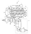
図1は、本発明の実施の形態に係る可変容量型ターボチャージャ20が適用されるディーゼルエンジン1の構成図である。
Embodiments of the present invention will be described below with reference to the drawings.
FIG. 1 is a configuration diagram of a diesel engine 1 to which a variable capacity turbocharger 20 according to an embodiment of the present invention is applied.

まず、構成について説明する。
過給機としての可変容量型ターボチャージャ20は、車両に搭載され、内燃機関としてのディーゼルエンジン1の一部を構成している。この内燃機関は、ディーゼルエンジン以外のものでもよく、例えば、ガソリンやエタノールなどの液体を燃料とする内燃機関であってもよい。
First, the configuration will be described.
A variable capacity turbocharger 20 as a supercharger is mounted on a vehicle and constitutes a part of a diesel engine 1 as an internal combustion engine. This internal combustion engine may be other than a diesel engine, for example, an internal combustion engine using a liquid such as gasoline or ethanol as fuel.

図1に示すように、ディーゼルエンジン1は、その種類、型式などのエンジン仕様は任意に選択され、例えば、直列4気筒などの公知のディーゼルエンジンで構成されている。具体的には、ディーゼルエンジン1は、エンジン本体2と、エンジン本体2に燃料を供給する燃料供給装置3と、吸気管4と、吸気管4に設けられたエアクリーナ5と、インタークーラ6およびスロットルバルブ7と、排気管8と、エンジン本体2から排出される排気ガスの一部を吸気管4内に還流させるEGR(Exhaust Gas Recirculation)装置9と、排気管8に設けられた排気ガス後処理装置11と、可変容量型ターボチャージャ20とを含んで構成されている。   As shown in FIG. 1, the diesel engine 1 has an engine specification such as its type and model arbitrarily selected, and is configured by a known diesel engine such as an in-line four cylinder. Specifically, the diesel engine 1 includes an engine body 2, a fuel supply device 3 that supplies fuel to the engine body 2, an intake pipe 4, an air cleaner 5 provided in the intake pipe 4, an intercooler 6, and a throttle. A valve 7, an exhaust pipe 8, an EGR (Exhaust Gas Recirculation) device 9 that recirculates part of the exhaust gas discharged from the engine body 2 into the intake pipe 4, and exhaust gas post-processing provided in the exhaust pipe 8 The apparatus 11 includes a variable capacity turbocharger 20.

エンジン本体2は、シリンダ21と、吸気装置22と、排気装置23と、インジェクタ24と、コモンレール25と、排気装置23内に燃料を噴射する排気用インジェクタ26とを含んで構成されている。   The engine main body 2 includes a cylinder 21, an intake device 22, an exhaust device 23, an injector 24, a common rail 25, and an exhaust injector 26 that injects fuel into the exhaust device 23.

シリンダ21は、4個のシリンダ21a、21b、21c、21dから構成されており、シリンダ21a〜21dには、それぞれ図示しない吸気ポートを介して吸気装置22が接続されるとともに、それぞれ図示しない排気ポートを介して排気装置23が接続されている。   The cylinder 21 is composed of four cylinders 21a, 21b, 21c, and 21d. An intake device 22 is connected to each of the cylinders 21a to 21d via an intake port (not shown), and an exhaust port (not shown). The exhaust device 23 is connected via

吸気装置22は、吸気通路を有するとともに、一端部で4個に分岐された分岐部22a、22b、22c、22dを有している。吸気装置22は、他方端部で吸気管4に連結され、分岐部22a〜22dの各端部でエンジン本体2の各吸気ポートに連結されている。   The intake device 22 has an intake passage and branch portions 22a, 22b, 22c, and 22d that are branched into four at one end. The intake device 22 is connected to the intake pipe 4 at the other end, and is connected to each intake port of the engine body 2 at each end of the branch portions 22a to 22d.

吸気装置22においては、吸気管4から供給された空気が分岐部22a〜22dから各吸気ポートを介してシリンダ21a〜21dに供給されるようになっている。   In the intake device 22, the air supplied from the intake pipe 4 is supplied from the branch portions 22a to 22d to the cylinders 21a to 21d via the intake ports.

排気装置23は、一方端部で4個に分岐された分岐部23a、23b、23c、23dを有するとともに、分岐部23a〜23dの一端がエンジン本体2の各排気ポートに連結され、他方端部で分岐部23a〜23dが集合するとともに可変容量型ターボチャージャ20に連結される集合管23eを有している。集合管23eには、EGR装置9が接続されており、シリンダ21a〜21dから排出される排気ガスの一部がEGR装置9に流入するようになっている。   The exhaust device 23 includes branch portions 23a, 23b, 23c, and 23d that are branched into four at one end, and one end of each of the branch portions 23a to 23d is connected to each exhaust port of the engine body 2, and the other end. The branch portions 23a to 23d are gathered and have a collecting pipe 23e connected to the variable capacity turbocharger 20. The EGR device 9 is connected to the collecting pipe 23e, and a part of the exhaust gas discharged from the cylinders 21a to 21d flows into the EGR device 9.

インジェクタ24は、4個のインジェクタ24a、24b、24c、24dから構成され、それぞれ燃料噴射ノズルを有しシリンダ21a〜21dに設けられており、燃料噴射ノズルからシリンダ21a〜21d内に燃料を噴射して霧状にするようになっている。   The injector 24 includes four injectors 24a, 24b, 24c, and 24d, each having a fuel injection nozzle and provided in the cylinders 21a to 21d, and injecting fuel into the cylinders 21a to 21d from the fuel injection nozzle. To make it foggy.

コモンレール25は、燃料供給装置3から供給された高圧の燃料を蓄圧する図示しない蓄圧部を有し、インジェクタ24a〜24dに連結されており、インジェクタ24a〜24dに高圧燃料を配給するようになっている。   The common rail 25 has a pressure accumulating portion (not shown) that accumulates high-pressure fuel supplied from the fuel supply device 3, and is connected to the injectors 24a to 24d, and distributes high-pressure fuel to the injectors 24a to 24d. Yes.

排気用インジェクタ26は、インジェクタ24と同様に燃料噴射ノズルを有し、集合管23e内に設けられており、集合管23eの排気通路内に燃料をポスト噴射して排気ガスに燃料を添加するようになっている。このポスト噴射により、排気ガス後処理装置11を昇温させて処理効率を高めるとともに、排気ガス後処理装置11に堆積したPM(Paticulate Matter:粒子状物質)などの堆積物の酸化を促進させ、目詰まりを防止するようにしている。   Similarly to the injector 24, the exhaust injector 26 has a fuel injection nozzle and is provided in the collecting pipe 23e. Post-injection of fuel into the exhaust passage of the collecting pipe 23e is performed to add fuel to the exhaust gas. It has become. By this post-injection, the exhaust gas aftertreatment device 11 is heated to increase the treatment efficiency, and the oxidation of deposits such as PM (Particulate Matter) deposited on the exhaust gas aftertreatment device 11 is promoted, I try to prevent clogging.

燃料供給装置3は、図示しない燃料タンクおよび燃料ポンプと、燃料供給管3a、3bとを含んで構成されており、燃料タンク内の燃料を燃料ポンプにより高圧にしてコモンレール25および排気用インジェクタ26に供給するようになっている。   The fuel supply device 3 includes a fuel tank and a fuel pump (not shown), and fuel supply pipes 3a and 3b. The fuel in the fuel tank is made high by the fuel pump and is supplied to the common rail 25 and the exhaust injector 26. It comes to supply.

吸気管4は、図示しない吸気口から吸入した新気を吸気装置22に導入する配管からなり、吸気通路4aを有しており、可変容量型ターボチャージャ20に連結され吸気通路4a内の新気が可変容量型ターボチャージャ20を経由して吸気装置22に導入されるようになっている。また、吸気通路4a内の新気は、吸気管4に設けられたエアクリーナ5により浄化され、さらに吸気管4に設けられたインタークーラ6により冷却されて密度が高められるようになっている。   The intake pipe 4 is composed of a pipe for introducing fresh air drawn from an intake port (not shown) into the intake device 22 and has an intake passage 4a. The intake pipe 4 is connected to the variable capacity turbocharger 20 and is fresh in the intake passage 4a. Is introduced into the intake device 22 via the variable displacement turbocharger 20. Further, fresh air in the intake passage 4 a is purified by an air cleaner 5 provided in the intake pipe 4, and further cooled by an intercooler 6 provided in the intake pipe 4 to increase the density.

スロットルバルブ7は、例えば、バタフライバルブなどの絞り弁からなり、インタークーラ6を通過した新気のエンジン内部への流入量を調整するようになっている。   The throttle valve 7 is composed of a throttle valve such as a butterfly valve, for example, and adjusts the amount of fresh air that has passed through the intercooler 6 into the engine.

排気管8は、排気装置23の集合管23eから排出される排気ガスを大気に放出させる配管からなり、排気通路8aを有し、一端が集合管23eに連結されている。この排気管8には、排気ガス後処理装置11が設けられており、排気ガス中の有害物質が除去されるようになっている。また、排気管8には、排気ガス後処理装置11の下流側に図示しないマフラーなどの消音装置が設けられている。   The exhaust pipe 8 is a pipe that discharges exhaust gas discharged from the collecting pipe 23e of the exhaust device 23 to the atmosphere, has an exhaust passage 8a, and one end is connected to the collecting pipe 23e. The exhaust pipe 8 is provided with an exhaust gas after-treatment device 11 so that harmful substances in the exhaust gas are removed. Further, the exhaust pipe 8 is provided with a silencer such as a muffler (not shown) on the downstream side of the exhaust gas aftertreatment device 11.

EGR装置9は、EGR管31と、EGRバルブ32と、EGRクーラ33とを含んで構成されており、排気装置23の排気通路8a内の排気ガスを吸気装置22の吸気通路4a内に還流させるようになっている。   The EGR device 9 includes an EGR pipe 31, an EGR valve 32, and an EGR cooler 33, and recirculates exhaust gas in the exhaust passage 8a of the exhaust device 23 into the intake passage 4a of the intake device 22. It is like that.

EGR管31は、EGR通路を有しており、EGR管31の吸気装置22側には、EGRバルブ32が設けられ、EGR管31の排気装置23側には、EGRクーラ33が設けられている。   The EGR pipe 31 has an EGR passage, and an EGR valve 32 is provided on the intake device 22 side of the EGR pipe 31, and an EGR cooler 33 is provided on the exhaust device 23 side of the EGR pipe 31. .

EGRバルブ32は、その開度が図示しない電子制御ユニット(ECU:Electronic Control Unit)により制御され、吸気通路内に還流される排気ガスの量が調整されるようになっている。また、EGRクーラ33により、還流される排気ガスの温度が下げられ、その密度が高められるようになっている。   The opening degree of the EGR valve 32 is controlled by an electronic control unit (ECU: Electronic Control Unit) (not shown) so that the amount of exhaust gas recirculated into the intake passage is adjusted. The EGR cooler 33 reduces the temperature of the recirculated exhaust gas and increases its density.

排気ガス後処理装置11は、NSR触媒(NOx Storage−reduction Catalyst)34と、DPNR触媒(Diesel Paticulate−NOx Reduction catalyst)35と、酸化触媒36と、排気温センサ37、差圧センサ38と、空燃比センサ39とを含んで構成されている。   The exhaust gas aftertreatment device 11 includes an NSR catalyst (NOx storage-reduction catalyst) 34, a DPNR catalyst (diesel particulate-NOx reduction catalyst) 35, an oxidation catalyst 36, an exhaust temperature sensor 37, a differential pressure sensor 38, A fuel ratio sensor 39 is included.

NSR触媒34は、NOx吸蔵物質を含んで構成されており、排気空燃比がリーンのときに排気ガス中のNOxを吸蔵し、排気空燃比がリッチになったときに吸蔵していたNOxを還元させて排気ガス中のNOxを低減するようになっている。   The NSR catalyst 34 is configured to contain a NOx occlusion substance, occludes NOx in the exhaust gas when the exhaust air-fuel ratio is lean, and reduces the NOx occluded when the exhaust air-fuel ratio becomes rich. Thus, NOx in the exhaust gas is reduced.

DPNR触媒35は、PMを酸化させる性能を有するNOx吸蔵還元触媒が塗布された多孔質セラミックからなり、排気ガス中のPMを捕集し、これを排気ガス中のNOxと同時に浄化させるようになっている。これらの浄化の際には、PMが酸化されるとともに、CO(一酸化炭素)やHC(炭化水素)も酸化され、NOxが還元される。   The DPNR catalyst 35 is made of a porous ceramic coated with a NOx storage reduction catalyst having the ability to oxidize PM. The DPNR catalyst 35 collects PM in the exhaust gas and purifies it simultaneously with NOx in the exhaust gas. ing. During these purifications, PM is oxidized, CO (carbon monoxide) and HC (hydrocarbon) are also oxidized, and NOx is reduced.

酸化触媒36は、各種ガスに対して酸化活性のある白金、パラジウムなどの触媒金属からなり、排気ガス中の有害物質、例えば、HCを酸化させ、CO2(二酸化炭素)およびH2O(水蒸気)に分解処理するようになっている。   The oxidation catalyst 36 is made of a catalytic metal such as platinum or palladium that has an oxidation activity with respect to various gases, and oxidizes harmful substances in the exhaust gas, for example, HC, to be decomposed into CO2 (carbon dioxide) and H2O (water vapor). It comes to handle.

排気温センサ37は、サーミスタなどの検出素子からなり、温度変化を抵抗値変化として検出するようになっている。
差圧センサ38は、圧力センサからなり、NSR触媒34の上流側の排気ガスの圧力とDPNR触媒35の下流側の排気ガスの圧力との差圧を検出することにより、DPNR触媒35のPMによる目詰まりを検出するようになっている。
The exhaust temperature sensor 37 includes a detection element such as a thermistor, and detects a temperature change as a resistance value change.
The differential pressure sensor 38 is composed of a pressure sensor, and detects the differential pressure between the pressure of the exhaust gas upstream of the NSR catalyst 34 and the pressure of the exhaust gas downstream of the DPNR catalyst 35, thereby determining the PM of the DPNR catalyst 35. It is designed to detect clogging.

空燃比センサ39は、ジルコニア素子などの検出素子からなり、酸素濃度差に応じた電力を検出することにより排気ガス中の酸素濃度を検出するようになっている。
排気温センサ37、差圧センサ38および空燃比センサ39から検出された情報は、図示しない電子制御ユニットに送られるようになっている。
The air-fuel ratio sensor 39 includes a detection element such as a zirconia element, and detects the oxygen concentration in the exhaust gas by detecting electric power according to the oxygen concentration difference.
Information detected from the exhaust temperature sensor 37, the differential pressure sensor 38, and the air-fuel ratio sensor 39 is sent to an electronic control unit (not shown).

次いで、本実施の形態に係る可変容量型ターボチャージャ20の構成について、図面を参照し説明する。
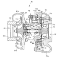
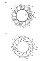
図2は、本発明の実施の形態に係る可変容量型ターボチャージャ20の断面図である。図3は、本発明の実施の形態に係る可変容量型ターボチャージャ20の可変ノズル機構を示す側面図であり、(a)は、図2中左方より可変ノズル機構を見た側面図を示し、(b)は、図2中右方より可変ノズル機構を見た側面図を示す。
Next, the configuration of the variable capacity turbocharger 20 according to the present embodiment will be described with reference to the drawings.
FIG. 2 is a cross-sectional view of the variable capacity turbocharger 20 according to the embodiment of the present invention. 3 is a side view showing the variable nozzle mechanism of the variable capacity turbocharger 20 according to the embodiment of the present invention. FIG. 3A is a side view of the variable nozzle mechanism as viewed from the left in FIG. (B) shows the side view which looked at the variable nozzle mechanism from the right side in FIG.

図2に示すように、可変容量型ターボチャージャ20は、ベアリングハウジング41と、タービン42と、コンプレッサ43と、アクチュエータ44と、可変ノズル機構45と、遮熱板50とを含んで構成されており、排気装置23(図1参照)から排出される排気ガスのエネルギを利用してタービン42を回転させ、その動力でコンプレッサ43を駆動させて大気圧よりも高い圧力の新気を吸気装置22(図1参照)内に供給するようになっている。   As shown in FIG. 2, the variable displacement turbocharger 20 includes a bearing housing 41, a turbine 42, a compressor 43, an actuator 44, a variable nozzle mechanism 45, and a heat shield plate 50. Then, the turbine 42 is rotated using the energy of the exhaust gas discharged from the exhaust device 23 (see FIG. 1), and the compressor 43 is driven by the motive power to generate fresh air having a pressure higher than the atmospheric pressure by the intake device 22 ( (See FIG. 1).

ベアリングハウジング41は、外周部に周方向全周に亘って形成され、タービン42に連結するフランジ部41aと、コンプレッサ43に連結するフランジ部41bと、一対のベアリング部41cとを含んで構成されている。   The bearing housing 41 is formed on the outer peripheral portion over the entire circumference, and includes a flange portion 41a connected to the turbine 42, a flange portion 41b connected to the compressor 43, and a pair of bearing portions 41c. Yes.

一対のベアリング部41cは、例えばフルフロートタイプのベアリングで構成されており、回転軸62を回転自在に支持するようになっている。すなわち、ベアリングハウジング41は、一対のベアリング部41cを介して回転軸62を回転自在に支持するとともに、回転軸62を収容するようになっている。   The pair of bearing portions 41c is constituted by, for example, a full float type bearing, and supports the rotating shaft 62 rotatably. That is, the bearing housing 41 is configured to rotatably support the rotating shaft 62 via the pair of bearing portions 41 c and to accommodate the rotating shaft 62.

また、回転軸62の一方端部には、後述するタービンホイール73が連結され、他方端部には後述するコンプレッサホイール83が連結されており、回転軸62とともにタービンホイール73およびコンプレッサホイール83が回転するようになっている。   A turbine wheel 73 described later is connected to one end of the rotating shaft 62, and a compressor wheel 83 described later is connected to the other end, and the turbine wheel 73 and the compressor wheel 83 rotate together with the rotating shaft 62. It is supposed to be.

また、ベアリングハウジング41には、ウォータジャケット41dがベアリング部41cの近傍に設けられており、ベアリング部41cの近傍が冷却され、回転軸62の焼き付きが防止されるようになっている。   Further, the bearing housing 41 is provided with a water jacket 41d in the vicinity of the bearing portion 41c so that the vicinity of the bearing portion 41c is cooled and seizure of the rotating shaft 62 is prevented.

タービン42は、タービンハウジング71と、タービンホイール73とを含んで構成されており、タービンホイール73は、回転軸62に連結されるようになっている。   The turbine 42 includes a turbine housing 71 and a turbine wheel 73, and the turbine wheel 73 is connected to the rotary shaft 62.

タービンハウジング71には、排気ガスを旋回させるスクロール通路71aと、スクロール通路71a内の排気ガスを、タービンホイール73に向けて流通させる環状のガス流路71bと、タービンホイール73を介して排出される排気ガスを通す排気ガス通路71cとが形成されている。   The turbine housing 71 is discharged through a scroll passage 71 a for turning the exhaust gas, an annular gas passage 71 b for passing the exhaust gas in the scroll passage 71 a toward the turbine wheel 73, and the turbine wheel 73. An exhaust gas passage 71c through which the exhaust gas passes is formed.

タービンハウジング71の一方端部は、図1に示す上流側の排気管8と連結されており、上流側の排気管8内の排気通路8aとスクロール通路71aとが連通し、排気通路8a内の排気ガスがスクロール通路71a内に流入するようになっている。一方、タービンハウジング71の他方端部は、図1に示す下流側の排気管8と連結されており、下流側の排気管8内の排気通路8aと排気ガス通路71cとが連通し、排気ガス通路71c内の排気ガスが下流側の排気管8内の排気通路8aに排出されるようになっている。また、ガス流路71bは、排気通路8aと連通するスクロール通路71a内に流入した排気ガスをタービンホイール73に導入するようになっている。なお、本実施の形態におけるガス流路71bは、本発明における排気ガス導入通路を構成している。   One end of the turbine housing 71 is connected to the upstream exhaust pipe 8 shown in FIG. 1, and the exhaust passage 8a in the upstream exhaust pipe 8 and the scroll passage 71a communicate with each other. Exhaust gas flows into the scroll passage 71a. On the other hand, the other end portion of the turbine housing 71 is connected to the downstream exhaust pipe 8 shown in FIG. 1, and the exhaust passage 8a and the exhaust gas passage 71c in the downstream exhaust pipe 8 communicate with each other. The exhaust gas in the passage 71c is discharged to the exhaust passage 8a in the exhaust pipe 8 on the downstream side. Further, the gas flow path 71b introduces exhaust gas that has flowed into the scroll passage 71a communicating with the exhaust passage 8a into the turbine wheel 73. The gas flow path 71b in the present embodiment constitutes an exhaust gas introduction passage in the present invention.

また、タービンハウジング71は、回転軸62の軸方向であってコンプレッサ43側の内周端面71dにおいて、前述のベアリングハウジング41のフランジ部41aに取付けられ、タービンホイール73を内部に収容するようになっている。   The turbine housing 71 is attached to the flange portion 41a of the bearing housing 41 on the inner peripheral end surface 71d on the compressor 43 side in the axial direction of the rotary shaft 62, and accommodates the turbine wheel 73 therein. ing.

タービン42においては、上流側の排気管8内の排気通路8aからスクロール通路71a内に流入した排気ガスがガス流路71bを通ってタービンホイール73に導入され、排気ガスの流動圧力によりタービンホイール73が回転するようになっている。   In the turbine 42, the exhaust gas flowing into the scroll passage 71a from the exhaust passage 8a in the upstream exhaust pipe 8 is introduced into the turbine wheel 73 through the gas passage 71b, and the turbine wheel 73 is caused by the flow pressure of the exhaust gas. Is designed to rotate.

コンプレッサ43は、コンプレッサハウジング81と、コンプレッサホイール83とを含んで構成されており、コンプレッサホイール83は、回転軸62に連結されるようになっている。   The compressor 43 includes a compressor housing 81 and a compressor wheel 83, and the compressor wheel 83 is connected to the rotating shaft 62.

コンプレッサハウジング81には、図1に示すエアクリーナ5を通過し浄化された吸入空気を、コンプレッサホイール83に向けて導入させる導入通路81aと、コンプレッサホイール83の回転により圧力が高められた吸入空気を吸気管4の吸気通路4aに排出させる排出通路81bと、コンプレッサホイール83で圧縮された吸入空気を排出通路81b内に流入させる流入通路81cとが形成されている。   In the compressor housing 81, intake air 81 a that introduces purified air that has passed through the air cleaner 5 shown in FIG. 1 toward the compressor wheel 83, and intake air whose pressure has been increased by the rotation of the compressor wheel 83 is taken in. A discharge passage 81b for discharging to the intake passage 4a of the pipe 4 and an inflow passage 81c for allowing the intake air compressed by the compressor wheel 83 to flow into the discharge passage 81b are formed.

コンプレッサハウジング81の一方端部は、図1に示す上流側の吸気管4と連結されており、上流側の吸気管4内の吸気通路4aと導入通路81aとが連通し、吸気通路4a内の吸入空気が導入通路81a内に流入するようになっている。一方、コンプレッサハウジング81の他方端部は、下流側の吸気管4と連結されており、下流側の吸気管4内の吸気通路4aと排出通路81bとが連通し、排出通路81b内の吸入空気が下流側の吸気管4内の吸気通路4aに排出されるようになっている。   One end of the compressor housing 81 is connected to the upstream side intake pipe 4 shown in FIG. 1, and the intake passage 4a in the upstream side intake pipe 4 and the introduction passage 81a communicate with each other. The intake air flows into the introduction passage 81a. On the other hand, the other end portion of the compressor housing 81 is connected to the downstream intake pipe 4, and the intake passage 4a and the discharge passage 81b in the downstream intake pipe 4 communicate with each other, and the intake air in the discharge passage 81b. Is discharged to the intake passage 4a in the intake pipe 4 on the downstream side.

コンプレッサ43においては、上流側の吸気管4内の吸気通路4aから導入通路81a内に導入された吸入空気は、コンプレッサホイール83に導入され、コンプレッサホイール83の回転により圧力が高められて、流入通路81cを介して排出通路81b内に排出されるようになっている。   In the compressor 43, the intake air introduced into the introduction passage 81a from the intake passage 4a in the intake pipe 4 on the upstream side is introduced into the compressor wheel 83, and the pressure is increased by the rotation of the compressor wheel 83, so that the inflow passage It is discharged into the discharge passage 81b through 81c.

アクチュエータ44は、図示しない駆動部に連結されるとともに、後述する可変ノズル機構45に連結されており、前述の電子制御ユニットにより車両の運転状態に応じて制御されることによって、可変ノズル機構45を作動させるようになっている。   The actuator 44 is connected to a drive unit (not shown) and is connected to a variable nozzle mechanism 45 to be described later. The actuator 44 is controlled by the electronic control unit according to the driving state of the vehicle. It is designed to operate.

可変ノズル機構45は、図2ないし図3(a)、(b)に示すように、タービンハウジング71のガス流路71b内に配置された複数のベーン91と、ベーン91を軸92を介して回動可能に支持するノズルプレート93と、各軸92の端部に固定されたアーム94を介して軸92を回動させるユニゾンリング95と、一端部でユニゾンリング95に回動可能に係合し、他端部でリンクシャフト96に固定された従動リンク97と、ベアリングハウジング41に設けられリンクシャフト96を回動可能に支持するブッシュ98と、一端部でリンクシャフト96に固定され、他端部でアクチュエータ44に固定された駆動リンク101とを含んで構成されている。   As shown in FIGS. 2 to 3A and 3B, the variable nozzle mechanism 45 includes a plurality of vanes 91 disposed in the gas flow path 71 b of the turbine housing 71, and the vanes 91 via a shaft 92. A nozzle plate 93 that is rotatably supported, a unison ring 95 that rotates the shaft 92 via an arm 94 that is fixed to the end of each shaft 92, and a unison ring 95 that is pivotably engaged at one end. A driven link 97 fixed to the link shaft 96 at the other end, a bush 98 provided on the bearing housing 41 to rotatably support the link shaft 96, and an end fixed to the link shaft 96 at the other end. And a drive link 101 fixed to the actuator 44 at a portion.

この可変ノズル機構45においては、複数のベーン91により、排気ガスの流入容量を可変にする複数のベーンノズル45aが画成されており、この複数のベーンノズル45aを通って排気ガスがタービン42のスクロール通路71aからタービンホイール73に向けて流入するようになっている。   In the variable nozzle mechanism 45, a plurality of vane nozzles 45 a that vary the inflow capacity of the exhaust gas are defined by the plurality of vanes 91, and the exhaust gas passes through the plurality of vane nozzles 45 a and the scroll passage of the turbine 42. It flows into the turbine wheel 73 from 71a.

また、可変ノズル機構45においては、ユニゾンリング95を回動させ、ユニゾンリング95と係合しているアーム94を軸92を中心にして回動させることにより、ベーン91の開度が変わるよう構成されている。このユニゾンリング95は、従動リンク97、リンクシャフト96および駆動リンク101を介してアクチュエータ44に連結されており、このアクチュエータ44の作動によりベーン91の開度が変わるようになっている。ベーン91の開度が変わることにより、タービンハウジング71のガス流路71bに流入し各ベーン91の間を流通して、タービンホイール73に流入する排気ガスの流速を可変できるようになっている。これによりタービンホイール73の回転速度を可変することができるので、コンプレッサホイール83の回転速度を可変することができ、コンプレッサ43により圧縮される吸入空気の過給圧を可変できるようになっている。   The variable nozzle mechanism 45 is configured such that the opening degree of the vane 91 is changed by rotating the unison ring 95 and rotating the arm 94 engaged with the unison ring 95 about the shaft 92. Has been. The unison ring 95 is connected to the actuator 44 through a driven link 97, a link shaft 96, and a drive link 101, and the opening degree of the vane 91 is changed by the operation of the actuator 44. By changing the opening degree of the vane 91, the flow rate of the exhaust gas flowing into the gas passage 71 b of the turbine housing 71 and flowing between the vanes 91 and flowing into the turbine wheel 73 can be varied. As a result, the rotational speed of the turbine wheel 73 can be varied, so that the rotational speed of the compressor wheel 83 can be varied, and the supercharging pressure of the intake air compressed by the compressor 43 can be varied.

遮熱板50は、ベアリングハウジング41とタービンハウジング71との間に介装され、ガス流路71bから流入される高温の排気ガスがベアリングハウジング41に接するのを防止するとともに、排気ガスの熱を遮蔽するようになっている。なお、遮熱板50の詳細については、後述する。   The heat shield plate 50 is interposed between the bearing housing 41 and the turbine housing 71 to prevent the high-temperature exhaust gas flowing in from the gas flow path 71b from coming into contact with the bearing housing 41 and to remove the heat of the exhaust gas. It is designed to shield. The details of the heat shield plate 50 will be described later.

次に、遮熱板50の構成について、図4を参照して詳しく説明する。
図4は、図2の一部を拡大した部分拡大断面図である。また、図5は、本発明の実施の形態に係る可変容量型ターボチャージャ20の遮熱板50の構成を示す図であり、(a)は、遮熱板50を図2中、右方向から見た正面図を示し、(b)は、(a)のA−A断面を示す断面図である。
Next, the configuration of the heat shield plate 50 will be described in detail with reference to FIG.
FIG. 4 is a partially enlarged cross-sectional view in which a part of FIG. 2 is enlarged. 5 is a diagram showing the configuration of the heat shield 50 of the variable capacity turbocharger 20 according to the embodiment of the present invention. FIG. 5A shows the heat shield 50 from the right in FIG. The seen front view is shown, (b) is sectional drawing which shows the AA cross section of (a).

図4に示すように、可変容量型ターボチャージャ20のタービン42側には、フランジ部41aを含むベアリングハウジング41の外周面とタービンハウジング71の内周面とノズルプレート93のコンプレッサ43(図2参照)側の側面とによりリンク室102が画成されている。   As shown in FIG. 4, on the turbine 42 side of the variable capacity turbocharger 20, the outer peripheral surface of the bearing housing 41 including the flange portion 41a, the inner peripheral surface of the turbine housing 71, and the compressor 43 of the nozzle plate 93 (see FIG. 2). The link chamber 102 is defined by the side surface on the) side.

ここで、リンク室102を画成するタービンハウジング71の内周面とノズルプレート93の外周端面との間には、少なからず隙間が存在する。そのため、スクロール通路71a内の排気圧力が上昇し、リンク室102内の排気圧力よりも高くなると、スクロール通路71a内を流通する水蒸気を含む高温の排気ガスがガス流路71bを介してタービンホイール73に導入される際に、前述のタービンハウジング71の内周面とノズルプレート93の外周端面との間の隙間を介してリンク室102内に流入することがある。   Here, there is not a little gap between the inner peripheral surface of the turbine housing 71 that defines the link chamber 102 and the outer peripheral end surface of the nozzle plate 93. For this reason, when the exhaust pressure in the scroll passage 71a rises and becomes higher than the exhaust pressure in the link chamber 102, the high-temperature exhaust gas including water vapor that circulates in the scroll passage 71a passes through the gas passage 71b and the turbine wheel 73. May be introduced into the link chamber 102 through a gap between the inner peripheral surface of the turbine housing 71 and the outer peripheral end surface of the nozzle plate 93.

このように、リンク室102内に水蒸気を含む高温の排気ガスが流入するおそれがあるため、リンク室102を画成するベアリングハウジング41の外周面に直接、水蒸気を含む高温の排気ガスが接することを避けるべく、このベアリングハウジング41のリンク室102に対向する面に密着するよう遮熱板50が設けられている。   As described above, since there is a possibility that the high-temperature exhaust gas containing water vapor flows into the link chamber 102, the high-temperature exhaust gas containing water vapor directly contacts the outer peripheral surface of the bearing housing 41 that defines the link chamber 102. In order to avoid this, a heat shield 50 is provided so as to be in close contact with the surface of the bearing housing 41 facing the link chamber 102.

また、ベアリングハウジング41のフランジ部41aのタービンハウジング側端面41eとタービンハウジング71のフランジ部側内周面71eとの間には、フランジ部41aの周方向全周に亘って間隙部104が形成されている。   Further, a gap 104 is formed between the turbine housing side end surface 41e of the flange portion 41a of the bearing housing 41 and the flange portion side inner peripheral surface 71e of the turbine housing 71 over the entire circumferential direction of the flange portion 41a. ing.

図5(a)、(b)に示すように、遮熱板50は、円板状の例えばステンレス鋼板などの熱伝導率の低い部材によって構成されており、リンク室102を画成するベアリングハウジング41のフランジ部41aを覆う環状の底面部51と、リンク室102を画成するベアリングハウジング41の外周面を覆う円筒状の側面部52とを含んで構成されている。   As shown in FIGS. 5 (a) and 5 (b), the heat shield plate 50 is made of a member having a low thermal conductivity, such as a disk-shaped stainless steel plate, and forms a link chamber 102. 41 includes an annular bottom surface portion 51 that covers the flange portion 41 a of the cylinder 41 and a cylindrical side surface portion 52 that covers the outer peripheral surface of the bearing housing 41 that defines the link chamber 102.

遮熱板50の底面部51の放射方向外端部には、周方向全周に亘ってタービンハウジング71側に屈曲する屈曲部51aが形成さている。この屈曲部51aは、ベアリングハウジング41の外周面に対向して開口する略断面U字状に形成されており、間隙部104に屈曲された状態で圧入されるようになっている。すなわち、遮熱板50は、この屈曲部51aの弾性力によって、放射方向外端部において、間隙部104を形成するタービンハウジング側端面41eとフランジ部側内周面71eとに密着するよう間隙部104に保持されるとともに、間隙部104におけるシール性が遮熱板50の放射方向外端部の周方向全周に亘って確保されるようになっている(図4参照)。
また、屈曲部51aの弾性力によって、遮熱板50がベアリングハウジング41の遮熱板対向面に密着するようになっている(図4参照)。
また、底面部51には、可変ノズル機構45におけるリンクシャフト96を通すためのリンクシャフト孔51bが形成されている。
A bent portion 51 a that is bent toward the turbine housing 71 is formed at the radially outer end of the bottom surface portion 51 of the heat shield plate 50 over the entire circumference. The bent portion 51 a is formed in a substantially U-shaped cross section that opens to face the outer peripheral surface of the bearing housing 41 and is press-fitted into the gap portion 104 in a bent state. That is, the heat shield plate 50 has a gap portion so as to be in close contact with the turbine housing side end surface 41e and the flange portion side inner peripheral surface 71e forming the gap portion 104 at the radially outer end portion by the elastic force of the bent portion 51a. While being held by 104, the sealing performance in the gap 104 is ensured over the entire circumference in the radial outer end of the heat shield 50 (see FIG. 4).
Further, the heat shield plate 50 is brought into close contact with the heat shield plate facing surface of the bearing housing 41 by the elastic force of the bent portion 51a (see FIG. 4).
In addition, a link shaft hole 51 b for allowing the link shaft 96 in the variable nozzle mechanism 45 to pass is formed in the bottom surface portion 51.

一方、側面部52は、上述の底面部51の放射方向内端部から鉛直方向(回転軸62の軸方向)に延在する円筒状に形成されており、ベアリングハウジング41の外周面を覆うようになっている。また、側面部52の先端部近傍には、放射内方に向けて突出した環状凸部52aが周方向全周に亘って形成されており、この環状凸部52aがベアリングハウジング41の外周面に押圧されることにより、遮熱板50をベアリングハウジング41に対して保持するようになっている。さらに、環状凸部52aは、遮熱板50の側面部52の先端部において、遮熱板50とベアリングハウジング41の外周面との間のシール性を確保するようになっている。   On the other hand, the side surface portion 52 is formed in a cylindrical shape extending in the vertical direction (the axial direction of the rotary shaft 62) from the radially inner end portion of the bottom surface portion 51, and covers the outer peripheral surface of the bearing housing 41. It has become. Further, an annular convex portion 52 a that protrudes radially inward is formed in the vicinity of the distal end portion of the side surface portion 52, and this annular convex portion 52 a is formed on the outer peripheral surface of the bearing housing 41. By being pressed, the heat shield plate 50 is held against the bearing housing 41. Further, the annular convex portion 52 a ensures a sealing property between the heat shield plate 50 and the outer peripheral surface of the bearing housing 41 at the tip of the side surface portion 52 of the heat shield plate 50.

次いで、遮熱板50の底面部51の放射方向外端部に形成された屈曲部51aの作用について、図6を参照して説明する。
図6は、本発明の実施の形態に係る可変容量型ターボチャージャ20の遮熱板50の作用を説明する一部拡大断面図である。
Next, the action of the bent portion 51a formed at the radially outer end portion of the bottom surface portion 51 of the heat shield plate 50 will be described with reference to FIG.
FIG. 6 is a partially enlarged sectional view for explaining the operation of the heat shield 50 of the variable capacity turbocharger 20 according to the embodiment of the present invention.

図6に示すように、間隙部104に屈曲部51aが屈曲された状態で圧入された際、遮熱板50は、この屈曲部51aの弾性力によって、放射方向外端部において、間隙部104を形成するタービンハウジング側端面41eとフランジ部側内周面71eとに密着するよう間隙部104に保持されるとともに、間隙部104におけるシール性が遮熱板50の放射方向外端部の周方向全周に亘って確保される。これにより、水蒸気を含む高温の排気ガスがリンク室102に流入した場合であっても、間隙部104におけるシール性を向上させることができる。   As shown in FIG. 6, when the bent portion 51a is press-fitted into the gap portion 104, the heat shield plate 50 has a gap portion 104 at the radially outer end due to the elastic force of the bent portion 51a. Is held in the gap 104 so as to be in close contact with the turbine housing side end surface 41e and the flange side inner peripheral surface 71e, and the sealing performance in the gap 104 is the circumferential direction of the radially outer end of the heat shield plate 50. Secured over the entire circumference. Thereby, even if the high-temperature exhaust gas containing water vapor flows into the link chamber 102, the sealing performance in the gap 104 can be improved.

さらに、水蒸気を含む高温の排気ガスがリンク室102に流入した場合においては、屈曲部51aの内周面には、図中矢印で示されるような排気ガスの内圧がかかる。屈曲部51aは、この排気ガスの内圧がかかることにより、放射外方に押し広げられる。これにより、遮熱板50は、放射方向外端部の周方向全周に亘って形成された屈曲部51aにおいて、略断面U字状に形成された屈曲部51aの弾性力に加えて、排気ガスの内圧によって、より確実に間隙部104を形成するタービンハウジング側端面41eとフランジ部側内周面71eとに密着する。このため、水蒸気を含む高温の排気ガスがリンク室102に流入した場合であっても、間隙部104におけるシール性を確保することができる。   Further, when a high-temperature exhaust gas containing water vapor flows into the link chamber 102, the internal pressure of the exhaust gas as shown by the arrows in the drawing is applied to the inner peripheral surface of the bent portion 51a. The bent portion 51a is expanded outwardly when the internal pressure of the exhaust gas is applied. Thereby, in addition to the elastic force of the bending part 51a formed in the substantially cross-sectional U-shape in the bending part 51a formed over the perimeter of the circumferential direction of the radial direction outer end part, the heat shield 50 is exhausted. By the internal pressure of the gas, the turbine housing side end surface 41e and the flange portion side inner peripheral surface 71e, which form the gap 104, are more closely attached. For this reason, even when high-temperature exhaust gas containing water vapor flows into the link chamber 102, the sealing performance in the gap 104 can be ensured.

以上のように、本発明の実施の形態に係る可変容量型ターボチャージャは、遮熱板50の放射方向外端部に周方向全周に亘って形成された屈曲部51aが間隙部104に屈曲された状態で圧入されるので、遮熱板50のガタツキを防止でき、このガタツキに起因した遮熱板50の摩耗を防止できるとともに、遮熱板50の放射方向外端部の周方向全周に亘ってタービンハウジング71とベアリングハウジング41との間のシール性を向上させることができる。   As described above, in the variable capacity turbocharger according to the embodiment of the present invention, the bent portion 51a formed at the radially outer end portion of the heat shield plate 50 over the entire circumference is bent into the gap portion 104. Therefore, the heat shield plate 50 can be prevented from rattling, the wear of the heat shield plate 50 due to the rattle can be prevented, and the radial outer end of the heat shield plate 50 in the circumferential direction. Thus, the sealing performance between the turbine housing 71 and the bearing housing 41 can be improved.

また、屈曲部51aの弾性力によって遮熱板50がタービンハウジング71またはベアリングハウジング41の遮熱板対向面に密着させることができるので、水蒸気を含む高温の排気ガスにベアリングハウジング41が晒されるのを防止して、凝縮水の発生を抑制することができ、凝縮水の付着によるベアリングハウジング41の腐食を防止することができる。   Further, since the heat shield plate 50 can be brought into close contact with the heat shield plate facing surface of the turbine housing 71 or the bearing housing 41 by the elastic force of the bent portion 51a, the bearing housing 41 is exposed to high-temperature exhaust gas containing water vapor. Therefore, the generation of condensed water can be suppressed, and corrosion of the bearing housing 41 due to the adhesion of condensed water can be prevented.

また、屈曲部51aがベアリングハウジング41の外周面に対向して開口する略断面U字状に形成されているので、水蒸気を含む高温の排気ガスがリンク室102に流入した際には、この排気ガスの内圧により略断面U字状に開口した屈曲部51aが間隙部104に圧入された状態で押し広げられる。そのため、屈曲部51aの弾性力に加えて排気ガスの内圧により、間隙部104を形成するタービンハウジング側端面41eおよびフランジ部側内周面71eに屈曲部51aが密着した状態となるので、遮熱板50のガタツキを確実に防止して、このガタツキに起因した遮熱板50の摩耗をより確実に防止するとともに、間隙部104において遮熱板50の放射外端部の周方向全周に亘って、タービンハウジング71とベアリングハウジング41との間のシール性を確保することができる。さらに、屈曲部51aの弾性力に加えて排気ガスの内圧によって、遮熱板50をタービンハウジング71またはベアリングハウジング41の遮熱板対向面に密着させることができるので、水蒸気を含む高温の排気ガスにベアリングハウジング41が晒されるのを防止して、凝縮水の発生を抑制することができ、凝縮水の付着によるベアリングハウジング41の腐食を防止することができる。   In addition, since the bent portion 51a is formed in a substantially U-shaped cross section that opens to face the outer peripheral surface of the bearing housing 41, when the high-temperature exhaust gas containing water vapor flows into the link chamber 102, this exhaust The bent portion 51a opened in a substantially U-shaped cross section is pushed and expanded by being pressed into the gap portion 104 due to the internal pressure of the gas. Therefore, the bent portion 51a is in close contact with the turbine housing side end surface 41e and the flange portion side inner peripheral surface 71e forming the gap portion 104 due to the internal pressure of the exhaust gas in addition to the elastic force of the bent portion 51a. The backlash of the plate 50 is surely prevented, the wear of the heat shield plate 50 due to this backlash is prevented more reliably, and the circumferential portion of the radial outer end portion of the heat shield plate 50 in the gap portion 104 is covered. Thus, the sealing performance between the turbine housing 71 and the bearing housing 41 can be ensured. Furthermore, since the heat shield plate 50 can be brought into close contact with the heat shield plate facing surface of the turbine housing 71 or the bearing housing 41 by the internal pressure of the exhaust gas in addition to the elastic force of the bent portion 51a, the high-temperature exhaust gas containing water vapor It is possible to prevent the bearing housing 41 from being exposed to the water, thereby suppressing the generation of condensed water and preventing the corrosion of the bearing housing 41 due to the adhesion of the condensed water.

なお、本実施の形態においては、屈曲部51aの弾性力によって、遮熱板50がベアリングハウジング41の遮熱板対向面に密着するよう構成したが、これに限らず、例えば、遮熱板50をリンク室102を画成するノズルプレート93の遮熱板対向面を含むタービンハウジング71の遮熱板対向面に密着するよう構成してもよい。この場合、スクロール通路71a内を流通する水蒸気を含む高温の排気ガスがガス流路71bを介してタービンホイール73に導入される際に、タービンハウジング71の内周面とノズルプレート93の外周端面との間の隙間を介してリンク室102内に流入することを防止することができる。これにより、リンク室102を画成するベアリングハウジング41の外周面に直接、水蒸気を含む高温の排気ガスが接触することを防止することができる。   In the present embodiment, the heat shield plate 50 is configured to be in close contact with the heat shield plate facing surface of the bearing housing 41 by the elastic force of the bent portion 51a. May be configured to be in close contact with the heat shield plate facing surface of the turbine housing 71 including the heat shield plate facing surface of the nozzle plate 93 that defines the link chamber 102. In this case, when the high-temperature exhaust gas containing water vapor flowing through the scroll passage 71a is introduced into the turbine wheel 73 through the gas passage 71b, the inner peripheral surface of the turbine housing 71 and the outer peripheral end surface of the nozzle plate 93 It is possible to prevent the fluid from flowing into the link chamber 102 through the gap therebetween. Thereby, it is possible to prevent the high-temperature exhaust gas containing water vapor from directly contacting the outer peripheral surface of the bearing housing 41 that defines the link chamber 102.

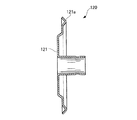
また、本実施の形態に係る可変容量型ターボチャージャ20においては、屈曲部51aの形状を略断面U字状に形成したものを適用したが、これに限らず、間隙部104におけるシール性を確保することができるものであれば何れの形状でもよく、例えば、図7に示すような略断面くの字状のビード構造を採用してもよい。   In addition, in the variable capacity turbocharger 20 according to the present embodiment, the bent portion 51a having a substantially U-shaped cross section is applied. However, the present invention is not limited to this, and sealing performance in the gap portion 104 is ensured. Any shape can be used as long as it can be performed. For example, a bead structure having a generally U-shaped cross section as shown in FIG. 7 may be adopted.

すなわち、図7に示すように、遮熱板120の底面部121の放射方向外端部に、周方向全周に亘って略断面くの字状の屈曲部121aを形成してもよい。この屈曲部121aは、タービンハウジング71側に向けて略断面くの字状に屈曲した形状をしており、上述の遮熱板50と同様、間隙部104に屈曲した状態で圧入されるようになっている(図4参照)。   That is, as shown in FIG. 7, a bent portion 121 a having a substantially cross-sectional shape may be formed on the radially outer end of the bottom surface portion 121 of the heat shield plate 120 over the entire circumference in the circumferential direction. The bent portion 121a is bent in a substantially cross-sectional shape toward the turbine housing 71 and is press-fitted into the gap portion 104 in a bent state similar to the heat shield plate 50 described above. (See FIG. 4).

このように、遮熱板120は、放射方向外端部に周方向全周に亘って形成された屈曲部121aが間隙部104に屈曲された状態で圧入されるので、遮熱板120のガタツキを防止でき、このガタツキに起因した遮熱板120の摩耗を防止できるとともに、遮熱板120の放射方向外端部の周方向全周に亘ってタービンハウジング71とベアリングハウジング41との間のシール性を向上させることができる。   Thus, the heat shield plate 120 is press-fitted in a state where the bent portion 121a formed on the outer circumferential end of the radial direction is bent in the gap portion 104. And the wear of the heat shield 120 due to the rattling can be prevented, and the seal between the turbine housing 71 and the bearing housing 41 over the entire circumference in the radial outer end of the heat shield 120. Can be improved.

また、屈曲部121aの弾性力によって遮熱板120がタービンハウジング71またはベアリングハウジング41の遮熱板対向面に密着させることができるので、水蒸気を含む高温の排気ガスにベアリングハウジング41が晒されるのを防止して、凝縮水の発生を抑制することができ、凝縮水の付着によるベアリングハウジング41の腐食を防止することができる。   Further, since the heat shield plate 120 can be brought into close contact with the heat shield plate facing surface of the turbine housing 71 or the bearing housing 41 by the elastic force of the bent portion 121a, the bearing housing 41 is exposed to high-temperature exhaust gas containing water vapor. Therefore, the generation of condensed water can be suppressed, and corrosion of the bearing housing 41 due to the adhesion of condensed water can be prevented.

また、本実施の形態においては、可変ノズル機構45を採用する可変容量型ターボチャージャ20に本発明を適用する例について説明したが、これに限らず、例えば可変ノズル機構を採用していないターボチャージャに本発明を適用するようにしてもよい。   In the present embodiment, the example in which the present invention is applied to the variable displacement turbocharger 20 that employs the variable nozzle mechanism 45 has been described. However, the present invention is not limited to this, and for example, a turbocharger that does not employ the variable nozzle mechanism. You may make it apply this invention to.

また、今回開示された実施の形態は、すべての点で例示であって、この実施の形態に制限されるものではない。本発明の範囲は、上記した実施の形態のみの説明ではなくて特許請求の範囲によって示され、特許請求の範囲と均等の意味および範囲内での全ての変更が含まれることが意図される。   In addition, the embodiment disclosed this time is illustrative in all respects, and is not limited to this embodiment. The scope of the present invention is shown not by the above description of the embodiments but by the scope of the claims, and is intended to include all modifications within the meaning and scope equivalent to the scope of the claims.

以上説明したように、本発明に係る可変容量型ターボチャージャは、遮熱板によるタービンハウジングとベアリングハウジングとの間のシール性を確保することができ、凝縮水の付着によるベアリングハウジングの腐食を防止することができるという効果を有し、内燃機関から排出される排気ガスの熱を遮熱する遮熱板を有するターボチャージャ全般に有用である。   As described above, the variable capacity turbocharger according to the present invention can ensure the sealing performance between the turbine housing and the bearing housing by the heat shield and prevent the corrosion of the bearing housing due to the adhering condensed water. The present invention is useful for all turbochargers having a heat shield plate that shields the heat of exhaust gas discharged from an internal combustion engine.

1…ディーゼルエンジン(内燃機関)、4a…吸気通路、8a…排気通路、20…可変容量型ターボチャージャ(ターボチャージャ)、41…ベアリングハウジング、41a、41b…フランジ部、41e…タービンハウジング側端面、50、120…遮熱板、51、121…底面部、51a、121a…屈曲部、52…側面部、62…回転軸、71…タービンハウジング、71b…ガス流路(排気ガス導入通路)、71d…内周端面、71e…フランジ部側内周面、73…タービンホイール、83…コンプレッサホイール、102…リンク室、104…間隙部   DESCRIPTION OF SYMBOLS 1 ... Diesel engine (internal combustion engine), 4a ... Intake passage, 8a ... Exhaust passage, 20 ... Variable displacement turbocharger (turbocharger), 41 ... Bearing housing, 41a, 41b ... Flange part, 41e ... End face on the turbine housing side 50, 120 ... heat shield plate, 51, 121 ... bottom face part, 51a, 121a ... bent part, 52 ... side part, 62 ... rotating shaft, 71 ... turbine housing, 71b ... gas flow path (exhaust gas introduction passage), 71d ... inner peripheral end surface, 71e ... flange side inner peripheral surface, 73 ... turbine wheel, 83 ... compressor wheel, 102 ... link chamber, 104 ... gap

Claims (1)

内燃機関の吸気通路上にコンプレッサホイールが配設されるとともに、前記コンプレッサホイールに回転軸を介して連結されるタービンホイールが前記内燃機関の排気通路上に配設されたターボチャージャであって、
前記回転軸を回転自在に支持するとともに外周部に周方向全周に亘って形成されたフランジ部を有し、前記回転軸を収容するベアリングハウジングと、
前記排気通路に連通する排気ガス導入通路を有するとともに、内周端面が前記フランジ部に取付けられ、内部に前記タービンホイールを収容するタービンハウジングと、
前記ベアリングハウジングと前記タービンハウジングの間に介装された円板状の遮熱板とを備え、
前記フランジ部の前記タービンハウジング側端面と前記タービンハウジングの前記フランジ部側内周面との間に、前記フランジ部の周方向全周に亘って間隙部が形成されたターボチャージャにおいて、
前記遮熱板が、前記遮熱板の放射方向外端部に周方向全周に亘って形成されるとともに、前記間隙部に屈曲された状態で圧入される屈曲部を有し、前記屈曲部の弾性力によって前記遮熱板が前記タービンハウジングまたは前記ベアリングハウジングの前記遮熱板対向面に密着することを特徴とするターボチャージャ。
A compressor wheel is disposed on an intake passage of the internal combustion engine, and a turbine wheel connected to the compressor wheel via a rotation shaft is a turbocharger disposed on the exhaust passage of the internal combustion engine,
A bearing housing that rotatably supports the rotating shaft and has a flange portion formed on the outer peripheral portion over the entire circumference, and accommodates the rotating shaft;
A turbine housing having an exhaust gas introduction passage communicating with the exhaust passage, an inner peripheral end face attached to the flange portion, and housing the turbine wheel therein;
A disk-shaped heat shield disposed between the bearing housing and the turbine housing;
In the turbocharger in which a gap portion is formed over the entire circumference in the circumferential direction of the flange portion between the turbine housing side end surface of the flange portion and the flange portion side inner peripheral surface of the turbine housing.
The heat shield plate has a bent portion that is formed in the radially outer end of the heat shield plate over the entire circumference and is press-fitted in a bent state in the gap portion, and the bent portion The turbocharger is characterized in that the heat shield plate comes into close contact with the heat shield plate facing surface of the turbine housing or the bearing housing by the elastic force of the turbocharger.
JP2012257474A 2012-11-26 2012-11-26 Turbocharger Pending JP2013047525A (en)

Priority Applications (1)

Application Number Priority Date Filing Date Title
JP2012257474A JP2013047525A (en) 2012-11-26 2012-11-26 Turbocharger

Applications Claiming Priority (1)

Application Number Priority Date Filing Date Title
JP2012257474A JP2013047525A (en) 2012-11-26 2012-11-26 Turbocharger

Related Parent Applications (1)

Application Number Title Priority Date Filing Date
JP2008318680A Division JP2010138885A (en) 2008-12-15 2008-12-15 Turbocharger

Publications (2)

Publication Number Publication Date
JP2013047525A true JP2013047525A (en) 2013-03-07
JP2013047525A5 JP2013047525A5 (en) 2013-05-02

Family

ID=48010613

Family Applications (1)

Application Number Title Priority Date Filing Date
JP2012257474A Pending JP2013047525A (en) 2012-11-26 2012-11-26 Turbocharger

Country Status (1)

Country Link
JP (1) JP2013047525A (en)

Cited By (2)

* Cited by examiner, † Cited by third party
Publication number Priority date Publication date Assignee Title
WO2018179328A1 (en) * 2017-03-31 2018-10-04 三菱重工エンジン&ターボチャージャ株式会社 Turbine housing and turbo charger provided with same
CN110520607A (en) * 2017-10-31 2019-11-29 三菱重工发动机和增压器株式会社 Turbine and turbocharger with the turbine

Citations (5)

* Cited by examiner, † Cited by third party
Publication number Priority date Publication date Assignee Title
JPS63150424A (en) * 1986-12-15 1988-06-23 Honda Motor Co Ltd Housing structure for turbocharger
JPS63158546U (en) * 1987-04-04 1988-10-18
JPH11229886A (en) * 1998-02-13 1999-08-24 Taiho Kogyo Co Ltd Turbocharger sealing unit
JP2001173450A (en) * 1999-12-20 2001-06-26 Mitsubishi Heavy Ind Ltd Variable turbocharger
JP2007231934A (en) * 2006-02-02 2007-09-13 Ihi Corp Turbocharger with variable nozzle

Patent Citations (5)

* Cited by examiner, † Cited by third party
Publication number Priority date Publication date Assignee Title
JPS63150424A (en) * 1986-12-15 1988-06-23 Honda Motor Co Ltd Housing structure for turbocharger
JPS63158546U (en) * 1987-04-04 1988-10-18
JPH11229886A (en) * 1998-02-13 1999-08-24 Taiho Kogyo Co Ltd Turbocharger sealing unit
JP2001173450A (en) * 1999-12-20 2001-06-26 Mitsubishi Heavy Ind Ltd Variable turbocharger
JP2007231934A (en) * 2006-02-02 2007-09-13 Ihi Corp Turbocharger with variable nozzle

Cited By (3)

* Cited by examiner, † Cited by third party
Publication number Priority date Publication date Assignee Title
WO2018179328A1 (en) * 2017-03-31 2018-10-04 三菱重工エンジン&ターボチャージャ株式会社 Turbine housing and turbo charger provided with same
US11506086B2 (en) 2017-03-31 2022-11-22 Mitsubishi Heavy Industries Engine & Turbocharger, Ltd. Turbine housing and turbo charger provided with same
CN110520607A (en) * 2017-10-31 2019-11-29 三菱重工发动机和增压器株式会社 Turbine and turbocharger with the turbine

Similar Documents

Publication Publication Date Title
JP2010138885A (en) Turbocharger
US8596063B2 (en) Exhaust treatment system for an internal combustion engine
CN107339168B (en) Engine system
US8196394B2 (en) Exhaust purification apparatus for engine
JP5763294B2 (en) Exhaust purification equipment
JP2010180863A (en) Exhaust pipe liquid injection system, exhaust emission control system, exhaust pipe liquid injection method and exhaust emission control method
JP2013142363A (en) Exhaust emission control device of diesel engine
JP2016148259A (en) Exhaust emission control device
JP5471650B2 (en) Turbocharger compressor housing
JP2009091984A (en) Exhaust emission control device
JP2010031769A (en) Exhaust emission control device
JP5020185B2 (en) Exhaust purification device
US11008982B2 (en) Exhaust-gas turbocharger
JP2009257090A (en) Variable capacity turbocharger
JP2013047525A (en) Turbocharger
JP2011236874A (en) Emission control device
US9982590B2 (en) Internal-combustion-engine supercharger
JP2008240552A (en) Exhaust emission control device for internal combustion engine
JP5032409B2 (en) Exhaust purification device
JP2016211486A (en) Exhaust emission control system
JP2010031719A (en) Exhaust emission control device
JP2010090875A (en) Exhaust gas control device for internal combustion engine
US8800267B2 (en) Control system for modulating an air mass
JP2012092746A (en) Exhaust emission control device
US20170074149A1 (en) Thermal management system for aftertreatment system

Legal Events

Date Code Title Description
A621 Written request for application examination

Free format text: JAPANESE INTERMEDIATE CODE: A621

Effective date: 20121126

A521 Written amendment

Free format text: JAPANESE INTERMEDIATE CODE: A523

Effective date: 20130313

A131 Notification of reasons for refusal

Free format text: JAPANESE INTERMEDIATE CODE: A131

Effective date: 20131112

A521 Written amendment

Free format text: JAPANESE INTERMEDIATE CODE: A523

Effective date: 20140108

A131 Notification of reasons for refusal

Free format text: JAPANESE INTERMEDIATE CODE: A131

Effective date: 20140401

A521 Written amendment

Free format text: JAPANESE INTERMEDIATE CODE: A523

Effective date: 20140528

A02 Decision of refusal

Free format text: JAPANESE INTERMEDIATE CODE: A02

Effective date: 20140701