JP2013046512A - Power supply device - Google Patents
Power supply device Download PDFInfo
- Publication number
- JP2013046512A JP2013046512A JP2011183551A JP2011183551A JP2013046512A JP 2013046512 A JP2013046512 A JP 2013046512A JP 2011183551 A JP2011183551 A JP 2011183551A JP 2011183551 A JP2011183551 A JP 2011183551A JP 2013046512 A JP2013046512 A JP 2013046512A
- Authority
- JP
- Japan
- Prior art keywords
- remaining capacity
- batteries
- power supply
- supply device
- battery
- Prior art date
- Legal status (The legal status is an assumption and is not a legal conclusion. Google has not performed a legal analysis and makes no representation as to the accuracy of the status listed.)
- Pending
Links
Images


Classifications
-
- Y—GENERAL TAGGING OF NEW TECHNOLOGICAL DEVELOPMENTS; GENERAL TAGGING OF CROSS-SECTIONAL TECHNOLOGIES SPANNING OVER SEVERAL SECTIONS OF THE IPC; TECHNICAL SUBJECTS COVERED BY FORMER USPC CROSS-REFERENCE ART COLLECTIONS [XRACs] AND DIGESTS
- Y02—TECHNOLOGIES OR APPLICATIONS FOR MITIGATION OR ADAPTATION AGAINST CLIMATE CHANGE
- Y02E—REDUCTION OF GREENHOUSE GAS [GHG] EMISSIONS, RELATED TO ENERGY GENERATION, TRANSMISSION OR DISTRIBUTION
- Y02E60/00—Enabling technologies; Technologies with a potential or indirect contribution to GHG emissions mitigation
- Y02E60/10—Energy storage using batteries
Abstract
Description
この発明は、各種の電気機器の電源として用いることができる電源装置に関する。 The present invention relates to a power supply device that can be used as a power supply for various electric devices.
近年、例えばねじ締め機や穴明け用の電気ドリル等の主として手持ち式の電動工具では、例えば100Vの交流電源を電源とするものに加えて、充電により繰り返し使用可能なリチウムイオンバッテリ(直流電源)を電源とする充電式電動工具が普及してきている。後者の充電式電動工具の場合には、前者の交流電源式の場合のような長い電源コードを電源コンセントに接続する必要がないので、特に屋外での高い作業性若しくは使い勝手を得ることができる。
また、充電式電動工具の場合、複数のバッテリを用意することにより、その一つを工具本体に取り付けて電源として使用する最中に、別の一つを別途用意した充電器で充電しておくことができ、これにより電動工具の長時間連続使用を実現して作業の効率化を図ることができる。但し、充電済みのバッテリに交換する手間があるため、従来これを補うために、複数のバッテリを並列に取り付けて大きな残容量を出力可能な電源装置が提供されている。例えば、下記の特許文献にはこの電源装置に関する技術が開示されている。この電源装置によれば、複数のバッテリについて並列接続と直列接続を併存させることにより電力の長時間出力と高出力化の双方を実現することができ、各バッテリの残容量の適切な制御により出力の効率化を図ることができる。
In recent years, for example, mainly hand-held power tools such as screwing machines and drilling electric drills, for example, a lithium-ion battery (DC power supply) that can be repeatedly used by charging in addition to a 100 V AC power supply. Rechargeable electric tools that use a power source are becoming popular. In the case of the latter rechargeable electric tool, since it is not necessary to connect a long power cord to the power outlet as in the case of the former AC power supply type, particularly high workability or usability outdoors can be obtained.
In the case of a rechargeable electric tool, by preparing a plurality of batteries, one of them is attached to the tool body and used as a power source, and another one is charged with a separately prepared charger. As a result, the electric tool can be used continuously for a long time, and the work efficiency can be improved. However, since there is a trouble of replacing the charged battery, a power supply device that can output a large remaining capacity by attaching a plurality of batteries in parallel has been provided. For example, the following patent document discloses a technique related to the power supply device. According to this power supply device, it is possible to realize both long-time output of power and high output by coexisting parallel connection and series connection for a plurality of batteries, and output by appropriate control of the remaining capacity of each battery. Can be made more efficient.
しかしながら、上記従来の電源装置によれば、並列及び直列に接続した複数のバッテリの合計の残容量については発光ダイオード等の表示部により表示されるものの、各バッテリ個別の残容量について表示がなされおらず、この点で当該電源装置の使い勝手を改善する必要があった。
本発明は、複数のバッテリを取り付けてその合計の電力を出力可能な電源装置において、取り付けた複数のバッテリ全体の合計残容量と各バッテリの個別の残容量の双方が表示されるようにすることを目的とする。
However, according to the above-described conventional power supply device, although the total remaining capacity of a plurality of batteries connected in parallel and in series is displayed by a display unit such as a light emitting diode, the remaining capacity of each battery is not displayed. However, it was necessary to improve the usability of the power supply device in this respect.
According to the present invention, in a power supply device capable of attaching a plurality of batteries and outputting the total power, both the total remaining capacity of the plurality of attached batteries and the individual remaining capacity of each battery are displayed. With the goal.
上記の課題は、下記の発明によって解決される。
第1の発明は、複数のバッテリを取り付けて、合計の電力を電源として出力可能な電源装置であって、複数のバッテリの合計の残容量を報知する合計残容量報知機能と、複数のバッテリの各々の残容量を個別に報知する個別残容量報知機能の双方を備えた電源装置である。
第1の発明によれば、取り付けたバッテリの合計の残容量と、個々のバッテリの残容量の双方が報知されることにより、当該電源装置の使い勝手を従来よりも改善することができる。報知の形態には、目で見て(目視により)確認できる表示、メロディや音声等の音による報知手段を用いることができる。
第2の発明は、第1の発明において、合計残量報知機能と個別残容量報知機能の双方について、目視により確認できる表示を用いた電源装置である。
第2の発明によれば、取り付けたバッテリの個々の残容量と合計残容量の双方を目で見て迅速且つ直感的に確認することができ、この点で当該電源装置の使い勝手を一層高めることができる。
第3の発明は、第2の発明において、表示を外部から確認可能な電源装置である。
第3の発明によれば、わざわざ蓋を開ける等の操作をすることなく残容量を迅速に確認することができる。
第4の発明は、第1〜第3の何れか一つの発明において、合計残容量報知機能による報知がスイッチ操作によりなされる電源装置である。
第4の発明によれば、スイッチ操作により必要な時にのみ合計残容量が報知されることから、常時報知する構成に比して消費電力を節約することができる。
The above problems are solved by the following invention.
A first invention is a power supply device capable of attaching a plurality of batteries and outputting the total power as a power source, the total remaining capacity notifying function for notifying the total remaining capacity of the plurality of batteries, and the plurality of batteries It is a power supply device provided with both the individual remaining capacity alerting | reporting functions which alert | report each remaining capacity separately.
According to the first invention, both the total remaining capacity of the attached batteries and the remaining capacity of each battery are notified, so that the usability of the power supply device can be improved as compared with the conventional one. As a form of notification, a display that can be visually confirmed (visually), or a notification means by sound such as melody or voice can be used.
2nd invention is a power supply device using the display which can confirm visually about both of a total remaining amount alerting | reporting function and an individual remaining capacity alerting | reporting function in 1st invention.
According to the second invention, both the individual remaining capacity and the total remaining capacity of the attached battery can be visually confirmed quickly and intuitively. In this respect, the usability of the power supply device is further enhanced. Can do.
A third invention is the power supply device according to the second invention, wherein the display can be confirmed from the outside.
According to the third aspect of the present invention, the remaining capacity can be quickly confirmed without performing an operation such as opening the lid.
A fourth invention is the power supply apparatus according to any one of the first to third inventions, wherein the notification by the total remaining capacity notification function is made by a switch operation.
According to the fourth invention, since the total remaining capacity is notified only when necessary by the switch operation, it is possible to save power consumption as compared with the configuration in which notification is always made.
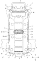
次に、本発明の実施形態を図1〜図6に基づいて説明する。図1は、本実施形態の電源装置1を示している。この電源装置1は、4つのバッテリ11〜14を取り付けた本体部10と、この本体部10の正面側であって4つのバッテリ11〜14を覆う蓋部2を備えている。蓋部2は、ヒンジ部3を介して本体部10の上部に上下に回動可能に支持されている。蓋部2はヒンジ部3を中心にして上方へ回動させれば開くことができ、下方へ回動させれば閉じることができる。蓋部2の閉じ位置は、当該蓋部2の下部に設けたロックレバー4を本体部10の下部に設けた引き掛け爪5に引き掛けておくことによりロックされる。ロックレバー4は圧縮ばね6によってロック側に付勢されている。
本体部10と蓋部2の下面側には、合計4箇所の脚部7〜7が設けられている。この脚部7〜7によって、当該電源装置1を上方へ立てた自立状態(縦置き状態)に設置できる。また、本体部10の上部には持ち運び用のキャリングハンドル8が設けられている。このキャリングハンドル8は、ヒンジ部3を中心にして上下に回動可能に設けられている。このキャリングハンドル8は、上方へ起立させて使用者が把持することができ、下方へ傾倒させて収納しておくことができる。図2は、キャリングハンドル8を下方へ傾倒させて収納した状態を示し、図3は上方へ起立させた状態を示している。
本体部10の背面四隅には、横置き用の脚部9〜9が設けられている。この脚部9〜9を接地させて当該電源装置1は横置き姿勢に設置することもできる。
Next, an embodiment of the present invention will be described with reference to FIGS. FIG. 1 shows a
A total of four
At the four corners of the back surface of the
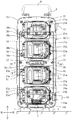
図3は、蓋部2を開放若しくは取り外した状態を示している。このため、図3では本体部10の正面が見えている。本体部10の正面に、何れもスライド取り付け形式の4つのバッテリ11〜14が上下に並列状態に取り付けられている。以下の説明では、上側から第1バッテリ11、第2バッテリ12、第3バッテリ13、第4バッテリ14とも称する。第1〜第4バッテリ11〜14は、例えば図6に示す充電式の電気カンナ50等の電動工具の電源として用いられるもので、本実施形態では4つとも同じく18V仕様のリチウムイオンバッテリが用いられている。各バッテリ11〜14は、バッテリケース11a(12a,13a,14a)内に、複数本のバッテリセル11b〜11bを収容したもので、別途充電器で充電することにより繰り返し使用することができる(二次電池)。この各バッテリ11〜14自体については既に公知のものをそのまま用いることができる。各バッテリ11〜14の側部には、工具本体の後部に設けたバッテリ取り付け部51に対する取り付け状態をロックするためのロック爪11c〜14cが設けられている。
FIG. 3 shows a state where the
本体部10の正面に、この4つのバッテリ11〜14を取り付けるためのバッテリ取り付け部21〜24が上下方向に4箇所並列状態で配置されている。本体部10は正面側に開放する箱体形状の本体ケース15と、この本体ケース15の開口部に沿ってねじ止めした台座部16を備えている。台座部16に4つのバッテリ取り付け部21〜24が取り付けられている。各バッテリ取り付け部21〜24は、上記充電式電気カンナ50(電動工具)のバッテリ取り付け部51と同様のスライド取り付け構造で、4箇所とも同じスライド取り付け構造を有している。各バッテリ取り付け部21〜24には、上下一対のスライドレール21a,21a〜24a,24aが設けられている。各スライドレール21a,21a〜24a,24a間には、コネクタ接続部21b〜24bが配置されている。図3において、各バッテリ11〜14を各バッテリ取り付け部21〜24に対して、左側から右側へ横方向にスライドさせることにより各バッテリ11〜14を取り付けることができ、逆に右側から左側へ横方向にスライドさせることにより各バッテリ11〜14をバッテリ取り付け部21〜24から取り外すことができる。各バッテリ11〜14を各バッテリ取り付け部21〜24に取り付けると、各コネクタ接続部21b〜24bを介して各バッテリ11〜14が電気的に接続される。4つのバッテリ11〜14は、それぞれ個別に取り付け、取り外しすることができる。各バッテリ11〜14のロック爪11c〜14cをばね付勢力に抗して指先でアンロック操作するとロックが解除されて取り外すことができる。
この第1〜第4バッテリ11〜14は、何れも全てのバッテリ取り付け部21〜24に対して取り付けの互換性を有している。取り付けた第1〜第4のバッテリ11〜14は、その2つが並列接続されて長時間出力が実現され、並列接続された二組が相互に直列接続されて36V出力が実現される。
Each of the first to
本実施形態の電源装置1は、取り付けたバッテリ11〜14の残容量を示す残容量報知機能Zを備えている。この残容量報知機能Zは、各バッテリ11〜14の個別の残容量Zeを報知する個別残容量報知部30〜30と、4つのバッテリ11〜14の合計の残容量Ztを報知する全体残容量報知部31により達成される。
図3に示すように前者の個別残容量報知部30〜30は、各バッテリ取り付け部21〜24の左側に配置されている。各個別残容量報知部30は、台座部16に取り付けた2個のインジケータランプ30a,30aを備えている。それぞれ2つのインジケータランプ30a,30aが以下のように点灯若しくは点滅することにより対応する第1〜第4バッテリ11〜14の個別残容量Zeが個別に報知される。
各個別残容量報知部30において、インジケータランプ30a,30aが2つとも緑色に点灯することにより、バッテリ11〜14の個別残容量Zeが十分な満充電状態が報知される。一方が緑色で他方が赤色に点灯した状態では、個別残容量Zeが少ない状態が報知される。2つとも赤色に点灯した状態では、個別残容量Zeが不足して電源供給できない状態(要充電状態)が報知される。また、インジケータランプ30a,30aが2つとも赤色に点滅した状態では、バッテリ11〜14の温度や電流値に関するエラー状態が報知される。
The
As shown in FIG. 3, the former individual remaining capacity notification units 30 to 30 are arranged on the left side of the
In each individual remaining capacity notification unit 30, when both
後者の全体残容量報知部31は、本体部10の正面ほぼ中央に配置されている。この全体残容量報知部31は、本体部10の正面ほぼ中央であって台座部16の上下左右ほぼ中央に設けた断面長円形の支持筒部32の上面に設けられている。この全体残容量報知部31及び支持筒部32は、上から2つ目の第2バッテリ12と上から三つ目の第3バッテリ13との間であって、本体部10の上下方向及び左右幅方向のほぼ中央に設けられている。
この全体残容量報知部31は、図示するように5つのインジケータランプ35〜35と一つの操作スイッチ36を備えている。4つのバッテリ11〜14の合計残容量Ztが多いほど赤色に点灯するインジケータランプ35〜35の個数が多くなる。インジケータランプ35〜35が5つとも赤色に点灯することにより、バッテリ11〜14の合計残容量Ztが十分であることが報知される。インジケータランプ35〜35の点灯個数が少なくなることにより、バッテリ11〜14の合計残容量Ztが少なくなっていることが報知される。4つのバッテリ11〜14の全ての個別残容量Zeがなくなると合計残容量Ztもなくなるので、インジケータランプ35〜35は5つとも点灯しない状態となる。
このことから、例えば4つ若しくは全てのインジケータランプ35〜35が点灯することにより合計残容量Ztが十分である場合であっても、個別残容量報知部30〜30を確認することにより何れかのバッテリ11(又は12,13,14)の個別残容量Zeが不足している場合(インジケータランプ30a,30aの一方又は双方が赤色に点灯している場合)があり、これにより充電が必要なバッテリ11(又は12,13,14)を確実に特定することができる。
The latter total remaining
The total remaining
From this, for example, even if the total remaining capacity Zt is sufficient when four or all the
本実施形態では、インジケータランプ35〜35が点灯するか否かは、操作スイッチ36を押し操作した状態でのみ確認できるようになっている。このため、仮に全体残容量Ztが不足する場合であっても操作スイッチ36を押し操作しない状態ではインジケータランプ35〜35は点灯しない。操作スイッチ36を押し操作すると、全体残容量Ztが不足する場合に一部若しくは全てのインジケータランプ35〜35が点灯しない状態となり、これにより使用者は第1〜第4バッテリ11〜14の合計残容量Ztが不足していることを確認することができる。操作スイッチ36を押し操作した時点で全てのインジケータランプ35〜35が点灯することにより第1〜第4バッテリ11〜14の合計残容量Ztが十分であることを確認することができる。
このように、必要時のみ操作スイッチ36を押し操作してインジケータランプ35〜35を点灯させる構成であるので消費電力を節約することができる。
本実施形態の電源装置1では、蓋部2を閉じた状態でも外部からこの全体残容量報知部31を目で確認することができるようになっている。蓋部2のほぼ中央には、全体残容量報知部31の長円形と相似形をなす長円形の窓部2aが設けられている。本体部10に対して蓋部2を閉じると、この窓部2a内に全体残容量報知部31が進入して塞がれた状態となる。これにより、蓋部2を閉じた状態でこの全体残容量報知部31を外部から目で見て確認できるようになっている。
前記したように第1〜第4バッテリ11〜14は、電気的にその2つが並列接続され、並列接続された二組が相互に直列接続されている。このため、本実施形態の電源装置1は、全てのバッテリ取り付け部21〜24にバッテリ11〜14を取り付けた状態だけでなく、少なくとも2箇所のバッテリ取り付け部21,22(又は23,24又は21,23又は22,24又は21,24)にバッテリ11〜14を一つずつ取り付けることにより少なくとも直列接続が成立するよう制御され、これにより36V電力が確実に出力されるようになっている。
In the present embodiment, whether or not the
As described above, since the
In the
As described above, the first to
図2に示すように、本体部10内には、取り付けた第1〜第4バッテリ11〜14及びバッテリ取り付け部21〜24、さらには残容量表示機能Zを電気的に制御するための制御回路と直流36V電力を出力するための電源回路を含む制御基板40が配置されている。この制御基板40はその全体(表裏両面)を樹脂でモールドされた状態で台座部16の背面側に沿って固定されている。
本体部10の右側部下側からは、直流36V電源供給用の電源コード41が引き出されている。この電源コード41を経て外部機器に電力を供給することができる。図1において、二点鎖線で示すように、この電源コード41の引き出し位置は、本体部10の左側部に変更することができる。いずれか一方の引き出し位置を任意に選択して電源コード41の取り回しを容易にすることにより当該電源装置1の使い勝手を良くすることができる。
また、本体部10の右側部には、メインスイッチ42が設けられている。このメインスイッチ42をオン操作することにより、電源コード41を経て電力供給可能な状態となる。メインスイッチ42をオフ操作した状態では電源回路が遮断されて、電力供給されない状態となり、これにより無駄な待機電力の消費が抑制されるようになっている。
図1及び図2に示すように本体部10の背面には、背負い用のベルト(背負いベルト43)を取り付けることができる。この背負いベルト43は、横置き用の脚部9〜9を利用して本体部10の背面に沿って取り付けることができる。脚部9〜9は、ねじ部の締め込みにより取り付ける構成のもので、これを一旦外して背負いベルト43を本体部10の背面に共締めすることにより当該背負いベルト43を取り付けることができる。使用者は、この背負いベルト43を用いて当該電源装置1を背負って携帯することができる。
As shown in FIG. 2, a control circuit for electrically controlling the attached first to
A
A
As shown in FIGS. 1 and 2, a backpack belt (backpack belt 43) can be attached to the back surface of the
以上のように構成した本実施形態の電源装置1によれば、充電式電気カンナ50等の電動工具の電源として用いられるバッテリ11〜14を4つ取り付けて、その合計電力(36V)を長時間にわたって出力することができる。このため、特に屋外において交流電源を利用できないような作業環境であっても効率よく作業を行うことができる。
また、電源装置1は、第1〜第4バッテリ11〜14の残容量報知機能Zを備えている。この残容量報知機能Zは、第1〜第4バッテリ11〜14の個別の残容量Zeを報知する個別残容量報知部30に加えて、本体部10に取り付けた第1〜第4バッテリ11〜14の全て若しくは一部の合計の残容量Ztを報知する全体残容量報知部31を備えている。このため、第1〜第4バッテリ11〜14の個々の残容量Zeだけでなく、当該電源装置1の全体としての出力可能な残容量Ztを確認して、当該電源装置1の運用を効率よく行うことができる。特に、例示した実施形態によれば、第1〜第4バッテリ11〜14の個々の残容量Zeを個別残容量報知部30のインジケータランプ30a〜30aにより目で見て確認できる他、全体の残容量Ztについても全体残容量報知部31のインジケータランプ35〜35により一目で確認することができるので、夜間等の暗所であっても離れた場所から瞬時に確認することができ、この点で当該電源装置1の使い勝手を高めることができる。
また、全体残容量報知部31のインジケータランプ35〜35は、蓋部2を閉じた状態であっても窓部2aを経て外部から目視することできる。このため、蓋部2をわざわざ開放しなくとも、第1〜第4バッテリ11〜14の全体残容量Ztを離れた場所から瞬時確認することができ、この点でも当該残容量報知機能の取り扱い性が一層高められている。
さらに、全体残容量報知部31の操作スイッチ36についても、蓋部2を閉じた状態で窓部2aを経て外部から操作可能となっている。全体残容量報知部31は、この操作スイッチ36をオン操作した状態でのみインジケータランプ35〜35を点灯させる等して報知機能を発揮する構成となっている。このため、操作スイッチ36をオン操作しない状態では残容量Ztが不足する状態であってもインジケータランプ35〜35は点灯せず、これにより待機電力等の不必要時の無駄な電力消費をなくすことができるので、常時報知する構成に比してバッテリ11〜14を長持ちさせることができる。
According to the
Moreover, the
In addition, the
Further, the
以上説明した実施形態には種々変更を加えることができる。例えば、4つのバッテリ11〜14を取り付け可能な電源装置1を例示したが、取り付け可能な複数のバッテリの個数については任意に設定することができる。なお、前記したように本体部10に設定したバッテリ取り付け部21〜24の全てにバッテリ11〜14を取り付けた状態の他、一部のバッテリ取り付け部についてバッテリを取り付けない状態であっても取り付けたバッテリについて当該電源装置1を用いることができ、残容量報知機能Zを取り付けたバッテリについて同等に機能させることができる。
また、本体部10の正面ほぼ中央であって、第2バッテリ12と第3バッテリ13との間に全体残容量報知部31を設けた構成を例示したが、例えば本体部10の側部あるいは蓋部2に設ける構成としてもよい。
さらに、全体残容量報知部31に操作スイッチ36を設けて、この操作スイッチ36をオン操作した状態でのみ報知する構成を例示したが、係る操作スイッチ36を省略して常時報知する構成としてもよい。
また、全体残容量報知部31に5つのインジケータランプ35〜35を設けた構成を例示したが、インジケータランプの個数については変更して実施することができる。例えば、一つのインジケータランプであってもその点灯色を変化させたり、点滅させ、その点滅の間隔を変化させることによっても全体残容量Ztの変化を報知させることができる。
また、インジケータランプに代えて残容量を数値表示(デジタル表示)する構成としてもよい。
蓋部2の窓部2aを省略して、蓋部2を開放して全体残容量報知部31を目視により確認する構成としてもよい。
また、個別残容量報知部30のインジケータランプ30a〜30a及び全体残容量報知部31のインジケータランプ35〜35を目で見る(目視により)ことにより、個別残容量Ze及び全体残容量Ztが報知される構成を例示したが、これらの報知手段としては目視に限らず、ブザーやメロディ等の音あるいは音声や振動等によって報知する構成としてもよい。
また、メインスイッチ42は省略して、バッテリをバッテリ取り付け部に取り付けた時点で、電源を出力可能な状態となるよう構成してもよい。
さらに、電源コード41により直流36V電源を出力する構成を例示したが、昇圧回路等を用いることによりさらに高い電圧の電力を出力する構成としてもよい。また、直流電源ではなく交流電源を出力する構成、あるいはその双方を出力する構成としてもよい。
Various modifications can be made to the embodiment described above. For example, although the
Further, the configuration in which the entire remaining
Furthermore, the
Moreover, although the structure which provided the five indicator lamps 35-35 in the total remaining capacity alerting | reporting
Further, the remaining capacity may be displayed numerically (digitally) instead of the indicator lamp.
It is good also as a structure which abbreviate | omits the
Further, by visually observing (visually) the
Further, the
Furthermore, although a configuration in which a DC 36V power supply is output by the
1…電源装置
2…蓋部、2a…窓部
3…ヒンジ部
4…ロックレバー
5…引き掛け爪
6…圧縮ばね
7…脚部(縦置き用)
8…キャリングハンドル
9…脚部(横置き用)
10…本体部
11…第1バッテリ
11a…バッテリケース、11b…バッテリセル、11c…ロック爪
12…第2バッテリ
12a…バッテリケース、12b…バッテリセル、12c…ロック爪
13…第3バッテリ
13a…バッテリケース、13b…バッテリセル、13c…ロック爪
14…第4バッテリ
14a…バッテリケース、14b…バッテリセル、14c…ロック爪
15…本体ケース
16…台座部
21〜24…バッテリ取り付け部
21a〜24a…スライドレール
21b〜24b…コネクタ接続部
Z…残容量報知機能
Ze…個別残容量
Zt…全体残容量(合計残容量)
30…個別残容量報知部、30a…インジケータランプ
31…全体残容量報知部
32…支持筒部
35…インジケータランプ
36…操作スイッチ
40…制御基板
41…電源コード
42…メインスイッチ
43…背負いベルト
50…充電式電気カンナ
51…バッテリ取り付け部
DESCRIPTION OF
8 ... Carrying
DESCRIPTION OF
DESCRIPTION OF SYMBOLS 30 ... Individual remaining capacity notification part, 30a ...
Claims (4)
The power supply device according to any one of claims 1 to 3, wherein notification by the total remaining capacity notification function is performed by a switch operation.
Priority Applications (4)
| Application Number | Priority Date | Filing Date | Title |
|---|---|---|---|
| JP2011183551A JP2013046512A (en) | 2011-08-25 | 2011-08-25 | Power supply device |
| DE212012000160.3U DE212012000160U1 (en) | 2011-08-25 | 2012-08-09 | Power supply apparatus |
| PCT/JP2012/070358 WO2013027599A1 (en) | 2011-08-25 | 2012-08-09 | Power supply apparatus |
| CN201290000772.XU CN204045695U (en) | 2011-08-25 | 2012-08-09 | Supply unit |
Applications Claiming Priority (1)
| Application Number | Priority Date | Filing Date | Title |
|---|---|---|---|
| JP2011183551A JP2013046512A (en) | 2011-08-25 | 2011-08-25 | Power supply device |
Related Child Applications (1)
| Application Number | Title | Priority Date | Filing Date |
|---|---|---|---|
| JP2014228648A Division JP5718518B2 (en) | 2014-11-11 | 2014-11-11 | Power supply |
Publications (2)
| Publication Number | Publication Date |
|---|---|
| JP2013046512A true JP2013046512A (en) | 2013-03-04 |
| JP2013046512A5 JP2013046512A5 (en) | 2013-08-29 |
Family
ID=48009989
Family Applications (1)
| Application Number | Title | Priority Date | Filing Date |
|---|---|---|---|
| JP2011183551A Pending JP2013046512A (en) | 2011-08-25 | 2011-08-25 | Power supply device |
Country Status (1)
| Country | Link |
|---|---|
| JP (1) | JP2013046512A (en) |
Cited By (5)
| Publication number | Priority date | Publication date | Assignee | Title |
|---|---|---|---|---|
| JP2014038727A (en) * | 2012-08-13 | 2014-02-27 | Hitachi Koki Co Ltd | Backpack type power source |
| JP2017093250A (en) * | 2015-11-17 | 2017-05-25 | オムロン株式会社 | Battery residual quantity display device, battery system and battery residual quantity display method |
| US10684328B2 (en) | 2015-12-01 | 2020-06-16 | Omron Corporation | Remaining battery charge estimation system and remaining battery charge estimation method |
| US10749430B2 (en) | 2015-03-13 | 2020-08-18 | Positec Power Tools (Suzhou) Co., Ltd. | Power transmission apparatus and control method therefor, and power supply system |
| CN112670640A (en) * | 2020-12-17 | 2021-04-16 | 湖南久森新能源有限公司 | Lithium ion battery with good heat dissipation effect |
Citations (11)
| Publication number | Priority date | Publication date | Assignee | Title |
|---|---|---|---|---|
| JPH01156765U (en) * | 1988-04-19 | 1989-10-27 | ||
| JPH0864003A (en) * | 1994-08-05 | 1996-03-08 | Hitachi Kaa Eng:Kk | Portable illumination tool |
| JPH08236970A (en) * | 1995-02-23 | 1996-09-13 | Sansha Electric Mfg Co Ltd | Portable power unit |
| JPH1116403A (en) * | 1997-06-26 | 1999-01-22 | Nippon Seimitsu Denki Kk | Floodlight |
| JP2000244146A (en) * | 1999-02-17 | 2000-09-08 | Sony Corp | Computer system and display |
| JP2002295200A (en) * | 2001-03-30 | 2002-10-09 | Railway Technical Res Inst | Method and device for marking on building |
| JP2003092837A (en) * | 2001-09-19 | 2003-03-28 | Matsushita Electric Ind Co Ltd | Portable power unit |
| JP2005056801A (en) * | 2003-08-07 | 2005-03-03 | Kayaba Ind Co Ltd | Floodlight |
| JP3110300U (en) * | 2005-02-09 | 2005-06-16 | 株式会社バンテック | Portable fuel cell device |
| JP2011097766A (en) * | 2009-10-30 | 2011-05-12 | Makita Corp | Power-supply device |
| JP2011159633A (en) * | 2008-06-19 | 2011-08-18 | Hitachi Ltd | Battery module, battery box, and railway vehicle equipped with the battery box |
-
2011
- 2011-08-25 JP JP2011183551A patent/JP2013046512A/en active Pending
Patent Citations (11)
| Publication number | Priority date | Publication date | Assignee | Title |
|---|---|---|---|---|
| JPH01156765U (en) * | 1988-04-19 | 1989-10-27 | ||
| JPH0864003A (en) * | 1994-08-05 | 1996-03-08 | Hitachi Kaa Eng:Kk | Portable illumination tool |
| JPH08236970A (en) * | 1995-02-23 | 1996-09-13 | Sansha Electric Mfg Co Ltd | Portable power unit |
| JPH1116403A (en) * | 1997-06-26 | 1999-01-22 | Nippon Seimitsu Denki Kk | Floodlight |
| JP2000244146A (en) * | 1999-02-17 | 2000-09-08 | Sony Corp | Computer system and display |
| JP2002295200A (en) * | 2001-03-30 | 2002-10-09 | Railway Technical Res Inst | Method and device for marking on building |
| JP2003092837A (en) * | 2001-09-19 | 2003-03-28 | Matsushita Electric Ind Co Ltd | Portable power unit |
| JP2005056801A (en) * | 2003-08-07 | 2005-03-03 | Kayaba Ind Co Ltd | Floodlight |
| JP3110300U (en) * | 2005-02-09 | 2005-06-16 | 株式会社バンテック | Portable fuel cell device |
| JP2011159633A (en) * | 2008-06-19 | 2011-08-18 | Hitachi Ltd | Battery module, battery box, and railway vehicle equipped with the battery box |
| JP2011097766A (en) * | 2009-10-30 | 2011-05-12 | Makita Corp | Power-supply device |
Cited By (9)
| Publication number | Priority date | Publication date | Assignee | Title |
|---|---|---|---|---|
| JP2014038727A (en) * | 2012-08-13 | 2014-02-27 | Hitachi Koki Co Ltd | Backpack type power source |
| US10749430B2 (en) | 2015-03-13 | 2020-08-18 | Positec Power Tools (Suzhou) Co., Ltd. | Power transmission apparatus and control method therefor, and power supply system |
| US11601002B2 (en) | 2015-03-13 | 2023-03-07 | Positec Power Tools (Suzhou) Co., Ltd. | Electrical energy transmission apparatus, method for controlling same, and power supply system |
| JP2017093250A (en) * | 2015-11-17 | 2017-05-25 | オムロン株式会社 | Battery residual quantity display device, battery system and battery residual quantity display method |
| WO2017086168A1 (en) * | 2015-11-17 | 2017-05-26 | オムロン株式会社 | Remaining battery capacity display device, battery system and remaining battery capacity display method |
| US10518640B2 (en) | 2015-11-17 | 2019-12-31 | Omron Corporation | Battery remaining capacity display device, battery system, and battery remaining capacity display method |
| US10684328B2 (en) | 2015-12-01 | 2020-06-16 | Omron Corporation | Remaining battery charge estimation system and remaining battery charge estimation method |
| CN112670640A (en) * | 2020-12-17 | 2021-04-16 | 湖南久森新能源有限公司 | Lithium ion battery with good heat dissipation effect |
| CN112670640B (en) * | 2020-12-17 | 2022-08-12 | 湖南久森新能源有限公司 | Lithium ion battery with good heat dissipation effect |
Similar Documents
| Publication | Publication Date | Title |
|---|---|---|
| EP2437328B1 (en) | Battery devices for power tools | |
| US9899853B2 (en) | AC power supply | |
| US10090498B2 (en) | Modular battery pack apparatus, systems, and methods including viral data and/or code transfer | |
| US9273857B2 (en) | Electrical component including tool and battery charger ports | |
| WO2016146045A1 (en) | Electrical energy provision device | |
| JP2013046512A (en) | Power supply device | |
| CN204045695U (en) | Supply unit | |
| JP5851156B2 (en) | Power supply | |
| AU2006202103A1 (en) | A device for electrical power supply to a power tool | |
| US20140043780A1 (en) | Hybrid portable power supply | |
| CN115663817A (en) | Electric energy transmission device, control method thereof and power supply system | |
| JP3171131U (en) | Mobile battery with uninterrupted power supply function | |
| CN202076827U (en) | Low-voltage power distribution cabinet | |
| KR20120000788U (en) | Portable dc/ac power supply unit | |
| JP6692177B2 (en) | Emergency power supply | |
| JP2006204079A (en) | Portable detachable multi-operating equipment set for measures against emergency/disaster | |
| JP2014147355A (en) | Electric bush cutter | |
| JP2007015032A (en) | Storing case with power tool and power tool system | |
| US9302339B2 (en) | Hybrid welder with detachable energy storage device | |
| JP5718518B2 (en) | Power supply | |
| EP2712769A1 (en) | Electrical power distribution module for a utility vehicle | |
| KR20160062888A (en) | Power supplying device for outdoor | |
| JP3231992U (en) | Mobile battery charger | |
| JP6324245B2 (en) | Power storage device | |
| AU2018102216A4 (en) | Cable distribution terminal block |
Legal Events
| Date | Code | Title | Description |
|---|---|---|---|
| A521 | Written amendment |
Free format text: JAPANESE INTERMEDIATE CODE: A523 Effective date: 20130710 |
|
| A621 | Written request for application examination |
Free format text: JAPANESE INTERMEDIATE CODE: A621 Effective date: 20130710 |
|
| A131 | Notification of reasons for refusal |
Free format text: JAPANESE INTERMEDIATE CODE: A131 Effective date: 20140520 |
|
| A521 | Written amendment |
Free format text: JAPANESE INTERMEDIATE CODE: A523 Effective date: 20140716 |
|
| A02 | Decision of refusal |
Free format text: JAPANESE INTERMEDIATE CODE: A02 Effective date: 20140812 |