JP2013032065A - Structure for mounting electric storage device - Google Patents
Structure for mounting electric storage device Download PDFInfo
- Publication number
- JP2013032065A JP2013032065A JP2011168393A JP2011168393A JP2013032065A JP 2013032065 A JP2013032065 A JP 2013032065A JP 2011168393 A JP2011168393 A JP 2011168393A JP 2011168393 A JP2011168393 A JP 2011168393A JP 2013032065 A JP2013032065 A JP 2013032065A
- Authority
- JP
- Japan
- Prior art keywords
- storage device
- power storage
- battery
- electric storage
- vehicle
- Prior art date
- Legal status (The legal status is an assumption and is not a legal conclusion. Google has not performed a legal analysis and makes no representation as to the accuracy of the status listed.)
- Granted
Links
Images


Landscapes
- Arrangement Or Mounting Of Propulsion Units For Vehicles (AREA)
Abstract
Description
本発明は、蓄電装置が搭載される構造に関するものである。 The present invention relates to a structure in which a power storage device is mounted.
組電池をプレートに搭載するとき、プレートの一部を曲げ加工によって組電池の側に突出させておき、この突出部分の先端に組電池を固定することがある。突出部分の先端に組電池を固定することにより、組電池の周囲にスペースを形成することができる。このスペースは、組電池の冷却に用いられる空気を移動させるスペースとして用いることができる。 When the assembled battery is mounted on the plate, a part of the plate may be projected to the assembled battery side by bending, and the assembled battery may be fixed to the tip of the protruding portion. A space can be formed around the assembled battery by fixing the assembled battery to the tip of the protruding portion. This space can be used as a space for moving air used for cooling the assembled battery.
上述した組電池の搭載構造において、組電池に外力が作用すると、プレートの突出部分が変形してしまうことがある。突出部分の先端には、組電池が固定されているため、突出部分が変形することによって、組電池の固定部分にも過度の負荷がかかってしまうおそれがある。 In the assembled battery mounting structure described above, when an external force acts on the assembled battery, the protruding portion of the plate may be deformed. Since the assembled battery is fixed to the tip of the protruding portion, an excessive load may be applied to the fixed portion of the assembled battery when the protruding portion is deformed.
本発明である蓄電装置の搭載構造は、充放電を行う蓄電装置と、蓄電装置が搭載される搭載プレートと、を有する。搭載プレートは、プレート本体と、支持部と、突起部とを有する。支持部は、曲げ加工によってプレート本体から蓄電装置の側に突出しており、支持部の先端には、蓄電装置が固定されている。突起部は、蓄電装置が位置する側において、プレート本体および支持部にまたがって設けられており、プレート本体および支持部から突出する。 The power storage device mounting structure according to the present invention includes a power storage device that performs charging and discharging, and a mounting plate on which the power storage device is mounted. The mounting plate has a plate main body, a support part, and a protrusion part. The support part protrudes from the plate body to the power storage device side by bending, and the power storage device is fixed to the tip of the support part. The protrusion is provided across the plate body and the support portion on the side where the power storage device is located, and protrudes from the plate body and the support portion.
本発明によれば、突起部を設けることにより、支持部の強度を向上させることができ、外力による支持部の変形を抑制することができる。支持部の先端には、蓄電装置が固定されているため、支持部の変形を抑制することにより、支持部の変形に伴って支持部および蓄電装置の固定部分に過度の負荷がかかるのを抑制することができる。 According to the present invention, by providing the protruding portion, the strength of the support portion can be improved, and deformation of the support portion due to external force can be suppressed. Since the power storage device is fixed to the tip of the support part, by suppressing the deformation of the support part, it is possible to prevent an excessive load from being applied to the support part and the fixed part of the power storage device with the deformation of the support part. can do.
搭載プレートには、複数の突起部を設けることができる。これにより、支持部の強度を、より向上させることができる。 A plurality of protrusions can be provided on the mounting plate. Thereby, the intensity | strength of a support part can be improved more.
蓄電装置は、複数の蓄電素子で構成することができ、複数の蓄電素子は、所定方向に並んで配置することができる。複数の蓄電素子は、例えば、電気的に直列に接続することができる。このような蓄電装置の構成では、支持部を所定方向に延ばすことにより、支持部に対して蓄電装置(複数の蓄電素子)を固定することができる。ここで、蓄電素子および支持部の固定部分に対応した位置に、突起部を設けることができる。これにより、蓄電素子および支持部の固定部分における強度を向上させることもできる。 The power storage device can be composed of a plurality of power storage elements, and the plurality of power storage elements can be arranged side by side in a predetermined direction. The plurality of power storage elements can be electrically connected in series, for example. In such a configuration of the power storage device, the power storage device (a plurality of power storage elements) can be fixed to the support portion by extending the support portion in a predetermined direction. Here, the protruding portion can be provided at a position corresponding to the fixed portion of the power storage element and the support portion. Thereby, the intensity | strength in the fixing | fixed part of an electrical storage element and a support part can also be improved.
突起部は、所定方向と直交する平面内に配置することができる。支持部は、所定方向と直交する平面内で変形しやすいため、所定方向と直交する平面内に突起部を設けておくことにより、支持部の変形を阻止しやすくなる。 The protrusion can be arranged in a plane perpendicular to the predetermined direction. Since the support portion is easily deformed in a plane perpendicular to the predetermined direction, the deformation of the support portion is easily prevented by providing the protrusion in the plane orthogonal to the predetermined direction.
蓄電装置をケースに収容するとき、ケースの一部として、本発明における搭載プレートを用いることができる。ケースとしては、例えば、アッパーケースおよびロアーケースで構成することができ、ロアーケースとして、本発明における搭載プレートを用いることができる。 When the power storage device is accommodated in the case, the mounting plate in the present invention can be used as a part of the case. For example, the case can be constituted by an upper case and a lower case, and the mounting plate according to the present invention can be used as the lower case.
支持部を用いることにより、蓄電装置およびプレート本体の間には、スペースが形成される。このスペースは、蓄電装置の温度調節に用いられる熱交換媒体が移動するスペースとして用いることができる。これにより、熱交換媒体を用いて、蓄電装置の温度調節を行うことができ、温度に応じて、蓄電装置の入出力特性が劣化するのを抑制することができる。 By using the support portion, a space is formed between the power storage device and the plate body. This space can be used as a space for moving a heat exchange medium used for temperature adjustment of the power storage device. Accordingly, the temperature of the power storage device can be adjusted using the heat exchange medium, and the input / output characteristics of the power storage device can be prevented from deteriorating according to the temperature.
突起部は、上述した熱交換媒体の移動スペースに配置することができる。熱交換媒体の移動スペースを用いることにより、突起部を配置しやすくなる。 The protrusions can be arranged in the movement space of the heat exchange medium described above. By using the movement space of the heat exchange medium, it becomes easy to arrange the protrusions.
蓄電装置(又は蓄電素子)の内部には、充放電を行う発電要素と、電解液とが収容されている。本発明によれば、蓄電装置および支持部の固定部分に過度の負荷がかかるのを抑制することができるため、蓄電装置の内部に、発電要素および電解液を収容したままの状態に維持することができる。 A power generation element that performs charging / discharging and an electrolytic solution are housed inside the power storage device (or power storage element). According to the present invention, it is possible to prevent an excessive load from being applied to the fixed portion of the power storage device and the support portion, and therefore, the power generation element and the electrolytic solution are maintained in the power storage device. Can do.
以下、本発明の実施例について説明する。 Examples of the present invention will be described below.
本発明の実施例1における車両について、図1を用いて説明する。図1において、矢印FRで示す方向は、車両100の前進する方向であり、矢印UPで示す方向は、車両の上方向である。本実施例の車両100は、電池パック1を有しており、電池パック1は、車両100を走行させるためのエネルギを出力する。
The vehicle in Example 1 of this invention is demonstrated using FIG. In FIG. 1, the direction indicated by the arrow FR is the direction in which the
車両100としては、ハイブリッド自動車や電気自動車がある。ハイブリッド自動車は、車両100を走行させるための動力源として、電池パック1に加えて、内燃機関や燃料電池といった他の動力源を備えた車両である。電気自動車は、車両100の動力源として、電池パック1だけを備えた車両である。
Examples of the
電池パック1は、モータ・ジェネレータと接続されており、モータ・ジェネレータは、電池パック1から供給された電気エネルギを運動エネルギに変換する。モータ・ジェネレータによって生成された運動エネルギは、車輪に伝達され、車両100を走行させることができる。
The
電池パック1およびモータ・ジェネレータの間の電流経路には、インバータや昇圧回路を配置することができる。インバータは、電池パック1からの直流電力を交流電力に変換するため、モータ・ジェネレータとして、交流モータを用いることができる。昇圧回路は、電池パック1の出力電圧を昇圧することができる。
An inverter and a booster circuit can be arranged in the current path between the
車両100が減速したり、停止したりするとき、モータ・ジェネレータは、車両の制動時に発生する運動エネルギを電気エネルギに変換する。モータ・ジェネレータによって生成された電気エネルギは、回生電力として、電池パック1に蓄えることができる。
When the
本実施例において、電池パック1は、車両100のラゲッジルームLRに配置されている。言い換えれば、電池パック1は、車両100に搭載されたリアシートよりも、車両100の後方に配置されている。ラゲッジルームLRに対して電池パック1を配置する位置は、適宜設定することができる。
In the present embodiment, the
次に、電池パック1の構造について、図2を用いて説明する。図2は、電池パック1の分解斜視図である。図2において、矢印LHは、車両100の前進方向を向いたときの左側の方向を示している。また、矢印LHの方向と逆の方向を、矢印RHとしている。
Next, the structure of the
電池パック1は、電池スタック(蓄電装置に相当する)10と、電池スタック10を収容するパックケース20とを有する。電池スタック10は、一方向に並んで配置された複数の電池モジュール(蓄電素子に相当する)11を有する。複数の電池モジュール11は、車両100の横方向(矢印LH又は矢印RHの方向)において並んでおり、電気的に直列に接続されている。電池スタック10を構成する電池モジュール11の数は、電池パック1の要求出力などを考慮して、適宜設定することができる。
The
複数の電池モジュール11に対しては、複数の電池モジュール11の配列方向に作用する拘束力を与えることができる。具体的には、電池モジュール11の配列方向において電池スタック10を挟む位置に一対のエンドプレートを配置するとともに、電池モジュール11の配列方向に延びるバンドの両端を一対のエンドプレートに連結することができる。これにより、一対のエンドプレートが電池スタック10を狭持することになり、電池モジュール11に対して拘束力を与えることができる。
A binding force that acts in the arrangement direction of the plurality of
電池モジュール11は、電気的に直列に接続された複数の発電要素(図示せず)を有しており、複数の発電要素は、電池モジュール11の外装を構成するモジュールケースに収容されている。モジュールケースの内部は、各発電要素を収容するために仕切られており、各発電要素を収容するスペースには、電解液も充填されている。モジュールケースは、例えば、樹脂で形成することができる。
The
発電要素は、充放電を行う要素であり、正極素子と、負極素子と、正極素子および負極素子の間に配置されるセパレータとで構成されている。正極素子は、集電板と、集電板の表面に形成された正極活物質層とを有する。負極素子は、集電板と、集電板の表面に形成された負極活物質層とを有する。セパレータおよび活物質層には、電解液が含有されている。 The power generation element is an element that performs charging / discharging, and includes a positive electrode element, a negative electrode element, and a separator disposed between the positive electrode element and the negative electrode element. The positive electrode element has a current collector plate and a positive electrode active material layer formed on the surface of the current collector plate. The negative electrode element has a current collector plate and a negative electrode active material layer formed on the surface of the current collector plate. The separator and the active material layer contain an electrolytic solution.
発電要素の構成部材としては、ニッケル水素電池やリチウムイオン電池といった二次電池で用いられる部材を用いることができる。また、二次電池の代わりに、電気二重層キャパシタ(コンデンサ)を用いることができる。なお、本実施例では、複数の電池モジュール11を一方向に並べているが、これに限るものではない。例えば、1つの発電要素を収容した単電池(蓄電素子に相当する)を用意しておき、複数の単電池を一方向に並べることもできる。
As a constituent member of the power generation element, a member used in a secondary battery such as a nickel metal hydride battery or a lithium ion battery can be used. An electric double layer capacitor (capacitor) can be used instead of the secondary battery. In the present embodiment, the plurality of
電池モジュール11は、正極端子(電極端子ともいう)11aおよび負極端子(電極端子ともいう)11bを有する。電極端子11a,11bは、電池モジュール11のうち、車両100の前方側および後方側を向く2つの側面にそれぞれ設けられている。本実施例では、電池モジュール11における2つの側面に、正極端子11aおよび負極端子11bをそれぞれ配置しているが、電極端子11a,11bを配置する位置は適宜設定することができる。例えば、電池モジュール11の上面に電極端子11a,11bを配置することができる。
The
複数の電池モジュール11は、2つのバスバーモジュール30によって電気的に直列に接続されている。一方のバスバーモジュール30は、電池スタック10に対して車両100の前方側に配置されており、他方のバスバーモジュール30は、電池スタック10に対して車両100の後方側に配置されている。
The plurality of
バスバーモジュール30は、複数のバスバー(図示せず)と、複数のバスバーを保持するホルダとを有する。バスバーモジュール30のホルダは、樹脂などの絶縁材料で形成されており、バスバーは、導電性材料で形成されている。バスバーは、隣り合って配置された2つの電池モジュール11のうち、一方の電池モジュール11の正極端子11aと、他方の電池モジュール11の負極端子11bとに接続される。これにより、複数の電池モジュール11が電気的に直列に接続される。
The
パックケース20は、アッパーケース210およびロアーケース(搭載プレートに相当する)220を有する。アッパーケース210は、電池スタック10の上面と対向する領域211と、電池スタック10のうち、電極端子11a,11bが設けられた面と対向する領域212とを有する。ロアーケース220は、電池スタック10の底面と対向している。
The
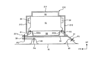
アッパーケース210は、フランジ部213を有しており、フランジ部213は、ロアーケース220に対して固定される。図3に示すように、電池スタック10の上面およびアッパーケース210の領域211の間には、スペースS1が形成されている。スペースS1は、電池モジュール11の温度調節に用いられる熱交換媒体が移動するスペースである。
The
図3に示すように、電池モジュール11の底面およびロアーケース220の間には、スペースS2が形成されている。スペースS2は、電池モジュール11の温度調節に用いられる熱交換媒体が移動するスペースである。熱交換媒体としては、例えば、空気や、空気とは異なる成分の気体を用いることができる。スペースS1,S2の一方は、電池モジュール11に熱交換媒体を供給する通路(供給通路)として用いることができ、他方は、電池モジュール11からの熱交換媒体を排出する通路(排出通路)として用いることができる。
As shown in FIG. 3, a space S <b> 2 is formed between the bottom surface of the
隣り合って配置される2つの電池モジュール11の間には、スペースが形成されており、このスペースには、供給通路(スペースS1又はS2)からの熱交換媒体が進入する。ここで、2つの電池モジュール11における互いに向かい合う側面に突起を形成しておけば、2つの電池モジュール11の間にスペースを形成することができる。2つの電池モジュール11の間に形成されたスペースに進入した熱交換媒体は、排出通路(スペースS2又はS1)に向かって移動する。このとき、熱交換媒体は、電池モジュール11との間で熱交換を行うことによって、電池モジュール11の温度を調節することができる。
A space is formed between the two
電池モジュール11が発熱しているときには、冷却用の熱交換媒体(冷やされた熱交換媒体)を用いることにより、電池モジュール11の温度上昇を抑制することができる。また、電池モジュール11が過度に冷えているときには、加温用の熱交換媒体(温められた熱交換媒体)を用いることにより、電池モジュール11の温度低下を抑制することができる。
When the
図2に示すように、ロアーケース220は、3つの平坦部(プレート本体に相当する)221a〜221cと、一対の支持部222a,222bとを有する。本実施例において、平坦部221a〜221cは、平坦な面で構成されているが、凹凸形状が含まれていてもよい。
As shown in FIG. 2, the
平坦部221a〜221cおよび支持部222a,222bは、一体的に形成されており、支持部222a,222bは、ロアーケース220の一部を曲げ加工することによって構成されている。支持部222a,222bは、車両100の左右方向(矢印LH又は矢印RHの方向)に延びている。また、支持部222a,222bは、平坦部221a〜221cから電池スタック10の側(すなわち、上方)に突出しており、電池スタック10を支持するために用いられる。
The
支持部222aは、支持部222bよりも車両100の前方に位置している。平坦部221aは、支持部222aよりも、車両100の前方に位置している。平坦部221bは、一対の支持部222a,222bの間に位置している。平坦部221cは、支持部222bよりも、車両100の後方側に位置している。
The
支持部222a,222bの上面は、電池モジュール11の底面と接触しており、支持部222a,222bおよび電池モジュール11は、図3に示す締結位置P1,P2において、締結部材によって互いに固定される。締結位置P1,P2は、複数設けられており、複数の締結位置P1,P2は、支持部222a,222bの長手方向に沿って配置されている。
The upper surfaces of the
支持部222a,222bおよび電池モジュール11の締結構造としては、例えば、電池モジュール11の底面にネジ溝が形成されているとともに、支持部222a,222bの上面に開口部が形成されている。ボルトは、支持部222a,222bの開口部を通過して、電池モジュール11のネジ溝と係合する。これにより、電池モジュール11がロアーケース220(支持部222a,222b)に固定される。
As the fastening structure of the
電池スタック10を構成する各電池モジュール11を支持部222a,222bに固定することができる。また、上述したように、電池スタック10に拘束力を与えた構造では、特定の電池モジュール11だけを支持部222a,222bに固定することもできる。
Each
ロアーケース220の底面には、一対のリインフォース40が固定されている。例えば、リインフォース40およびロアーケース220は、溶接によって固定することができる。リインフォース40は、車両100の前後方向に延びている。リインフォース40のうち、車両100の後方側に位置する端部は、傾斜面41を有している。
A pair of
ロアーケース220の平坦部221aおよびリインフォース40は、締結位置P3において、締結部材によってブラケット50に固定されている。また、ブラケット50は、締結位置P4において、締結部材によってクロスメンバ60に固定されている。クロスメンバ60は、車両100の横方向に延びており、フロアパネル70と接続されている。ブラケット50は、クロスメンバ60の上面と接触している。図3に示すように、電池スタック10の一部は、クロスメンバ60よりも車両100の前方に位置している。
The
リインフォース40の傾斜面41および台座80は、締結位置P5において、締結部材によって互いに固定されている。ここで、傾斜面41は、台座80の傾斜面に沿って配置されている。台座80は、フロアパネル70と接続されている。図3に示すように、電池スタック10は、台座80よりも車両100の前方に配置されている。
The
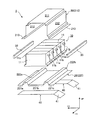
図4および図5は、ロアーケース220およびリインフォース40を互いに異なる方向から見たときの斜視図である。図6は、図4の矢印Aで示す方向から見たときの図である。
4 and 5 are perspective views when the
ロアーケース220には、複数の補強ビード(突起部に相当する)223が形成されている。具体的には、各補強ビード223は、ロアーケース220の上面、言い換えれば、電池スタック10と対向するロアーケース220の面に形成されている。また、補強ビード223は、各支持部222a,222bの側面と平坦部221bとに、またがって形成されており、支持部222a,222bおよび平坦部221bから突出している。
The
補強ビード223は、支持部222a,222bが延びる方向(矢印LH又はRHの方向)と直交する平面内に配置されている。具体的には、補強ビード223のうち、支持部222a,222bに形成された部分は、車両100の上下方向に延びており、補強ビード223のうち、平坦部221bに形成された部分は、車両100の前後方向に延びている。ここで、本実施例では、支持部222a,222bが延びる方向と直交する平面内に、補強ビード223を配置しているが、これに限るものではない。具体的には、補強ビード223は、支持部222a,222bが延びる方向と直交する平面に対して傾いていてもよい。
The reinforcing
複数の補強ビード223は、支持部222a,222bが延びる方向に並んでおり、一対の支持部222a,222bの間に位置している。図6に示すように、補強ビード223は、支持部222a,222bや平坦部221bから、電池スタック10の側に向かって突出している。
The plurality of reinforcing
ロアーケース220の支持部222a,222bは、電池スタック10の側に向かって凸となるように曲げ加工されているため、外力を受けたときに変形してしまうことがある。また、支持部222a,222bには電池スタック10が固定されているため、支持部222a,222bの変形によって、支持部222a,222bおよび電池スタック10の固定部分に過度の負荷がかかってしまうおそれがある。
Since the
本実施例では、電池パック1がラゲッジルームLRに配置されているため、車両100の後部が衝突したときに、電池パック1が外力を受けるおそれがある。このとき、電池パック1は、車両100の後方からの外力を受けて、車両100の前方に向かって変位することがある。
In the present embodiment, since the
電池パック1が車両100の前方に向かって変位すると、支持部222a,222bの変形によって、支持部222a,222bが倒れてしまうことがある。支持部222a,222bが倒れることによって、電池スタック10およびロアーケース220の間に形成されたスペースS2が減少することになる。このような支持部222a,222bの変形によって、支持部222a,222bおよび電池モジュール11の締結部分(締結位置P1,P2の部分)に、過度の負荷がかかってしまうことがある。
When the
そこで、本実施例では、ロアーケース220に補強ビード223を設けることにより、支持部222a,222bの強度を向上させ、外力を受けた支持部222a,222bを変形し難くしている。すなわち、支持部222a,222bが変形しやすい部分(平坦部221bとの接続部分)に関して、補強ビード223を用いてロアーケース220の厚さを確保しておくことにより、支持部222a,222bの変形を抑制することができる。
Therefore, in this embodiment, the
また、本実施例において、補強ビード223は、電池モジュール11および支持部222a,222bの締結部分(締結位置P1,P2の部分)に対応した位置に設けられている。具体的には、補強ビード223および締結部分は、支持部222a,222bが延びる方向と直交する面内において、並んで配置されている。このように補強ビード223を配置することにより、電池モジュール11および支持部222a,222bの締結部分における強度を確保することができる。
In the present embodiment, the reinforcing
本実施例では、ロアーケース220および電池スタック10の間にスペースS2を形成しているが、このスペースS2を利用して、補強ビード223を設けている。このため、補強ビード223を配置するためのスペースを確保しやすくなる。
In this embodiment, a space S2 is formed between the
本実施例では、補強ビード223を用いているが、これに限るものではなく、補強ビード223と同様の機能を発揮できるものを用いることができる。例えば、補強ビード223の代わりに、支持部222a,222bの側面および平坦部221bに沿って配置される補強板(突起部に相当する)を用いることもできる。補強板は、支持部222a,222bおよび平坦部221bに対して固定される。また、補強板は、支持部222a,222bが延びる方向と直交する平面に沿って配置することができる。
In this embodiment, the reinforcing
本実施例では、支持部222a,222bの一側面および平坦部221bに、補強ビード223を設けているが、これに限るものではない。すなわち、支持部222a,222bおよび平坦部221a〜221cをまたぐ位置に、補強ビード223が設けられていればよい。例えば、支持部222aの側面および平坦部221aにまたがる位置に補強ビード223を設けたり、支持部222bの側面および平坦部221cにまたがる位置に補強ビード223を設けたりすることができる。上述した点を考慮して、補強ビード223を設ける位置を適宜設定することができる。
In this embodiment, the reinforcing
1:電池パック 10:電池スタック(蓄電装置)
11:電池モジュール(蓄電素子) 20:パックケース
210:アッパーケース 220:ロアーケース(搭載プレート)
221a〜221c:平坦部(プレート本体) 222a,222b:支持部
223:補強ビード(突起部) 30:バスバーモジュール
40:リインフォース
1: Battery pack 10: Battery stack (power storage device)
11: Battery module (storage element) 20: Pack case 210: Upper case 220: Lower case (mounting plate)
221a-221c: Flat part (plate main body) 222a, 222b: Support part 223: Reinforcement bead (protrusion part) 30: Busbar module 40: Reinforce
Claims (8)
前記蓄電装置が搭載される搭載プレートと、を有しており、
前記搭載プレートは、
プレート本体と、
曲げ加工によって前記プレート本体から前記蓄電装置の側に突出しており、先端に前記蓄電装置が固定される支持部と、
前記蓄電装置が位置する側において、前記プレート本体および前記支持部にまたがって設けられ、前記プレート本体および前記支持部から突出する突起部と、
を有することを特徴とする蓄電装置の搭載構造。 A power storage device for charging and discharging; and
A mounting plate on which the power storage device is mounted;
The mounting plate is
The plate body,
Projecting from the plate body to the power storage device side by bending, and a support portion to which the power storage device is fixed at the tip;
On the side where the power storage device is located, a projection that is provided across the plate body and the support, and protrudes from the plate body and the support,
A structure for mounting a power storage device, comprising:
前記支持部は、前記所定方向に延びていることを特徴とする請求項1又は2に記載の蓄電装置の搭載構造。 The power storage device has a plurality of power storage elements arranged in a predetermined direction,
The power storage device mounting structure according to claim 1, wherein the support portion extends in the predetermined direction.
The power storage device mounting structure according to any one of claims 1 to 7, wherein a power generation element that performs charging and discharging and an electrolytic solution are accommodated inside the power storage device.
Priority Applications (1)
| Application Number | Priority Date | Filing Date | Title |
|---|---|---|---|
| JP2011168393A JP5772354B2 (en) | 2011-08-01 | 2011-08-01 | Power storage device mounting structure |
Applications Claiming Priority (1)
| Application Number | Priority Date | Filing Date | Title |
|---|---|---|---|
| JP2011168393A JP5772354B2 (en) | 2011-08-01 | 2011-08-01 | Power storage device mounting structure |
Publications (2)
| Publication Number | Publication Date |
|---|---|
| JP2013032065A true JP2013032065A (en) | 2013-02-14 |
| JP5772354B2 JP5772354B2 (en) | 2015-09-02 |
Family
ID=47788333
Family Applications (1)
| Application Number | Title | Priority Date | Filing Date |
|---|---|---|---|
| JP2011168393A Active JP5772354B2 (en) | 2011-08-01 | 2011-08-01 | Power storage device mounting structure |
Country Status (1)
| Country | Link |
|---|---|
| JP (1) | JP5772354B2 (en) |
Cited By (3)
| Publication number | Priority date | Publication date | Assignee | Title |
|---|---|---|---|---|
| JP2015123800A (en) * | 2013-12-25 | 2015-07-06 | トヨタ自動車株式会社 | Vehicle panel structure |
| CN106252544A (en) * | 2015-06-04 | 2016-12-21 | 本田技研工业株式会社 | Electrical storage device |
| JP2022156741A (en) * | 2021-03-31 | 2022-10-14 | トヨタ自動車株式会社 | battery module |
Citations (4)
| Publication number | Priority date | Publication date | Assignee | Title |
|---|---|---|---|---|
| JPH07323735A (en) * | 1994-05-31 | 1995-12-12 | Nissan Motor Co Ltd | Battery mounting structure of electric vehicle |
| JPH08188096A (en) * | 1994-08-25 | 1996-07-23 | Kankyocho Kokuritsu Kankyo Kenkyusho | Bumper fitting construction of automobile |
| JP2001229897A (en) * | 2000-02-15 | 2001-08-24 | Toyota Motor Corp | Assembled battery, method to fix battery and motor vehicle |
| JP2010000864A (en) * | 2008-06-19 | 2010-01-07 | Mazda Motor Corp | Front body structure of vehicle |
-
2011
- 2011-08-01 JP JP2011168393A patent/JP5772354B2/en active Active
Patent Citations (4)
| Publication number | Priority date | Publication date | Assignee | Title |
|---|---|---|---|---|
| JPH07323735A (en) * | 1994-05-31 | 1995-12-12 | Nissan Motor Co Ltd | Battery mounting structure of electric vehicle |
| JPH08188096A (en) * | 1994-08-25 | 1996-07-23 | Kankyocho Kokuritsu Kankyo Kenkyusho | Bumper fitting construction of automobile |
| JP2001229897A (en) * | 2000-02-15 | 2001-08-24 | Toyota Motor Corp | Assembled battery, method to fix battery and motor vehicle |
| JP2010000864A (en) * | 2008-06-19 | 2010-01-07 | Mazda Motor Corp | Front body structure of vehicle |
Cited By (7)
| Publication number | Priority date | Publication date | Assignee | Title |
|---|---|---|---|---|
| JP2015123800A (en) * | 2013-12-25 | 2015-07-06 | トヨタ自動車株式会社 | Vehicle panel structure |
| CN105829191A (en) * | 2013-12-25 | 2016-08-03 | 丰田自动车株式会社 | Vehicle panel structure |
| US9758028B2 (en) | 2013-12-25 | 2017-09-12 | Toyota Jidosha Kabushiki Kaisha | Vehicle panel structure |
| CN106252544A (en) * | 2015-06-04 | 2016-12-21 | 本田技研工业株式会社 | Electrical storage device |
| US10903462B2 (en) | 2015-06-04 | 2021-01-26 | Honda Motor Co., Ltd. | Electric storage device |
| JP2022156741A (en) * | 2021-03-31 | 2022-10-14 | トヨタ自動車株式会社 | battery module |
| JP7380628B2 (en) | 2021-03-31 | 2023-11-15 | トヨタ自動車株式会社 | battery module |
Also Published As
| Publication number | Publication date |
|---|---|
| JP5772354B2 (en) | 2015-09-02 |
Similar Documents
| Publication | Publication Date | Title |
|---|---|---|
| JP5733089B2 (en) | Power storage device mounting structure | |
| JP7037007B2 (en) | Battery pack with extended battery module structure | |
| JP5198522B2 (en) | Power storage device and vehicle | |
| JP6019125B2 (en) | Battery module assembly with improved reliability and medium-to-large battery pack including the same | |
| JP5847377B2 (en) | Power supply device and vehicle equipped with the same | |
| JP5843003B2 (en) | vehicle | |
| KR20170053429A (en) | Battery Module improved impact resistance | |
| WO2018235556A1 (en) | Power supply device, vehicle equipped with same, and electricity storage device | |
| JP5741406B2 (en) | In-vehicle structure of power storage device | |
| US9566853B2 (en) | Vehicle | |
| CN103890997A (en) | Middle and large-sized battery pack assembly | |
| JP5846045B2 (en) | vehicle | |
| US12036878B2 (en) | Power supply device, vehicle having power supply device, and power storage device | |
| US11990636B2 (en) | Power supply device, electric vehicle using same, and power storage device | |
| WO2021199493A1 (en) | Power supply device, vehicle provided with same, and power storage device | |
| WO2018235557A1 (en) | Power supply device, vehicle provided with same, and power storage device | |
| JP2021534550A (en) | Battery packs and electronic devices including cover structures and automobiles | |
| WO2020194937A1 (en) | Power supply device, and electric vehicle and electrical storage device each equipped with same | |
| JP5772354B2 (en) | Power storage device mounting structure | |
| JP2012003869A (en) | Power storage device | |
| KR102416817B1 (en) | Enclosure of battery pack, battery pack and automobileusing the same | |
| KR20130110951A (en) | Battery pack of compact structure | |
| JP2022508487A (en) | Battery packs and electronic devices with connection plates and automobiles | |
| WO2020194930A1 (en) | Power supply device, electric vehicle using same, and power storage device | |
| CN115764101A (en) | Automobile chassis and automobile |
Legal Events
| Date | Code | Title | Description |
|---|---|---|---|
| A621 | Written request for application examination |
Free format text: JAPANESE INTERMEDIATE CODE: A621 Effective date: 20140116 |
|
| A977 | Report on retrieval |
Free format text: JAPANESE INTERMEDIATE CODE: A971007 Effective date: 20141120 |
|
| A131 | Notification of reasons for refusal |
Free format text: JAPANESE INTERMEDIATE CODE: A131 Effective date: 20141202 |
|
| A521 | Written amendment |
Free format text: JAPANESE INTERMEDIATE CODE: A523 Effective date: 20150129 |
|
| TRDD | Decision of grant or rejection written | ||
| A01 | Written decision to grant a patent or to grant a registration (utility model) |
Free format text: JAPANESE INTERMEDIATE CODE: A01 Effective date: 20150602 |
|
| A61 | First payment of annual fees (during grant procedure) |
Free format text: JAPANESE INTERMEDIATE CODE: A61 Effective date: 20150615 |
|
| R151 | Written notification of patent or utility model registration |
Ref document number: 5772354 Country of ref document: JP Free format text: JAPANESE INTERMEDIATE CODE: R151 |