JP2013018381A - Electric power steering device - Google Patents
Electric power steering device Download PDFInfo
- Publication number
- JP2013018381A JP2013018381A JP2011153539A JP2011153539A JP2013018381A JP 2013018381 A JP2013018381 A JP 2013018381A JP 2011153539 A JP2011153539 A JP 2011153539A JP 2011153539 A JP2011153539 A JP 2011153539A JP 2013018381 A JP2013018381 A JP 2013018381A
- Authority
- JP
- Japan
- Prior art keywords
- steering
- value
- midpoint
- absolute value
- vehicle
- Prior art date
- Legal status (The legal status is an assumption and is not a legal conclusion. Google has not performed a legal analysis and makes no representation as to the accuracy of the status listed.)
- Withdrawn
Links
Images


Abstract
Description
本発明は、操舵補助トルク発生用アクチュエータをステアリングホイールの中点からの操舵量に応じて制御する電動パワーステアリング装置に関するものである。 The present invention relates to an electric power steering apparatus that controls a steering assist torque generating actuator according to a steering amount from a middle point of a steering wheel.
ステアリングホイールの中点からの操舵量に応じて操舵補助トルク発生用アクチュエータを制御する場合、その中点が不正確であると車両の進行方向が偏る虞がある。
そのため、トルクセンサによる検出操舵トルクが零である時点のステアリングホイールの相対的な検出操舵量を中点として設定することが行なわれている。
When the steering assist torque generating actuator is controlled according to the steering amount from the middle point of the steering wheel, if the middle point is inaccurate, the traveling direction of the vehicle may be biased.
Therefore, the relative detected steering amount of the steering wheel when the detected steering torque by the torque sensor is zero is set as the midpoint.
しかし、車両がバンク路を走行している際に、ドライバーがステアリングホイールから手を離したような場合、操舵トルクは零であるが、車両は直進できないため、そのような中点設定の仕方では中点を正確に求めることはできない。そこで、車両のヨーレートや横加速度の検出値に基づいて、それらが直進判定用範囲内である時に、車両が直進状態であると判定し、車両が直進状態である時の相対的な検出舵角位置を、中点として設定することが提案されている(特許文献1参照)。 However, when the vehicle is driving on a bank road, if the driver releases his hand from the steering wheel, the steering torque is zero, but the vehicle cannot go straight. The midpoint cannot be determined accurately. Therefore, based on the detected values of the yaw rate and lateral acceleration of the vehicle, when they are within the straight travel determination range, it is determined that the vehicle is in the straight travel state, and the relative detected steering angle when the vehicle is in the straight travel state It has been proposed to set the position as a midpoint (see Patent Document 1).
ところが、このような複数の車両直進状態検出値が、直進判定用範囲内である時に車両が直進状態であると判定すると、複数の車両直進状態検出値が零となった後でも、直進判定用範囲外となるまで検出舵角位置を中点として設定する。
その結果、ステアリングホイールの中点に誤差が生じ、その中点からの操舵量に応じた制御の適正化が低下する場合がある。この点において、なお改善の余地を残すものとなっていた。
However, if it is determined that the vehicle is in the straight traveling state when the plurality of vehicle straight traveling state detection values are within the straight traveling determination range, the straight traveling determination value is used even after the plurality of vehicle straight traveling state detection values become zero. The detected rudder angle position is set as the midpoint until it is out of range.
As a result, an error occurs at the midpoint of the steering wheel, and the optimization of the control according to the steering amount from the midpoint may be reduced. In this respect, there was still room for improvement.
本発明は、上記問題点を解決するためになされたものであって、その目的は、特に、ステアリングホイールの中点を正確に設定することで、その中点からの操舵量に応じた制御の適正化を図ることのできる電動パワーステアリング装置を提供することにある。 The present invention has been made in order to solve the above-mentioned problems, and the object of the present invention is to control the control according to the steering amount from the middle point, particularly by setting the middle point of the steering wheel accurately. An object is to provide an electric power steering device that can be optimized.
上記課題を解決するために、請求項1に記載の発明は、ステアリングホイール(1)の操舵トルクを検出するトルクセンサ(11)と、検出操舵トルクに応じた操舵補助トルクを発生するアクチュエータ(10)と、設定中点に対する前記ステアリングホイール(1)の相対的な操舵量を検出する操舵量センサ(12)と、前記操舵量の設定中点を記憶する中点記憶部(20)と、車両の進行方向に応じて変化する変量を所定の周期で検出するヨーレートセンサ(13)を含む複数の変量検出部(20)と、前記アクチュエータを制御する制御部(20)と、を備え、前記制御部(20)は、前記複数の変量検出部(20)の検出値の絶対値が所定の範囲内にあり、かつ、前記ヨーレートセンサ(13)の検出値の今回値の絶対値が前回値の絶対値より小さいという学習条件を満たすときに、その時点の前記検出操舵量を設定中点として前記中点記憶部(20)に記憶し、設定された設定中点からの検出操舵量に応じて、前記アクチュエータ(10)を制御すること、を要旨とする。
In order to solve the above-mentioned problem, the invention according to
本発明によれば、ヨーレートセンサを含む複数の変量検出部の検出値の絶対値が所定の範囲内にあり、かつ、ヨーレートセンサの検出値の今回値の絶対値が前回値の絶対値より小さいという学習条件を満たすときに、その時点の検出操舵量を設定中点として記憶される。即ち、ヨーレートセンサを含む複数の変量検出部の検出値の絶対値が所定の範囲内にあるので、車両はほぼ直進状態であると判定される。 According to the present invention, the absolute values of the detected values of the plurality of variable detectors including the yaw rate sensor are within a predetermined range, and the absolute value of the current value of the detected value of the yaw rate sensor is smaller than the absolute value of the previous value. When the learning condition is satisfied, the detected steering amount at that time is stored as a setting midpoint. That is, since the absolute values of the detection values of the plurality of variable detection units including the yaw rate sensor are within a predetermined range, it is determined that the vehicle is in a substantially straight traveling state.
更に、複数の変量検出部の中でも特に、ヨーレートセンサは車両が停止するたびに零点補正を行なうので、変量の検出精度が特に高い。変量の検出精度が高いヨーレートセンサに着目して、更に、ヨーレートセンサの検出値の今回値の絶対値が前回値の絶対値より小さいという学習条件を満たすときに、その時点の前記検出操舵量を設定中点として前記中点記憶部に記憶するようにしている。よって、ステアリングホイールの中点が不正確に特定させるのを防止できる。
その結果、中点からの操舵量に応じた制御の適正化を図ることができる。
Furthermore, among the plurality of variable quantity detection units, the yaw rate sensor performs zero point correction each time the vehicle stops, so that the variable detection accuracy is particularly high. Focusing on the yaw rate sensor with high variable detection accuracy, and further when the learning condition that the absolute value of the current value of the detected value of the yaw rate sensor is smaller than the absolute value of the previous value is satisfied, the detected steering amount at that time is The set midpoint is stored in the midpoint storage unit. Therefore, it is possible to prevent the midpoint of the steering wheel from being specified incorrectly.
As a result, it is possible to optimize the control according to the steering amount from the midpoint.
請求項2に記載の発明は、前記制御部は、前記操舵量センサの今回値の絶対値が前回値の絶対値より小さいことを更なる学習条件とすること、を要旨とする。
The gist of the invention described in
上記構成によれば、制御部は、操舵量センサの今回値の絶対値が前回値の絶対値より小さいことを更なる学習条件とする。よって、変量検出部と操舵量センサが複数条件を満たすときにのみ中点学習するので、より確実で精度の高い中点学習が可能となる。
その結果、中点からの操舵量に応じた制御の適正化をより厳格に図ることができる。
According to the above configuration, the control unit sets the further learning condition that the absolute value of the current value of the steering amount sensor is smaller than the absolute value of the previous value. Therefore, since the midpoint learning is performed only when the variable amount detection unit and the steering amount sensor satisfy a plurality of conditions, midpoint learning with higher accuracy and higher accuracy is possible.
As a result, it is possible to more strictly optimize the control according to the steering amount from the midpoint.
本発明の電動パワーステアリング装置によれば、ステアリングホイールの中点を正確に設定することで、その中点からの操舵量に応じた制御の適正化を図ることができる。 According to the electric power steering apparatus of the present invention, by appropriately setting the middle point of the steering wheel, it is possible to optimize the control according to the steering amount from the middle point.
図1に示す車両100の電動パワーステアリング装置Aにおいては、ステアリングホイール1に連結されるステアリングシャフト2にユニバーサルジョイント3を介してピニオン4が接続され、ピニオン4に噛合うラック5の各端に左右前車輪6fがタイロッド7、ナックルアーム8等を介して接続される。これにより、操舵によるステアリングホイール1の回転がピニオン4に伝達されることで、ラック5が車両幅方向に移動し、このラック5の動きが車輪6fに伝達されることで、舵角が変化する。
また、ステアリングシャフト2に減速ギヤ機構9を介して、電動モータにより構成される操舵補助トルク発生用アクチュエータ10が接続される。アクチュエータ10の出力が、減速ギヤ機構9を介してステアリングシャフト2に伝達されることで操舵補助トルクが付与される。
In the electric power steering apparatus A of the
Further, a steering assist
左右前車輪6fとエンジン40により変速ギヤ機構、差動ギヤ機構等を介して駆動される左右後車輪6rの制動機構が設けられている。即ち、制動機構は、ブレーキペダル51の踏力に応じた各車輪6f、6rの制動圧を発生するマスターシリンダ52と、その制動圧を増幅する制動圧制御ユニット50と、各車輪6f、6rのブレーキ装置54におけるブレーキシューをブレーキドラムに押し付けるホイルシリンダ圧として分配されることで各車輪6f、6rに制動力が作用する。
A braking mechanism is provided for the left and right
操舵補助トルク発生用アクチュエータ10、エンジン40を制御するための電動バルブ等のエンジン制御機器、制動圧制御ユニット50はコンピュータにより構成される制御装置20に接続される。制御装置20に、ステアリングシャフト2の操舵トルクτを検出するトルクセンサ11、ステアリングホイール1の相対的な操舵量としてステアリングシャフト2の回転角に対応する操舵角θを検出する操舵量センサ12、ヨーレートγを検出するヨーレートセンサ13、横加速度Gyを検出する横加速度センサ14、各車輪6f、6rそれぞれの車輪速を検出する車輪速センサ15、車速Vを検出する車速センサ16が接続される。
ヨーレートγ、横加速度Gy、左右車輪速差は車両100の進行方向変化時に変化する変量であることから、ヨーレートセンサ13、横加速度センサ14、各車輪速センサ15及び車輪速センサ15により検出される、各車輪6fの車輪速から左右車輪速差を演算する制御装置20は、本発明の変量検出部を構成する。
The steering assist
Since the yaw rate γ, the lateral acceleration Gy, and the left and right wheel speed difference are variables that change when the traveling direction of the
制御装置20は、アクチュエータ10を制御する制御部として機能し、検出操舵トルクτに応じた操舵補助トルクを発生するようにアクチュエータ10を制御し、さらに本実施形態では、検出車速Vに応じても操舵補助トルクを変化させ、操舵トルクτの大きさが大きく、車速Vが小さい程に操舵補助トルクを増加させる。
The
また、アクチュエータ10の制御部として機能する制御装置20は、ステアリングホイール1の設定された中点からの検出操舵角θhに応じてアクチュエータ10を制御する。例えば、中点からの検出操舵角θhの大きさが設定値以下の場合は、操舵トルクτが増加しても操舵補助トルクを発生させないように、アクチュエータ10を制御することで、直進走行の安定性を増加させる制御や、中点からの操舵角θhの大きさが減少する時に、中点からの操舵角θhに応じて操舵補助トルクを変化させることでステアリングホイール1の中点位置への収斂性を向上する制御等を行う。
In addition, the
尚、このような制御は中点が設定されるまでは、行わないようにしてもよいし、中点が設定されるまでは、例えば、最初の検出操舵角θhを仮中点として制御を行ってもよい。そして、制御装置20は、ステアリングホイール1の中点を設定するための中点記憶部として機能する。
Such control may not be performed until the midpoint is set. Until the midpoint is set, for example, the control is performed with the first detected steering angle θh as the temporary midpoint. May be. The
本実施形態においては、検出ヨーレートγの大きさが設定値以上である時、横加速度Gyの大きさが設定値以上である時、あるいは、左右車輪速差の大きさが設定値以上である時、車両100は直進状態ではないと判定される。また、車両100の安定化制御を行っていないか否かに応じて、車両100が直進状態か否かの判定を補助してもよい。
In the present embodiment, when the detected yaw rate γ is greater than or equal to the set value, when the lateral acceleration Gy is greater than or equal to the set value, or when the difference between the left and right wheel speeds is greater than or equal to the set value. It is determined that
その安定化制御として、例えば、車輪速に基づき車輪6f、6rのロックを防止するよう制動圧制御ユニット50を制御するABS制御、車輪6f、6rの空転を防止するよう制動圧制御ユニット50やエンジン40を制御するトラクション制御、アンダーステア状態やオーバーステア状態を防止するように制動圧制御ユニット50やエンジン40を制御する姿勢安定化制御等を行っている時、車両100は直進状態ではないと判定される。
As the stabilization control, for example, ABS control for controlling the braking
さらに、車両100の車速、加速度、前後車輪速差の大きさに応じて車両100が直進状態か否かの判定を補助してもよい。例えば、車両100の加速度の大きさが設定値以上である時、前後車輪速差の大きさが設定値以上である時、あるいは、車速Vの大きさが設定値以下である時、車両100は安定して直進していないので、直進状態ではないと判定される。中点記憶部は、車両100が直進状態であると判定される時点の検出操舵量を、設定中点として記憶する。
Further, it may be possible to assist in determining whether the
図2のフローチャートは、制御装置20によるアクチュエータ10の制御手順を示す。まず、各センサの検出値を読み込み(ステップS1)、ステアリングホイール1の中点
の設定を行なう(ステップS2)。尚、制御開始当初においては、当初の相対的な検出操舵角θhを中点が設定されるまでの仮中点として記憶する。
The flowchart of FIG. 2 shows a control procedure of the
次に、操舵補助力トルクτaを演算する(ステップS3)。この演算は、操舵トルクτと、車速Vと、操舵補助力トルクτaとの関係を予め定めて記憶し、その関係と検出した操舵トルクτと、車速Vとから、操舵補助力トルクτaを求めることで行なうことができる。 Next, the steering assist force torque τa is calculated (step S3). In this calculation, the relationship between the steering torque τ, the vehicle speed V, and the steering assist force torque τa is determined and stored in advance, and the steering assist force torque τa is obtained from the relationship and the detected steering torque τ and the vehicle speed V. Can be done.
次に、ステアリングホイール1の中点からの検出操舵角θhに応じて、操舵補助力トルクτaを補正する(ステップS4)。例えば、中点からの検出操舵角θhの大きさが、設定値以下の場合は、操舵補助力トルクτaを零としたり、中点からの操舵角θhの大きさが減少する場合は、増加する場合よりも中点からの操舵角θhに応じて、操舵補助トルクを予め設定した値だけ変化させる。次に、求めた、操舵補助力トルクτaを発生するようにアクチュエータ10を駆動する(ステップS5)。しかる後に、制御を終了するか否か、例えば、イグニッションスイッチがオフか否かに応じて判断し(ステップS6)、終了しない場合は(ステップS1)に戻る。
Next, the steering assist torque τa is corrected according to the detected steering angle θh from the middle point of the steering wheel 1 (step S4). For example, when the magnitude of the detected steering angle θh from the middle point is equal to or smaller than the set value, the steering assist force torque τa is set to zero, or increases when the magnitude of the steering angle θh from the middle point decreases. The steering assist torque is changed by a preset value in accordance with the steering angle θh from the middle point. Next, the
次に、変量検出部が満たす学習条件を図3〜図6に基づいて、また、操舵量センサが満たす学習条件を図7に基づいて説明する。
図3は、変量検出部としてのヨーレートセンサ13が検出するヨーレートγの挙動を示している(L1)。車両がほぼ直進状態になると、ヨーレートγは零点に近づく。ヨーレートγの零点から少し大きな値を所定の範囲γ0とする。所定の範囲γ0は実験値から決定する。そして、ヨーレートγの絶対値が所定の範囲γ0以下になったら車両がほぼ直進状態になったと判断する。更に、ヨーレートγの今回値(γ(n))P1の絶対値が、ヨーレートγの前回値(γ(n-1))Q1の絶対値より小さい場合には、車両が更に直進状態になったと判断できる。この条件をヨーレートセンサ13における、操舵量の中点を設定する学習条件としている。また、ヨーレートセンサは車両が停止するたびに零点補正を行なうので、複数の変量検出部の中でも、検出精度が特に高い。
Next, learning conditions satisfied by the variable amount detection unit will be described with reference to FIGS. 3 to 6, and learning conditions satisfied by the steering amount sensor will be described with reference to FIG. 7.
FIG. 3 shows the behavior of the yaw rate γ detected by the
図4は、変量検出部としての横加速度センサ14が検出する横加速度Gyの挙動を示している(L2)。車両がほぼ直進状態になると、横加速度Gyは零点に近づく。横加速度Gyの零点から少し大きな値を所定の範囲Gy0とする。所定の範囲Gy0は実験値から決定する。そして、横加速度Gyの絶対値が所定の範囲Gy0以下になったら車両がほぼ直進状態になったと判断する。具体的には、横加速度Gyの今回値(Gy(n))P2の絶対値が、所定の範囲Gy0以下になったら、車両が直進状態になったと判断する。この条件を横加速度センサ14における、操舵量の中点を設定する学習条件としている。
FIG. 4 shows the behavior of the lateral acceleration Gy detected by the
図5は、変量検出部としての前輪駆動時の左右車輪速センサ15が検出する、前輪駆動時の左右車輪速差の絶対値|W1-W2|の挙動を示している(L3)。車両がほぼ直進状態になると、左右車輪速差の絶対値|W1-W2|は零点に近づく。左右車輪速差の絶対値|W1-W2|の零点から少し大きな値を所定の範囲W01とする。所定の範囲W01は実験値から決定する。そして、左右車輪速差の絶対値|W1-W2|が所定の範囲W01以下になったら、車両がほぼ直進状態になったと判断する。具体的には、左右車輪速差の絶対値|W1-W2|の今回値の絶対値|W1(n)-W2(n)|P3が、所定の範囲W01以下になったら、車両が直進状態になったと判断する。この条件を前輪駆動時の左右車輪速センサ15における、操舵量の中点を設定する学習条件としている。
FIG. 5 shows the behavior of the absolute value | W1−W2 | of the left and right wheel speed difference when driving the front wheels, which is detected by the left and right
図6は、変量検出部としての後輪駆動時の左右車輪速センサ15が検出する、後輪駆動時の左右車輪速差の絶対値|W3-W4|の挙動を示している(L4)。車両がほぼ直進状態になると、左右車輪速差の絶対値|W3-W4|は零点に近づく。左右車輪速差の絶対値|W3-W4|の零点から少し大きな値を所定の範囲W02とする。所定の範囲W02は実験値から決定する。そして、左右車輪速差の絶対値|W3-W4|が所定の範囲W02以下になったら、車両がほぼ直進状態になったと判断する。具体的には、左右車輪速差の絶対値|W3-W4|の今回値の絶対値|W3(n)-W4(n)|P4が、所定の範囲W02以下になったら、車両が直進状態になったと判断する。この条件を後輪駆動時の左右車輪速センサ15における、操舵量の中点を設定する学習条件としている。
FIG. 6 shows the behavior of the absolute value | W3−W4 | of the difference between the left and right wheel speeds when driving the rear wheels, which is detected by the left and right
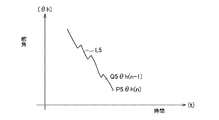
図7は、操舵量センサ12が検出する舵角θhの挙動を示している(L5)。ヨーレートγ、横加速度Gy、前輪駆動時の左右車輪速差の絶対値|W1-W2|または、後輪駆動時の左右車輪速差の絶対値|W3-W4|によって、車両がほぼ直進状態になったと学習され、舵角の今回値P5(θh(n))が舵角の前回値Q5(θh(n-1))より小さい場合には、車両がより直進状態になったと判断できる。この条件を操舵量センサ12における、操舵量の中点を設定する学習条件としている。
FIG. 7 shows the behavior of the steering angle θh detected by the steering amount sensor 12 (L5). The vehicle is almost linearly driven by the yaw rate γ, the lateral acceleration Gy, and the absolute value of the left and right wheel speed difference when driving the front wheels | W1-W2 | If the current value P5 (θh (n)) of the steering angle is smaller than the previous value Q5 (θh (n-1)) of the steering angle, it can be determined that the vehicle has gone straight ahead. This condition is used as a learning condition for setting the midpoint of the steering amount in the
図8のフローチャートは、制御装置20による中点設定手順を示す。
まず、ヨーレートγの前回値(γ(n-1))の絶対値が、所定の範囲γ0より小さく、かつ、ヨーレートγの今回値(γ(n))の絶対値が、所定の範囲γ0より小さいか否かを判定する(ステップS101)。ヨーレートγの今回値(γ(n))の絶対値が、所定の範囲γ0より小さく、かつ、ヨーレートγの今回値(γ(n))の絶対値が、所定の範囲γ0より小さいと判定された場合(ステップS101:YES)、ヨーレートγの今回値(γ(n))の絶対値が、ヨーレートγの前回値(γ(n-1))の絶対値より小さいか否かを判定する(ステップS102)。その設定値γ0は、車両100が実質的に直進している場合の最大値に設定すればよく、具体的な値は、実験的に求めればよい。
The flowchart of FIG. 8 shows the midpoint setting procedure by the
First, the absolute value of the previous value (γ (n−1)) of the yaw rate γ is smaller than the predetermined range γ0, and the current value (γ (n)) of the yaw rate γ is smaller than the predetermined range γ0. It is determined whether it is small (step S101). It is determined that the absolute value of the current value (γ (n)) of the yaw rate γ is smaller than the predetermined range γ0 and the absolute value of the current value (γ (n)) of the yaw rate γ is smaller than the predetermined range γ0. If this is the case (step S101: YES), it is determined whether the absolute value of the current value (γ (n)) of the yaw rate γ is smaller than the absolute value of the previous value of the yaw rate γ (γ (n-1)) ( Step S102). The set value γ0 may be set to a maximum value when the
次に、ヨーレートγの今回値(γ(n))の絶対値が、ヨーレートγの前回値(γ(n-1))の絶対値より小さいと判定された場合(ステップS102:YES)、横加速度Gyの今回値(Gy(n))の絶対値が、所定の範囲Gy0より小さいか否かを判定する(ステップS103)。その設定値Gy0は、車両100が実質的に直進している場合の最大値に設定すればよく、具体的な値は、実験的に求めればよい。
Next, when it is determined that the absolute value of the current value (γ (n)) of the yaw rate γ is smaller than the absolute value of the previous value (γ (n−1)) of the yaw rate γ (step S102: YES), It is determined whether or not the absolute value of the current value (Gy (n)) of the acceleration Gy is smaller than a predetermined range Gy0 (step S103). The set value Gy0 may be set to a maximum value when the
次に、横加速度Gyの今回値(Gy(n))の絶対値が、所定の範囲Gy0より小さいと判定された場合(ステップS103:YES)、前輪駆動時の左右車輪速差(W1-W2)の今回値|W1(n)-W2(n)|の絶対値が、所定の範囲W01より小さいか否かを判定する(ステップS104)。左右車輪速差(W1-W2)の今回値|W1(n)-W2(n)|の絶対値が、所定の範囲W01より小さいと判定された場合(ステップS104:YES)、舵角の今回値θh(n)の絶対値が、舵角の前回値θh(n-1)の絶対値より小さいか否かを判定する(ステップS105)。舵角の今回値θh(n)の絶対値が、舵角の前回値θh(n-1)の絶対値より小さいと判定された場合(ステップS105:YES)、その時点で検出されている相対的な舵角の今回値θh(n)を設定中点として記憶し(ステップS106)、アクチュエータ10の制御ルーチンにリターンする。
Next, when it is determined that the absolute value of the current value (Gy (n)) of the lateral acceleration Gy is smaller than the predetermined range Gy0 (step S103: YES), the difference between the left and right wheel speeds when driving the front wheels (W1-W2). ) Current value | W1 (n) −W2 (n) | is determined whether or not the absolute value is smaller than a predetermined range W01 (step S104). If it is determined that the absolute value of the current value | W1 (n) −W2 (n) | of the left and right wheel speed difference (W1−W2) is smaller than the predetermined range W01 (step S104: YES), the current steering angle It is determined whether or not the absolute value of the value θh (n) is smaller than the absolute value of the previous value θh (n−1) of the steering angle (step S105). When it is determined that the absolute value of the current value θh (n) of the steering angle is smaller than the absolute value of the previous value θh (n-1) of the steering angle (step S105: YES), the relative value detected at that time The current steering angle current value θh (n) is stored as a set midpoint (step S106), and the process returns to the control routine of the
また、ステップS104がNOの場合には、ステップS107に進む。
ステップS107では、後輪駆動時の左右車輪速差(W3-W4)の今回値|W3(n)-W4(n)|の絶対値が、所定の範囲W02より小さいか否かを判定する。左右車輪速差(W3-W4)の今回値|W3(n)-W4(n)|の絶対値が、所定の範囲W02より小さいと判定された場合(ステップS107:YES)には、ステップS105に進む。
尚、ステップS101〜ステップS104、ステップS105、およびステップS107における判定がNOである場合は、アクチュエータ10の制御ルーチンにリターンする。
If step S104 is NO, the process proceeds to step S107.
In step S107, it is determined whether or not the absolute value of the current value | W3 (n) −W4 (n) | of the left and right wheel speed difference (W3−W4) during rear wheel drive is smaller than a predetermined range W02. If it is determined that the absolute value of the current value | W3 (n) −W4 (n) | of the left and right wheel speed difference (W3−W4) is smaller than the predetermined range W02 (step S107: YES), step S105 is performed. Proceed to
If the determinations in steps S101 to S104, step S105, and step S107 are NO, the process returns to the control routine for the
以上、本実施形態によれば、以下のような作用・効果を得ることができる。
上述のように、単に複数の車両直進状態変量検出部の検出値が、直進判定用範囲内である時に車両が直進状態であると判定すると、複数の車両直進状態変量検出部の検出値が零となった後でも、直進判定用範囲外となるまで検出舵角位置を中点として設定する。
As described above, according to the present embodiment, the following operations and effects can be obtained.
As described above, when the detection values of the plurality of vehicle straight-ahead state variable detection units are within the straight-ahead determination range and it is determined that the vehicle is in a straight-ahead state, the detection values of the plurality of vehicle straight-ahead state variable detection units are zero. Even after becoming, the detected rudder angle position is set as a midpoint until it is out of the straight traveling determination range.
この点、本実施形態では、複数の車両直進状態変量検出部の検出値の絶対値が所定の範囲内にあり、かつ、車両が停止するたびに零点補正を行なう、変量の検出精度が高いヨーレートセンサに着目して、更に、ヨーレートセンサの検出値の今回値の絶対値が前回値の絶対値より小さいという学習条件を満たすときに、その時点の前記検出操舵量を設定中点として記憶することとした。 In this respect, in the present embodiment, the absolute value of the detection values of the plurality of vehicle straight-ahead state variable detection units is within a predetermined range, and zero correction is performed every time the vehicle stops, and the yaw rate with high variable detection accuracy Focusing on the sensor, when the learning condition that the current value of the detected value of the yaw rate sensor is smaller than the absolute value of the previous value is satisfied, the detected steering amount at that time is stored as a setting midpoint. It was.
更に、上記条件に、操舵量センサの今回値の絶対値が前回値の絶対値より小さいことを更なる学習条件とすることを加味した。このような構成にすれば、変量検出部と操舵量センサが複数条件を満たすときにのみ中点学習するので、ステアリングホイールの中点に誤差が生じることもなく、より確実で精度の高い中点学習が可能となる。
その結果、中点からの操舵量に応じた制御の適正化を図ることができる。
Furthermore, in addition to the above conditions, the fact that the absolute value of the current value of the steering amount sensor is smaller than the absolute value of the previous value is considered as a further learning condition. With this configuration, since the midpoint learning is performed only when the variable amount detection unit and the steering amount sensor satisfy a plurality of conditions, there is no error in the midpoint of the steering wheel, and a more reliable and accurate midpoint. Learning is possible.
As a result, it is possible to optimize the control according to the steering amount from the midpoint.
なお、本実施形態は以下のように変更してもよい。
・上記実施形態では、本発明を、所謂コラム型のEPSAに具体化したが、本発明は、所謂ピニオン型やラックアシスト型のEPSに適用してもよい。
In addition, you may change this embodiment as follows.
In the above embodiment, the present invention is embodied in a so-called column type EPSA, but the present invention may be applied to a so-called pinion type or rack assist type EPS.
・上記実施形態では、変量検出部として、前輪駆動時の左右車輪速差、または、後輪駆動時の左右車輪速差が所定の範囲に入った場合に、中点学習条件とした。しかし、これに限らず、前後輪左車輪速の平均と、前後輪右車輪速の平均との差が所定の範囲に入った場合に、中点学習条件としてもよい。 In the above embodiment, the variable point detection unit is set to the midpoint learning condition when the difference between the left and right wheel speeds when driving the front wheels or the difference between the left and right wheel speeds when driving the rear wheels falls within a predetermined range. However, the present invention is not limited to this, and the midpoint learning condition may be used when the difference between the average of the front and rear wheel left wheel speeds and the average of the front and rear wheel right wheel speeds falls within a predetermined range.
・上記実施形態では、操舵トルク値を変量検出手段として使用しなかったが、操舵トルク値を変量検出手段として使用し、操舵トルク値が所定の範囲に入った場合に、中点学習条件としてもよい。 In the above embodiment, the steering torque value is not used as the variable detection means. However, when the steering torque value is used as the variable detection means and the steering torque value falls within a predetermined range, the midpoint learning condition is also used. Good.
・上記実施形態では、変量検出部のサンプルリング毎に学習条件を満たす場合には、中点を設定したが、所定の時間を設定し、学習条件が所定の時間を経過したら中点を設定してもよい。 In the above embodiment, when the learning condition is satisfied for each sampling of the variable detection unit, the midpoint is set, but a predetermined time is set, and when the learning condition has passed the predetermined time, the midpoint is set. May be.
1:ステアリングホイール、2:ステアリングシャフト、
3:ユニバーサルジョイント、4:ピニオン、5:ラック、
7:タイロッド、8:ナックルアーム、9:減速ギヤ機構、
10:アクチュエータ、11:トルクセンサ、12:操舵量センサ、
13:ヨーレートセンサ(変量検出部)、14:横加速度センサ(変量検出部)、
15:車輪速センサ(変量検出部)、16:車速センサ、
20:制御装置(中点記憶部、制御部、変量検出部)、
40:エンジン、50:制動圧制御ユニット、51:ブレーキペダル、
52:マスターシリンダ、54:ブレーキ装置、100:車両、
6f:左右前車輪、6r:左右後車輪、
θh:操舵角、γ:ヨーレート、Gy:横加速度、V:車速、
τ:操舵トルク、τa:操舵補助力トルク、
γ0:ヨーレートγの所定の範囲、Gy0:横加速度Gyの所定の範囲、
W01:前輪駆動時の左右車輪速差の絶対値|W1-W2|の所定の範囲、
W02:後輪駆動時の左右車輪速差の絶対値|W3-W4|の所定の範囲
1: Steering wheel, 2: Steering shaft,
3: Universal joint, 4: Pinion, 5: Rack,
7: Tie rod, 8: Knuckle arm, 9: Reduction gear mechanism,
10: Actuator, 11: Torque sensor, 12: Steering amount sensor,
13: Yaw rate sensor (variable detector), 14: Lateral acceleration sensor (variable detector),
15: Wheel speed sensor (variable detector), 16: Vehicle speed sensor,
20: Control device (midpoint storage unit, control unit, variable amount detection unit),
40: engine, 50: braking pressure control unit, 51: brake pedal,
52: Master cylinder, 54: Brake device, 100: Vehicle,
6f: left and right front wheels, 6r: left and right rear wheels,
θh: steering angle, γ: yaw rate, Gy: lateral acceleration, V: vehicle speed,
τ: steering torque, τa: steering assist torque,
γ0: predetermined range of yaw rate γ, Gy0: predetermined range of lateral acceleration Gy,
W01: a predetermined range of the absolute value | W1-W2 | of the left and right wheel speed difference when driving the front wheels,
W02: A predetermined range of the absolute value | W3−W4 |
Claims (2)
検出操舵トルクに応じた操舵補助トルクを発生するアクチュエータと、
設定中点に対する前記ステアリングホイールの相対的な操舵量を検出する操舵量センサと、
前記操舵量の設定中点を記憶する中点記憶部と、
車両の進行方向に応じて変化する変量を所定の周期で検出するヨーレートセンサを含む複数の変量検出部と、
前記アクチュエータを制御する制御部と、を備え、
前記制御部は、
前記複数の変量検出部の検出値の絶対値が所定の範囲内にあり、かつ、前記ヨーレートセンサの検出値の今回値の絶対値が前回値の絶対値より小さいという学習条件を満たすときに、その時点の前記検出操舵量を設定中点として前記中点記憶部に記憶し、設定された設定中点からの検出操舵量に応じて、前記アクチュエータを制御することを特徴とする電動パワーステアリング装置。 A torque sensor for detecting the steering torque of the steering wheel;
An actuator that generates a steering assist torque according to the detected steering torque;
A steering amount sensor that detects a relative steering amount of the steering wheel with respect to a setting midpoint;
A midpoint storage unit for storing a set midpoint of the steering amount;
A plurality of variable detectors including a yaw rate sensor that detects a variable that changes according to the traveling direction of the vehicle at a predetermined period;
A control unit for controlling the actuator,
The controller is
When the absolute value of the detection values of the plurality of variable detection units is within a predetermined range, and the learning condition that the absolute value of the current value of the detection value of the yaw rate sensor is smaller than the absolute value of the previous value, The electric power steering apparatus characterized in that the detected steering amount at that time is stored as a setting midpoint in the midpoint storage unit, and the actuator is controlled in accordance with the detected steering amount from the set midpoint. .
前記操舵量センサの今回値の絶対値が前回値の絶対値より小さいことを更なる学習条件とする請求項1に記載の電動パワーステアリング装置。 The controller is
The electric power steering apparatus according to claim 1, wherein a further learning condition is that the absolute value of the current value of the steering amount sensor is smaller than the absolute value of the previous value.
Priority Applications (1)
| Application Number | Priority Date | Filing Date | Title |
|---|---|---|---|
| JP2011153539A JP2013018381A (en) | 2011-07-12 | 2011-07-12 | Electric power steering device |
Applications Claiming Priority (1)
| Application Number | Priority Date | Filing Date | Title |
|---|---|---|---|
| JP2011153539A JP2013018381A (en) | 2011-07-12 | 2011-07-12 | Electric power steering device |
Publications (1)
| Publication Number | Publication Date |
|---|---|
| JP2013018381A true JP2013018381A (en) | 2013-01-31 |
Family
ID=47690265
Family Applications (1)
| Application Number | Title | Priority Date | Filing Date |
|---|---|---|---|
| JP2011153539A Withdrawn JP2013018381A (en) | 2011-07-12 | 2011-07-12 | Electric power steering device |
Country Status (1)
| Country | Link |
|---|---|
| JP (1) | JP2013018381A (en) |
Cited By (2)
| Publication number | Priority date | Publication date | Assignee | Title |
|---|---|---|---|---|
| JP2014151897A (en) * | 2013-02-14 | 2014-08-25 | Honda Motor Co Ltd | Direct advance/turn determination device |
| WO2023171255A1 (en) * | 2022-03-11 | 2023-09-14 | 日野自動車株式会社 | Yaw rate calibration device |
-
2011
- 2011-07-12 JP JP2011153539A patent/JP2013018381A/en not_active Withdrawn
Cited By (2)
| Publication number | Priority date | Publication date | Assignee | Title |
|---|---|---|---|---|
| JP2014151897A (en) * | 2013-02-14 | 2014-08-25 | Honda Motor Co Ltd | Direct advance/turn determination device |
| WO2023171255A1 (en) * | 2022-03-11 | 2023-09-14 | 日野自動車株式会社 | Yaw rate calibration device |
Similar Documents
| Publication | Publication Date | Title |
|---|---|---|
| EP1577194B1 (en) | Steering apparatus for vehicle and method for controlling the same | |
| EP1731408B1 (en) | Vehicle steering apparatus | |
| US7740102B2 (en) | Steering control device for vehicle | |
| EP2492168A1 (en) | Electric power steering device for vehicle | |
| US20080142293A1 (en) | Steering Apparatus for Vehicle | |
| JP2014159269A (en) | Control method of four wheel steering vehicle | |
| JP2005343315A (en) | Vehicular steering device | |
| JP2018047827A (en) | Steering control apparatus | |
| JP4807162B2 (en) | Vehicle steering device | |
| JP2011110952A (en) | Device for controlling vehicle motion | |
| JP6048253B2 (en) | Steering control device | |
| JP5018166B2 (en) | Steering device | |
| JP2008037132A (en) | Electric power steering device | |
| JP2010234841A (en) | Rear wheel toe angle control system of vehicle | |
| JP2013018381A (en) | Electric power steering device | |
| JP2006213085A (en) | Electric power steering device | |
| JP5262871B2 (en) | Steering angle control device for vehicle and steering angle control method for vehicle | |
| JP2010215191A (en) | Vehicular steering device and vehicular steering method | |
| JP4556643B2 (en) | Vehicle braking / driving force control device | |
| JP4492289B2 (en) | Power steering device | |
| JP2008174168A (en) | Rear wheel steering control device for vehicle | |
| JP2013014226A (en) | Electric power steering device | |
| JP5303333B2 (en) | Vehicle rear wheel steering control device | |
| JP2005193779A (en) | Vehicle steering device | |
| JP2010155473A (en) | Turning behavior detection device, turning behavior detecting method, and yaw rate estimating method |
Legal Events
| Date | Code | Title | Description |
|---|---|---|---|
| A300 | Withdrawal of application because of no request for examination |
Free format text: JAPANESE INTERMEDIATE CODE: A300 Effective date: 20141007 |