JP2013011602A - Method and apparatus for measuring space with limited access - Google Patents
Method and apparatus for measuring space with limited access Download PDFInfo
- Publication number
- JP2013011602A JP2013011602A JP2012136830A JP2012136830A JP2013011602A JP 2013011602 A JP2013011602 A JP 2013011602A JP 2012136830 A JP2012136830 A JP 2012136830A JP 2012136830 A JP2012136830 A JP 2012136830A JP 2013011602 A JP2013011602 A JP 2013011602A
- Authority
- JP
- Japan
- Prior art keywords
- tube
- flange
- measurement
- space
- measuring
- Prior art date
- Legal status (The legal status is an assumption and is not a legal conclusion. Google has not performed a legal analysis and makes no representation as to the accuracy of the status listed.)
- Granted
Links
Images


Classifications
-
- G—PHYSICS
- G01—MEASURING; TESTING
- G01B—MEASURING LENGTH, THICKNESS OR SIMILAR LINEAR DIMENSIONS; MEASURING ANGLES; MEASURING AREAS; MEASURING IRREGULARITIES OF SURFACES OR CONTOURS
- G01B3/00—Measuring instruments characterised by the use of mechanical techniques
- G01B3/22—Feeler-pin gauges, e.g. dial gauges
- G01B3/28—Depth gauges
Landscapes
- Physics & Mathematics (AREA)
- General Physics & Mathematics (AREA)
- A Measuring Device Byusing Mechanical Method (AREA)
Abstract
Description
本開示は、部品群の間の空間を測定する方法及び装置に関するものである。更に具体的には、本開示は、航空機部品群のような部品群の間の空間の測定に関するものであり、空間には、部品群のうちの1つの部品の穴を介して接近することができる。 The present disclosure relates to a method and apparatus for measuring a space between a group of parts. More specifically, the present disclosure relates to the measurement of spaces between groups of parts, such as aircraft parts groups, where the space can be accessed through a hole in one part of the parts group. it can.
航空機のような構造の製造では、異なる部品を組み付けて構造を形成する。特定の精度の取り付けが部品群の間で行われることが望ましいが、必ずしも可能ではない。例えば、航空機尾翼アセンブリの製造では、水平尾翼の外板を航空機フレームのスパー(桁)に取り付ける。外板及びスパーは、部材群の間に空間を有することができる隣接部材の例である。 In manufacturing an aircraft-like structure, different parts are assembled to form the structure. It is desirable, but not always possible, that a specific precision attachment be made between the parts. For example, in the manufacture of an aircraft tail assembly, a horizontal tail skin is attached to an aircraft frame spar. The outer plate and the spar are examples of adjacent members that can have a space between the member groups.
シムは、隣接する部品の間の空間に挿入することができる。特定の場合には、2つの隣接する部品の間の空間のサイズを、所望の精度で確認する作業は、空間に出来る限り所望の密着度で挿入することができるシムを設計するために必要になる。 The shim can be inserted into the space between adjacent parts. In certain cases, the task of checking the size of the space between two adjacent parts with the desired accuracy is necessary to design a shim that can be inserted into the space with the desired degree of adhesion as much as possible. Become.
組み付け部品群の物理的構成によって、これらの部品の間の空間を測定する際に困難が生じてしまう。例えば、作業者は、これらの部品の間の空間に接近して空間の測定を行うことが難しくなる可能性がある。或る場合には、部品群の部分的解体を行って、空間に接近することができる。他の場合では、部品群の内部に、または部品群の間に在る開口部への接近が制限される可能性がある。これらの状況では、測定が、所望の高い精度で行われない可能性がある。その結果、空間に合わせて製作されるシムが所望通りの密着度で挿入されない場合、シムを所望の挿入が実現するまで製作し直す、または取り替える必要がある。 The physical configuration of the assembled parts group creates difficulties in measuring the space between these parts. For example, it may be difficult for an operator to approach the space between these parts and make a space measurement. In some cases, parts can be partially disassembled to gain access to space. In other cases, access to openings within or between parts groups may be limited. In these situations, measurements may not be made with the desired high accuracy. As a result, if the shim manufactured to fit the space is not inserted with the desired degree of adhesion, the shim needs to be remanufactured or replaced until the desired insertion is achieved.
その結果、航空機の製造に、所望の時間及び費用よりも多くの時間及び費用を掛けて、部品群の間への所望の取り付けを実現することになる。従って、上に説明した問題のうちの1つ以上の問題だけでなく、起こり得る他の問題を考慮に入れた方法及び装置を有することができれば有利である。 As a result, the manufacture of the aircraft will take more time and money than desired and will achieve the desired attachment between the parts. Accordingly, it would be advantageous to have a method and apparatus that takes into account not only one or more of the problems described above, but also other problems that may occur.
本開示は、部品群の間の空間を測定する方法及び装置を提供する。本開示の1つの有利な実施形態では、測定する装置が提供される。装置は、細長部材を備える。細長部材の端部は、第1構造の穴を通って移動して、第1構造と第2構造との間に位置する空間に進入するように構成される。フランジは、細長部材から延出し、そして細長部材は、フランジが第1構造の穴から出た後に突出することにより、フランジが穴を通り抜けて戻ることができないように構成される。測定システムは、細長部材の端部の移動量を測定して、第1構造と第2構造との間の空間の長さを同定するように構成される。 The present disclosure provides a method and apparatus for measuring the space between parts. In one advantageous embodiment of the present disclosure, an apparatus for measuring is provided. The apparatus includes an elongated member. The end of the elongate member is configured to move through the hole in the first structure and enter a space located between the first structure and the second structure. The flange extends from the elongate member, and the elongate member is configured to protrude after the flange exits the hole in the first structure so that the flange cannot return through the hole. The measurement system is configured to measure the amount of movement of the end of the elongate member to identify the length of the space between the first structure and the second structure.
別の有利な実施形態では、空間を測定する装置は、チューブと、フランジと、ロッドと、そして測定デバイスと、を含む。チューブは第1端部を含む。チューブの第1端部は、後退位置と突出位置との間を移動するように構成される。チューブは更に、第1端部に近接する少なくとも1つの切り欠き部を含むことができる。フランジ及び第1端部は、第1部品の穴を、第1端部が後退位置にあるときに通過するように構成することができる。更に、フランジは、第1端部が突出位置にあるときにフランジの上側表面が第1部品の下側表面に接触するように構成することができる。ロッドは、チューブ内を移動するように配置することができる。ロッドは、ロッドがチューブに、第1端部に近接して挿入されるときにチューブを突出位置に移動させるように構成することができる。測定デバイスは、チューブの移動量を記録するように構成することができる。 In another advantageous embodiment, an apparatus for measuring space includes a tube, a flange, a rod, and a measuring device. The tube includes a first end. The first end of the tube is configured to move between a retracted position and a protruding position. The tube can further include at least one notch proximate the first end. The flange and the first end can be configured to pass through the hole in the first component when the first end is in the retracted position. Further, the flange may be configured such that the upper surface of the flange contacts the lower surface of the first part when the first end is in the protruding position. The rod can be arranged to move within the tube. The rod can be configured to move the tube to a protruding position when the rod is inserted into the tube proximate the first end. The measuring device can be configured to record the amount of movement of the tube.
更に別の有利な実施形態では、第1部品と第2部品との間の空間を測定する方法が提供される。方法は、チューブの第1端部を、チューブの上に配置されるフランジの下側表面が第2部品の第1表面に接触するまで第1部品の穴を挿通させるステップと;第1部品の第1表面と第2部品の第1表面との間の距離の測定を第1測定として行うステップと;チューブを、チューブの上に配置されるフランジの上側表面が、第1部品の第2表面に接触するまで上昇させるステップと;第1部品の第1表面と第1部品の第2表面との間の距離の測定を第2測定として行うステップと;そして第1部品の第2表面と第2部品の第1表面との間の空間を測定するステップと、を含む。 In yet another advantageous embodiment, a method for measuring a space between a first part and a second part is provided. The method includes inserting a first end of the tube through a hole in the first part until a lower surface of a flange disposed on the tube contacts the first surface of the second part; Measuring the distance between the first surface and the first surface of the second part as a first measurement; the upper surface of the flange disposed on the tube being the second surface of the first part; Raising to contact with the first part; measuring the distance between the first surface of the first part and the second surface of the first part as a second measurement; and the second surface of the first part and the second Measuring the space between the first surfaces of the two parts.
更に別の有利な実施形態では、第1部品と第2部品との間の空間を測定する方法が提供される。チューブの第1端部を、チューブの第1端部が第2部品の第1表面に接触するまで、第1部品の穴を挿通させる。測定デバイスは、チューブの第1端部が第2部品の第1表面に接触するときにゼロ設定される。チューブの第1端部の上に配置されるフランジの上側表面は、第1部品の第2表面に押圧配置される。第1部品の第1表面と第2表面との間の距離の測定が行われる。 In yet another advantageous embodiment, a method for measuring a space between a first part and a second part is provided. The first end of the tube is inserted through the hole in the first part until the first end of the tube contacts the first surface of the second part. The measuring device is zeroed when the first end of the tube contacts the first surface of the second part. The upper surface of the flange disposed on the first end of the tube is pressed against the second surface of the first component. A measurement of the distance between the first surface and the second surface of the first part is performed.
特徴、機能、及び利点は、本開示の種々の実施形態において個別に実現することができる、または更に他の実施形態において組み合わせることができ、これらの実施形態では、更なる詳細について以下の説明及び図面を参照しながら理解することができる。 The features, functions, and advantages may be individually realized in various embodiments of the present disclosure or may be combined in yet other embodiments, in which the following description and This can be understood with reference to the drawings.
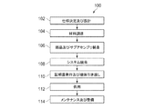
これらの図面を更に詳細に参照するに、本開示の実施形態は、図1に示す航空機製造及び整備方法100、及び図2に示す航空機200に関連して記載することができる。図1を参照するに、有利な実施形態による航空機製造及び整備方法の図が描かれている。製造前段階では、航空機製造及び整備方法100において、図2の航空機200の仕様決定及び設計102、及び材料調達104を行うことができる。
Referring to these drawings in more detail, embodiments of the present disclosure may be described in connection with the aircraft manufacturing and
製造段階では、図2の航空機200の部品及びサブアセンブリ製造106、及びシステム統合108が行われる。その後、図2の航空機200は、証明書発行及び機体引き渡し110を経て、供用112に付される。顧客が供用112している間、図2の航空機200は、日常的なメンテナンス及び整備114を行うようにスケジューリングされ、このメンテナンス及び整備114は、改修、再構成、改装、及び他のメンテナンスまたは整備を含むことができる。
In the manufacturing stage, component and
航空機製造及び整備方法100のプロセス群の各プロセスは、システムインテグレータ、サードパーティ、及び/又はオペレータによって行うことができるか、または実行することができる。これらの例では、オペレータは顧客とすることができる。この説明を進めるために、システムインテグレータとして、これらには限定されないが、何れかの数の航空機製造業者、及び航空機大手システムサブコントラクタを挙げることができ;サードパーティとして、これらには限定されないが、何れかの数のベンダー、サブコントラクタ、及びサプライヤーを挙げることができ;そしてオペレータは、航空会社、リース会社、軍隊、航空機整備機関などとすることができる。
Each process in the process group of aircraft manufacturing and
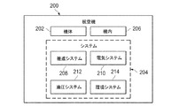
次に、図2を参照するに、有利な実施形態を実現することができる航空機の図が描かれている。この例では、航空機200は、図1の航空機製造及び整備方法100により製造され、そして複数のシステム204を搭載した機体202と、そして機内206と、を含むことができる。システム204の例として、推進システム208、電気システム210、油圧システム212、及び環境システム214のうちの1つ以上を挙げることができる。何れかの数の他のシステムを含めてもよい。航空宇宙用の例を示しているが、異なる有利な実施形態は、自動車産業のような他の産業に適用することができる。
With reference now to FIG. 2, an illustration of an aircraft is depicted in which an advantageous embodiment may be implemented. In this example,
本明細書において具体化される装置及び方法は、図1の航空機製造及び整備方法100の種々の段階のうちの少なくとも1つの段階において用いることができる。本明細書において使用されるように、「at least one of」というフレーズは、複数のアイテムを列挙して使用される場合に、列挙されるこれらのアイテムのうちの1つ以上のアイテムの異なる組み合わせを用いることができ、そして列挙されるアイテムの中の各アイテムの1つだけで済ませることができることを意味する。例えば、「at least one of item A, item B, and item C」は、例えばこれらには限定されないが、「item A(アイテムA)」または「item A and item B(アイテムA及びアイテムB)」を含むことができる。この例は更に、「item A, item B, and item C(アイテムA、アイテムB、及びアイテムC)」または「item B and item C(アイテムB及びアイテムC)」を含むことができる。
The apparatus and method embodied herein may be used in at least one of the various stages of aircraft manufacturing and
1つの例示的な例では、図1の部品及びサブアセンブリ製造106において製造される部品群またはサブアセンブリ群は、航空機200を図1において供用112している状態で製造される部品群またはサブアセンブリ群と同様の方法で組み立てる、または製造することができる。更に別の例として、多くの装置実施形態、方法実施形態、またはこれらの組み合わせは、図1の部品及びサブアセンブリ製造106、及びシステム統合108のような製造段階において利用することができる。「number(多数)」とは、アイテム群に言及する場合には、1つ以上のアイテムを指す。例えば、多数の装置実施形態とは、1つ以上の装置実施形態である。多数の装置実施形態、方法実施形態、またはこれらの組み合わせは、航空機200を供用112している間に、そして/または図1のメンテナンス及び整備114中に利用することができる。多数の異なる有利な実施形態を使用することにより、航空機200の組み立てを大幅に促進することができる、そして/または航空機200のコストを大幅に低減することができる。
In one illustrative example, the group of parts or subassemblies manufactured in the part and
例えば、異なる有利な実施形態のうちの1つ以上の実施形態を使用して、部品群の間の空間の測定を、例えばこれに限定されないが、部品及びサブアセンブリ製造106の段階、及びシステム統合108の段階において行うことができる。
For example, one or more of the different advantageous embodiments may be used to measure the space between parts, for example, but not limited to, stages of part and
異なる有利な実施形態では、多数の異なる考察事項を認識し、そして考慮に入れる。例えば、異なる有利な実施形態では、2つの部品の間の空間への接近を、これらの部品内の穴を介して行うことができることを認識し、そして考慮に入れる。例えば、部品群の間の空間には、これらの部品のうちの一方の部品内の穴を介して接近することができる。穴のサイズによっては、測定を行おうとする作業者は、治具を穴に挿入してこれらの部材の間の空間の測定を行うことができない虞がある。 Different advantageous embodiments recognize and take into account a number of different considerations. For example, in different advantageous embodiments, it is recognized and taken into account that access to the space between two parts can be made through holes in these parts. For example, the space between the component groups can be accessed through a hole in one of these components. Depending on the size of the hole, there is a possibility that an operator who wants to measure cannot measure the space between these members by inserting a jig into the hole.
異なる有利な実施形態では、手動隙間ゲージはこれらの状況における測定には不適切であることを認識し、そして考慮に入れる。この種類のゲージは、ゲージを、穴を通して収容して、空間の測定を行うことを阻止するような構成及び/又はサイズを有する。異なる有利な実施形態では、ゲージ用に十分なサイズを有する穴を拡大する、またはゲージ用に十分なサイズを有する新規の穴をドリル穿孔することは望ましくないことを認識し、そして考慮に入れる。 In a different advantageous embodiment, the manual gap gauge is recognized and taken into account as unsuitable for measurements in these situations. This type of gauge has a configuration and / or size that allows the gauge to be received through the hole to prevent taking space measurements. In different advantageous embodiments, it is recognized and taken into account that it is not desirable to enlarge a hole having a sufficient size for the gauge or to drill a new hole having a sufficient size for the gauge.
異なる有利な実施形態では、接近が制限される構造内で空間測定を行うことができる治具、及び治具を使用する方法を有することが望ましいことを認識し、そして考慮に入れる。異なる有利な実施形態では、作業者が所望の精度で測定を行うことができる治具、及び治具を使用する方法を有することが望ましいことを認識し、そして考慮に入れる。異なる有利な実施形態では、作業者が、複数位置の複数回測定を、現在のシステムと比べてより迅速に、かつより正確に行うことができるようにする方法及び装置を有することが望ましいことを認識し、そして考慮に入れる。 In different advantageous embodiments, it is recognized and taken into account that it is desirable to have a jig that can make spatial measurements in a structure with limited access, and a method of using the jig. In different advantageous embodiments, it is recognized and taken into account that it is desirable to have a jig that allows an operator to make measurements with the desired accuracy, and a method of using the jig. In different advantageous embodiments, it would be desirable to have a method and apparatus that would allow an operator to make multiple measurements at multiple locations more quickly and more accurately than with current systems. Recognize and take into account.
異なる有利な実施形態では、公知の方法を使用した部品群の間の空間の測定が、特に接近が制限される構造内では困難である、または不可能であることを認識し、そして考慮に入れる。隙間ゲージのような測定治具を配置するときに通す際に必要な余裕が不十分である可能性がある。更に、異なる有利な実施形態では、接近通路またはマンホールを、航空機アセンブリのような特定の構造物内に切断形成して、物理的接近を可能にすることは望ましくないことを認識し、そして考慮に入れる。異なる有利な実施形態では更に、複数の位置の複数の空間を、公知の方法を使用して測定することは、面倒であり、かつ多大な時間を要するプロセスであることを認識し、そして考慮に入れる。 In different advantageous embodiments, it is recognized and taken into account that the measurement of the space between parts using known methods is difficult or impossible, especially in structures where access is limited. . There is a possibility that a margin required for passing a measurement jig such as a gap gauge is insufficient. Further, in different advantageous embodiments, it is recognized and taken into account that it is not desirable to cut access passages or manholes in certain structures, such as aircraft assemblies, to allow physical access. Put in. The different advantageous embodiments further recognize and take into account that measuring multiple spaces at multiple locations using known methods is a cumbersome and time consuming process. Put in.
このように、異なる有利な実施形態は、部品群の間の空間を測定する方法及び装置を提供する。装置は、細長部材と、細長部材から延出するフランジと、そして測定システムと、を備える。細長部材の1つの端部は、第1構造内の穴を通って移動して、第1構造と第2構造との間に位置する空間に入り込むように構成される。細長部材は、フランジが穴から出て空間に入り込んだ後に突出して、フランジが穴を通って元に戻れなくなるように構成される。測定システムは、細長部材の端部の移動を測定して、第1構造と第2構造との間の空間の長さを特定するように構成される。 Thus, the different advantageous embodiments provide a method and apparatus for measuring the space between parts. The apparatus includes an elongate member, a flange extending from the elongate member, and a measurement system. One end of the elongate member is configured to move through a hole in the first structure and enter a space located between the first structure and the second structure. The elongate member is configured to project after the flange exits the hole and enters the space, so that the flange cannot pass back through the hole. The measurement system is configured to measure the movement of the end of the elongate member to determine the length of the space between the first structure and the second structure.
次に、図3を参照するに、測定環境を示すブロック図が、有利な実施形態に従って描かれている。この例では、測定環境301は測定治具313を含み、測定治具313は、アセンブリ302に装着して使用することができる。図3に示す有利な実施形態では、測定治具313は、アセンブリ302の第1部品303と第2部品311との間に存在する空間309を測定するように装着される。
With reference now to FIG. 3, a block diagram illustrating a measurement environment is depicted in accordance with an advantageous embodiment. In this example, the
測定治具313はチューブ314を含む。チューブ314は、略細長部材を含むことができる。有利な実施形態では、チューブ314は、第1端部317を含む中空チューブとすることができる。チューブ314の第1端部317は、突出位置315と後退位置316との間で前後に移動することができる。フランジ320は、チューブ314の第1端部317に近接配置することができる。フランジ320は、上側表面321と、そして下側表面322と、を含むことができる。更に、フランジ320は、厚さ323、及びフランジ直径335により特徴付けることができる。
The
測定治具313は更に、ロッド324を含むことができる。チューブ314は、中空チューブを画定する場合には、通路331を画定することができる。ロッド324は、チューブ314の通路331内に配置することにより、ロッド324が、チューブ314内を略直線移動で移動することができる。別の表現をすると、ロッド324は、チューブ314の中心を通って延びる軸に沿って移動することができる。ロッド324は従って、ロッド324の少なくとも一部が、チューブ314の第1端部317に近接するように移動することができる。有利な実施形態では、チューブ314は、ロッド324がチューブ314内に配置されない場合に後退位置316を採るように構成することができる。ロッド324をチューブ314内に配置して、ロッド324の一部が、チューブ314の第1端部317に近接配置されるようになると、チューブ314を突出位置315に移動させることができる。ロッド324をチューブ314から取り出すことにより、チューブ314を後退位置316に戻すことができる。
The measuring
有利な実施形態では、チューブ314は、外形が略円形である。しかしながら、チューブ314は、他の外形を採ることができ、曲線形状、及び例えば六角形または八角形のような角のある形状の両方の形状を採ることができる。1つの有利な実施形態では、ロッド324は、略円筒体の形状とすることができるが、ロッド324は他の形状を採ることができる。通路331は、ロッド324を収容し、かつロッド324が通路331内を移動することができるような形状に構成することができる。ロッド324は、チューブ314内を略直線方向に移動することができる。通路331は、チューブ314の第1端部317から別の開口(図示せず)にまで延在することができ、これにより、ロッド324をチューブ314に挿入することができる。
In an advantageous embodiment, the
有利な実施形態では、測定治具313は更に、突出部325を含むことができる。突出部325は、チューブ314の第1端部317をほぼ取り囲むように配置することができる。チューブ314の第1端部317は、突出部325に進入し、そして突出部325から退出することができる。収納位置326では、チューブ314の第1端部317は、突出部325内に配置される。更に、収納位置326では、フランジ320の下側表面322は、突出部325の接触面336に略平行である。チューブ314の第1端部317は、突出部325から、収納位置326から離れる方向に飛び出すことができる。1つ以上のスタビライザー351は、突出部325に近接配置することができる。スタビライザー351は、測定治具313の位置決めに使用することができる。
In an advantageous embodiment, the
突出部325は、チューブ314、第1端部317、及びフランジ320を保護する機能を提供することができる。更に、突出部325は、測定治具313を第1部品303に対して直角に配置する、または位置合わせして、測定を本明細書において説明されるように行う機能を提供することができる。更に、突出部325は、第1部品303に接触して、測定治具313の一連の測定及び移動のスタート位置を与える機能を提供することができる。
The
測定治具313は更に、測定デバイス327を含むことができる。測定デバイス327は、本明細書において詳細に説明されるように、測定を行う何れかの適切な測定装置を含むことができる。例えば、測定デバイス327は、チューブ314の直線移動を測定する測定デバイスを含むことができる。測定デバイス327は、単なる一例として、レーザ治具、マイクロメータ、またはダイヤルゲージを含むことができる。測定デバイス327は、ゼロ設定され、そして複数の測定を、測定治具313の使用中に行うように構成することができる。例えば、チューブ314の第1端部317が収納位置にある場合、測定デバイス327はゼロ位置328に位置することができる。第1測定329及び第2測定330は、測定治具313を、本明細書において詳細に説明されるように、異なる構成になるようにする場合に行うことができる。
The
有利な実施形態では、測定治具313は更に、ハウジング341を含み、このハウジング341は、チューブ314、フランジ320、ロッド324、及び測定デバイス327を含む測定治具313の構成部品群をほぼ取り囲み、そして保護することができる。
In an advantageous embodiment, the
1つの有利な実施形態では、測定治具313は、手作業治具の概略形状を採ることができる。例えば、手作業治具は、作業者によって手動で普通に使用される治具とすることができる。別の有利な実施形態では、測定治具313は、ロボットアームに接続される治具のような自動治具の形状を採ることができる。
In one advantageous embodiment, the measuring
測定治具313は、所望の測定動作をアセンブリ302に対して行う何れかの適切な治具とすることができる。1つの有利な実施形態では、アセンブリ302は、例えば航空機のアセンブリのような部品群または構造群から成るアセンブリとすることができる。1つの有利な実施形態では、測定治具313を使用して、アセンブリ302の第1部品303と第2部品311との間に存在する空間309を測定する。
The
アセンブリ302は、第1部品303と、そして第2部品311と、を含むことができる。第1部品303は、第1表面307及び第2表面308を含む表面306を有する。第2部品311は、第1表面312を有する。空間309は、第1部品303の第1表面307と第2部品311の第1表面312との間に位置する。第1部品303は更に、穴304を有することができる。穴304は直径305を有する。シム310は、図3の影線で示されている。シム310は、シム310を、第1部品303と第2部品311との間に存在する空間309に挿入することが望ましいような部材を表わす。
The
図3の測定環境301は、有利な実施形態を実現することができる態様に物理的な、または構造上の制約があることを示すために図示されているのではない。図示される構成要素群の他に、そして/または代わりに、他の構成要素群を使用してもよい。幾つかの構成要素は、不要とすることができる。また、ブロック群を提示して、幾つかの機能的構成要素を示している。これらのブロックのうちの1つ以上のブロックは、有利な実施形態において実装される場合に、組み合わせることができる、そして/または異なるブロックに分割することができる。
The
有利な実施形態では、測定治具313は、略矩形のハウジング341を含み、このハウジング341は、測定治具313の他の形状部を収容する。ハウジング341は、測定デバイス327、突出部325、及びフランジ320を収容することができる。別の有利な実施形態では、アセンブリ302は、第1部品303に対応する第1構造と、そして第2部品311に対応する第2構造と、を含む。航空機外板は、第1部品303または第1構造の一例とすることができ、そして航空機スパー(桁)は、第2部品311または第2構造の一例とすることができる。
In an advantageous embodiment, the measuring
次に、図4を参照するに、測定治具406の図が、有利な実施形態に従って描かれている。この例では、測定治具406は、図3にブロック形で図示される測定治具313の物理的形態の一例である。
With reference now to FIG. 4, a diagram of a
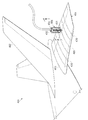
この例示的な例では、測定治具406は、航空機401の尾翼アセンブリ402に接続して使用される。航空機401は、図2の航空機200の1つの物理的形態の例である。尾翼アセンブリ402は水平尾翼403を含む。水平尾翼403は、外板404及びスパー405を含む。スパー405を破線で示して、スパー405を外板404の下方に配置することができる様子を示している。外板404及びスパー405は、この例では、図3の第1部品303及び第2部品311の一例を示している。
In this illustrative example,
製造プロセスを使用して、外板404をスパー405に取り付けることができる。測定治具406を使用して、測定を行うことができる。この例では、測定治具406は、水平尾翼403の外板404の上に配置される。測定治具406は、チューブ(図示せず)が穴を通って、外板404とスパー405との間の空間を測定するように配置することができる。図4では、直線5−5は、以下に図5に示す断面図の切断線を表している。
The
図4は更に、この例に示すように、測定治具406の形状部群のうちの幾つかの形状部を示している。測定治具406はハウジング431を含むことができ、ハウジング431は普通、測定治具406を保護するように構成される。ハウジング431は普通、測定治具406の構成部品群を取り囲む。
FIG. 4 further shows some shape portions of the shape portion group of the measuring
スイッチ432は、ハウジング431の上に配置することができる。スイッチ432は、ゼロ設定する、第1測定を行う、そして第2測定を行うように、本明細書において説明される測定作業を行うために使用することができる。
The
更に、測定治具406はプラグ433を含むことができる。プラグ433は、測定治具406との接続を可能にして、図示されていない他の付属品を差し込むことができる。従って、プラグ433に、電力接続端子、データ接続端子、またはデジタル接続端子、及び動力接続線を差し込むことができる。測定治具406への動力は、これらには限定されないが、空気圧、油圧動力、及び電気動力のような種々の形態を採ることができる。
Further, the
次に、図5を参照するに、図4に示す測定治具の図が描かれている。図5は、図4の断面線5−5に沿った断面図を示している。この図では、測定治具406は、突出部502と、チューブ503と、そしてフランジ512と、を含む。また、図4に示すように、測定治具406は、ハウジング431と、スイッチ432と、そしてプラグ433と、を含む。図5に更に示されるのは、スタビライザー561であり、これらのスタビライザー561を使用して、測定治具406を航空機外板404の上に詳細に位置決めすることができる。測定治具406のハウジング431内には、センサ563及び空気圧アクチュエータ565が収容される。センサ563は、本明細書において説明される測定デバイスを含む。空気圧アクチュエータ565は、チューブ503を、空気圧を利用して移動させることができる手段の有利な実施形態を含む。
Next, referring to FIG. 5, a diagram of the measurement jig shown in FIG. 4 is drawn. FIG. 5 shows a sectional view taken along section line 5-5 in FIG. In this figure, the
図5に示すように、フランジ512は、チューブ503の第1端部511に接続される。チューブ503の第1端部511は後退位置にある。後退位置では、フランジ512の直径によって、フランジ512が航空機外板404の穴510を通過することができるようになっている。好適には、後退位置では、フランジ512の直径は、穴510の直径よりも短いか、または穴510の直径に略等しい。航空機外板404をスパー405に対して位置決めして、空間509を外板404とスパー405との間に画定する。フランジ512は、第1部品504の第1表面506の下方を移動しているが;フランジ512は、第1部品504の第2表面507よりも上方に位置する。フランジ512は、第2部品505の第1表面508の上方に留まっている。
As shown in FIG. 5, the
図5を参照し続けると、測定治具406の物理寸法は変化し得る。有利な実施形態では、ハウジング431は、略矩形の形状、または箱状の形状を備える。ハウジング431の底面及び上面の寸法は、略等しく、かつ略正方形に設定される。代表的な幅wには所定の参照番号555が付され、そして幅wは、約1.5〜約3.0インチの範囲で変化することができる。参照番号557で示されるハウジング431の長さは、約6〜約8インチの範囲で変化することができる。
Continuing to refer to FIG. 5, the physical dimensions of the
測定治具406により得られる測定値に関して、測定値の精度も変化する可能性がある。測定治具406を使用して外板404とスパー405との間の空間を測定する有利な実施形態では、測定は、約0.005インチ未満のバラツキで行うことができる。有利な実施形態では、ソニーコーポレーション製の測定センサを使用する。測定センサは、部品番号SR118で表示されるMagnescale(登録商標)Series Linear Encoder(マグネスケールシリーズリニアエンコーダ)である。センサによって、直線移動量の測定を、電気及び/又は磁気検出を利用して行う。
Regarding the measurement value obtained by the
図5の穴510のような代表的な穴もまた、変化し得る寸法を有する。例えば、略円筒形の断面とすることができる穴510は、変化し得る直径及び長さを有することができる。穴510は更に、図5の向きに対して略垂直な方向を有するものとして描かれているが;穴510の向きは傾けてもよい。別の表現をすると、穴510の中心軸(図示せず)は、航空機外板404の第1表面506と90度以外の或る角度をなすように設定することができる。穴510は、ファスナーまたは他の構造を、穴を通して収容するようにドリル穿孔して形成されている穴とすることができる。有利な実施形態では、穴510は、約0.125〜約0.5インチの範囲の図3の穴径305により特徴付けられる。チューブ503は、チューブ503を穴510に挿通することができるような直径を含むことができるので、チューブ503の直径は、穴510に関して説明した通りに変化することができる。突出部502は、種々の外形形状を採ることができる。有利な実施形態では、突出部502は略円筒形である。突出部502は、記号「d」で示される直径559を含むことができ、この直径559によって、突出部502が、穴510に入り込むのを阻止している。有利な実施形態では、突出部502は、約1〜約3インチの範囲の直径559を含む。
Exemplary holes, such as
次に、図6,7,及び8を参照するに、測定治具406の一部を示す幾つかの図が、有利な実施形態に従って描かれている。図6,7,及び8は、空間606を測定するために使用される異なる位置にある測定治具406の一部を示している。
Referring now to FIGS. 6, 7, and 8, several views illustrating portions of the
まず、図6を参照するに、ハウジング431、突出部502、センサ563、及び空気圧アクチュエータ565のような、測定治具406の幾つかの構造は、測定が行われる様子を分かり易く示すために図示されていない。測定治具406の一部または或る部分のみを描いて、測定が行われる様子を示している。図6,7,及び8は更に、航空機の外板404及びスパー405に対応する第1部品604、第2部品605、及び空間606のような構造を描いている。
First, referring to FIG. 6, several structures of the
図示のように、測定治具406内のチューブ601は、穴630を通って空間606に入り込むように延出している。チューブ601の第1端部602は、第1部品604の第1表面607を通り過ぎている。ロッド611は、チューブ601の通路612に挿入されている。ロッド611は、ロッド611の一部が、チューブ601の第1端部602に近接配置されるように挿入されている。ロッド611をこのように位置決めすることにより、チューブ601の第1端部602が後退位置から突出位置に移動するようになる。
As illustrated, the
スロット610によって、第1端部602を突出位置に移動させることができる。突出位置では、フランジ603の直径はこの時点で、穴630の直径よりも大きくなっている。突出位置では、フランジ603は、穴630を通り抜けることができない。図6では、フランジ603が、第1部品604または第2部品605の表面に未だ全く接触していないことにも注目されたい。図6に示すように、チューブ601の第1端部602は、第1部品604と第2部品605との間に位置している。空間606は、第1部品604の第2表面608と第2部品605の第1表面609との間に在る。図6に示す位置では、フランジ603の上側表面621及び下側表面622は、第1部品604または第2部品605に接触していない。
The
次に、図7を参照するに、別の位置にある測定治具を示す図が、有利な実施形態に従って描かれている。この例示的な例では、測定治具406のチューブ601は、図6におけるよりも更に突出している。チューブ601は、第1部品604の第1表面607、及び第1部品604の第2表面608よりもずっと下方に移動している。チューブ601の移動は、穴630を通過する移動を含む。ロッド611(図示せず)は通路612内に収まったままである。第1端部602のフランジ603はこの時点で、第2部品605に接触している。更に具体的には、フランジ603の下側表面622は、第2部品605の第1表面609に接触している。フランジ603の上側表面621は、表面に接触していない。図7の位置に移動する際、チューブ601は、突出位置から完全に離れたところまで移動していないので、スロット610は、図6のこれらのスロットの位置から動いていない。この時点で、図3の第1測定329のような第1測定が行われる。
With reference now to FIG. 7, a diagram illustrating a measurement fixture in another position is depicted in accordance with an advantageous embodiment. In this illustrative example, the
次に、図8を参照するに、別の位置にある測定治具の図が、有利な実施形態に従って描かれている。図示のように、測定治具406は、図7から位置が変わっている。チューブ601は、第2部品605から離れる方向に移動しており、そしてこの時点では、第1部品604に接触している。更に具体的には、フランジ603の上側表面621は、第1部品604の第2表面608に接触している。フランジ603の下側表面622は、表面には全く接触していない。フランジ603は、第2部品605の第1表面609よりも上方に位置している。図7の位置から図8の位置に移動する際、フランジ603は、空間606を通って、第1部品604に向かう方向に更に移動している。チューブ601の移動は、穴630を通過する移動を含む。この位置では、図3の第2測定330のような測定を行うことができる。図8では、突出位置にあるフランジ603が、穴630を自由に通過することができないので、フランジ603は第1部品604に接触するようになることに注目されたい。従って、チューブ601が、チューブの図7の位置からチューブの図8の位置に引き上げられると、フランジ603が第1部品604に接触するようになり、そしてチューブ601が上方の垂直方向に(図8の向きに対して)更に移動するのが抑制されている。
With reference now to FIG. 8, a diagram of a measurement fixture in another position is depicted in accordance with an advantageous embodiment. As illustrated, the position of the
チューブ601を図8の位置から引き抜こうとする場合、チューブ601は後退位置に移動させることができる。これは、ロッド611をチューブ601から引き抜くことにより行うことができる。ロッド611を引き抜くことにより、チューブ601をチューブの元の状態または静止状態に、すなわち後退位置に変化させる、または遷移させることができる。スロット群610は、この遷移が可能になるように作動する。後退位置では、フランジ603の直径は、直径によって、フランジ603及びチューブ601が、第1部品604を通り過ぎて移動することができるような大きさになる。
When the
図5〜8に関する上の説明では、チューブ601の第1端部は、チューブが、静止状態にある、またはチューブの元の状態になっているときに、後退位置にあるものとして説明してきた。チューブ601は、ロッド611をチューブ601に挿入することにより突出位置に移動し、そして次に、チューブ601は、ロッド611をチューブ601から取り出すことにより後退位置に移動する。他の構成を用いることができることに留意されたい。例えば、チューブ601は、静止状態にあるときに突出位置に位置するように構成することができる。この例では、チューブ601は、摺動スリーブのような圧迫部材(図示せず)をチューブ601の第1端部602の外部位置を覆うように配置することにより、後退位置に移動させることができる。圧迫部材は、圧迫部材でチューブ601の第1端部602を挟んで圧迫して、第1端部602を移動させることができるような直径を有するように構成することができる。
In the above description with respect to FIGS. 5-8, the first end of the
図8を参照し続けると、有利な実施形態に従って行われる測定は、第1測定805及び第2測定807として図示される。フランジ603が図7に示す位置にあるときに行われる第1測定805による測定値は、第1部品604の第1表面607と第2部品605の第1表面609との間の距離を表わす。第1測定805は、チューブ601が第1表面607から第1表面609に移動する直線移動量の測定として、図5のセンサ563によって行うことができる。フランジ603が図8に示す位置にあるときに行われる第2測定807による測定値は、第2部品605の第1表面609と第1部品604の第2表面608との間の距離を表わす。第2測定807は、チューブ601が第1表面609から第2表面608に移動する直線移動量の測定として、図5のセンサ563によって行うことができる。第1測定805及び第2測定807の精度は、フランジ603が図3におけるような収納位置326にあり、かつ突出部325が図3におけるようなゼロ位置328にあるときにチューブ601をゼロ設定することにより向上させることができる。測定治具406をゼロ設定するステップについて、本明細書では、以下の図10に説明される測定方法に関連して詳細に説明する。
With continued reference to FIG. 8, measurements made in accordance with an advantageous embodiment are illustrated as
第1表面609と第2表面608との間の距離を表わす空間809は、第2測定値807を第1測定値805から減算するとともに、更に、フランジ603の図3におけるような厚さ323を考慮に入れることにより測定することができる。空間809を測定する際、第2測定値807は、フランジ603により制約されるチューブ601の移動量の影響を受けるので、厚さ323を考慮に入れる必要がある。図8では、フランジ603の上側表面621が第2表面608に接触するのに対し、図7では、フランジ603の下側表面622が第1表面609に接触する。フランジ603の図3におけるような厚さ323は既知の量とすることができる。
A
図5〜8の図は、1つの有利な実施形態を示しており、測定治具を装着することができる態様、または測定を行うことができる態様を限定するために示しているのではない。図6,7,及び8に示すような、測定治具406における移動の順番は、1つの有利な実施形態の例示に過ぎない。図8の測定は、これらの測定が、測定治具406の移動に追従しているので効率的に行われ、従ってどのようにして測定を効率的に行うことができるかについて表わしている例である。
The illustrations of FIGS. 5-8 illustrate one advantageous embodiment and are not intended to limit the manner in which the measurement fixture can be mounted or the manner in which measurements can be performed. The order of movement in the measuring
例えば、航空機水平尾翼の複数の穴を測定する場合、測定治具は、穴から穴へ移動し、そして異なる穴に入り込み、そして異なる穴から出てくる。しかしながら、別の例では、1つの測定は、測定値が、第2部品605の第1表面609から第1部品604の第2表面608へのチューブ601の移動量を含むように行うこともできる。別の実施形態では、1つの測定は、第1部品604の第2表面608から第2部品605の第1表面609へのチューブ601の移動量を含むように行うことができる。他の種類の測定を行うこともできる。
For example, when measuring multiple holes in an aircraft horizontal tail, the measurement jig moves from hole to hole, enters different holes, and exits from different holes. However, in another example, one measurement may be made such that the measurement includes the amount of movement of the
図6,7,及び8の有利な実施形態についての説明では、チューブ601の第1端部602の過渡的な移動は、スロット群610を、チューブ601の第1端部602に配置することにより容易になる。チューブ601は、複数のスロット610を有するように形成することができる。1つの有利な実施形態では、スロット群610は、チューブ601の切り欠き部を含み、これらの切り欠き部は略垂直方向に延びている。スロット群610の数、サイズ、及び配置は、後退位置から突出位置に、そして後退位置に戻るチューブ601の第1端部602の過渡的な移動を容易にすることができるように選択することができる。
In the description of the advantageous embodiment of FIGS. 6, 7, and 8, the transient movement of the
チューブ601及び測定治具406は普通、本明細書において説明される機能を可能にする何れの材料によっても構成することができる。一般的に、金属及び金属合金は、説明される測定治具406の構造に関して許容可能な材料となる。アルミニウム合金は、測定治具406及びチューブ601を構成することができる材料の一例である。使用することができる金属の他の例として、スチール合金、ニッケルスチール合金、チタン、及びチタン合金を挙げることができる。プラスチック、セラミック、及び複合材のような他の材料を使用することもできる。
次に、図9を参照するに、測定プロセスのフローチャートの図が、1つの有利な実施形態に従って描かれている。プロセスは、参照番号900で一括指示され、そして第1部品と第2部品との間の空間を測定するプロセスとすることができる。プロセスの1つの例では、図4に示す尾翼アセンブリの水平尾翼の外板とスパーとの間の空間を測定することができる。方法は、例えば図3のアセンブリ302に相互接続される測定治具313を使用して行うことができ、そして以下の参照番号は、これらの図の構造群及び形状部群を指している。
Referring now to FIG. 9, a flowchart of a measurement process is depicted in accordance with one advantageous embodiment. The process can be a process that is collectively indicated by the
プロセス900は、チューブ314の第1端部317を後退位置316に移動させる(操作901)ことから始めることができる。1つの有利な実施形態では、チューブ314の第1端部317を、何もしないで後退位置316に置くことができる。他の実施形態では、複数ステップを行って、第1端部317を後退位置316に移動させる必要がある。1つの例では、圧迫部材またはスリーブが摺動して第1端部317に接近することにより、第1端部317を後退位置316に移動させる。
次のステップでは、チューブ314の第1端部317を、アセンブリ302の第1部品303の穴304に挿入する(操作902)。チューブ314の第1端部317に接続されるフランジ320は、後退位置316において、穴304を通過するようなサイズになっている。1つの有利な実施形態では、穴304はファスナー穴であり、このファスナー穴は、第1部品に設けるか、または形成される。1つの例として、第1部品303は、航空機外板を含むことができ、そして穴304は、外板に形成されるファスナー穴を含む。
In the next step, the
次のステップでは、チューブ314を、フランジ320の下側表面が第2部品311の第1表面312に接触するまで、第1部品303の穴304を通って降下または移動させる(操作903)。1つの有利な実施形態では、第2部品311はスパー群405を含むことができ、これらのスパー405に、航空機外板404を取り付けることになる。第1測定329をこの時点で行うことができる(操作904)。
In the next step, the
次のステップでは、チューブ314の第1端部317を後退位置316から突出位置315に移動させる(操作905)。後退位置316から突出位置315への移動は、ロッド324をチューブ314の通路331に挿入することにより行うことができる。ロッド324が、チューブ314の第1端部317に近接する位置に移動すると、チューブ314の第1端部317が突出位置315に移動する。
In the next step, the
次のステップでは、チューブ314の第1端部317を、フランジ320の上側表面321が第1部品303の第2表面308に接触するまで、上昇または移動させる(操作906)。突出位置315では、フランジ320は、穴304よりも大きいフランジ直径335を有しているので、フランジ320が穴304を通過することが阻止される。第2測定330をこの時点で行うことができる(操作907)。
In the next step, the
次のステップでは、第1部品303と第2部品311との間の空間309を測定する(操作908)。空間309は、第2部品311の第1表面312と第1部品303の第2表面308との間の距離を含む。1つの有利な実施形態では、空間309の測定は、第2測定値330を、フランジ320の厚さ323を考慮に入れて第1測定値329から差し引いたときの差である。
In the next step, the
第1測定(操作904)及び第2測定(操作907)におけるような測定は、公知の測定デバイスを用いて行うことができる。公知の測定デバイスは、レーザ測定器、直線移動測定装置、ダイヤルゲージ、及びマイクロメータを含む。1つの測定値は、例えば位置指示値だけでなくチューブの移動量測定値の両方を含むことができる。 Measurements such as those in the first measurement (operation 904) and the second measurement (operation 907) can be performed using a known measurement device. Known measuring devices include laser measuring instruments, linear movement measuring devices, dial gauges, and micrometers. One measured value can include, for example, both a measured value of tube movement as well as a position indication value.
次のステップでは、チューブ314の第1端部317を後退位置316に移動させる(操作909)。1つの有利な実施形態では、操作909は、ロッド324をチューブ314の通路331から取り出すことにより行うことができる。これにより、チューブ314の第1端部317を、後退位置316であるチューブの弛緩状態または元の状態に戻すことができる。後退位置316では、フランジ320は、穴304の直径305よりも小さいフランジ直径335を有することになり、そしてチューブ314を、穴304を通して引き抜くことができる。
In the next step, the
次のステップでは、上記一連の操作を他の穴位置に対して繰り返すことができる(操作910)。外板404とスパー群405との間の空間の測定を行う有利な実施形態では、一連の操作を、外板404内の複数の穴に対して繰り返すことができる。
In the next step, the above series of operations can be repeated for other hole positions (operation 910). In an advantageous embodiment for measuring the space between the
このようにして、外板と下に位置するスパー、または一連のスパーとの間の空間のマッピングを行うことができる。マッピングは、複数の穴位置の各穴位置で測定される間隔を表わす。間隔情報を更に、コントローラ、メモリ、または他のコンピュータ支援装置に転送して間隔情報を、図13を参照しながら本明細書において詳細に説明されるように、記録し、そして処理することができる。次に、間隔情報を使用して、空間309に挿入されるシム310を設計し、そして適合させることができる。
In this way, the space can be mapped between the skin and the underlying spar or series of spar. The mapping represents an interval measured at each hole position of a plurality of hole positions. The interval information can be further transferred to a controller, memory, or other computer-aided device so that the interval information can be recorded and processed as described in detail herein with reference to FIG. . The spacing information can then be used to design and adapt a
次に、図10を参照するに、測定デバイスをゼロ設定するプロセスのフローチャートの図が描かれている。図10の方法は、この場合も同じように、図3の測定治具313及びアセンブリ302に関連して行うことができ、そして図3の形状部に関連して記載される。プロセスは、参照番号1000で一括指示される。図10のステップ群は、図9に示すステップ群に関連して行うことができる。1つの操作では、チューブ314の第1端部317を突出部325の収納位置326に収納する(操作1001)。
Referring now to FIG. 10, a flowchart diagram of a process for zeroing the measurement device is depicted. The method of FIG. 10 can again be performed in connection with the
次に、突出部325を、突出部325の接触面336が第1部品303の第1表面307に接触するまで降下させる(操作1002)。その後、測定デバイス327をゼロ位置328にゼロ設定し(操作1003)、プロセスはその後、終了する。図10のステップ群の有利な実施形態では、測定治具313の突出部325を、航空機外板の上側表面に接触するように配置する。この場合、フランジ320の下側表面322は、収納位置326の突出部325の接触面336に略位置合わせされる。測定装置を位置でゼロ設定する。
Next, the
次に、図11を参照するに、部品群の間の空間を測定するプロセスのフローチャートの図が描かれている。プロセスは、参照番号1100で一括指示される。この場合も同じように、ステップ群は、図3の構成要素群に関連して記載される。まず、チューブ314を、穴304を通って、フランジ320の下側表面322が第2部品311の第1表面312に接触するまで降下させる(操作1101)。この位置では、測定デバイス327をゼロ設定する(操作1102)。次に、チューブ314を、フランジ320の上側表面321が第1部品303の第2表面308に接触するまで上昇させる(操作1103)。測定は、チューブ314が、ステップ1103の位置にあって、フランジ320の上側表面321が第1部品303の第2表面308に接触している状態で行い(操作1104)、プロセスはその後、終了する。
Referring now to FIG. 11, a flowchart diagram of a process for measuring the space between parts groups is depicted. The process is indicated collectively with
次に、図12を参照するに、部品群の間の空間のマップを作成するプロセスのフローチャートの図が描かれている。フローチャートは、この場合も同じように、図3において説明される構成要素群に関連して記載される。プロセスは、参照番号1200で一括指示される。プロセスの1つのステップでは、測定治具313を第1穴の位置に位置決めする(操作1201)。第1穴位置における空間を測定する(操作1202)。この空間は、第1部品303と第2部品311との間の空間、例えば航空機アセンブリの航空機外板とスパーとの間の間隔を表わす。空間をデータベースに記録する(操作1203)。次のステップでは、測定治具313を第2穴位置に位置決めする(操作1204)。空間を第2穴の位置で測定する(操作1205)。空間は、データベースに記録することができる(操作1206)。次のステップでは、間隔のマップを作成し(操作1207)、プロセスはその後、終了する。間隔のマップをこのようにして、多数の穴に対して作成することができることを理解されたい。
Referring now to FIG. 12, a flowchart diagram of a process for creating a map of the space between parts is depicted. The flow chart is again described in connection with the group of components illustrated in FIG. The process is indicated collectively by
異なる図示の実施形態におけるフローチャート及びブロック図は、装置、方法、及びコンピュータプログラム製品の幾つかの可能な実施形態のアーキテクチャ、機能、及び操作を示している。この点に関して、これらのフローチャートまたはブロック図における各ブロックは、モジュール、セグメント、操作を表わす、またはコンピュータ可用または可読プログラムコードのうち、指定機能または機能群を実行する1つ以上の実行可能命令を含む部分を表わすことができる。ブロック群のうちの幾つかのブロックは、ヒューマンオペレータ、マシン、または他のタイプのオペレータによって実行することができる。 The flowcharts and block diagrams in the different illustrated embodiments illustrate the architecture, functionality, and operation of some possible embodiments of apparatus, methods and computer program products. In this regard, each block in these flowcharts or block diagrams includes one or more executable instructions that represent a module, segment, operation, or that perform a specified function or group of computer-readable or readable program code. A part can be represented. Some blocks in the group of blocks can be executed by human operators, machines, or other types of operators.
幾つかの別の実施形態では、ブロックに記述される機能または機能群は、これらの図に記載される順番とは異なる順番で行うことができる。例えば、或る場合には、連続して示される2つのブロックは、略同時に実行することができる、またはこれらのブロックは、実行される機能によって異なるが、逆の順番で実行してもよい場合がある。 In some alternative embodiments, the functions or groups of functions described in the blocks can be performed in a different order than the order described in these figures. For example, in some cases, two blocks shown in succession can be executed substantially simultaneously, or these blocks may be executed in reverse order, depending on the function being performed. There is.
本明細書において説明される本開示の有利な実施形態では、測定治具が提供され、測定治具は、作業者が第1部品と第2部品との間の空間の測定を行うことができるように位置決めされ、この場合、空間への接近は制約を受ける、または制限される。測定治具は、例えばチューブ、突出部、フランジ、ロッド、及び/又は測定デバイスを含むことができる。チューブ、突出部、ロッド、及び/又は測定デバイスは、ハウジングに収容することができる。チューブは第1端部を含み、そしてチューブの第1端部は、後退位置と突出位置との間を移動するように構成される。チューブは更に、第1端部に近接する少なくとも1つの切り欠き部を含むことができる。切り欠き部は、チューブに沿って長さ方向に形成される多数のスロットを含むことができる。フランジは、第1端部に近接して配置することができる。フランジは、上側表面及び下側表面を有することができ、そしてフランジは、或る厚さによって特徴付けることができる。フランジ及び第1端部は、第1部品の穴を、第1端部が後退位置にあるときに通過するように構成することができる。更に、フランジは、フランジの上側表面が第1部品の下側表面に、第1端部が突出位置にあるときに接触するように構成することができる。ロッドは、チューブ内を移動するように配置することができる。ロッドを収容するために、チューブは中空とすることができ、かつ1つの通路によって特徴付けることができる。ロッドは、チューブを突出位置に、ロッドがチューブに、第1端部に近接して挿入されるときに移動させるように構成することができる。測定デバイスは、チューブの移動を記録するように構成することができる。 In an advantageous embodiment of the present disclosure described herein, a measurement jig is provided that allows an operator to measure a space between a first part and a second part. In this case, access to the space is constrained or limited. The measurement jig can include, for example, a tube, a protrusion, a flange, a rod, and / or a measurement device. The tube, protrusion, rod, and / or measurement device can be housed in the housing. The tube includes a first end, and the first end of the tube is configured to move between a retracted position and a protruding position. The tube can further include at least one notch proximate the first end. The cutout can include a number of slots formed longitudinally along the tube. The flange can be disposed proximate to the first end. The flange can have an upper surface and a lower surface, and the flange can be characterized by a certain thickness. The flange and the first end can be configured to pass through the hole in the first component when the first end is in the retracted position. Further, the flange can be configured to contact when the upper surface of the flange is in contact with the lower surface of the first part and the first end is in the protruding position. The rod can be arranged to move within the tube. To accommodate the rod, the tube can be hollow and can be characterized by a single passage. The rod can be configured to move the tube into a protruding position when the rod is inserted into the tube proximate the first end. The measuring device can be configured to record the movement of the tube.
本明細書において説明される本開示の有利な実施形態では、作業者は、構造群の間の空間の高精度な測定を迅速かつ効率的に行うことができる。航空機のアセンブリでは、本明細書において説明される実施形態によって作業者は測定治具を、従来の測定デバイスが接近することができなかった空間に位置決めすることができる。測定治具が薄くなり、かつ測定治具のチューブが直線移動することによって、チューブを、ファスナー穴のような小さな開口に進入させ、そして開口から退出させることができる。測定治具は、従来の測定システムを配置することができなかった箇所に位置決めすることができる。測定治具のフランジを更に、後退位置から突出位置に移動させて、フランジ及びチューブを位置決めして測定を行うことができるようにする。更に、測定治具を、例えば空気圧作動により自動的に移動させると、測定を迅速に、かつ素早く行うことができる。 In an advantageous embodiment of the present disclosure described herein, an operator can quickly and efficiently make a highly accurate measurement of the space between structures. In an aircraft assembly, the embodiments described herein allow an operator to position a measurement fixture in a space that a conventional measurement device could not access. When the measuring jig is thinned and the tube of the measuring jig is linearly moved, the tube can enter and exit from a small opening such as a fastener hole. The measurement jig can be positioned at a location where the conventional measurement system could not be arranged. Further, the flange of the measurement jig is moved from the retracted position to the protruding position, and the flange and the tube are positioned so that the measurement can be performed. Furthermore, when the measuring jig is automatically moved by, for example, pneumatic operation, the measurement can be performed quickly and quickly.
異なる有利な実施形態についての説明を行って、図示及び記述を行ってきたが、説明を網羅しようと意図しているのではない、または説明を開示される形態の実施形態に限定しようと意図しているのではない。多くの変形及び変更が可能であることは、この技術分野の当業者には明らかであろう。更に、異なる有利な実施形態は、他の有利な実施形態とは異なる利点を提供することができる。選択された実施形態または実施形態群は、これらの実施形態、実際の応用形態の原理を最も分かり易く説明するために、そしてこの技術分野の当業者が、想定される特定の使用に適合するように種々の変更が加えられる種々の実施形態の開示内容を理解することができるように選択され、そして記載されている。 While the different advantageous embodiments have been described and illustrated and described, they are not intended to be exhaustive or are intended to limit the description to the disclosed embodiments. It is not. Many variations and modifications will be apparent to those skilled in the art. Furthermore, the different advantageous embodiments may provide different advantages than the other advantageous embodiments. Selected embodiments or groups of embodiments are intended to best explain the principles of these embodiments, practical applications, and to allow those skilled in the art to adapt to the particular use envisioned. Have been chosen and described so that the disclosure of the various embodiments in which various modifications may be made may be understood.
Claims (15)
細長部材から延出するフランジであって、フランジが穴を通り抜けて戻ることができないように、フランジが第1構造の穴から出た後に、細長部材が突出するように構成される、フランジと、
細長部材の端部の移動量を測定して、第1構造と第2構造との間の空間の長さを同定するように構成される、測定システムと
を備える、装置。 An elongate member, wherein the end of the elongate member is configured to move through a hole in the first structure and enter a space located between the first structure and the second structure. When,
A flange extending from the elongated member, the flange configured to protrude after the flange has exited the hole in the first structure so that the flange cannot pass back through the hole;
An apparatus comprising: a measurement system configured to measure the amount of movement of the end of the elongate member to identify the length of the space between the first structure and the second structure.
第1端部を有するチューブであって、チューブの第1端部が、後退位置と突出位置との間を移動するように構成され、チューブが、第1端部に近接する少なくとも1つの切り欠き部を有する、チューブと、
第1端部に近接配置されるフランジであって、フランジが、上側表面及び下側表面を有し、フランジが或る厚さによって特徴付けられ、フランジ及び第1端部が、第1端部が後退位置にあるときに第1部品の穴を通過するように構成され、フランジが、第1端部が突出位置にあるときにフランジの上側表面が第1部品の下側表面に接触するように構成される、フランジと、
チューブ内に移動可能に配置されるロッドであって、ロッドがチューブに第1端部に近接して挿入されるときにチューブを突出位置に移動させるように構成される、ロッドと、
チューブの移動量を記録するように構成される測定デバイスと
を備える、装置。 A device for measuring space,
A tube having a first end, wherein the first end of the tube is configured to move between a retracted position and a protruding position, the tube being at least one notch proximate to the first end. A tube having a portion;
A flange disposed proximate to a first end, wherein the flange has an upper surface and a lower surface, the flange is characterized by a thickness, and the flange and the first end are the first end. Is configured to pass through the hole in the first part when in the retracted position, so that the flange contacts the lower surface of the first part when the first end is in the protruding position. Composed of a flange, and
A rod movably disposed within the tube, the rod configured to move the tube to a protruding position when the rod is inserted into the tube proximate the first end; and
And a measuring device configured to record the amount of movement of the tube.
チューブの上に配置されるフランジの下側表面が第2部品の第1表面に接触するまで、チューブの第1端部を第1部品の穴に挿通させるステップと、
第1部品の第1表面と第2部品の第1表面との間の距離の測定を第1測定として行うステップと、
チューブの上に配置されるフランジの上側表面が、第1部品の第2表面に接触するまで、チューブを上昇させるステップと、
第1部品の第1表面と第1部品の第2表面との間の距離の測定を第2測定として行うステップと、
第1部品の第2表面と第2部品の第1表面との間の空間を測定するステップと
を含む、方法。 A method for measuring a space between a first part and a second part,
Inserting the first end of the tube through the hole in the first part until the lower surface of the flange disposed on the tube contacts the first surface of the second part;
Measuring the distance between the first surface of the first part and the first surface of the second part as a first measurement;
Raising the tube until the upper surface of the flange disposed on the tube contacts the second surface of the first part;
Measuring the distance between the first surface of the first part and the second surface of the first part as a second measurement;
Measuring the space between the second surface of the first part and the first surface of the second part.
Applications Claiming Priority (2)
| Application Number | Priority Date | Filing Date | Title |
|---|---|---|---|
| US13/169,945 US8336222B1 (en) | 2011-06-27 | 2011-06-27 | Method and apparatus for measuring spaces with limited access |
| US13/169,945 | 2011-06-27 |
Publications (3)
| Publication Number | Publication Date |
|---|---|
| JP2013011602A true JP2013011602A (en) | 2013-01-17 |
| JP2013011602A5 JP2013011602A5 (en) | 2015-07-16 |
| JP6397605B2 JP6397605B2 (en) | 2018-09-26 |
Family
ID=46639281
Family Applications (1)
| Application Number | Title | Priority Date | Filing Date |
|---|---|---|---|
| JP2012136830A Active JP6397605B2 (en) | 2011-06-27 | 2012-06-18 | Method and apparatus for measuring space with limited access |
Country Status (4)
| Country | Link |
|---|---|
| US (1) | US8336222B1 (en) |
| EP (1) | EP2541190B1 (en) |
| JP (1) | JP6397605B2 (en) |
| CA (1) | CA2775866C (en) |
Cited By (2)
| Publication number | Priority date | Publication date | Assignee | Title |
|---|---|---|---|---|
| JP2017087186A (en) * | 2015-11-16 | 2017-05-25 | 株式会社Screenホールディングス | Coating device, manufacturing apparatus and measuring method |
| KR101949085B1 (en) | 2018-06-21 | 2019-02-15 | 신윤은 | Method of measuring the front inner diameter length of a sheet carrier |
Families Citing this family (12)
| Publication number | Priority date | Publication date | Assignee | Title |
|---|---|---|---|---|
| CN104482840B (en) * | 2014-11-20 | 2017-09-19 | 航天海鹰(镇江)特种材料有限公司 | Force application apparatus and detection method for detecting Composite Panels patch die clearance |
| US10168136B2 (en) | 2016-03-22 | 2019-01-01 | Rolls-Royce Corporation | Clearance gage |
| US10286556B2 (en) * | 2016-10-16 | 2019-05-14 | The Boeing Company | Method and apparatus for compliant robotic end-effector |
| US10330453B2 (en) | 2017-03-29 | 2019-06-25 | Lockheed Martin Corporation | Wireless fastener grip gauge |
| CN109798828B (en) * | 2017-11-17 | 2022-11-22 | 上海仪器仪表研究所 | Flange positioning instrument |
| CN109059728B (en) * | 2018-08-02 | 2023-09-22 | 江苏理工学院 | Circumferential hole position size error detection tool |
| CN109579675B (en) * | 2019-01-09 | 2023-09-08 | 山东太古飞机工程有限公司 | Auxiliary measurement tool for measuring concave-convex degree of aircraft skin |
| CN111238345B (en) * | 2020-03-16 | 2021-08-17 | 长沙五量汽车配件有限公司 | Rod end face blind hole depth detection method |
| CN111238346B (en) * | 2020-03-16 | 2022-02-25 | 江山跟政科技有限公司 | Workpiece surface pit inspection method |
| CN111238347B (en) * | 2020-03-16 | 2021-07-27 | 常州市鑫亿莱精密机械有限公司 | Workpiece surface pit inspection device |
| CN113074613A (en) * | 2020-03-16 | 2021-07-06 | 江山市发发科技有限公司 | Rod end face blind hole depth detection device |
| US11920915B2 (en) * | 2021-04-07 | 2024-03-05 | The Boeing Company | Non-contact measurement for interface gaps |
Citations (7)
| Publication number | Priority date | Publication date | Assignee | Title |
|---|---|---|---|---|
| US2490364A (en) * | 1948-02-27 | 1949-12-06 | Herman H Livingston | Bone pin |
| JPS5036117B1 (en) * | 1970-07-08 | 1975-11-21 | ||
| JPS59103203U (en) * | 1982-12-27 | 1984-07-11 | 株式会社東芝 | measuring device |
| JPS6015607U (en) * | 1983-07-11 | 1985-02-02 | トヨタ自動車株式会社 | Gap measuring device |
| JPS60137302U (en) * | 1984-02-24 | 1985-09-11 | 多摩川精機株式会社 | Hole dimension measuring device |
| JP2007111538A (en) * | 2001-06-14 | 2007-05-10 | Intrinsic Therapeutics Inc | Intervertebral diagnostic and manipulation device |
| JP2010046307A (en) * | 2008-08-22 | 2010-03-04 | Japan Medical Materials Corp | Bone fixture |
Family Cites Families (15)
| Publication number | Priority date | Publication date | Assignee | Title |
|---|---|---|---|---|
| US2650435A (en) * | 1950-07-10 | 1953-09-01 | Lloyd L Kidd | Multipurpose depth gauge |
| US2888751A (en) * | 1956-03-05 | 1959-06-02 | Hamilton Watch Co | Gauge attachment |
| US2910781A (en) * | 1957-03-29 | 1959-11-03 | Starrett L S Co | Dial hole gauge |
| US4033043A (en) * | 1975-07-09 | 1977-07-05 | Cunningham Frank W | Gauge for measuring length of an opening |
| US4837615A (en) | 1987-09-29 | 1989-06-06 | Textron Inc. | Gap measuring apparatus |
| US4848137A (en) | 1988-03-23 | 1989-07-18 | The Boeing Company | Automated shim manufacturing system |
| US4930226A (en) * | 1989-05-22 | 1990-06-05 | Deere & Company | Sensor adjustment gauge |
| US5013318A (en) * | 1990-07-31 | 1991-05-07 | Special Devices Incorporated | Medical instrument for measuring depth of fastener hold in bone |
| US5497560A (en) * | 1995-01-27 | 1996-03-12 | Pasquerella; David | Depth finder |
| US7717961B2 (en) | 1999-08-18 | 2010-05-18 | Intrinsic Therapeutics, Inc. | Apparatus delivery in an intervertebral disc |
| US7216441B2 (en) * | 2005-07-29 | 2007-05-15 | Robert Alan Batora | Apparatus for measuring step height or depth against another surface |
| US7730789B2 (en) | 2006-11-01 | 2010-06-08 | Boeing Management Company | Device and method for measuring a gap between members of a structure for manufacture of a shim |
| US7607238B2 (en) * | 2006-11-07 | 2009-10-27 | Eidosmed Llc | Digital depth gauge |
| US20090005786A1 (en) | 2007-06-28 | 2009-01-01 | Stryker Trauma Gmbh | Bone hole measuring device |
| US7913411B2 (en) * | 2008-03-21 | 2011-03-29 | Dorsey Metrology International | Digital bore gage handle |
-
2011
- 2011-06-27 US US13/169,945 patent/US8336222B1/en active Active
-
2012
- 2012-04-30 CA CA2775866A patent/CA2775866C/en active Active
- 2012-06-12 EP EP12171644.3A patent/EP2541190B1/en active Active
- 2012-06-18 JP JP2012136830A patent/JP6397605B2/en active Active
Patent Citations (7)
| Publication number | Priority date | Publication date | Assignee | Title |
|---|---|---|---|---|
| US2490364A (en) * | 1948-02-27 | 1949-12-06 | Herman H Livingston | Bone pin |
| JPS5036117B1 (en) * | 1970-07-08 | 1975-11-21 | ||
| JPS59103203U (en) * | 1982-12-27 | 1984-07-11 | 株式会社東芝 | measuring device |
| JPS6015607U (en) * | 1983-07-11 | 1985-02-02 | トヨタ自動車株式会社 | Gap measuring device |
| JPS60137302U (en) * | 1984-02-24 | 1985-09-11 | 多摩川精機株式会社 | Hole dimension measuring device |
| JP2007111538A (en) * | 2001-06-14 | 2007-05-10 | Intrinsic Therapeutics Inc | Intervertebral diagnostic and manipulation device |
| JP2010046307A (en) * | 2008-08-22 | 2010-03-04 | Japan Medical Materials Corp | Bone fixture |
Cited By (3)
| Publication number | Priority date | Publication date | Assignee | Title |
|---|---|---|---|---|
| JP2017087186A (en) * | 2015-11-16 | 2017-05-25 | 株式会社Screenホールディングス | Coating device, manufacturing apparatus and measuring method |
| WO2017086078A1 (en) * | 2015-11-16 | 2017-05-26 | 株式会社Screenホールディングス | Coating device, manufacturing device, and measurement method |
| KR101949085B1 (en) | 2018-06-21 | 2019-02-15 | 신윤은 | Method of measuring the front inner diameter length of a sheet carrier |
Also Published As
| Publication number | Publication date |
|---|---|
| JP6397605B2 (en) | 2018-09-26 |
| CA2775866C (en) | 2015-07-14 |
| US20120324749A1 (en) | 2012-12-27 |
| EP2541190A1 (en) | 2013-01-02 |
| EP2541190B1 (en) | 2023-10-04 |
| US8336222B1 (en) | 2012-12-25 |
| CA2775866A1 (en) | 2012-12-27 |
Similar Documents
| Publication | Publication Date | Title |
|---|---|---|
| JP6397605B2 (en) | Method and apparatus for measuring space with limited access | |
| EP3330692B1 (en) | Methods for evaluating component strain | |
| JP7373432B2 (en) | Plug gauge for performing multiple diameter measurements simultaneously, and related systems and methods | |
| CN108919513B (en) | Coaxial optical system adjusting device and method | |
| CN206387331U (en) | Mobile phone shell detects tool | |
| EP3153813B1 (en) | Measuring relative concentricity deviations in a confined space between two circumferential elements | |
| US11725922B2 (en) | Jig for and method of measuring length of stud bolt | |
| US10569382B2 (en) | Abrasive tool indicator system, method and apparatus | |
| CN216049506U (en) | Vernier caliper for measuring pitch-row | |
| US7644629B2 (en) | Tensile specimen measuring apparatus and method | |
| JP5113665B2 (en) | Eddy current flaw detection sensor jig and eddy current flaw detection sensor | |
| CN212432458U (en) | Elasticity measuring device | |
| CN109115072A (en) | Cable construction assessment ruler | |
| CN219368609U (en) | Device for checking gap between fuel rod and lower tube seat of fuel assembly | |
| CN211042010U (en) | Comprehensive detection device for motor shell of jumbolter | |
| CN211717324U (en) | Measuring tool for measuring overall dimension of part | |
| CN110857845A (en) | Method for detecting matching of bottom plate of thermal forming die and press | |
| US9921566B1 (en) | Advanced remote match drilling process | |
| CN115854830A (en) | Manned spacecraft cabin section butt joint surface gap measuring tool and method | |
| ITMI20130260U1 (en) | MULTIPLE CONTROL UNIT AND CONTROL METHOD, PARTICULARLY FOR EQUIPMENT USED IN THE PRODUCTION OF GLASS CABLE. | |
| Davies et al. | Zirconium Plate Measuring Instrument (ZPMI) Design Report | |
| CN103817492A (en) | Gantry-type adjustable measuring machine machining method |
Legal Events
| Date | Code | Title | Description |
|---|---|---|---|
| A521 | Request for written amendment filed |
Free format text: JAPANESE INTERMEDIATE CODE: A523 Effective date: 20150528 |
|
| A621 | Written request for application examination |
Free format text: JAPANESE INTERMEDIATE CODE: A621 Effective date: 20150528 |
|
| A977 | Report on retrieval |
Free format text: JAPANESE INTERMEDIATE CODE: A971007 Effective date: 20160526 |
|
| A131 | Notification of reasons for refusal |
Free format text: JAPANESE INTERMEDIATE CODE: A131 Effective date: 20160607 |
|
| A521 | Request for written amendment filed |
Free format text: JAPANESE INTERMEDIATE CODE: A523 Effective date: 20160809 |
|
| A02 | Decision of refusal |
Free format text: JAPANESE INTERMEDIATE CODE: A02 Effective date: 20170117 |
|
| A521 | Request for written amendment filed |
Free format text: JAPANESE INTERMEDIATE CODE: A523 Effective date: 20170406 |
|
| A911 | Transfer to examiner for re-examination before appeal (zenchi) |
Free format text: JAPANESE INTERMEDIATE CODE: A911 Effective date: 20170413 |
|
| A912 | Re-examination (zenchi) completed and case transferred to appeal board |
Free format text: JAPANESE INTERMEDIATE CODE: A912 Effective date: 20170623 |
|
| A521 | Request for written amendment filed |
Free format text: JAPANESE INTERMEDIATE CODE: A523 Effective date: 20180423 |
|
| A61 | First payment of annual fees (during grant procedure) |
Free format text: JAPANESE INTERMEDIATE CODE: A61 Effective date: 20180903 |
|
| R150 | Certificate of patent or registration of utility model |
Ref document number: 6397605 Country of ref document: JP Free format text: JAPANESE INTERMEDIATE CODE: R150 |
|
| R250 | Receipt of annual fees |
Free format text: JAPANESE INTERMEDIATE CODE: R250 |
|
| R250 | Receipt of annual fees |
Free format text: JAPANESE INTERMEDIATE CODE: R250 |
|
| R250 | Receipt of annual fees |
Free format text: JAPANESE INTERMEDIATE CODE: R250 |