JP2013008418A - Connector connection mechanism of optical drive, optical drive attachment/detachment mechanism, and optical disk processor - Google Patents
Connector connection mechanism of optical drive, optical drive attachment/detachment mechanism, and optical disk processor Download PDFInfo
- Publication number
- JP2013008418A JP2013008418A JP2011140626A JP2011140626A JP2013008418A JP 2013008418 A JP2013008418 A JP 2013008418A JP 2011140626 A JP2011140626 A JP 2011140626A JP 2011140626 A JP2011140626 A JP 2011140626A JP 2013008418 A JP2013008418 A JP 2013008418A
- Authority
- JP
- Japan
- Prior art keywords
- optical drive
- connector
- optical
- lock
- drive
- Prior art date
- Legal status (The legal status is an assumption and is not a legal conclusion. Google has not performed a legal analysis and makes no representation as to the accuracy of the status listed.)
- Withdrawn
Links
Images


Abstract
Description
本発明は、CDやDVDなどの光ディスクにデータを書き込むための光学ドライブを備える光ディスク処理装置に関し、特に、光学ドライブと装置本体との配線接続のためのコネクター接続機構および光学ドライブ着脱機構に関する。 The present invention relates to an optical disk processing apparatus including an optical drive for writing data on an optical disk such as a CD or a DVD, and more particularly to a connector connection mechanism and an optical drive attachment / detachment mechanism for wiring connection between the optical drive and the apparatus main body.
大量のデータを記録するためのメディアとして、CD、DVDなどの光ディスクが広く利用されている。このような光ディスクにデータを書き込んでCD/DVDディスクとして発行するために、データの記録再生用の光学ドライブ、および、光ディスクのレーベル面に印刷を行うためのプリンターを備えるパブリッシャーが用いられている。この種のパブリッシャーは、光学ドライブから出し入れ可能に設けられたディスクトレイと、このディスクトレイ上に光ディスクを搬送する搬送アームなどの搬送機構を備えており、これらを駆動制御することにより、光学ドライブへの光ディスクの供給および光ディスクの取り出しを行っている。 Optical discs such as CDs and DVDs are widely used as media for recording large amounts of data. In order to write data on such an optical disc and issue it as a CD / DVD disc, a publisher having an optical drive for recording / reproducing data and a printer for printing on the label surface of the optical disc is used. This type of publisher includes a disc tray that can be inserted into and removed from the optical drive, and a transport mechanism such as a transport arm that transports the optical disc on the disc tray. The optical disc is supplied and the optical disc is taken out.
従来は、パブリッシャーなどの装置内に光学ドライブを取り付けるとき、光学ドライブを予め支持フレームに取り付けて、これを装置内に位置決めして固定している。あるいは、支持フレームを予め装置内に固定しておき、この中に光学ドライブを挿入して位置決めし、ネジ止め等によって固定している。しかしながら、このような光学ドライブの取付方法は、装置本体の外装ケースを外して支持フレームの背面側あるいは側面側からネジ止め作業等を行う必要があるため、作業負担が大きく、作業性も良好とはいえない。 Conventionally, when an optical drive is mounted in an apparatus such as a publisher, the optical drive is previously mounted on a support frame, and this is positioned and fixed in the apparatus. Alternatively, the support frame is fixed in the apparatus in advance, the optical drive is inserted and positioned therein, and is fixed by screwing or the like. However, such an optical drive mounting method requires a large work load and good workability because it is necessary to remove the outer case of the apparatus main body and perform screwing work from the back side or side surface side of the support frame. I can't say that.
また、光学ドライブを装置内に取り付けるときには、光学ドライブに設けられたドライブ側コネクターと、光学ドライブの近傍に引き出された配線の端部に設けられた装置側コネクターとを接続することにより、データ通信や電源供給のための配線接続を行う。この作業を容易にするため、ドライブ側コネクターを光学ドライブの後端面に形成し、これと正対する位置に装置側コネクターを設置しておくことにより、光学ドライブの挿入が完了したとき、同時に配線接続が完了するようにしている。特許文献1には、この種のコネクター接続構造が開示されている。 When installing the optical drive in the device, connect the drive-side connector provided in the optical drive to the device-side connector provided at the end of the wiring drawn out in the vicinity of the optical drive. And wiring for power supply. To facilitate this work, a drive-side connector is formed on the rear end surface of the optical drive, and a device-side connector is installed at a position directly opposite to this, so that when the optical drive is completely inserted, wiring is connected simultaneously. To be completed. Patent Document 1 discloses this type of connector connection structure.
特許文献1のハードディスク装置は、ハードディスクドライブを支持するガイド部材の後端に装置本体側のコネクター(ナビゲーションユニット側コネクター)が固定されており、ハードディスクドライブの後端に、ドライブ側のコネクターが形成されている。これにより、ガイド部材にハードディスクドライブを挿入すると装置本体側のコネクターにドライブ側のコネクターが挿入され、ガイド部材へのハードディスクドライブの挿入が完了したとき、両コネクターの接続が完了する。 In the hard disk device of Patent Document 1, a connector (navigation unit side connector) on the apparatus body side is fixed to the rear end of a guide member that supports the hard disk drive, and a drive side connector is formed at the rear end of the hard disk drive. ing. Thus, when the hard disk drive is inserted into the guide member, the drive-side connector is inserted into the connector on the apparatus main body side, and when the insertion of the hard disk drive into the guide member is completed, the connection of both connectors is completed.
光学ドライブと搬送機構との間で光ディスクの受け渡しを確実に行って搬送信頼性を高めるためには、搬送機構による光ディスクの搬送位置とディスクトレイの進出位置とを一致させるように、光学ドライブを正確に位置決めして取り付ける必要がある。 In order to ensure delivery of the optical disk between the optical drive and the transport mechanism and improve transport reliability, the optical drive must be accurately adjusted so that the transport position of the optical disk by the transport mechanism matches the advance position of the disk tray. It is necessary to position and attach to.
しかしながら、上記のように、予め、装置側コネクターを光学ドライブの後方に固定した場合、配線接続作業は容易になるものの、光学ドライブの取付位置精度が装置側コネクターの取付位置精度に左右されることになる。そして、上記のような搬送信頼性の確保のため、光学ドライブの取付位置を搬送機構との関係で調整した場合、ドライブ側コネクターと装置側コネクターとの相対位置精度が低下し、コネクターの接続性が低下してしまう。すなわち、特許文献1のようなコネクター接続構造を採用した場合、光学ドライブの取付位置精度とコネクターの接続性とが背反事項になってしまい、両立できないという問題点がある。 However, as described above, when the device-side connector is fixed to the rear of the optical drive in advance, the wiring connection work becomes easy, but the mounting position accuracy of the optical drive depends on the mounting position accuracy of the device-side connector. become. And, in order to ensure the transport reliability as described above, when the mounting position of the optical drive is adjusted in relation to the transport mechanism, the relative positional accuracy between the drive-side connector and the device-side connector decreases, and the connector connectivity Will fall. That is, when the connector connection structure as in Patent Document 1 is adopted, there is a problem in that the mounting position accuracy of the optical drive and the connector connectivity become contradictory matters and cannot be compatible.
また、特許文献1の構成は、コネクターの接続性については考慮されているものの、装置本体にハードディスクドライブやCD/DVDなどの読み書きを行う光学ドライブを取り付けるにあたって、規定の取付位置に位置決めできたことを確認するための手段や、規定の取付位置に正確に装着されたか否かを確認するための手段は特に設けられていない。そのため、規定の取付位置への正確な位置決めや取付完了確認が難しく、取付作業に手間がかかるという問題点がある。 In addition, although the configuration of Patent Document 1 takes account of connector connectivity, it was able to be positioned at a specified mounting position when mounting an optical drive such as a hard disk drive or CD / DVD on the apparatus body. There is no particular means for confirming the above, and means for confirming whether or not it is correctly mounted at the specified mounting position. For this reason, there is a problem that accurate positioning to a prescribed mounting position and confirmation of completion of the mounting are difficult, and the mounting work is troublesome.
本発明の課題は、この点に鑑みて、光ディスクの搬送信頼性の向上と光学ドライブのコネクター接続性の両立を図ると共に、光学ドライブの着脱作業の負担軽減および確実性向上を図ることが可能な光ディスク処理装置およびその光学ドライブ着脱機構、ならびにコネクター接続機構を提案することにある。 In view of this point, an object of the present invention is to improve both the transport reliability of an optical disk and the connector connectivity of an optical drive, and to reduce the burden of mounting and removing the optical drive and improve the reliability. An optical disk processing apparatus, an optical drive attaching / detaching mechanism thereof, and a connector connecting mechanism are proposed.
上記の課題を解決するために、本発明の光学ドライブのコネクター接続機構は、
光学ドライブに設けられた固定コネクターと、
当該固定コネクターに対して着脱可能な可動コネクターと、
当該可動コネクターを、前記固定コネクターに正対する姿勢で、且つ、予め設定した取付位置への前記光学ドライブの移動方向に進退可能に保持するホルダーと、
前記可動コネクターを前記光学ドライブの側に付勢する付勢手段とを備えることを特徴としている。
In order to solve the above problems, the connector connection mechanism of the optical drive of the present invention is:
A fixed connector provided in the optical drive;
A movable connector that can be attached to and detached from the fixed connector;
A holder for holding the movable connector in a posture facing the fixed connector and capable of moving back and forth in a moving direction of the optical drive to a predetermined mounting position;
And an urging means for urging the movable connector toward the optical drive.
本発明は、このような構成により、光学ドライブの挿入時に、付勢手段によって可動コネクターを固定コネクターに押し付けて嵌合させることができる。従って、光学ドライブの取付時におけるコネクター接続作業が容易である。また、可動コネクターが進退可能であるため、可動コネクターをその可動範囲内で移動させることができる。従って、光学ドライブの位置調整に伴うコネクターの接続性の低下を抑制することができ、光学ドライブの取付位置精度とコネクター接続性の両立を図ることができる。 With this configuration, the present invention allows the movable connector to be pressed against the fixed connector by the biasing means when the optical drive is inserted. Therefore, it is easy to connect the connector when mounting the optical drive. Further, since the movable connector can be advanced and retracted, the movable connector can be moved within the movable range. Accordingly, it is possible to suppress a decrease in connector connectivity accompanying the position adjustment of the optical drive, and to achieve both mounting accuracy of the optical drive and connector connectivity.
本発明において、前記ホルダーは、前記可動コネクターの可動範囲を規制していることが望ましい。このようにすると、光学ドライブを取付位置から引き抜いたとき、可動コネクターが固定コネクターとの接続状態のまま引き出されることがなく、光学ドライブの引き抜き動作に伴って自動的に可動コネクターから固定コネクターが引き抜かれる。従って、光学ドライブの交換時にコネクター同士を引き抜く作業を別途行う必要がなく、光学ドライブの交換時の作業負担を軽減できる。 In the present invention, it is desirable that the holder regulates a movable range of the movable connector. In this way, when the optical drive is pulled out of the mounting position, the movable connector is not pulled out while being connected to the fixed connector, and the fixed connector is automatically pulled out of the movable connector as the optical drive is pulled out. It is. Therefore, it is not necessary to separately perform the work of pulling out the connectors when replacing the optical drive, and the work load when replacing the optical drive can be reduced.
また、本発明において、前記付勢手段は、前記可動コネクターの進退方向に伸縮可能な弾性部材であり、当該弾性部材は、その弾性復帰力により、前記可動コネクターおよび前記固定コネクターを介して、前記光学ドライブを、前記取付位置から予め設定した寸法だけ押し出すように構成されていることが望ましい。このようにすると、光学ドライブを取付位置に位置決めしてロックできる一方で、光学ドライブのロック状態を解除すると、弾性部材の弾性復帰力により、光学ドライブが、自動的に予め設定した寸法だけ取付位置から押し出される。従って、光学ドライブが規定の取付位置に取り付けられたか否かを一目で確認できる。また、光学ドライブの取り外し作業が容易である。 Further, in the present invention, the urging means is an elastic member that can be expanded and contracted in the advancing / retreating direction of the movable connector, and the elastic member is moved by the elastic return force via the movable connector and the fixed connector. It is desirable that the optical drive is configured to push out a predetermined dimension from the mounting position. In this way, the optical drive can be positioned and locked at the mounting position. On the other hand, when the optical drive is unlocked, the optical drive is automatically set to the mounting position by the elastic return force of the elastic member. Extruded from. Therefore, it can be confirmed at a glance whether or not the optical drive is mounted at the specified mounting position. In addition, it is easy to remove the optical drive.
次に、本発明の光学ドライブ着脱機構は、
上記のコネクター接続機構と、
前記取付位置において前記光学ドライブを支持する支持フレームと、
前記光学ドライブを前記取付位置まで挿入したとき、当該光学ドライブを前記取付位置から引き抜き不能なロック状態を形成するためのロック手段と、
当該ロック手段のロック状態を解除するためのロック解除手段を有することを特徴としている。
Next, the optical drive attaching / detaching mechanism of the present invention includes:
The above connector connection mechanism;
A support frame that supports the optical drive at the mounting position;
Lock means for forming a locked state in which the optical drive cannot be pulled out from the mounting position when the optical drive is inserted to the mounting position;
It is characterized by having a lock release means for releasing the lock state of the lock means.
このような構成によれば、光学ドライブを支持フレームに沿って規定の挿入方向に挿入するだけで光学ドライブの取り付けおよびコネクター接続が完了するため、光学ドライブの取付作業を極めて簡単に、且つ、確実に行うことができる。また、ロック解除手段によるロック解除を行ったときには、光学ドライブが自動的に引き抜き方向に押し出され、支持フレームから飛び出した状態になるのと共に、コネクター同士の接続も同時に解除される。従って、光学ドライブが規定の取付位置に取り付けられたか否かを一目で確認できると共に、コネクターの接続解除を確実に行うことができ、光学ドライブを容易に引き抜くことができる。よって、光学ドライブの着脱作業およびこれに伴うコネクター接続作業の作業負担の軽減を図ると共に、これらの作業の確実性の向上を図ることができる。 According to such a configuration, the optical drive can be attached and the connector can be connected simply by inserting the optical drive along the support frame in a predetermined insertion direction. Therefore, the optical drive can be attached very easily and reliably. Can be done. Further, when unlocking is performed by the unlocking means, the optical drive is automatically pushed out in the pulling-out direction, and is ejected from the support frame, and the connection between the connectors is also simultaneously released. Therefore, it can be confirmed at a glance whether or not the optical drive is mounted at the specified mounting position, the connector can be reliably disconnected, and the optical drive can be easily pulled out. Accordingly, it is possible to reduce the work load of the optical drive attaching / detaching operation and the connector connecting operation associated therewith, and to improve the certainty of these operations.
また、本発明の光ディスク処理装置は、
上記の光学ドライブ着脱機構と、
当該光学ドライブ着脱機構によって着脱可能に取り付けられる光学ドライブと、
前記取付位置に装着された前記光学ドライブに光ディスクを搬送するための搬送機構とを有することを特徴としている。
The optical disk processing apparatus of the present invention is
The above optical drive attaching / detaching mechanism;
An optical drive detachably attached by the optical drive attaching / detaching mechanism;
A transport mechanism for transporting the optical disk to the optical drive mounted at the mounting position.
このような構成によれば、コネクター接続性と光学ドライブの取付位置精度とを両立できるので、搬送機構に対して光学ドライブを正確に位置決めして装着でき、光ディスクの搬送信頼性の向上を図ることができると共に、光学ドライブを確実に着脱できる。 According to such a configuration, both the connector connectivity and the mounting position accuracy of the optical drive can be achieved, so that the optical drive can be accurately positioned and mounted on the transport mechanism, and the transport reliability of the optical disk can be improved. The optical drive can be securely attached and detached.
本発明によれば、光学ドライブの挿入時に、付勢手段によって可動コネクターを固定コネクターに押し付けて嵌合させることができる。従って、光学ドライブの取付時におけるコネクター接続作業が容易である。また、可動コネクターをその可動範囲内で移動させることができるため、光学ドライブの位置調整に伴うコネクターの接続性の低下を抑制することができる。よって、光学ドライブの取付位置精度とコネクター接続性の両立を図ることができる。 According to the present invention, when the optical drive is inserted, the movable connector can be pressed and fitted to the fixed connector by the biasing means. Therefore, it is easy to connect the connector when mounting the optical drive. In addition, since the movable connector can be moved within the movable range, it is possible to suppress a decrease in connector connectivity accompanying the position adjustment of the optical drive. Therefore, it is possible to achieve both mounting accuracy of the optical drive and connector connectivity.
また、本発明を、光学ドライブをその取付位置においてロックするロック手段およびロック解除手段を備える光学ドライブ着脱機構およびこれを備える光ディスク処理装置に適用することにより、光学ドライブの取付作業を極めて簡単に、且つ、確実に行うことができる。また、光学ドライブが規定の取付位置に取り付けられたか否かを一目で確認できると共に、コネクターの接続解除を確実に行うことができ、光学ドライブを容易に引き抜くことができる。よって、光学ドライブの着脱作業およびこれに伴うコネクター接続作業の作業負担の軽減を図ることができると共に、これらの作業の確実性の向上を図ることができる。更に、光学ドライブの取付位置精度の向上により、光ディスク処理装置における光ディスクの搬送信頼性の向上を図ることができる。 Also, by applying the present invention to an optical drive attaching / detaching mechanism including a lock unit and a lock releasing unit for locking the optical drive at its mounting position, and an optical disc processing apparatus including the same, the mounting operation of the optical drive can be performed extremely easily. And it can carry out reliably. In addition, it is possible to confirm at a glance whether or not the optical drive is mounted at a specified mounting position, and it is possible to reliably disconnect the connector, and the optical drive can be easily pulled out. Therefore, it is possible to reduce the work load of the optical drive attaching / detaching operation and the connector connecting operation associated therewith, and to improve the reliability of these operations. Furthermore, by improving the mounting position accuracy of the optical drive, it is possible to improve the transport reliability of the optical disk in the optical disk processing apparatus.
以下に、図面を参照して、本発明を適用したパブリッシャーおよびその光学ドライブ着脱機構、ならびにコネクター接続機構の実施の形態を説明する。 Embodiments of a publisher, an optical drive attaching / detaching mechanism, and a connector connecting mechanism to which the present invention is applied will be described below with reference to the drawings.
(全体構成)
図1は本発明を適用したパブリッシャーを前面側から見た斜視図であり、装置ケースの前面扉を開くと共に装置ケースの上板部分の一部を外した状態を示している。パブリッシャー1(光ディスク処理装置)は、CD、DVDなどの光ディスク10にデータの書込みとレーベルの印刷とを連続して行うものであり、光ディスク10を搬送するためのオートローダー2(搬送機構)と、光ディスク10にデータを書込む光学ドライブ3と、光ディスク10のレーベル面に印刷するためのレーベルプリンター4を有している。また、光学ドライブ3に供給されるブランクディスク10Aを収納する供給スタッカー5と、データの書込みおよびレーベル印刷が終了した完成ディスク10Bを収納するための収納スタッカー6を有している。
(overall structure)
FIG. 1 is a perspective view of a publisher to which the present invention is applied as viewed from the front side, and shows a state in which a front door of the device case is opened and a part of an upper plate portion of the device case is removed. The publisher 1 (optical disk processing apparatus) continuously performs data writing and label printing on an
詳細に説明すると、パブリッシャー1は箱型の装置ケース7を備えており、この装置ケース7の前面には左右に開閉可能な開閉扉8、9が取り付けられている。装置ケース7内において、装置前面から見て右側に位置する開閉扉8の内側に、供給スタッカー5と収納スタッカー6が上下に重なった状態で配置されている。各スタッカー5、6は、光ディスク10(ブランクディスク10A、完成ディスク10B)を上下方向に積層した状態で収納するものである。これらのスタッカー5、6は、開閉扉8を開けて手前に引き出すことが可能となっている。引き出した状態の供給スタッカー5にはブランクディスク10Aを供給あるいは補充でき、引き出した状態の収納スタッカー6からは、収納されている完成ディスク10Bを取り出すことができる。
More specifically, the publisher 1 includes a box-shaped
供給スタッカー5および収納スタッカー6の後方には、オートローダー2(搬送機構)が配置されている。オートローダー2は、垂直ガイド軸2aと、この垂直ガイド軸2aに取り付けられたディスクキャリア2bを備えている。ディスクキャリア2bは、垂直ガイド軸2aに沿って昇降可能であるとともに、垂直ガイド軸2aを中心に旋回可能になっている。ディスクキャリア2bの先端には、光ディスク10の中心に形成された孔を利用して光ディスク10を保持するための図示しない保持手段が設けられている。オートローダー2は、ディスクキャリア2bの昇降動作および旋回動作の組み合わせによって、光学ドライブ3、レーベルプリンター4、供給スタッカー5および収納スタッカー6の間で光ディスク10を搬送する。
An autoloader 2 (conveying mechanism) is disposed behind the
装置ケース7内の正面中央部の後ろ側の部位には、2台の光学ドライブ3が上下に重なった状態で配置され、その下側にレーベルプリンター4が配置されている。装置ケース7内における装置前面から見て左側に位置する開閉扉9の内側にはカートリッジ装着部4bが配置されている。このカートリッジ装着部4bには、レーベルプリンター4にインクを供給するためのインクカートリッジが装着される。
Two
図1は、光学ドライブ3のディスクトレイ3aおよびレーベルプリンター4のディスクトレイ4aが引き出された状態を示している。このディスクトレイ3a、4aの位置が、光学ドライブ3およびレーベルプリンター4とオートローダー2との間で光ディスク10の受け渡しを行うための受け渡し位置となっている。光学ドライブ3のディスクトレイ3aは、光学ドライブ3内に後退したデータ書き込み位置と、図1に示す受け渡し位置との間を移動可能となっている。同様に、レーベルプリンター4のディスクトレイ4aは、プリンター内に後退した印刷位置と、図1に示す受け渡し位置との間を移動可能となっている。
FIG. 1 shows a state in which the
(光学ドライブの着脱機構)
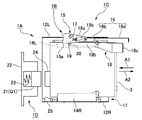
図2は光学ドライブ3およびその支持フレームを示す斜視図であり、図3は支持フレームの斜視図である。図2に示すように、光学ドライブ3は、その上方および側方を覆う支持フレーム11によって保持されている。支持フレーム11は、装置ケース7内におけるレーベルプリンター4の上方に固定されている。この支持フレーム11により、光学ドライブ3の取付位置P1および取付位置P2が規定されている。光学ドライブ3は、支持フレーム11の前方から取付位置P1、P2に挿入される。
(Optical drive attachment / detachment mechanism)
FIG. 2 is a perspective view showing the
パブリッシャー1は、取付位置P1、P2のそれぞれに光学ドライブ3を着脱可能に取り付けるための光学ドライブ着脱機構1A(図5、6、8参照)を備えている。光学ドライブ着脱機構1Aは、上記の支持フレーム11と、光学ドライブ3を取付位置P1、P2から引き抜き不能にするためのロック機構1B(ロック手段:図5、6、8参照)と、ロック機構1Bのロック状態を解除するためのロック解除機構1C(ロック解除手段:図5、6、8参照)を備えている。また、光学ドライブ着脱機構1Aは、光学ドライブ3の後方に配置されたコネクター接続機構1D(図5、6、8〜10参照)を備えている。
The publisher 1 includes an optical drive attaching /
図2、図3に示すように、支持フレーム11は、左右の側板12L、12Rおよび天板13を備えている。側板12L、12Rの下端およびその上方の所定の高さ位置には、上下2段に配置された各光学ドライブ3の左右の側端部分を支持する支持板14L、14Rが2段に配置されている。下側の支持板14L、14Rは、左右の側板12L、12Rの下端を内側に折り曲げて形成されている。また、上側の支持板14L、14Rは、左右の側板12L、12Rに切り込みを入れて内側に折り曲げることにより形成されている。上側の支持板14L、14Rと下側の支持板14L、14Rとの高低差は、上側の光学ドライブ3と下側の光学ドライブ3との間に、排熱用の所定の隙間を確保できるように設定されている。
As shown in FIGS. 2 and 3, the
左側の各支持板14Lの上には、ロックレバー15およびロック解除レバー16が取り付けられている。各支持板14Lの後端寄りの位置から上方に向かって回転支軸17が延びており、各ロックレバー15は、各回転支軸17に回転自在に取り付けられている。また、ロック解除レバー16の後端部分には前後方向に延びる長孔16aが形成され、ここに回転支軸17が挿通されている。これにより、ロック解除レバー16は、側板12Lに沿って前後方向にスライド可能となっている。
On each
図4は、光学ドライブ3を斜め下側から見た斜視図である。光学ドライブ3は、ロックレバー15と対峙する部分に固定されたロック板18を備えている。ロック板18は、光学ドライブ3の筺体の左側面に固定された側板部18aと、光学ドライブ3の筺体底面の左端部分に固定された底板部18bを備えている。底板部18bの後端には、下向きに突出するロックピン19が形成されている。また、底板部18bの前端には、光学ドライブ3の筺体前面よりも更に前方に突出する操作片18cが形成されている。後述するロック解除状態では、操作片18cを前方に引くことにより、光学ドライブ3を支持フレーム11内から前方に引き抜くことができる。
FIG. 4 is a perspective view of the
図5、図6は、光学ドライブ着脱機構1Aを下側から見た状態を示す底面図であり、図5は光学ドライブ3のロック状態、図6は光学ドライブ3が取付位置P1あるいはP2への挿入途中位置にある状態を示している。なお、図5、図6では、支持板14Lを省略し、その輪郭線のみを破線で示している。また、図5、図6における矢印A1は光学ドライブ3の挿入方向であり、矢印A2は光学ドライブ3の引き抜き方向である。
5 and 6 are bottom views showing the optical drive attaching /
図5、図6に示すように、ロックレバー15は、支持フレーム11の後方に向かうに従って幅広となる楔形の平面形状をしており、その後端部分には、光学ドライブ3の側に突出する係合爪15aが形成されている。ロックレバー15の回転支軸17には、ロックレバー15をロック方向に付勢する捻りバネ20が取り付けられている。捻りバネ20による付勢方向(ロック方向)は、図5において矢印Bで示すように、係合爪15aを光学ドライブ3の側に進出させる旋回方向である。
As shown in FIGS. 5 and 6, the
光学ドライブ3が取付位置P1あるいはP2まで挿入されたとき、ロックレバー15は、図5に示すように、捻りバネ20の付勢力により、係合爪15aが支持フレーム11の内側に向けて大きく飛び出した姿勢となっている。この位置が、ロックレバー15のロック位置15Aである。
When the
光学ドライブ3が支持フレーム11内に装着されていないとき、ロックレバー15は、捻りバネ20の付勢力により、図5と同様の姿勢になっている。この状態から、光学ドライブ3を支持フレーム11内に挿入すると、挿入途中で、光学ドライブ3の底面に設けられたロックピン19がロックレバー15に前方から当接し、これを後方に押圧する。このため、ロックレバー15は、捻りバネ20の付勢力に逆らって旋回し、図6に示すように、側板12Lの側に退避する。すなわち、ロックレバー15は、光学ドライブ3の挿入動作に伴ってロック位置15Aから退避し、光学ドライブ3の進入を妨げないように構成されている。
When the
光学ドライブ3が取付位置P1あるいはP2に到達すると、ロックレバー15の後端よりも後方にロックピン19が移動する。このため、ロックレバー15が図5に示すロック位置15Aに戻り、係合爪15aがロックピン19の前方に突出してロックピン19に係合する。よって、光学ドライブ3を引き抜き不能なロック状態が形成される。このように、ロックレバー15、ロックピン19、および捻りバネ20により、光学ドライブ3のロック機構1Bが構成されている。
When the
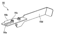
図7はロック解除レバー16を斜め下側から見た斜視図である。ロック解除レバー16の後端部分には、ロックレバー15の上に載ってスライドする水平なスライド片16bが形成されている。スライド片16bの後端には上述した長孔16aが形成されており、長孔16aの前方には、下向きに突出するロック解除ピン16cが形成されている。また、ロック解除レバー16の前端部分には、スライド片16bの前端から前方に延びる解除操作片16dが形成されている。解除操作片16dは、光学ドライブ3が取付位置P1あるいはP2に装着されたとき、その筺体前面よりも前方に突出している。
FIG. 7 is a perspective view of the
図5、図6に示すように、ロックレバー15の前端側にはガイド孔15bが形成されており、ここにロック解除ピン16cが挿入されている。ガイド孔15bは、図5に示すように、ロックレバー15がロック位置15Aにあるとき、光学ドライブ3の挿入方向(矢印A1方向)に対して斜めに延びている。ガイド孔15bの傾き方向は、ロックレバー15の前端側に向かうに従って側板12Lに近づき、後端側に向かうに従って側板12Lから離れる方向となっている。
As shown in FIGS. 5 and 6, a
図8は光学ドライブ着脱機構1Aの底面図であり、ロック解除状態を示している。図5に示す光学ドライブ3のロック状態において、ロック解除レバー16を前方側(矢印A2方向)に引くと、ロック解除ピン16cがガイド孔15b内を前方に移動する。このとき、ガイド孔15bは、ロック解除ピン16cの移動方向に対して上記のように傾斜しているため、ロック解除レバー16の直線運動がロックレバー15の旋回運動に変換され、ロックレバー15が捻りバネ20の付勢力に逆らって旋回し、ロック解除位置15Bに移動する。これにより、ロックレバー15の係合爪15aがロックピン19の前方から退避し、光学ドライブ3を前方に引き抜くことが可能になる。このように、ロック解除レバー16およびこれに形成されたロック解除ピン16c、ならびに、ガイド孔15bにより、ロック解除機構1Cが構成されている。
FIG. 8 is a bottom view of the optical drive attaching /
(コネクター接続機構)
ここで、図5、6、8に示すように、支持フレーム11の後方には、パブリッシャー1内の基板や電源装置からのデータ通信や電源供給用の配線を光学ドライブ3に接続するためのコネクター接続機構1Dが設けられている。図5、6、8では、コネクター接続機構1Dの構成を模式的に示している。また、図9、10はコネクター接続機構1Dおよびその背面側に設けられた背面パネルの斜視図であり、図9は光学ドライブを取り付けた状態、図10は光学ドライブを取り外した状態を示している。
(Connector connection mechanism)
Here, as shown in FIGS. 5, 6, and 8, a connector for connecting data communication and power supply wiring from the substrate in the publisher 1 and the power supply device to the
コネクター接続機構1Dは、支持フレーム11の後方に引き出されている配線ケーブル31、32の端部に設けられている可動コネクター21と、可動コネクター21を前後方向(光学ドライブ3の挿入/引き抜き方向)に移動可能に支持するホルダー22と、可動コネクター21を前方側に付勢する付勢バネ23(付勢手段/弾性部材)を備えている。ホルダー22は、支持フレーム11の後方に固定状態で設置されている。ホルダー22内には、付勢バネ23が前後方向に伸縮可能な状態で配置され、その前端が可動コネクター21の後端に連結されている。配線ケーブル31、32の他方の端部には、パブリッシャー1内の基板や電源装置への接続用のコネクター31a、32aが設けられている。
The
光学ドライブ3の後端面には、可動コネクター21に対して着脱可能な固定コネクター24が設けられている。固定コネクター24は、光学ドライブ3が支持フレーム11に挿入されるとき、その後方に設置されている可動コネクター21と正対する。可動コネクター21は、光学ドライブ3を支持フレーム11内から取り外しているときには、付勢バネ23の弾性復帰力により、図6、図10に示す突出位置Q1まで飛び出している。可動コネクター21の前後方向の可動範囲はホルダー22によって規制されており、その前端位置が突出位置Q1となるように構成されている。
A fixed
光学ドライブ3を支持フレーム11内に挿入すると、取付位置P1、P2の手前の所定位置で固定コネクター24が可動コネクター21に突き当たる。その後は、付勢バネ23の付勢力に逆らって光学ドライブ3を押し込むため、両コネクターが嵌合方向に押し付けられる。光学ドライブ3が取付位置P1、P2まで挿入されたとき、可動コネクター21は、図5、図8に示すように、突出位置Q1よりも後方の接続位置Q2まで押し込まれている。可動コネクター21の可動範囲の後端位置は、接続位置Q2よりもわずかに後方に設定されているため、光学ドライブ3を取り付けるときは、一旦取付位置P1、P2よりも奥まで光学ドライブ3を押し込む。これにより、可動コネクター21をその可動範囲の後端位置に位置決めした状態で固定コネクター24を押し付けることができ、両コネクターを確実に嵌合させることができる。
When the
固定コネクター24と可動コネクター21を嵌合させた後、光学ドライブ3から手を離すと、付勢バネ23の弾性復帰力によって光学ドライブ3が前方に戻り、上述したように、ロックピン19がロックレバー15に後方から押し付けられた状態となるように位置決めされる。すなわち、光学ドライブ3は、取付位置P1、P2に位置決めされたとき、両コネクターを介して、付勢バネ23の弾性復帰力により、後方から前方に向けて付勢されている。
After the fixed
上述したロック解除レバー16の操作によって図8に示すロック解除状態になると、光学ドライブ3は、自動的に前方(矢印A2方向)に押し出される。本実施形態では、ホルダー22によって可動コネクター21の可動範囲が規制されており、光学ドライブ3がロック解除状態になったときには、可動コネクター21が固定コネクター24に接続された状態のままで突出位置Q1まで押し出されて停止する。すなわち、ロック解除時の光学ドライブ3の押し出し寸法は、接続位置Q2から突出位置Q1までの可動コネクター21の移動距離に一致している。すなわち、可動コネクター21の可動範囲および付勢バネ23の弾性復帰力を適宜設定することにより、ロック解除時の光学ドライブ3の押し出し寸法を、予め設定した所望の寸法にすることができる。
When the
図9、10に示すように、ホルダー22は、パブリッシャー1における装置ケース7の背面パネル7aの前面側に固定されている。本実施形態では、2台の光学ドライブ3の取付位置P1、P2に対応して、上下2箇所にコネクター接続機構1Dが設けられている。上側のコネクター接続機構1Dのホルダー22は、背面パネル7aに固定された排熱用のフード33の上部に固定されている。フード33の後方には排熱用のファン(図示省略)が取り付けられている。フード33は、前方に向かって張り出した形状をしており、その前端中央には横長のスリット状の排気口33aが形成されている。排気口33aは、上側の取付位置P1と下側の取付位置P2に取り付けられた2台の光学ドライブ3の隙間に対峙しているため、この隙間に効率的に外気を導入することができる。
As shown in FIGS. 9 and 10, the
支持フレーム11における右側の側板12Rの後端には、左側に向けて突出する突出部25が設けられている。突出部25は、固定コネクター24を可動コネクター21に正対させて光学ドライブ3を挿入したとき、図5、図8に示すように、光学ドライブ3の筐体右側面に、突出部25の先端が右側から当接するように構成されている。
A
光学ドライブ3には、その左端部分にのみロック機構1Bが設けられ、右端部分にはロック機構1Bが設けられていない。一方、上述したコネクター接続機構1Dからの付勢力は、固定コネクター24が設けられた光学ドライブ3の後端面の右端寄りの位置に作用している。このような配置では、コネクター接続機構1Dの付勢力により、光学ドライブ3を左方向(図5の矢印C方向)に旋回させる回転力が生じる。しかしながら、本実施形態では、光学ドライブ3の後端部分に右側から当接する突出部25が設けられているため、光学ドライブ3の左方向への旋回が規制され、光学ドライブ3を正面を向いた姿勢に保持することができる。
The
以上のように、本実施形態では、光学ドライブ3の挿入時に、付勢バネ23によって可動コネクター21を固定コネクター24に押し付けて嵌合させることができる。従って、光学ドライブ3の取付時におけるコネクター接続作業が容易である。また、可動コネクター21がホルダー22によって規定される可動範囲内で進退可能であるため、可動コネクター21をその可動範囲内で移動させることができる。従って、光学ドライブ3の位置決めに伴う固定コネクター24および可動コネクター21の接続性の低下を抑制することができ、光学ドライブ3の取付位置精度とコネクター接続性の両立を図ることができる。
As described above, in this embodiment, when the
また、本実施形態では、光学ドライブ3が取付位置P1、P2に装着されたとき、付勢バネ23の弾性復帰力により、可動コネクター21および固定コネクター24を介して、光学ドライブ3がその引き抜き方向に付勢されている。従って、ロック状態において光学ドライブ3が可能な限り前方に押し出され、ロックピン19がロックレバー15に押し当てられる位置で光学ドライブ3が位置決めされる。従って、取付位置P1、P2における光学ドライブ3の位置決めが確実になされる。これにより、光学ドライブ3とオートローダー2との間で光ディスク10を確実に受け渡すことができ、光ディスク10の搬送信頼性が向上する。
In the present embodiment, when the
また、光学ドライブ3を取付位置P1、P2まできちんと挿入できていない場合にはロック状態が形成されず、このときには、付勢バネ23の付勢力により、光学ドライブ3が支持フレーム11から前方に押し出される。従って、取付位置P1、P2への取付が完了したか否かを一目で確認できる。更に、ロック解除機構1Cによるロック解除を行ったときにも、光学ドライブ3が自動的に支持フレーム11内から前方に押し出される。よって、光学ドライブ3を容易に引き抜くことができる。また、可動コネクター21の可動範囲が規制されているため、光学ドライブ3の引き抜き動作に伴って自動的に可動コネクター21から固定コネクター24が引き抜かれる。よって、光学ドライブ3の取り外し作業が容易である。
Further, when the
(他の実施形態)
上記実施形態は、多数の光ディスク10へのデータの書き込みを連続で行うためのパブリッシャー1に本発明を適用したものであったが、本発明は、光学ドライブを着脱可能に装着し、光ディスクの搬送機構を備える各種の光ディスク処理装置に適用できる。
(Other embodiments)
In the above embodiment, the present invention is applied to the publisher 1 for continuously writing data on a large number of
1…パブリッシャー(光ディスク処理装置)、1A…光学ドライブ着脱機構、1B…ロック機構、1C…ロック解除機構、1D…コネクター接続機構、2…オートローダー(搬送機構)、2a…垂直ガイド軸、2b…ディスクキャリア、3…光学ドライブ、3a…ディスクトレイ、4…レーベルプリンター、4a…ディスクトレイ、4b…カートリッジ装着部、5…供給スタッカー、6…収納スタッカー、7…装置ケース、7a…背面パネル、8…開閉扉、9…開閉扉、10…光ディスク、10A…ブランクディスク、10B…完成ディスク、11…支持フレーム、12L…側板、12R…側板、13…天板、14L…支持板、14R…支持板、15…ロックレバー、15a…係合爪、15b…ガイド孔、15A…ロック位置、15B…ロック解除位置、16…ロック解除レバー、16a…長孔、16b…スライド片、16c…ロック解除ピン、16d…解除操作片、17…回転支軸、18…ロック板、18a…側板部、18b…底板部、18c…操作片、19…ロックピン、20…捻りバネ(第2付勢手段)、21…可動コネクター、22…ホルダー、23…付勢バネ(付勢手段/弾性部材)、24…固定コネクター、25…突出部、31…配線ケーブル、31a…コネクター、32…配線ケーブル、32a…コネクター、33…フード、33a…排気口、P1…取付位置、P2…取付位置、Q1…突出位置、Q2…接続位置
DESCRIPTION OF SYMBOLS 1 ... Publisher (optical disk processing apparatus), 1A ... Optical drive attachment / detachment mechanism, 1B ... Lock mechanism, 1C ... Lock release mechanism, 1D ... Connector connection mechanism, 2 ... Autoloader (conveyance mechanism), 2a ... Vertical guide shaft, 2b ... Disc carrier, 3 ... optical drive, 3a ... disc tray, 4 ... label printer, 4a ... disc tray, 4b ... cartridge mounting part, 5 ... supply stacker, 6 ... storage stacker, 7 ... device case, 7a ... back panel, 8 Open / close door, 9 ... Open / close door, 10 ... Optical disc, 10A ... Blank disc, 10B ... Complete disc, 11 ... Support frame, 12L ... Side plate, 12R ... Side plate, 13 ... Top plate, 14L ... Support plate, 14R ... Support plate , 15: Lock lever, 15a: Engaging claw, 15b: Guide hole, 15A: Lock position, 15B: Lock Release position, 16 ... Lock release lever, 16a ... Long hole, 16b ... Slide piece, 16c ... Lock release pin, 16d ... Release operation piece, 17 ... Rotating spindle, 18 ... Lock plate, 18a ... Side plate, 18b ... Bottom plate , 18c ... operation piece, 19 ... lock pin, 20 ... torsion spring (second biasing means), 21 ... movable connector, 22 ... holder, 23 ... biasing spring (biasing means / elastic member), 24 ... fixed Connector, 25 ... Projection, 31 ... Wiring cable, 31a ... Connector, 32 ... Wiring cable, 32a ... Connector, 33 ... Hood, 33a ... Exhaust port, P1 ... Installation position, P2 ... Installation position, Q1 ... Projection position, Q2 ... connection position
Claims (5)
当該固定コネクターに対して着脱可能に構成された可動コネクターと、
当該可動コネクターを、前記固定コネクターに正対する姿勢で、且つ、予め設定した取付位置への前記光学ドライブの移動方向に進退可能に保持するホルダーと、
前記可動コネクターを前記光学ドライブの側に付勢する付勢手段とを備えることを特徴とする光学ドライブのコネクター接続機構。 A fixed connector provided in the optical drive;
A movable connector configured to be detachable from the fixed connector;
A holder for holding the movable connector in a posture facing the fixed connector and capable of moving back and forth in a moving direction of the optical drive to a predetermined mounting position;
A connector connecting mechanism for an optical drive, comprising: an urging means for urging the movable connector toward the optical drive.
前記ホルダーは、前記可動コネクターの可動範囲を規制していることを特徴とする光学ドライブのコネクター接続機構。 In claim 1,
The connector connecting mechanism for an optical drive, wherein the holder restricts a movable range of the movable connector.
前記付勢手段は、前記可動コネクターの進退方向に伸縮可能な弾性部材であり、
当該弾性部材は、その弾性復帰力により、前記可動コネクターおよび前記固定コネクターを介して、前記光学ドライブを、前記取付位置から予め設定した寸法だけ押し出し可能に構成されていることを特徴とする光学ドライブのコネクター接続機構。 In claim 1 or 2,
The biasing means is an elastic member that can expand and contract in the advancing and retracting direction of the movable connector,
The elastic drive is configured to be able to push out the optical drive by a predetermined dimension from the mounting position via the movable connector and the fixed connector by the elastic return force. Connector connection mechanism.
前記取付位置において前記光学ドライブを支持する支持フレームと、
前記光学ドライブを前記取付位置まで挿入したとき、当該光学ドライブを前記取付位置から引き抜き不能なロック状態を形成するためのロック手段と、
当該ロック手段のロック状態を解除するためのロック解除手段を有することを特徴とする光学ドライブ着脱機構。 The connector connection mechanism according to any one of claims 1 to 3,
A support frame that supports the optical drive at the mounting position;
Lock means for forming a locked state in which the optical drive cannot be pulled out from the mounting position when the optical drive is inserted to the mounting position;
An optical drive attaching / detaching mechanism comprising a lock releasing means for releasing the lock state of the lock means.
当該光学ドライブ着脱機構によって着脱可能に取り付けられる光学ドライブと、
前記取付位置に装着された前記光学ドライブに光ディスクを搬送するための搬送機構とを有することを特徴とする光ディスク処理装置。
An optical drive attaching / detaching mechanism according to claim 4,
An optical drive detachably attached by the optical drive attaching / detaching mechanism;
An optical disk processing apparatus comprising: a transport mechanism for transporting an optical disk to the optical drive mounted at the mounting position.
Priority Applications (1)
| Application Number | Priority Date | Filing Date | Title |
|---|---|---|---|
| JP2011140626A JP2013008418A (en) | 2011-06-24 | 2011-06-24 | Connector connection mechanism of optical drive, optical drive attachment/detachment mechanism, and optical disk processor |
Applications Claiming Priority (1)
| Application Number | Priority Date | Filing Date | Title |
|---|---|---|---|
| JP2011140626A JP2013008418A (en) | 2011-06-24 | 2011-06-24 | Connector connection mechanism of optical drive, optical drive attachment/detachment mechanism, and optical disk processor |
Publications (2)
| Publication Number | Publication Date |
|---|---|
| JP2013008418A true JP2013008418A (en) | 2013-01-10 |
| JP2013008418A5 JP2013008418A5 (en) | 2014-06-19 |
Family
ID=47675643
Family Applications (1)
| Application Number | Title | Priority Date | Filing Date |
|---|---|---|---|
| JP2011140626A Withdrawn JP2013008418A (en) | 2011-06-24 | 2011-06-24 | Connector connection mechanism of optical drive, optical drive attachment/detachment mechanism, and optical disk processor |
Country Status (1)
| Country | Link |
|---|---|
| JP (1) | JP2013008418A (en) |
Cited By (3)
| Publication number | Priority date | Publication date | Assignee | Title |
|---|---|---|---|---|
| JP2016051490A (en) * | 2014-08-29 | 2016-04-11 | シャープ株式会社 | Hdd tray mounting structure and information processing terminal device |
| JP2020191366A (en) * | 2019-05-21 | 2020-11-26 | ファナック株式会社 | Structure for attaching/detaching fan unit to/from body of electric equipment, connector connecting body of electric equipment and fan unit, and electric equipment |
| US11797064B2 (en) | 2020-05-22 | 2023-10-24 | Shanghai Moruan Telecom Technology Co., Ltd. | Hard disk fixing device and main unit |
-
2011
- 2011-06-24 JP JP2011140626A patent/JP2013008418A/en not_active Withdrawn
Cited By (6)
| Publication number | Priority date | Publication date | Assignee | Title |
|---|---|---|---|---|
| JP2016051490A (en) * | 2014-08-29 | 2016-04-11 | シャープ株式会社 | Hdd tray mounting structure and information processing terminal device |
| JP2020191366A (en) * | 2019-05-21 | 2020-11-26 | ファナック株式会社 | Structure for attaching/detaching fan unit to/from body of electric equipment, connector connecting body of electric equipment and fan unit, and electric equipment |
| JP7264719B2 (en) | 2019-05-21 | 2023-04-25 | ファナック株式会社 | Detachable structure for fan unit to main body of electrical equipment, connector for connecting main body of electrical equipment and fan unit, and electrical equipment |
| US11920612B2 (en) | 2019-05-21 | 2024-03-05 | Fanuc Corporation | Attachment structure for attaching fan unit to main body of electrical equipment, connector connecting main body of electrical equipment and fan unit, and electrical equipment |
| US11797064B2 (en) | 2020-05-22 | 2023-10-24 | Shanghai Moruan Telecom Technology Co., Ltd. | Hard disk fixing device and main unit |
| JP7397218B2 (en) | 2020-05-22 | 2023-12-12 | 上海摩軟通訊技術有限公司 | Hard disk fixing device and host computer |
Similar Documents
| Publication | Publication Date | Title |
|---|---|---|
| JP5577678B2 (en) | Cartridge drive device | |
| JPH0348765Y2 (en) | ||
| JP2011108315A (en) | Disk loading mechanism | |
| JP2013008416A (en) | Optical disk processor and optical drive attachment/detachment mechanism thereof | |
| JP2013008418A (en) | Connector connection mechanism of optical drive, optical drive attachment/detachment mechanism, and optical disk processor | |
| JP2008226364A (en) | Carrying mechanism, carrying device and electronic equipment | |
| JP2012074102A (en) | Library device | |
| CN108885883B (en) | Magnetic disk transfer device | |
| US6512653B1 (en) | Cassette changer | |
| JP5842530B2 (en) | Connector connection mechanism of optical drive, optical drive attaching / detaching mechanism, and optical disk processing apparatus | |
| KR20130027423A (en) | Disk conveying device | |
| JP6152687B2 (en) | Disk transport device | |
| JP2014026691A (en) | Magazine chuck | |
| JP3855239B2 (en) | Disk device with tray drop prevention mechanism | |
| JP2008127192A (en) | Paper feeding part and recorder having the same | |
| JP4285327B2 (en) | Disk unit | |
| WO2019069480A1 (en) | Disc device | |
| JP5938694B2 (en) | Insertion / removal device | |
| US20100050192A1 (en) | Disk conveyance device and disk device | |
| JP5445055B2 (en) | Disc cartridge | |
| JP3900878B2 (en) | Disk unit | |
| JP5051207B2 (en) | Disc cartridge | |
| JP5978914B2 (en) | Media drive and media processing apparatus having the same | |
| JP3807277B2 (en) | Disk unit | |
| JP3807280B2 (en) | Disk unit |
Legal Events
| Date | Code | Title | Description |
|---|---|---|---|
| A521 | Written amendment |
Free format text: JAPANESE INTERMEDIATE CODE: A523 Effective date: 20140428 |
|
| A621 | Written request for application examination |
Free format text: JAPANESE INTERMEDIATE CODE: A621 Effective date: 20140428 |
|
| RD04 | Notification of resignation of power of attorney |
Free format text: JAPANESE INTERMEDIATE CODE: A7424 Effective date: 20150107 |
|
| A977 | Report on retrieval |
Free format text: JAPANESE INTERMEDIATE CODE: A971007 Effective date: 20150713 |
|
| A131 | Notification of reasons for refusal |
Free format text: JAPANESE INTERMEDIATE CODE: A131 Effective date: 20150901 |
|
| A761 | Written withdrawal of application |
Free format text: JAPANESE INTERMEDIATE CODE: A761 Effective date: 20151030 |