JP2012532066A - Protective tarpaulin system for motor vehicle - Google Patents
Protective tarpaulin system for motor vehicle Download PDFInfo
- Publication number
- JP2012532066A JP2012532066A JP2012519038A JP2012519038A JP2012532066A JP 2012532066 A JP2012532066 A JP 2012532066A JP 2012519038 A JP2012519038 A JP 2012519038A JP 2012519038 A JP2012519038 A JP 2012519038A JP 2012532066 A JP2012532066 A JP 2012532066A
- Authority
- JP
- Japan
- Prior art keywords
- waterproof sheet
- motor vehicle
- protective
- drum
- hose
- Prior art date
- Legal status (The legal status is an assumption and is not a legal conclusion. Google has not performed a legal analysis and makes no representation as to the accuracy of the status listed.)
- Pending
Links
Images


Classifications
-
- B—PERFORMING OPERATIONS; TRANSPORTING
- B60—VEHICLES IN GENERAL
- B60J—WINDOWS, WINDSCREENS, NON-FIXED ROOFS, DOORS, OR SIMILAR DEVICES FOR VEHICLES; REMOVABLE EXTERNAL PROTECTIVE COVERINGS SPECIALLY ADAPTED FOR VEHICLES
- B60J11/00—Removable external protective coverings specially adapted for vehicles or parts of vehicles, e.g. parking covers
- B60J11/02—Covers wound on rollers
Abstract
一例として乗用車を含むモータービークル(V)に用いられる保護防水シートシステム(1)であって、少なくとも部分的にはモータービークル(V)を覆って保護する柔軟な防水シート(6)を有し、防水シート(6)にはモータービークル上を長さ方向に進む方向である縦方向(L)が定められており、防水シート(6)は前記縦方向(L)に延びる1以上の補強部材(61; 61´)を備え、当該補強部材(61; 61´)は柔軟な防水シートに縦方向の剛性をある程度もたらすことで、モータービークルを防水シートで覆う作業を容易にすること、を特徴とする保護防水シートシステム。
【選択図】図3As an example, a protective tarpaulin system (1) used for a motor vehicle (V) including a passenger car, which has a flexible tarpaulin (6) that at least partially covers and protects the motor vehicle (V), The waterproof sheet (6) has a longitudinal direction (L) that is a longitudinal direction on the motor vehicle, and the waterproof sheet (6) has one or more reinforcing members (in the longitudinal direction (L)). 61; 61 ′), and the reinforcing member (61; 61 ′) is characterized by facilitating the work of covering the motor vehicle with the waterproof sheet by providing a certain degree of longitudinal rigidity to the flexible waterproof sheet. Protective tarpaulin system.
[Selection] Figure 3
Description
本発明は、後部バンパ、トランク、ルーフ、フードそして前部バンパを有する乗用車などのモータービークル(自動車)に用いられる保護防水シートシステムに関する。 The present invention relates to a protective tarpaulin system used in a motor vehicle (automobile) such as a passenger car having a rear bumper, a trunk, a roof, a hood, and a front bumper.
こうした柔軟な防水シートは、少なくとも部分的にモータービークルを覆うためのものであり、後部バンパから前部バンパまで広がる形で用いられてモータービークルを保護する。防水シートは、モータービークルの後部から前部までの長手方向が縦方向と規定される。言い換えると、防水シートを縦方向に広げる、または引っ張ることで、モータービークルは後部から前部に向かって(または、その反対方向に)覆われる。従って、本発明の効果的な適用分野は、自家用車の分野となるが、本発明は更に、他の種類のモータービークル(例えば、商用車、トラック、トレーラ、ボートその他)に使用することもできる。 Such a flexible tarpaulin is intended to at least partially cover the motor vehicle and is used in such a manner as to extend from the rear bumper to the front bumper to protect the motor vehicle. In the waterproof sheet, the longitudinal direction from the rear part to the front part of the motor vehicle is defined as the vertical direction. In other words, the motor vehicle is covered from the rear to the front (or in the opposite direction) by spreading or pulling the waterproof sheet in the vertical direction. Thus, although the effective field of application of the present invention is in the field of private vehicles, the present invention can also be used in other types of motor vehicles (eg, commercial vehicles, trucks, trailers, boats, etc.). .
モータービークル用の保護防水シートは古くから存在している。最も単純な型は、単なる柔軟な防水シートであって、これを展開して引っ張り、少なくとも部分的にモータービークルの上部を上から覆う、というものである。こうして所定位置に配置された後、防水シートは各種技術(例えば、ゴムバンド、フックなど)を用いてモータービークルに固定される場合もある。こうした初歩的な種類の保護防水シートには2つの問題がある。第1の問題はモータービークルを覆う作業に関するものであり、こうした作業の中心は、防水シートをモータービークルの上部にかぶせて広げる作業となる。防水シートをモータービークル上に正しく配置するには、何回かモータービークルの周囲を回らなければならない。第2の問題は、不使用時、モータービークルから外された状態の防水シートの保管に関連するものである。防水シートを正しく畳んで、可能な限り嵩張らないようにする必要がある。保管に関する問題は、より複雑な保護防水シートシステムを用いれば、部分的には解決される。それは、巻き取りドラムを用いて保護防水シートを巻き取り、保管できる状態にするものである。そして、防水シートを使用したい時には、防水シートの自由端を引っ張って、巻き取りドラムから引き出す。こうした巻き取りドラムは、モータービークルの前部または後部、あるいはルーフ上に設置される。また、モータービークルの後部のトランクまたは荷物入れの内部に巻き取りドラムを組み込むことも可能である。しかし、巻き取りドラムを用いる防水シートシステムであっても、モータービークルを防水シートで覆う作業に関連する問題は解決できない。モータービークルの上部に適正な状態でかぶさるように柔軟な防水シートを広げるためには、やはり防水シートの自由端を引っぱって動き回る必要がある。言い換えると、巻き取りドラムは、防水シートを巻き取る作業、あるいはモータービークルから外す作業においては有用かつ有効であるが、防水シートを引き出す作業、あるいはモータービークルを覆う作業においては、全く役に立たない。 Protective tarpaulins for motor vehicles have existed for a long time. The simplest mold is simply a flexible tarpaulin that unfolds and pulls and at least partially covers the top of the motor vehicle from above. After being arranged in this way, the waterproof sheet may be fixed to the motor vehicle using various techniques (for example, rubber bands, hooks, etc.). There are two problems with these basic types of protective waterproof sheets. The first problem relates to the work of covering the motor vehicle, and the center of such work is the work of spreading the waterproof sheet over the top of the motor vehicle. In order to properly place the tarpaulin on the motor vehicle, it has to go around the motor vehicle several times. The second problem is related to the storage of the waterproof sheet that is removed from the motor vehicle when not in use. It is necessary to fold the tarpaulin correctly so that it is not as bulky as possible. Storage problems are partially solved by using more complex protective tarpaulin systems. That is, the protective waterproof sheet is wound up using a winding drum so that it can be stored. When it is desired to use the waterproof sheet, the free end of the waterproof sheet is pulled out and pulled out from the winding drum. Such a winding drum is installed on the front or rear of the motor vehicle or on the roof. It is also possible to incorporate a take-up drum inside the trunk or luggage compartment at the rear of the motor vehicle. However, even a waterproof sheet system using a winding drum cannot solve the problems related to the work of covering the motor vehicle with the waterproof sheet. In order to spread a flexible tarpaulin so as to cover the top of the motor vehicle in an appropriate state, it is also necessary to move around by pulling the free end of the tarpaulin. In other words, the take-up drum is useful and effective in the work of winding up the waterproof sheet or removing it from the motor vehicle, but is completely useless in the work of drawing out the waterproof sheet or covering the motor vehicle.
本発明の目的は、モータービークルを防水シートで覆う作業をより簡単にすることであり、それによって、防水シートを所定位置に設置する作業に必要なユーザの関与を、あとえあったとしても、小さくすることである。本発明は、巻き取りドラムを用いる防水シートシステムに適用するのが好ましいが、そうした1つの実施の形態には限定されない。本発明のもう1つの目的は、防水シートの取り外し作業を妨げたり、複雑化させたりすることなしに、モータービークルを防水シートで覆う作業をより簡単にし、そして自動化することである。本発明は更に、複雑な機構によって取り除いたり、畳んだり、格納したりする必要のある堅固な構造物を防水シートに設けることなく、防水シートをかぶせる作業をより簡単にすることを目的とする。 The purpose of the present invention is to make it easier to cover the motor vehicle with the waterproof sheet, and thereby the user's involvement necessary for the work of installing the waterproof sheet in a predetermined position, To make it smaller. The present invention is preferably applied to a waterproof sheet system using a winding drum, but is not limited to such one embodiment. Another object of the present invention is to simplify and automate the task of covering the motor vehicle with the tarpaulin without obstructing or complicating the tarpaulin removal operation. Another object of the present invention is to make it easier to cover the waterproof sheet without providing the waterproof sheet with a rigid structure that needs to be removed, folded, or stored by a complicated mechanism.
そこで、本発明が提供するのは、一例として乗用車を含むモータービークルに用いられる保護防水シートシステムであって、少なくとも部分的にはモータービークルを覆って保護する柔軟な防水シートを有し、防水シートにはモータービークル上を長さ方向に進む方向である縦方向が定められており、防水シートは前記縦方向に延びる1以上の補強部材を備え、当該補強部材は柔軟な防水シートに縦方向の剛性をもたらすことで、モータービークルを防水シートで覆う作業を容易にし、効果的な構成としてモータービークルの後部バンパに設置された巻き取りドラムを更に有し、防水シートは巻き取りドラムに巻き取り可能であって、巻き取りドラムによって巻き取り状態または引き出し状態とされ、前記1以上の補強部材は、巻き取りドラムに対して垂直な方向に延びており、巻き取りドラムまたは当該巻き取りドラムとは別個の巻き取りシャフトに巻き取りが可能であって、巻き取りドラムをそれ自体の軸を中心に回転させるモータを更に有すること、を特徴とする保護防水シートシステムである。 Accordingly, the present invention provides, as an example, a protective waterproof sheet system used for a motor vehicle including a passenger car, and has a flexible waterproof sheet that covers and protects the motor vehicle at least partially. Defines a longitudinal direction that is a longitudinal direction on the motor vehicle, and the waterproof sheet includes one or more reinforcing members extending in the longitudinal direction, and the reinforcing member is disposed on the flexible waterproof sheet in the longitudinal direction. By providing rigidity, it is easy to cover the motor vehicle with the waterproof sheet, and as an effective configuration, it further has a winding drum installed on the rear bumper of the motor vehicle, and the waterproof sheet can be wound on the winding drum And the one or more reinforcing members are wound up by a winding drum. A motor that can be wound around a winding drum or a winding shaft that is separate from the winding drum, and that rotates the winding drum about its own axis. Furthermore, it is a protection waterproof sheet system characterized by having.
また、巻き取りまたは引き出し中の前記1以上の補強部材を縦方向にガイドするガイド手段を更に有する、とするのが効果的である。
また、ガイド手段は2つの回転押圧ローラから成り、巻き取りまたは引き出し中の補強部材は、当該2つの回転押圧ローラの間を通る、とするのが好ましい。
また、前記1以上の補強部材は起動手段を備えており、当該起動手段は前記補強部材に作用して、当該補強部材の状態を補強部材が剛性を有する起動状態と補強部材が柔らかい休止状態との間で選択的に切り替える、とするのが効果的である。これは本発明の非常に効果的な特性であり、その本質は、状態を制御することのできる1以上の補強部材の使用にある。当該補強部材の状態は、モータービークルを防水シートで覆う作業の間だけ一時的に剛性を備え、それ以外の時間は可撓性または柔軟であって、防水シートの柔軟特性の全てが回復される、という形で制御される。効果的な実施の形態における防水シートは、2つ以上の補強部材を有し、効果的な構成として、これら補強部材は連結部材によって相互接続されている。連結部材は堅いものとすることもできるが、必須ではない。ただし、設ける補強部材の数を3つ以上として、その一部は、縦方向ではなく、横方向または前記縦方向に直交する方向に延びる構成とすることもできる。補強部材の形状は、実質的に真っ直ぐとしてもよいし、逆に、カーブした形としてもよい。
In addition, it is effective to further include guide means for guiding the one or more reinforcing members during winding or drawing in the vertical direction.
Moreover, it is preferable that a guide means consists of two rotation press rollers, and the reinforcement member in winding or drawing | extracting passes between the two rotation press rollers.
Further, the one or more reinforcing members are provided with an activating means, and the activating means acts on the reinforcing member to change the state of the reinforcing member into an activated state in which the reinforcing member has rigidity and an inactive state in which the reinforcing member is soft. It is effective to selectively switch between. This is a very effective property of the present invention, the essence of which is the use of one or more reinforcing members that can control the condition. The state of the reinforcing member is temporarily rigid only during the operation of covering the motor vehicle with the waterproof sheet, and is flexible or soft at other times, so that all the flexible characteristics of the waterproof sheet are restored. It is controlled in the form of. The waterproof sheet in the effective embodiment has two or more reinforcing members, and as an effective configuration, these reinforcing members are interconnected by connecting members. The connecting member can be rigid, but is not essential. However, the number of reinforcing members to be provided may be three or more, and a part thereof may be configured to extend in the horizontal direction or the direction perpendicular to the vertical direction instead of the vertical direction. The shape of the reinforcing member may be substantially straight, or conversely, may be a curved shape.
また、特に効果的な局面として、前記1以上の補強部材は、圧力の加わった流体で膨張させられる膨張式ホースから成ること、とする。
また、起動手段は、ポンプまたはコンプレッサである空気注入手段から成り、前記1以上の補強部材とは流体による連通状態である、とするのが効果的である。
また、防水シートは、モータービークルの前部を覆う自由端と、巻き取りドラムに固定される接続端とを有し、前記1以上の補強部材は自由端と接続端との間に延びており、空気注入手段は供給管を介して前記1以上の補強部材に接続されており、供給管は自由端の近傍で前記補強部材に接続されており、それによって、前記補強部材は自由端から接続端にむかって膨張していく、とするのが好ましい。好ましい構成として、前記1以上の補強部材および/または供給管は、前記縦方向に対してわずかに傾斜した形で延びており、それによって、巻き取り格納状態における厚みが大きくなるのを回避している。
As a particularly effective aspect, the one or more reinforcing members are made of an inflatable hose that is inflated with a fluid under pressure.
In addition, it is effective that the starting means comprises air injecting means that is a pump or a compressor, and the one or more reinforcing members are in a fluid communication state.
The waterproof sheet has a free end covering the front of the motor vehicle and a connection end fixed to the take-up drum, and the one or more reinforcing members extend between the free end and the connection end. The air injection means is connected to the one or more reinforcing members via a supply pipe, and the supply pipe is connected to the reinforcing member in the vicinity of the free end, whereby the reinforcing member is connected from the free end. It is preferable to expand toward the end. As a preferred configuration, the one or more reinforcing members and / or supply pipes extend in a slightly inclined form with respect to the longitudinal direction, thereby avoiding an increase in thickness in the retracted storage state. Yes.
また、変形例として、ガイド手段は2つの回転押圧ローラから成り、当該回転押圧ローラは、引き出し中の膨張式ホースを局所的に挟み付けて空気が通らない状態とすることで、膨張式ホースのうち巻き取りドラムに巻かれた状態にある部分が膨張することを防ぐこと、とする。
また、防水シートと、補強部材と、供給管とは別々に巻き取りドラムに巻き付けることが可能であり、それによって、巻き取り状態における厚みが過剰に大きくなるのを防止すること、とするのが効果的である。
Further, as a modification, the guide means is composed of two rotary pressing rollers, and the rotary pressing roller locally sandwiches the inflatable hose that is being pulled out so that air does not pass therethrough. Of these, the portion wound on the winding drum is prevented from expanding.
Further, the waterproof sheet, the reinforcing member, and the supply pipe can be separately wound around the winding drum, thereby preventing the thickness in the winding state from becoming excessively large. It is effective.
このように、本発明は、圧力の加わった流体(通常は空気)で膨張する1以上の膨張式のホースまたは管を使用するものとして考えられている。ただし、他の気体または液体の使用も可能であろう。膨張していない状態でのホースは、全く柔軟であり、好ましくは平らであり、そのため、ホースのために防水シートの柔軟性が損なわれたり、厚みが大きくなったりすることはない。従って、ホースが萎んだ状態の防水シートは、非常に容易に巻き取りドラムに巻き取ることができる。反対に、膨張した状態のホースは、内部に圧力の加わった流体が入ることで、剛性を得るか、または堅くなる。こうして堅さまたは剛性が加わった防水シートは、実質的に堅いプレートのように、モータービークルにかぶせて広げることができる。当然のことながら、ホースは縦方向に延ばすことが好ましい。防水シートは前述した方向に引き出されるからである。しかしながら、ホースがそれ自体の上に重なる形で巻かれるのを避けるために、巻き取りドラムに対してわずかに傾斜した状態でホースを延ばすことが好ましい。そうすれば、ホースはドラムに螺旋状に巻かれて行くことになる。同じことは、ポンプまたはコンプレッサをホースに接続する、小さな供給管にも当てはまる。加えて、防水シートの先頭側端部からホースを膨らませて行くように構成することで、ホースのうち巻き取りドラムに巻かれた状態の部分まで膨らんでしまう事態を回避することができる。これによって、ホースの膨張の結果としてシート収容容器内部に防水シートが詰まってしまう危険は排除される。言い換えれば、ホースのうちドラムからすでに引き出された部分だけが、圧力の加わった流体で膨張させられ、巻かれたままの部分は平らな状態を保つ。 Thus, the present invention is contemplated as using one or more inflatable hoses or tubes that expand with a fluid under pressure (usually air). However, other gases or liquids could be used. The hose in the unexpanded state is quite flexible, preferably flat, so that the flexibility of the tarpaulin is not impaired or increased in thickness due to the hose. Therefore, the waterproof sheet with the hose deflated can be wound up on the winding drum very easily. On the other hand, the hose in the inflated state gains rigidity or becomes stiff when the fluid under pressure enters inside. The tarpaulin with added rigidity or rigidity can be spread over the motor vehicle like a substantially rigid plate. Of course, the hose is preferably extended in the longitudinal direction. This is because the waterproof sheet is pulled out in the above-described direction. However, it is preferable to extend the hose with a slight inclination with respect to the take-up drum in order to avoid the hose being wound on top of itself. Then, the hose will be spirally wound around the drum. The same is true for small supply pipes that connect pumps or compressors to hoses. In addition, by configuring the hose to inflate from the leading end of the waterproof sheet, it is possible to avoid a situation in which the hose is inflated to the portion wound around the take-up drum. This eliminates the risk of the waterproof sheet becoming clogged inside the sheet container as a result of the expansion of the hose. In other words, only the part of the hose that has already been withdrawn from the drum is inflated with the fluid under pressure, while the wound part remains flat.
また、別の第2の実施の形態では、前記1以上の補強部材は、引き出された状態では真っ直ぐで硬い巻き取り可能な帯材から成ること、とする。一例として、形状加工した金属帯材(巻尺用帯材など)を使用することが可能である。また、帯材は、巻き取りドラムに平行に延びた専用の巻き取りシャフトに巻き付けられ、当該帯材は巻き取りドラムによって引き出し状態とされる、とするのが効果的である。一例として、刻みをつけた帯材を、ラックのように、それ自体に刻みをつけたドラムで巻く、という構成が可能である。 In another second embodiment, the one or more reinforcing members are made of a strip material that is straight and hard when it is pulled out. As an example, it is possible to use a shaped metal strip (such as a tape measure strip). Further, it is effective that the strip is wound around a dedicated winding shaft extending in parallel with the winding drum, and the strip is drawn out by the winding drum. As an example, a configuration in which a band with a notch is wound with a drum with a notch, such as a rack, is possible.
また、全ての実施の形態に適用できる、本発明の別の効果的な局面として、ドラムはモータービークルの後部バンパに設置された容器に格納され、当該容器は、防水シートを通過させることの可能な細長いスロットを有し、当該スロットは、防水シートをモータービークルの上部に方向づけるように作られた出口デフレクタを備え、効果的な構成として、当該出口デフレクタは、スロットを閉じるための回動式閉じ蓋として機能する。防水シートのうち引き出された部分は、補強部材のために、実質的な堅さを有するので、適切な形でモータービークルの上部に向けて方向付けして、防水シートをモータービークルの前部に達するまでモータービークルの上を滑らせる必要がある。引き出された防水シートの方向決めは、使用時の向きが予め決められた出口デフレクタ(偏向板)によって実現される。効果的な構成として、デフレクタは、防水シートが容器内部に保管された状態にある時、当該容器のスロットを閉じる閉じ蓋の役割を果たす。 Further, as another effective aspect of the present invention that can be applied to all the embodiments, the drum is stored in a container installed in a rear bumper of the motor vehicle, and the container can pass a waterproof sheet. An elongated slot having an outlet deflector made to direct the tarpaulin to the top of the motor vehicle, and in an advantageous configuration, the outlet deflector is a pivotal closure for closing the slot. Acts as a lid. The pulled-out portion of the tarpaulin has substantial stiffness due to the reinforcement member, so it is oriented in the proper shape toward the top of the motor vehicle and the tarpaulin is placed on the front of the motor vehicle. It is necessary to slide on the motor vehicle until it reaches. The direction of the pulled-out waterproof sheet is determined by an outlet deflector (deflecting plate) whose direction in use is determined in advance. As an effective configuration, the deflector serves as a closing lid for closing the slot of the container when the waterproof sheet is stored inside the container.
また、別の共通の局面として、前記1以上の補強部材は、モータービークルの前部を覆う自由端のみにおいて防水シートに接続され、当該補強部材と防水シートとは別々に巻くことが可能である。
実際的な局面では、防水シートシステムは更に据え付け手段(効果的な構成としては、スナップ留めによるもの)を有し、当該据え付け手段は、防水シートシステムのモータービークル(望ましくはモータービークル後部)への据え付けを可能にするものであり、モータービークルの側でも、据え付け装置がモータービークルの構造体に固定されている。一例として、構造体のうち従来の牽引連結金具の位置に、金属プレートの形で固定することができる。
Further, as another common aspect, the one or more reinforcing members are connected to the waterproof sheet only at a free end covering the front portion of the motor vehicle, and the reinforcing member and the waterproof sheet can be wound separately. .
In a practical aspect, the tarpaulin system further comprises mounting means (effectively by snap-on) that is mounted on the tarpaulin system motor vehicle (preferably at the rear of the motor vehicle). Installation is possible, and also on the motor vehicle side, the installation device is fixed to the structure of the motor vehicle. As an example, it can be fixed in the form of a metal plate at the position of a conventional traction coupling fitting in the structure.
さらに、本発明の別の特徴として、ガイド手段は、モータービークルの前部に位置する牽引装置から成り、防水シートに接続されて当該防水シートを縦方向にガイドする。
また、別の局面では、防水シートは太陽電池に覆われた領域を有すること、とする。
本発明の原理は、柔軟な防水シートにドラムで巻き取り可能な補強部材を装着することであって、当該ドラムをモータで回転させることにより、防水シートおよび補強部材の引き出しおよび/または巻き取りが実行される。
Furthermore, as another feature of the present invention, the guide means comprises a traction device located at the front of the motor vehicle, and is connected to the waterproof sheet to guide the waterproof sheet in the vertical direction.
In another aspect, the waterproof sheet has a region covered with solar cells.
The principle of the present invention is to attach a reinforcing member that can be wound around a flexible waterproof sheet with a drum. By rotating the drum with a motor, the waterproof sheet and the reinforcing member can be pulled out and / or wound up. Executed.
もう1つの原理は、ガイド手段を設けて、補強部材をモータービークルの縦軸に沿った向きに保持することで、前記補強部材の引き出しおよび/または巻き取りをより容易にすることである。
本発明の更にもう1つの原理は、柔軟な防水シートに設けられる補強部材が、防水シートをかぶせる作業の間だけ一時的に機能し、防水シートを取り外す作業の間は機能しない、という構成になっている点であり、これによって、巻き取り型システムあるいは他の何らかのシステムであっても、補強部材が防水シートの保管の妨げや邪魔になることはない。
Another principle is to provide guide means to hold the reinforcing member in an orientation along the longitudinal axis of the motor vehicle, thereby making it easier to pull out and / or wind up the reinforcing member.
Still another principle of the present invention is that the reinforcing member provided on the flexible waterproof sheet temporarily functions only during the operation of covering the waterproof sheet and does not function during the operation of removing the waterproof sheet. Thus, even in a roll-up type system or some other system, the reinforcing member does not hinder or obstruct the storage of the waterproof sheet.
以下、非限定的な例として本発明の2つの実施の形態を示す添付図面を参照しながら、本発明についてより詳細に説明する。
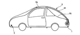
各添付図面において、本発明の保護防水シートシステムは、その全体を参照番号1で示す。本防水シートシステムは、モータービークル(自家用車または商用車、トラック、トレーラ、更にはボート)に接続、設置、追加または取り付けされるものである。本発明の防水シートシステムの用法としては、更に、任意の方法で動かせる可動物や更には建造物(例えば、貯水プール、水泳プールなど)まで覆うことも可能である。本発明を示す図1〜5において、防水シートシステムは自家用車タイプのモータービークルに取り付けられている。モータービークルVは従来の形のものであり、シャシーと、複数の車輪と、エンジンと、本体とを有する。そして、図1に見られるように、モータービークルVは更に、後部バンパPと、後部トランクMと、ルーフTと、前部フードCと、前部バンパとを有する。よって、本発明の防水シートシステムによる防水シートで覆われる対象となるモータービークル上部とは、後部トランクM、ルーフT、フードC、そして、後部バンパPおよび前部バンパRということになる。当然のことながら、防水シートシステムは更に、運転者および同乗者用のドアが位置するモータービークルVの側面についても、少なくとも部分的には覆う働きをする。結局、図4に示すように、本発明の防水シートシステムは、実際には、車輪と後部バンパの一部を除いて、車全体を覆う。ただし、これは1つの非限定的な実施の形態にすぎない。
Hereinafter, the present invention will be described in more detail with reference to the accompanying drawings showing two embodiments of the present invention as non-limiting examples.
In each accompanying drawing, the protective waterproof sheet system of the present invention is indicated by
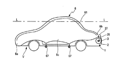
本発明の説明に用いる実施の形態において、本発明の防水シートシステム1は、図1〜5に見られるように、後部バンパPの内部に取り付けられる。防水シートシステム1については、後部バンパPの幅方向のほとんど全体にわたって広がる状態となるのが好ましい。ただし、これは非限定的な実施の形態を構成するにすぎない。本発明の防水シートシステムは、モータービークルVの他の個所、例えば、後部バンパPの外側、後部トランクMの上又は中、屋根Tの上、あるいは前部バンパRの外側又は内側などに設置することも可能だからである。一例として、本発明の防水シートシステムは、トレーラや移動住宅などの後部バンパPに取り外し可能な形で設置することが可能である。これは、例えば、据え付け装置をトレーラや移動住宅でなくシャシーに固定することで実現できる。当該据え付け装置は、防水シートシステムの設置を可能にする手段を含むものとする(スナップ留めで設置するものが効果的である)。本発明の防水シートシステムは、使用時にはモータービークルの後部に固定され、不使用時には、極めて簡単に車の内部(例えば、後部トランクの中)に格納することができる。つまり、本発明の防水シートシステムは、モータービークルでの任意の位置に配置できるキットの形となっている、と考えるべきである。また、ルーフラックなどの同等のシステムで、防水シートシステムをモータービークルの屋根Tに据え付けるようにすることも考えられる。本発明の防水シートシステムを取り外し可能とする場合は、当然、電気接続手段を設けて、モータービークル(通常はバッテリ)からの電力を用いて防水シートシステムに電気的動力を供給できるようにする必要がある。本発明の防水シートシステムをモータービークルに取り付けるにしろ、反対に取り外すにしろ、その構造および動作は実質的に同一または同等である。
In embodiment used for description of this invention, the
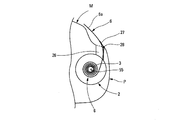
次いで、図6を参照する。同図は、本発明の保護防水シートシステムの全ての構成要素を概略的に示している。本防水シートシステムは容器2を含み、当該容器2の内部には、細長いスロット26によって外部に連通するハウジングが規定されている。一例としてではあるが、容器2は、ほぼ円形の断面を有し、その長さはモータービークルの幅よりも短い。そのため、図1〜5に示すように、容器2はモータービークルVの後部バンパPの内部に取り付けることができる。本防水シートシステムは更に巻き取りドラム3を有し、当該巻き取りドラム3は、細長いシャフト又はピンの形状になっており、その一方の端部に設置された電気モータ4の力によって、ドラム自体の軸を中心に回転するように作られている。ドラム3およびモータ4は、容器2の内部に格納される。ただし、図6において、これら要素は、分かりやすいように、容器2から引き出された状態で図示してある。ドラム3の他方の端部には空気注入手段5が装着されている。空気注入手段5はポンプまたはコンプレッサとすることができる。更に、本発明の範囲を逸脱することなしに、モータ4および空気注入手段5を別の場所(容器2の内部、更には外側)に据え付けることが可能である。巻き取りドラム3は更に、防水シート始動部31を備えている。当該防水シート始動部31の長さは、シートがドラム3から完全に引き出されるとスロット26から突き出た状態となるのに充分な長さとなっている。始動部31の自由端には、柔軟な防水シート6に設けられた相補的な接続端63につながれるファスナ端36が設けられている。一例として、柔軟な防水シート6は、一般に緊急用ブランケットに使用される素材から作ることができる。また、そうした素材の一例として、金属被覆加工(metal-plated)および/または銀被覆加工(silver-plated)したポリエステルを用いることができる。この種の素材は、相当な強度があり、極めて細いこと、そして、断熱性を有することで知られている。ただし、これは一例にすぎず、当然、本発明の防水シートは、何らかのフィルム、織布または不織布などで作ることも可能である。防水シートは、モータービークルの特定の部分(ナンバープレート、道路税支払済証など)が見えるよう透明とするのが好ましい。また、防水シートには、駐車利用券用のポケットを付けてもよい。また、始動部31を防水シート6と同じ素材で作ることにしてもよい。防水シート6を始動部31に接続する手段としては、例えば、接続端63およびファスナ端36をジッパーとすることもできる。当然、他の公知かつ従来型のファスナを使用することもできる。
Reference is now made to FIG. The figure schematically shows all the components of the protective tarpaulin system of the present invention. The tarpaulin system includes a
本発明では、柔軟な防水シート6は膨張式ホース61、62を備えており、当該膨張式ホースは、この非限定的な実施の形態では、U字形またはカップ形に延びている。「膨張式ホース」との用語は、内部の流体の圧力によって断面積が変化する柔軟なホースを意味すると理解すべきである。好ましい構成として、膨張式ホースは、流体の圧力を受けない状態では完全に平らであり、圧力を受けると断面が実質的に円形となる。こうした原理が当てはまる例として、消火ホースがある。本実施の形態では、防水シート6はU字形状の膨張式ホースを1つ有するものとする。ただし、変形例では、防水シート6に3つの中空ホース部を設け、2つの実質的に縦方向のホース部61が横方向接続ホース部62によって相互接続されている、という構成も考えられる。本実施の形態におけるホース部61は真っ直ぐで、モータービークルの長手方向と一致する縦方向Lにほぼ平行に延びている。ただし、留意すべき点として、ホース部61は縦方向Lに対して少し傾斜しており、その結果、2つのホース部61の自由端の間の間隔は、横方向接続ホース部62によって相互接続された反対側端部における間隔よりも広くなっている。
In the present invention, the
変形例では、2つのホース部61を完全に平行にしてもよいし、あるいは、反対向きに傾斜した形で延びることにしてもよい。また、ホース部61を真っ直ぐ以外の形(例えば、波打った形、カーブした形、ジグザグなど)とすることも可能である。ただし、ホース部61が縦方向Lの全体または大部分にわたって延びる形とすることが重要である。本発明の説明に用いる実施の形態では、2つの縦ホース部61が存在するが、よる多くの縦ホース部を設けることも、反対に縦ホース部を1つだけとすることもできる。図6の実施の形態は好適な実施の形態であるが、これに限定されるわけではない。本実施の形態では、膨張式ホースを、防水シート6の広く均一な範囲にわたって広がり、縦方向の範囲全体を覆う状態とすることが可能である。上記の通り、膨張式ホース61は、圧力の加えられた流体で膨張させることができる。流体は通常空気であるが、他の何らかの気体、更には液体であってもよい。そして、膨張を実現するために、防水シートは更に、膨張式ホース61を空気注入手段5に接続する供給管65を備える。より厳密に言えば、供給管65は、始動部31内に延びた接続管56に接続される形とすればよい。当該接続管はダクト55に接続しており、好ましい構成として、当該ダクトは巻き取りドラム3の内部を延びている。こうした構成により、空気注入手段5は膨張式ホースに接続される。従って、圧力の加わった流体がポンプ5から供給されると、膨張式ホースは膨張し、ある程度の剛性を有することになる。つまり、容易に理解されるであろうが、ホースの膨張によって柔軟な防水シート6を強化または硬くすることができる。そうなると、柔軟な防水シートはもはや可撓性の部材ではなく、実質的な硬さを持つプレートとして扱えるようになる。ホース部61を縦方向に向けることで、防水シート6を縦方向Lにおいて特に硬くすることができる。
In a modified example, the two
当然のことながら、縦方向のホース部61が2つ存在するという事実により、縦方向における強度は更に高められる。横方向ホース部62は、実際、2つの縦ホース部61を相互接続する以外の機能は有していない。効果的な構成として、供給管65が連結用ホース部62において膨張式ホースに接続されている点に留意すべきである。これにより、圧力の加わった流体は、防水シートの自由端6aにおいて、縦方向のホース部61に到達する。これらの特徴によって得られる効果については後述する。図示していない変形例では、供給管65をなくして、接続管56を防水シートの接続端6bに直接接続することも可能であり、その場合、ホースの膨張はドラム3に巻かれた状態の部分から始まる。
Naturally, the strength in the longitudinal direction is further increased by the fact that there are two
防水シートは、膨張式ホースに加え、複数の横方向弾性帯材66を有し、これらによって、防水シートを縦方向Lに対して垂直な方向に絞ることができる。また、防水シート6はループ67を備え、これによって、図1、4に見られるように、モータービークルに固定されたファスナフックFに防水シートの横方向で固定することができる。上記構成によって幅を狭くできるため、容器2のスロット26を通して巻き取りドラム3に巻き取ることが可能となる。スロット26の長さは防水シート6の幅よりも短いことが理解される。
In addition to the inflatable hose, the waterproof sheet includes a plurality of lateral
上述した通り、柔軟な防水シート6は1以上の膨張式ホース61、62を備えており、それらは連続的に接続されて一体化していてもよいし、あるいは反対に、互いから隔てられた形となっていてもよい。そして、やはり上述した通り、圧力を加えてホースを膨張させることでホースを硬化させ、そうすることで柔軟な防水シート6にある程度の剛性を与えることができる。言い換えると、膨張式ホースが防水シートを強化する補強手段を成しており、当該補強手段は、空気注入手段によって選択的に起動または休止させることができる。空気注入手段は補強部材に直接作用する起動機能を果たすことになる。補強部材の状態は、このように、実質的に剛性を有する起動状態と、実質的に柔らかいか可撓性である休止状態との間で選択的に切り替えることができる。本実施の形態では、2つの縦方向の補強部材61が、補強材連結部材62によって相互接続されている。しかしながら、圧力によるサイズの変化が生じない管のみを用いて連結部材62を作ることも、全く可能である。また、供給管65をY字形状のフォーク状部材とし、当該フォーク状部材を用いて、互いから完全に独立した2つの縦方向補強部材61に供給を行う、という構成を考えることも可能である。こうした構造では、連結部材62は不要となるであろう。
As mentioned above, the
本発明の防水シートシステムは更に、戻しバネを有する巻取機などの牽引装置Eを有することとしてもよい。こうした牽引装置はモータービークルの先頭に置かれる。牽引装置Eは、防水シートに手作業で接続される接続端部を有し、これは、防水シートをモータービークルの縦軸上に保持するためのものである。牽引装置Eの機能は、防水シートを引き出すことではなく、単に、引き出し作業中の防水シートが経路から外れるのを防止するだけである。よって、縦方向ガイド手段と考えることもできる。巻き取り作業中、牽引装置は不要である。 The waterproof sheet system of the present invention may further include a traction device E such as a winder having a return spring. These traction devices are placed at the front of the motor vehicle. The traction device E has a connection end that is manually connected to the waterproof sheet, for holding the waterproof sheet on the longitudinal axis of the motor vehicle. The function of the traction device E is not to pull out the waterproof sheet, but merely to prevent the waterproof sheet being pulled out of the path. Therefore, it can be considered as a longitudinal guide means. No traction device is required during the winding operation.
ここからは、再び図1〜4を参照しながら、自動車Vを防水シートで覆う作業のサイクル全体について説明する。図1、5では、モータービークルVの後部バンパPの内部に格納された容器2の内部に置かれた巻取ドラム3に、防水シート6のほとんど全部が巻き取られた状態が見て取れる。防水シート6は、その自由端6aだけがスロット26を通って容器2の外に突き出している。ここで、自由端6aはすでにトランクMの後端の位置にある。拡大図である図5では、スロット26が出口デフレクタ27を備えていることが見て取れる。出口デフレクタ27はモータービークルに向かって傾斜する方向に向けられており、これによって、防水シート6はモータービークル上部に向かって広がることになる。効果的な構成として、出口デフレクタ27は、位置28でスロット26にヒンジ留めされる形で設置されており、防水シートが容器2の内部に完全に巻き取られた状態にある時には、スロット26を閉じる閉じ蓋としての役割を果たす。当然のことながら、防水シートが容器2から、そしてスロット26から突き出た状態にできるような形で、自由端6aをスロット26の内部に保持する必要がある。出口デフレクタ27の駆動は、機械的に行っても電気的に行ってもよい。図1、5に示す状態は、デフレクタ27が動作状態に置かれた直後、防水シートの設置作業がまさしく開始される状況に対応しており、自由端6aが容器2から突出している。本質的には柔軟な防水シート6が自動的にスロット26から突出した状態にするために、起動/空気注入手段5を駆動して、圧力を加えた流体を膨張式ホースに注入する。これによって、少なくとも局所的には、柔軟な防水シート6を硬くすることができる。それによって、ある程度の堅さを有する状態となった防水シートが、スロット26から突出する。図1、5が示すのはこの状態である。当然、起動/空気注入手段5のスイッチを入れることは、ドラム3を回転させるモータ4を起動することを意味する。従って、膨張式ホースへの流体の注入と、防水シートのシャフト3からの引き出しとが同時に行われる。図2で示すように、防水シート6は、ホースは圧力が加わった状態にあることにより、ある程度の堅さを備えた状態で、継続して引き出されてモータービークルにかぶせられる。防水シート6は、出口デフレクタ27の作用で予め決められた方向に進むように強制されるため、モータービークルにかぶさる形で広げられることになる。その後、防水シートの引き出しと、ホース61の膨張とは、図3に示すように、防水シート6がモータービークルVを覆う状態になるまで続く。ここではまだ、防水シート6は作業完了状態にはないが、起動手段5およびモータ4は、この段階で停止してもよい。そうすると、ホース61は萎み、防水シートは本来の柔軟な状態に戻ることになる。その結果、防水シートは、モータービークルの外形にぴったりと合う状態になる。後は、ユーザがフックFにループ67を掛けて、自由端6aで前部バンパを覆うだけでよい。この状態を図4に示す。柔軟なホース61は再び平らになり、もはや防水シートに堅さを持たせることはない。なお、変形例では、ホースを膨張した状態に維持して、防水シートに渦巻き貝殻(rounded-shell)形状を持たせることもできる。
From here, the whole cycle of the operation | work which covers the motor vehicle V with a waterproof sheet is demonstrated, referring FIGS. 1-4 again. 1 and 5, it can be seen that almost all of the
防水シートの取り外しや巻き取りの作業は従来通りである。すなわち、モータ4のスイッチを入れて、ドラム3に防水シートを巻き取るだけでよい。起動/空気注入手段5は起動しない。この作業においては何の役割も果たさないからである。防水シートを容器2に完全に巻き取れば、後は、デフレクタの蓋27でスロット26を閉じるだけでよい。
膨張式ホースおよび供給管の向きをわずかに傾斜させることで、容器2内部のドラム3の厚みが大きくならない、という効果が生じる。当該ホースおよび管がわずかに傾斜していることにより、前記ホースおよび管は螺旋形の渦巻を成す形でドラム3に巻き付き、ホースおよび管自体が重なることはない。それによって、容器2の内部で過度に厚く重なる事態を防ぐことができる。こうした事態は、本発明の防水シートシステムの適正動作を妨げる原因となりうる。
The work of removing and winding the waterproof sheet is the same as before. That is, it is only necessary to turn on the
By slightly inclining the direction of the inflatable hose and the supply pipe, an effect that the thickness of the
防水シートには更に、ナンバープレートのコピー、透明ポケット、太陽光電池などの付属品を設けてもよい。
モータ4および空気注入手段5への電力供給には、車載バッテリーまたは専用バッテリーを用いる。太陽光電池で発電してもよい。
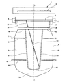
ここからは、図7を参照しながら、図6の第1の実施の形態の変形例について説明する。同図の変形例における防水シートシステムはやはり、スロット26を備えた容器2、巻き取りドラム3、モータ4、空気注入手段5、ドラム3に巻き取り可能な柔軟な防水シート6、2つの膨張式ホース61、そして2つの供給管65から成る。これらの構成要素は、図6の実施の形態における構成要素と類似または同一である。しかし、本変形例の実施の形態と図6の実施の形態とは、膨張式ホース61が防水シート6の中に組み入れられているのでなく、防水シート6の両側に置かれて、自由端においてのみ複数の留め具68によって柔軟な防水シート6につながれている、という点で異なっている。柔軟な防水シート6は、留め具68同士の間隔を維持するためにスペーサ62´を備えることとしてもよく、スペーサ62´は横軸補強材の役割を果たす。2つの膨張式ホース61は、図6の実施の形態と同様に、ドラム3に巻き取ることができる。ただし、図6における膨張式ホース61が防水シート6に組み入れられているのに対し、図7における膨張式ホース61は、留め具68以外では防水シート6から分離している。そのため、膨張式ホース61は防水シート6とは別にシャフト3に巻かれる。より厳密に言えば、図7に見られるように、容器2は複数の区画21、22、23に細分化され、それら全てを巻き取りドラム3が貫通する形となっている。中心の区画21は最大であり、防水シート6を収容するためのものである。区画21の両側には、柔軟な膨張式ホース61を収容するための側部区画22が1つずつある。最後に、その外側には、柔軟な供給管65を収容する2つの区画23があり、供給管65もシャフト3に直接巻かれる。図6の場合のように防水シート6、膨張式ホース61および/または供給管65を一緒に巻き取る場合に比べて、図7の変形例の実施の形態は、上記構成要素の全てを別々に巻き取ることから、厚みが増して容器2のサイズや小型化の問題に関して悪影響を生じる事態は回避されると考えられる。こうした構造によって、容器2の直径をかなり抑えることができる。容器2の長さは少し大きくなるが、区画22、23はあまり広くする必要がないため、長さの増加は最小限となる。
The waterproof sheet may be further provided with accessories such as a copy of a license plate, a transparent pocket, and a solar battery.
For power supply to the
From here, the modification of 1st Embodiment of FIG. 6 is demonstrated, referring FIG. The tarpaulin system in the modified example of the figure also has a
更に、本変形例の実施の形態の別の効果的な特徴として、防水シートシステムはガイド手段7を備え、当該ガイド手段7は引き出し作業中の帯材61を縦方向にガイドする。帯材を正しく巻くためには、防水シートを完全にガイドして、わずかでも横方向に逸脱しないようにすることが好ましい。一例として、ガイド手段は区画22に収容することができる。また、一例として、ガイド手段は、2つの押圧ローラ71、72から成り、互いに対して押し付けられることで、局所的な挟み付けを実現する、という構成にすることもできる。帯材61は2つの押圧ローラ71、72の間を通り、これらによってガイドされるため、何もホースの中を流れることはできない。こうして、2つの押圧ローラ71、72によって、空気を通さない形での局所的な挟み付けが行われるため、ホースのうち区画22の内部でドラム3に巻かれた部分が膨張することはない。圧力の加わった空気はホースのこの部分には入り込めないからである。この状態を図8(a)に概略的に示す。図8(b)、(c)は、非常に概略的であるが、区画21、23それぞれの内部に置ける防水シート6、供給管65の形状を示している。留意すべき点として、こうした、空気を通さない形で局所的に挟み付ける装置7は、図6の実施の形態にも使用することができるであろう。
Furthermore, as another effective feature of the embodiment of the present modification, the waterproof sheet system includes guide means 7, and the guide means 7 guides the
図7の防水シートシステムの動作は、図6の防水シートシステムの動作に類似している。防水シートでモータービークルを覆いたい場合には、モータ4と空気注入手段5とを両方とも駆動して、防水シート6をドラム3から引き出し、膨張式ホース61を供給管65を介して膨張させる。留意すべき点として、膨張式ホース61の膨張は、それら自体をドラム3から引き出すのに役立つ。ホース61のうち、すでに膨張して区画22の外にある部分は、留め具68の位置でつながれていることから、防水シート6に剛性を与え、これを動かす。図6の実施の形態と同様に、防水シート6と膨張したホース61とは、例えばデフレクタ27などの手段によって、適切な形で向きを変えられ、それによって、防水シートはモータービークル上部に向けて送られることになる。防水シートをかぶせる作業が終了すると、モータ4および空気注入手段5は停止される。上述したのと同様に、ユーザは手作業で、モータービークルに防水シートを固定する作業を終えることができる。また、防水シートを取り外す作業は、上述した作業と全く同一である。モータ4を駆動して防水シート6、膨張したホース61そして供給管65を巻き取りドラム3に巻き取る。ただし、これらは、前述した別々の区画に巻き取られる。防水シートの取り外し作業が終わった時も、防水シート6と、萎んだホース61と、供給管65とは、スペーサ62´の位置で留め具68を介して接続されて一体の状態を保っている。
The operation of the waterproof sheet system of FIG. 7 is similar to the operation of the waterproof sheet system of FIG. When it is desired to cover the motor vehicle with the waterproof sheet, both the
図9、10は好適な実施の形態を示す。この実施の形態は、既に述べた実施の形態と、以下の特徴によって異なっている:
・防水シートの一方の側部だけに沿って延びた後、横方向に延びて反対側の膨張式ホース61に接続している横方向供給管65;
・太陽電池で覆われた領域Zが形成されており、モータービークルが特に電気自動車である場合に、当該モータービークルが使用する電気の全部または一部を発生させる、という防水シート;
・ホースまたは帯材61に合わせて形状加工された2つの押圧ローラ71、72から成り、ホースまたは帯材61のガイドおよび局所的な挟み付けの状態を向上させるガイド手段7。
9 and 10 show a preferred embodiment. This embodiment differs from the previously described embodiment by the following features:
A
A waterproof sheet in which a region Z covered with solar cells is formed and generates all or part of the electricity used by the motor vehicle, particularly when the motor vehicle is an electric vehicle;
A guide means 7 comprising two
ここからは、図11、12、13を参照しながら第2の実施の形態について説明する。第2の実施の形態と既に述べた実施の形態との主要な差異は、膨張式ホースを補強部材として使用しない点である。本実施の形態における補強部材61´は、防水シート6の両側に延びた巻き取り可能な帯材の形をしている。図7に示した実施の形態の場合と同様、帯材61´は、スペーサ62´の近傍の留め具68によって、防水シート6の自由端につながれている。言い換えると、帯材61´は留め具68によってのみ防水シートにつながっている。一例として、巻き取り可能な帯材61´は、形状加工された金属片の形を取り、引き出された状態では真っ直ぐかつ硬い状態で延びている一方、巻き取り可能な性質も持つ。こうした帯材は、具体的には巻尺の用途で、従来技術においても公知である。帯材をわずかに凹形とすることで、引き出された状態ではある程度の剛性を持たせることができる一方で、巻き取り可能とすることもできる。本発明に関しては、一例として、スプリングの力で巻き取りドラム3とは別個の専用巻き取りシャフト83に巻き付けられて巻き取り状態となる、という巻き取り可能な帯材61´を用いることも可能である。この巻き取り状態を図12に示す。一例として、帯材61´は、従来の巻尺と同様のケース8に格納することにしてもよい。帯材61´をそのケース8から引き出すために、本発明は巻き取りドラム3の駆動力を用いる巧妙な駆動システムを提供する。より厳密に言えば、受けローラ9が帯材61´をシャフト3に押し付け、シャフト3が帯材61´を引っ張るようにする。効果的な構成としては、帯材61´の面と、ドラム3のうち帯材61´と接触する部分とに刻みを設けて、ラックピニオン型の駆動力を生じさせればよい。こうして、受けローラ9によって、帯材61´とドラム3とを確実に良好な状態で噛み合わせることができる。当然のことながら、受けローラ9の代わりに、帯材61´とドラム3との間に効果的接触を保証できる、他の何らかの装置を設けることも可能である。
From here, the second embodiment will be described with reference to FIGS. The main difference between the second embodiment and the embodiment already described is that the inflatable hose is not used as a reinforcing member. Reinforcing
図7の変形例の実施の形態と同様に、容器2は複数の区画21、24に分割されている。中央の区画21は巻き取られた防水シート6を収容し、側部の区画24は、巻き取られた帯材が入ったケース8と受けローラ9とを収容する。
図13に示す変形例における防水シートシステムは、2つのローラ71´、72´になったガイド手段を有し、これらローラの間を帯材61´が通過し、ガイドされる。より厳密に言えば、ローラ71´には2列のスプロケット75が形成されており、これらが第2のローラ72´に形成された2列の窪み76に嵌る。帯材61´は、映画用フィルムに類似した2列の側面パーフォレーション(貫通孔)を備える形に作られており、その孔にスプロケット75が嵌ることで帯材61´は移動させられる。ローラの回転のために、車輪73、33とベルト74とを有する駆動システムを介して、ローラ72´をドラム3に連結する。
Similar to the modified embodiment of FIG. 7, the
The waterproof sheet system in the modified example shown in FIG. 13 has guide means that are two
この第2の実施の形態の効果は、一緒に空気注入手段を使用する必要がない点であり、同時に帯材および防水シートを巻き取ること、引き出すことを可能にする駆動モータ4が、唯一の電気部品である。
実施の形態の全てにおいて、補強部材61、61´は、モータを用いて、ドラム3に直接巻き取ること、または、シャフト83などの別個のシャフトに巻き取ること、が可能である。留意すべき点として、補強部材は、巻き取り状態においては全く補強機能を発揮せず、2つの完全に異なる状態を使い分けている。
The effect of this second embodiment is that it is not necessary to use air injection means together, and the
In all of the embodiments, the reinforcing
本発明によれば、柔軟な防水シートが有する補強手段は、防水シートをかぶせる作業、または防水シートを引き出す作業の間しか作用せず、防水シートを取り外す作業、または防水シートを巻き取る作業の間は、全く機能せず、目にも見えない。 According to the present invention, the reinforcing means of the flexible waterproof sheet acts only during the operation of covering the waterproof sheet or the operation of pulling out the waterproof sheet, and during the operation of removing the waterproof sheet or winding up the waterproof sheet. Does not work at all and is invisible.
Claims (13)
少なくとも部分的にはモータービークル(V)を覆って保護する柔軟な防水シート(6)を有し、
防水シート(6)にはモータービークル上を長さ方向に進む方向である縦方向(L)が定められており、防水シート(6)は前記縦方向(L)に延びる1以上の補強部材(61; 61´)を備え、当該補強部材(61; 61´)は柔軟な防水シートに縦方向の剛性をもたらすことで、モータービークルを防水シートで覆う作業を容易にし、
効果的な構成としてモータービークルの後部バンパに設置された巻き取りドラム(3)を更に有し、防水シート(6)は巻き取りドラム(3)に巻き取り可能であって、巻き取りドラム(3)によって巻き取り状態または引き出し状態とされ、
前記1以上の補強部材(61; 61´)は、巻き取りドラム(3)に対して垂直な方向に延びており、巻き取りドラム(3)または当該巻き取りドラム(3)とは別個の巻き取りシャフト(83)に巻き取りが可能であって、
巻き取りドラム(3)をそれ自体の軸を中心に回転させるモータ(4)を更に有すること、
を特徴とする保護防水シートシステム。 As an example, a protective tarpaulin system (1) used for a motor vehicle (V) including a passenger car,
A flexible tarpaulin (6) at least partially covering and protecting the motor vehicle (V);
The waterproof sheet (6) has a longitudinal direction (L) that is a longitudinal direction on the motor vehicle, and the waterproof sheet (6) has one or more reinforcing members (in the longitudinal direction (L)). 61; 61 '), and the reinforcing member (61; 61') provides a flexible waterproof sheet with longitudinal rigidity to facilitate the work of covering the motor vehicle with the waterproof sheet,
As an effective configuration, it further has a winding drum (3) installed on the rear bumper of the motor vehicle, and the waterproof sheet (6) can be wound around the winding drum (3). ) To be in the winding state or the drawing state,
The one or more reinforcing members (61; 61 ') extend in a direction perpendicular to the take-up drum (3), and are wound separately from the take-up drum (3) or the take-up drum (3). The take-up shaft (83) can be wound up,
Further comprising a motor (4) for rotating the winding drum (3) about its own axis;
Protective tarpaulin system characterized by.
を特徴とする請求項1に記載の保護防水シートシステム。 Further comprising guide means (7; E) for longitudinally guiding the one or more reinforcing members during winding or drawing;
The protective waterproof sheet system according to claim 1.
を特徴とする請求項2に記載の保護防水シートシステム。 The guide means (7) is composed of two rotating pressure rollers (71, 72), and the reinforcing member being wound or pulled out passes between the two rotating pressure rollers (71, 72).
The protective waterproof sheet system according to claim 2.
前記1以上の補強部材(61)は、圧力の加わった流体で膨張させられる膨張式ホースから成り、
起動手段は、ポンプまたはコンプレッサである空気注入手段(5)から成り、前記1以上の補強部材(61)とは流体による連通状態であること、
を特徴とする請求項1乃至3のいずれか一項に記載の保護防水シートシステム。 The one or more reinforcing members (61) are provided with starting means (5), and the starting means (5) acts on the reinforcing member (61) to change the state of the reinforcing member (61) to the reinforcing member ( 61) selectively switching between a rigid activated state and a resting state in which the reinforcing member (61) is soft,
The one or more reinforcing members (61) are composed of an inflatable hose that is inflated with a fluid under pressure,
The starting means comprises air injecting means (5) which is a pump or a compressor, and is in fluid communication with the one or more reinforcing members (61).
The protective waterproof sheet system according to any one of claims 1 to 3, wherein:
前記1以上の補強部材(61)は自由端(6a)と接続端(6b)との間に延びており、
空気注入手段(5)は供給管(65)を介して前記1以上の補強部材(61)に接続されており、供給管(65)は自由端(6a)の近傍で前記補強部材(61)に接続されており、それによって、前記補強部材(61)は自由端から接続端(6b)にむかって膨張していくこと、
を特徴とする請求項4に記載の保護防水シートシステム。 The waterproof sheet (6) has a free end (6a) that covers the front of the motor vehicle, and a connection end (6b) that is fixed to the winding drum (3).
The one or more reinforcing members (61) extend between a free end (6a) and a connecting end (6b);
The air injection means (5) is connected to the one or more reinforcing members (61) via a supply pipe (65), and the supply pipe (65) is connected to the reinforcing member (61) in the vicinity of the free end (6a). Whereby the reinforcing member (61) expands from the free end to the connecting end (6b),
The protective waterproof sheet system according to claim 4.
を特徴とする請求項5に記載の保護防水シートシステム。 The guide means (7) is composed of two rotary pressing rollers (71, 72), and the rotary pressing rollers (71, 72) locally sandwich the inflatable hose being pulled out to prevent air from passing therethrough. By preventing the portion of the inflatable hose wound around the winding drum (3) from expanding,
The protective waterproof sheet system according to claim 5.
を特徴とする請求項5又は6に記載の保護防水シートシステム。 The waterproof sheet (6), the reinforcing member (61), and the supply pipe can be separately wound around the winding drum (3), thereby preventing the thickness in the winding state from becoming excessively large. To do,
The protective waterproof sheet system according to claim 5 or 6.
を特徴とする請求項1乃至3のいずれか一項に記載の保護防水シートシステム。 The one or more reinforcing members are made of a strip material (61 ') that is straight and hard when pulled out;
The protective waterproof sheet system according to any one of claims 1 to 3, wherein:
を特徴とする請求項8に記載の保護防水シートシステム。 The strip (61 ′) is wound around a dedicated winding shaft (83) extending in parallel with the winding drum (3), and the strip is pulled out by the winding drum,
The protective waterproof sheet system according to claim 8.
を特徴とする請求項1乃至9のいずれか一項に記載の保護防水シートシステム。 The one or more reinforcing members (61, 61 ') are connected to the waterproof sheet (6) only at the free end (6a) covering the front portion of the motor vehicle, and the reinforcing member and the waterproof sheet can be wound separately. Being possible,
The protective waterproof sheet system according to any one of claims 1 to 9, wherein:
を特徴とする請求項1乃至10のいずれか一項に記載の保護防水シートシステム。 The drum (3) is stored in a container (2) installed in the rear bumper of the motor vehicle, the container (2) has an elongated slot (26) through which a waterproof sheet (6) can pass, The slot (26) comprises an outlet deflector (27) made to direct the waterproof sheet (6) to the top of the motor vehicle while the tarpaulin is being pulled out, the outlet deflector (27) Functioning as a pivoting closure lid for closing (26);
The protective waterproof sheet system according to any one of claims 1 to 10, wherein:
を特徴とする請求項1乃至11のいずれか一項に記載の保護防水シートシステム。 The guide means comprises a traction device (E) located at the front of the motor vehicle, and is connected to the waterproof sheet (6) to guide the waterproof sheet in the vertical direction.
The protective waterproof sheet system according to any one of claims 1 to 11, wherein:
を特徴とする請求項1乃至12のいずれか一項に記載の保護防水シートシステム。 The waterproof sheet (6) has a region (Z) covered with solar cells,
The protective waterproof sheet system according to any one of claims 1 to 12, wherein:
Applications Claiming Priority (3)
| Application Number | Priority Date | Filing Date | Title |
|---|---|---|---|
| FR0954642A FR2947489B1 (en) | 2009-07-06 | 2009-07-06 | PROTECTION SHEET SYSTEM FOR MOTOR VEHICLE. |
| FR0954642 | 2009-07-06 | ||
| PCT/FR2010/051406 WO2011004105A1 (en) | 2009-07-06 | 2010-07-05 | Protective covering system for a motor vehicle |
Publications (1)
| Publication Number | Publication Date |
|---|---|
| JP2012532066A true JP2012532066A (en) | 2012-12-13 |
Family
ID=41665529
Family Applications (1)
| Application Number | Title | Priority Date | Filing Date |
|---|---|---|---|
| JP2012519038A Pending JP2012532066A (en) | 2009-07-06 | 2010-07-05 | Protective tarpaulin system for motor vehicle |
Country Status (7)
| Country | Link |
|---|---|
| US (1) | US20120146358A1 (en) |
| EP (1) | EP2451666A1 (en) |
| JP (1) | JP2012532066A (en) |
| CN (1) | CN102481830A (en) |
| FR (2) | FR2947489B1 (en) |
| IN (1) | IN2012DN00922A (en) |
| WO (1) | WO2011004105A1 (en) |
Families Citing this family (21)
| Publication number | Priority date | Publication date | Assignee | Title |
|---|---|---|---|---|
| ITRM20120244A1 (en) * | 2012-05-28 | 2013-11-29 | Claudio Crudi | ROLLER COVER FOR MOTOR VEHICLE COVERING. |
| CN102729788A (en) * | 2012-07-09 | 2012-10-17 | 滕曙 | Car sunshade |
| CN202986781U (en) * | 2012-12-19 | 2013-06-12 | 殷月伟 | Automatic sealing shield for automobiles |
| ITUD20130004A1 (en) * | 2013-01-18 | 2014-07-19 | Paolo Malavasi | PROTECTIVE DEVICE FOR VEHICLES |
| FR3002496B1 (en) | 2013-02-25 | 2015-04-03 | Andre Sassi | MOTOR VEHICLE HAVING A PROTECTION TANK SYSTEM. |
| AR092109A1 (en) * | 2013-08-13 | 2015-03-25 | Basilio Lichowski Ricardo | SOLAR PROTECTOR AND AUTOMATIC ANTIGRANIZE SHIELD |
| US9004088B1 (en) * | 2013-09-25 | 2015-04-14 | Eduardo Nicheporuck | Protective canopy and method |
| FR3012770A3 (en) * | 2013-11-04 | 2015-05-08 | Renault Sa | "VEHICLE COMPRISING A FLEXIBLE INTEGRATED COVER ELEMENT" |
| CN104442325B (en) * | 2014-12-09 | 2016-05-11 | 东莞市卡尔仕家居用品设计有限公司 | Full-automatic sunshade gas hood |
| CN104691293A (en) * | 2015-03-21 | 2015-06-10 | 沈国定 | Electric folding and winding type automotive cover |
| US9533558B2 (en) * | 2015-05-20 | 2017-01-03 | Ted Justin Suh | Automatic vehicle cover |
| EP3106332B1 (en) * | 2015-06-18 | 2020-04-15 | Universita' degli studi di Bergamo | Inflatable tubular element for laying protective tarpaulins |
| CN104943519A (en) * | 2015-06-29 | 2015-09-30 | 凯撒尔·麦麦提 | Automobile sunscreen and snow protection remote control invisible windshield cover |
| US9908394B2 (en) * | 2016-07-07 | 2018-03-06 | Ford Global Technologies, Llc | Protective cover system and related method |
| CN106564416B (en) * | 2016-10-19 | 2018-11-09 | 江苏理工学院 | Caravan automatic sun shade awning |
| SG10201703175SA (en) * | 2017-02-24 | 2018-09-27 | Sadek Ismail Hadi | Vehicle cover with accessories |
| FR3066443B1 (en) | 2017-05-22 | 2021-01-15 | Andre Sassi | AUTOMOTIVE VEHICLE PROVIDED WITH A PROTECTION COVER SYSTEM. |
| US10787068B2 (en) | 2017-07-31 | 2020-09-29 | Michael A. Cassidy | Retractable car cover |
| DE102019100472A1 (en) * | 2019-01-10 | 2020-07-16 | Ralph Krueger | Functional roof covering for campers |
| US11554652B2 (en) * | 2020-03-09 | 2023-01-17 | Bessie NEWELL | Integrated cover |
| CN113479045A (en) * | 2021-08-11 | 2021-10-08 | 重庆江北区长安产业有限公司 | Waterproof and dustproof cover for automobile |
Family Cites Families (12)
| Publication number | Priority date | Publication date | Assignee | Title |
|---|---|---|---|---|
| DE1051142B (en) * | 1958-01-28 | 1959-02-19 | Hermann Kempf Dipl Ing | Protective cover, especially for cars |
| DE2747603A1 (en) * | 1977-10-24 | 1979-04-26 | Mario Tabri | Pneumatic or hydraulic support for vehicle cover - with support reed pattern linked to fluid pump |
| US4432581A (en) * | 1982-01-04 | 1984-02-21 | Tesfa Guma | Portable automatic carport |
| US5242206A (en) * | 1992-08-31 | 1993-09-07 | Heck Bernard J | Automotive hail blanket |
| CN1076675C (en) * | 1996-07-09 | 2001-12-26 | 张力 | Automatic collapsible sunshade for vehicles |
| US5902003A (en) * | 1997-01-10 | 1999-05-11 | Hindson; Thomas William | Motor vehicle cover with low profile housing and inflatable side chambers |
| US6044881A (en) * | 1998-10-28 | 2000-04-04 | Welch; Robert E. | Protective hail cover for vehicles |
| US6981509B2 (en) * | 2003-09-11 | 2006-01-03 | Sergey Sharapov | Protective cover for a vehicle |
| DE102005024657C5 (en) * | 2004-11-19 | 2016-04-21 | Webasto Ag | Roller blind arrangement for a vehicle |
| US20060232095A1 (en) * | 2005-04-13 | 2006-10-19 | Marty Sedighzadeh | Retractable roll-up cover |
| EP1878601A1 (en) * | 2006-07-14 | 2008-01-16 | Veamo | A vehicle protection device. |
| US7464982B1 (en) * | 2007-01-10 | 2008-12-16 | Xiaogu Lin | Vehicle protecting cover device |
-
2009
- 2009-07-06 FR FR0954642A patent/FR2947489B1/en not_active Expired - Fee Related
-
2010
- 2010-07-05 JP JP2012519038A patent/JP2012532066A/en active Pending
- 2010-07-05 CN CN2010800374211A patent/CN102481830A/en active Pending
- 2010-07-05 WO PCT/FR2010/051406 patent/WO2011004105A1/en active Application Filing
- 2010-07-05 US US13/382,461 patent/US20120146358A1/en not_active Abandoned
- 2010-07-05 IN IN922DEN2012 patent/IN2012DN00922A/en unknown
- 2010-07-05 EP EP10742191A patent/EP2451666A1/en not_active Withdrawn
-
2011
- 2011-01-04 FR FR1150034A patent/FR2962260A1/en not_active Withdrawn
Also Published As
| Publication number | Publication date |
|---|---|
| EP2451666A1 (en) | 2012-05-16 |
| CN102481830A (en) | 2012-05-30 |
| FR2962260A1 (en) | 2012-01-06 |
| WO2011004105A1 (en) | 2011-01-13 |
| US20120146358A1 (en) | 2012-06-14 |
| FR2947489B1 (en) | 2011-10-28 |
| IN2012DN00922A (en) | 2015-04-03 |
| FR2947489A1 (en) | 2011-01-07 |
Similar Documents
| Publication | Publication Date | Title |
|---|---|---|
| JP2012532066A (en) | Protective tarpaulin system for motor vehicle | |
| JP2016507421A (en) | Motor vehicle with protective tarpaulin system | |
| US5823610A (en) | Drag reducing apparatus for a vehicle | |
| US4432581A (en) | Portable automatic carport | |
| US5902003A (en) | Motor vehicle cover with low profile housing and inflatable side chambers | |
| TWI445636B (en) | Car cover | |
| US20060197317A1 (en) | Airbag attachment structure | |
| US20040238089A1 (en) | Self coiling roll-up car cover | |
| EP2046595B1 (en) | A vehicle protection device | |
| JP4209422B2 (en) | Body cover | |
| CN101585312A (en) | On-vehicle automatic winding automotive sun-shading anti-dust device | |
| CN212827841U (en) | Carriage cover locking mechanism and automobile | |
| ITMI20062116A1 (en) | PROPERTY ROOF FOR MEANS OF TRANSPORT IN PARTICULAR CAMPER | |
| US20070074829A1 (en) | Window shade | |
| CN206968372U (en) | Wheel guard apparatus and vehicle | |
| CN213108952U (en) | Portable telescopic vehicle cover | |
| KR102659087B1 (en) | Auto screen apparatus for car window | |
| KR20180105528A (en) | Automatic spread waterproofed canvas for automobile | |
| KR100295254B1 (en) | Automatic car-cover | |
| JPS5846890Y2 (en) | Automotive top protection device | |
| KR200264644Y1 (en) | Sunshield device for automobile | |
| JP2000118245A (en) | Window glass cover for automobile | |
| KR200468103Y1 (en) | Opening and closing apparatus for the cover of the vehicle | |
| JPH0396433A (en) | Automotive cover device | |
| CN112384396A (en) | Vehicle hail protection |