JP2012531717A - Battery structure manufacturing method - Google Patents
Battery structure manufacturing method Download PDFInfo
- Publication number
- JP2012531717A JP2012531717A JP2012518028A JP2012518028A JP2012531717A JP 2012531717 A JP2012531717 A JP 2012531717A JP 2012518028 A JP2012518028 A JP 2012518028A JP 2012518028 A JP2012518028 A JP 2012518028A JP 2012531717 A JP2012531717 A JP 2012531717A
- Authority
- JP
- Japan
- Prior art keywords
- electrochemical cell
- jacket
- frame
- joint
- battery structure
- Prior art date
- Legal status (The legal status is an assumption and is not a legal conclusion. Google has not performed a legal analysis and makes no representation as to the accuracy of the status listed.)
- Pending
Links
Images


Classifications
-
- H—ELECTRICITY
- H01—ELECTRIC ELEMENTS
- H01M—PROCESSES OR MEANS, e.g. BATTERIES, FOR THE DIRECT CONVERSION OF CHEMICAL ENERGY INTO ELECTRICAL ENERGY
- H01M50/00—Constructional details or processes of manufacture of the non-active parts of electrochemical cells other than fuel cells, e.g. hybrid cells
- H01M50/20—Mountings; Secondary casings or frames; Racks, modules or packs; Suspension devices; Shock absorbers; Transport or carrying devices; Holders
- H01M50/258—Modular batteries; Casings provided with means for assembling
- H01M50/26—Assemblies sealed to each other in a non-detachable manner
-
- H—ELECTRICITY
- H01—ELECTRIC ELEMENTS
- H01M—PROCESSES OR MEANS, e.g. BATTERIES, FOR THE DIRECT CONVERSION OF CHEMICAL ENERGY INTO ELECTRICAL ENERGY
- H01M50/00—Constructional details or processes of manufacture of the non-active parts of electrochemical cells other than fuel cells, e.g. hybrid cells
- H01M50/10—Primary casings, jackets or wrappings of a single cell or a single battery
- H01M50/102—Primary casings, jackets or wrappings of a single cell or a single battery characterised by their shape or physical structure
- H01M50/105—Pouches or flexible bags
-
- H—ELECTRICITY
- H01—ELECTRIC ELEMENTS
- H01M—PROCESSES OR MEANS, e.g. BATTERIES, FOR THE DIRECT CONVERSION OF CHEMICAL ENERGY INTO ELECTRICAL ENERGY
- H01M50/00—Constructional details or processes of manufacture of the non-active parts of electrochemical cells other than fuel cells, e.g. hybrid cells
- H01M50/10—Primary casings, jackets or wrappings of a single cell or a single battery
- H01M50/116—Primary casings, jackets or wrappings of a single cell or a single battery characterised by the material
- H01M50/121—Organic material
-
- H—ELECTRICITY
- H01—ELECTRIC ELEMENTS
- H01M—PROCESSES OR MEANS, e.g. BATTERIES, FOR THE DIRECT CONVERSION OF CHEMICAL ENERGY INTO ELECTRICAL ENERGY
- H01M50/00—Constructional details or processes of manufacture of the non-active parts of electrochemical cells other than fuel cells, e.g. hybrid cells
- H01M50/10—Primary casings, jackets or wrappings of a single cell or a single battery
- H01M50/116—Primary casings, jackets or wrappings of a single cell or a single battery characterised by the material
- H01M50/124—Primary casings, jackets or wrappings of a single cell or a single battery characterised by the material having a layered structure
-
- H—ELECTRICITY
- H01—ELECTRIC ELEMENTS
- H01M—PROCESSES OR MEANS, e.g. BATTERIES, FOR THE DIRECT CONVERSION OF CHEMICAL ENERGY INTO ELECTRICAL ENERGY
- H01M50/00—Constructional details or processes of manufacture of the non-active parts of electrochemical cells other than fuel cells, e.g. hybrid cells
- H01M50/20—Mountings; Secondary casings or frames; Racks, modules or packs; Suspension devices; Shock absorbers; Transport or carrying devices; Holders
- H01M50/204—Racks, modules or packs for multiple batteries or multiple cells
- H01M50/207—Racks, modules or packs for multiple batteries or multiple cells characterised by their shape
- H01M50/211—Racks, modules or packs for multiple batteries or multiple cells characterised by their shape adapted for pouch cells
-
- H—ELECTRICITY
- H01—ELECTRIC ELEMENTS
- H01M—PROCESSES OR MEANS, e.g. BATTERIES, FOR THE DIRECT CONVERSION OF CHEMICAL ENERGY INTO ELECTRICAL ENERGY
- H01M50/00—Constructional details or processes of manufacture of the non-active parts of electrochemical cells other than fuel cells, e.g. hybrid cells
- H01M50/50—Current conducting connections for cells or batteries
- H01M50/543—Terminals
- H01M50/552—Terminals characterised by their shape
- H01M50/553—Terminals adapted for prismatic, pouch or rectangular cells
- H01M50/557—Plate-shaped terminals
-
- Y—GENERAL TAGGING OF NEW TECHNOLOGICAL DEVELOPMENTS; GENERAL TAGGING OF CROSS-SECTIONAL TECHNOLOGIES SPANNING OVER SEVERAL SECTIONS OF THE IPC; TECHNICAL SUBJECTS COVERED BY FORMER USPC CROSS-REFERENCE ART COLLECTIONS [XRACs] AND DIGESTS
- Y02—TECHNOLOGIES OR APPLICATIONS FOR MITIGATION OR ADAPTATION AGAINST CLIMATE CHANGE
- Y02E—REDUCTION OF GREENHOUSE GAS [GHG] EMISSIONS, RELATED TO ENERGY GENERATION, TRANSMISSION OR DISTRIBUTION
- Y02E60/00—Enabling technologies; Technologies with a potential or indirect contribution to GHG emissions mitigation
- Y02E60/10—Energy storage using batteries
-
- Y—GENERAL TAGGING OF NEW TECHNOLOGICAL DEVELOPMENTS; GENERAL TAGGING OF CROSS-SECTIONAL TECHNOLOGIES SPANNING OVER SEVERAL SECTIONS OF THE IPC; TECHNICAL SUBJECTS COVERED BY FORMER USPC CROSS-REFERENCE ART COLLECTIONS [XRACs] AND DIGESTS
- Y02—TECHNOLOGIES OR APPLICATIONS FOR MITIGATION OR ADAPTATION AGAINST CLIMATE CHANGE
- Y02P—CLIMATE CHANGE MITIGATION TECHNOLOGIES IN THE PRODUCTION OR PROCESSING OF GOODS
- Y02P70/00—Climate change mitigation technologies in the production process for final industrial or consumer products
- Y02P70/50—Manufacturing or production processes characterised by the final manufactured product
-
- Y—GENERAL TAGGING OF NEW TECHNOLOGICAL DEVELOPMENTS; GENERAL TAGGING OF CROSS-SECTIONAL TECHNOLOGIES SPANNING OVER SEVERAL SECTIONS OF THE IPC; TECHNICAL SUBJECTS COVERED BY FORMER USPC CROSS-REFERENCE ART COLLECTIONS [XRACs] AND DIGESTS
- Y10—TECHNICAL SUBJECTS COVERED BY FORMER USPC
- Y10T—TECHNICAL SUBJECTS COVERED BY FORMER US CLASSIFICATION
- Y10T156/00—Adhesive bonding and miscellaneous chemical manufacture
- Y10T156/10—Methods of surface bonding and/or assembly therefor
Abstract
少なくとも一つの第一の電気化学セル(102,202,…)と、少なくとも一つの第二の電気化学セル(102,202,…)とを含むバッテリー構造体(101,201,…)を製造するための方法であり、個々の電気化学セルがジャケット(103,203,…)を有している方法において、前記第一の電気化学セル(102,202,…)の前記ジャケット(103,203,…)のジャケット部分(104,204,…)は、前記第二の電気化学セル(102,202,…)の前記ジャケット(103,203,…)のジャケット部分(104,204,…)と材料接続的に接合されることを特徴とする方法。 A battery structure (101, 201, ...) including at least one first electrochemical cell (102, 202, ...) and at least one second electrochemical cell (102, 202, ...) is manufactured. In which each electrochemical cell has a jacket (103, 203,...), The jacket (103, 203,...) Of the first electrochemical cell (102, 202,...). ...) of the jacket part (104, 204, ...) and the jacket part (104, 204, ...) of the jacket (103, 203, ...) of the second electrochemical cell (102, 202, ...). A method characterized by being connected in a connected manner.
Description
本発明はバッテリー構造体を製造するための方法に関する。本発明はまた、バッテリー構造体を製造するために用いられる電気化学セルと、当該方法によって製造されたバッテリー構造体に関する。 The present invention relates to a method for manufacturing a battery structure. The invention also relates to an electrochemical cell used to produce a battery structure and a battery structure produced by the method.
特許文献1から組立型バッテリー構造体が知られている。当該バッテリー構造体は多数の単セルを重ね合わせ、かつ、一体化させることによって形成されている。電流導体となっている単セルのタブは、隣接する単セルのタブと、例えば超音波溶着によって接合される。多数の組立型電気化学セル群は、バッテリーハウジングに収納され得る。 An assembly-type battery structure is known from Patent Document 1. The battery structure is formed by stacking and integrating a large number of single cells. The tab of the single cell that is the current conductor is joined to the tab of the adjacent single cell by, for example, ultrasonic welding. Multiple assembled electrochemical cell groups can be housed in a battery housing.
本発明は、バッテリー構造体を製造するための改良された方法を提供することを課題とする。 It is an object of the present invention to provide an improved method for manufacturing a battery structure.
上記の課題は、少なくとも一つの第一の電気化学セルと、少なくとも一つの第二の電気化学セルとを含むバッテリー構造体を製造するための方法であり、個々の電気化学セルがジャケットを有している方法において、前記第一の電気化学セルの前記ジャケットのジャケット部分は、前記第二の電気化学セルの前記ジャケットのジャケット部分と材料接続的(stoffschluessig)に接合されることを特徴とする方法によって解決される。 The above problem is a method for manufacturing a battery structure comprising at least one first electrochemical cell and at least one second electrochemical cell, each electrochemical cell having a jacket. The jacket portion of the jacket of the first electrochemical cell is joined to the jacket portion of the jacket of the second electrochemical cell in a material-stoffschluessig manner. Solved by.
本発明において材料接続的な接合とは、特に原子または分子のレベルで二つの構成部材を接合することである。個々の電気化学セルのジャケットを互いに材料接続的に接合することによって、当該電気化学セルは互いに固定的に接合され得、好適に接続を行うさらなる装置、例えばハウジングまたは他の接続を行う構成部材を省略することができる。材料接続的な接合は、生じている境界条件、特に生成する機械的負荷に応じて構成され得る。材料接続的な接合は好ましくはヒートシーリング、ホットプレス、または接着、特に熱接着によって実現され得る。 In the present invention, the material-connected joining means joining two components, particularly at the atomic or molecular level. By joining the jackets of the individual electrochemical cells in material connection with each other, the electrochemical cells can be fixedly joined to each other, and further devices for making connections, such as housings or other components for making connections, can be used. Can be omitted. Material connected joints can be configured depending on the boundary conditions that are occurring, in particular the mechanical loads that are generated. Material connection bonding can preferably be realized by heat sealing, hot pressing or gluing, in particular thermal gluing.
本発明においてジャケットとは、少なくとも部分的な境界であって、電気化学セルの単独または複数の電極スタックを外部に対して限定している境界のことである。ジャケットは好ましくは気密かつ液密であり、それによって環境との物質交換は生じ得ない。電極スタックはジャケット内部に設けられている。少なくとも一つの電流導体、特に二つの電流導体はジャケットから外部に延伸するとともに、電極スタックを接続させるために用いられる。このとき外部に延伸する電流導体は好ましくは、電気化学セルの正極端子と負極端子となっている。しかしながら複数の電流導体、特に偶数の電流導体がジャケットから延伸することもあり得る。電気化学セルがこのとき、互いに直列式に接続されている二つの電極スタックを有している場合、異なる電極スタックの二つの電極は好適に互いに接続されている。ジャケットは単独または複数のジャケット部分から形成されていてよく、特に単独または複数の成型部材および/または熱伝導プレートから形成されていてよい。ジャケット部分はまた、少なくともフレームまたはフレーム部分から形成されていてよい。このときジャケット部分のうちの一つは、好ましくはシール可能な材料、特に熱可塑性プラスチックから成る層を有し得る。このとき当該ジャケット部分は好ましくは、積層型パッケージフィルムから製造されている。シール可能な材料から成る層はこのとき、好ましくは材料接続的な接合を生じさせるために用いられる。これは好ましくは、材料接続的な接合が、単独のジャケット部分または複数のジャケット部分の、シール可能な材料から成る層によってのみ実現されることを意味する。従って、材料接続的な接合を生じさせるために、ジャケット部分を構成する部材ではない付加的な材料を使用する必要はない。 In the present invention, the jacket is at least a partial boundary that limits the single or plural electrode stacks of the electrochemical cell to the outside. The jacket is preferably air-tight and liquid-tight so that no material exchange with the environment can occur. The electrode stack is provided inside the jacket. At least one current conductor, in particular two current conductors, extends from the jacket and is used to connect the electrode stack. At this time, the current conductor extending outward is preferably the positive electrode terminal and the negative electrode terminal of the electrochemical cell. However, it is possible for a plurality of current conductors, in particular an even number of current conductors, to extend from the jacket. If the electrochemical cell then has two electrode stacks connected in series with each other, the two electrodes of the different electrode stacks are preferably connected to each other. The jacket may be formed from a single or a plurality of jacket portions, in particular from a single or a plurality of molded members and / or heat conducting plates. The jacket portion may also be formed from at least a frame or a frame portion. One of the jacket parts can then preferably have a layer made of a sealable material, in particular a thermoplastic. At this time, the jacket portion is preferably manufactured from a laminated package film. The layer of sealable material is then preferably used to produce a material-connected bond. This preferably means that the material connecting joint is realized only by a layer of a sealable material of a single jacket part or a plurality of jacket parts. Therefore, it is not necessary to use an additional material that is not a member constituting the jacket portion in order to produce a material-connected joint.
積層型パッケージフィルムとして形成され得る積層フィルムとは、金属の支持体フィルムもしくは支持体シートであってよい。当該支持体シートは少なくとも一方の側がシール可能な材料、特に熱可塑性プラスチックによってコーティングされている。積層フィルムは平坦に形成されていてよく、あるいは、特に深絞りによる変形プロセスを介して成型部材として形成されていてよい。積層フィルムから製造されている成型部材は、積層型成型部材である。金属の支持体フィルムもしくは支持体シートは好ましくは、アルミニウムから製造され得る。熱可塑性プラスチックとして、特にポリプロピレンおよびポリアミドが用いられ得る。 The laminated film that can be formed as a laminated package film may be a metal support film or a support sheet. The support sheet is coated on at least one side with a sealable material, in particular a thermoplastic. The laminated film may be formed flat, or may be formed as a molded member, particularly through a deformation process by deep drawing. The molded member manufactured from the laminated film is a laminated molded member. The metal support film or support sheet can preferably be produced from aluminum. As thermoplastics, in particular polypropylene and polyamide can be used.
シール可能な材料とは特に、室温および好ましくは電気化学セルが到達し得る動作温度において固体状態である材料のことである。特にシール器具を用いて製造する際に生じる熱が供給されるとき、シール可能な材料は少なくとも部分的に液体状態または単に半液体状態に陥るとともに、他の構成部材と材料接続的に接合され得る。特に固体状態においては互いに分離されている、シール可能な材料の二つの量は、半液体状態または液体状態において互いに溶融し、それによって当該二つの量同士の材料接続的な接合が行われる。 A sealable material is in particular a material that is in the solid state at room temperature and preferably at the operating temperature that the electrochemical cell can reach. The sealable material may at least partially fall into a liquid state or simply a semi-liquid state and may be joined in material connection with other components, particularly when supplied with heat generated during manufacturing using a sealing device. . Two quantities of sealable material, which are separated from each other, especially in the solid state, melt together in a semi-liquid or liquid state, so that the two quantities are connected in material connection.
本発明において、電極スタックとは、ガルバニセルの構成部として、化学的エネルギーの貯蔵にも、電気的エネルギーの放出にも用いられる装置のことである。電気的エネルギーの放出の前に、貯蔵された化学的エネルギーは電気的エネルギーに変換される。充電の間に、電極スタックもしくはガルバニセルに供給された電気的エネルギーは、化学的エネルギーに変換されるとともに貯蔵される。電極スタックはそのために、複数の層、すなわち少なくとも一つのアノード層と、カソード層と、セパレータ層とを有している。当該層は重なり合って配置され、もしくは積み上げられ、このときセパレータ層は少なくとも部分的に、アノード層とカソード層の間に設けられている。このような層の順序は、電極スタック内部で好適に複数回反復される。好適にいくつかの電極は、互いに特に電気的に接続されており、特に並列に接続されている。これらの層は好適に、電極コイルとなるように捲回されている。以下において、「電極スタック」という概念は、電極コイルに対しても用いられる。 In the present invention, an electrode stack is a device used as a component of a galvanic cell, both for storing chemical energy and for releasing electrical energy. Prior to the release of electrical energy, the stored chemical energy is converted to electrical energy. During charging, the electrical energy supplied to the electrode stack or galvanic cell is converted to chemical energy and stored. For this purpose, the electrode stack has a plurality of layers, namely at least one anode layer, a cathode layer and a separator layer. The layers are arranged or stacked one on top of the other, with the separator layer being at least partially provided between the anode and cathode layers. Such a layer sequence is preferably repeated several times within the electrode stack. Preferably several electrodes are particularly electrically connected to each other, in particular in parallel. These layers are preferably wound to be an electrode coil. In the following, the concept of “electrode stack” is also used for electrode coils.
本発明においてフレームとは、あらゆる構造的な装置であって、特に電気化学セルを環境の影響に対して機械的に安定させるのに適しているとともに、当該セルの製造の際に当該セルのパッケージと固定的に接合され得る装置と理解すべきである。言葉の選択がすでに暗示しているように、フレームは好適にほぼ枠状の装置であり、当該フレーム形状の装置の作用は特に、電気化学セルに機械的安定性を与えることである。当該フレームは、当該フレームが特に少なくともジャケットの領域において、上記のジャケットの作用を果たす場合には、それ自体がジャケット部分となる。このとき部分的に周囲に設けられるフレームは、電気化学セルの単独または複数の側に設けられ得、特に単独または複数のフレームバーを含み得る。当該部分的に周囲に設けられるフレームは、電極スタックを必ずしも完全に包囲しない。 In the present invention, the frame is any structural device, and is particularly suitable for mechanically stabilizing an electrochemical cell against environmental influences, and the cell package during the production of the cell. It should be understood that the device can be fixedly joined to the device. As the word selection already implies, the frame is preferably a substantially frame-like device, and the action of the frame-shaped device is in particular to provide mechanical stability to the electrochemical cell. The frame itself becomes a jacket part if the frame performs the above-described jacket action, at least in the area of the jacket. At this time, the partially provided frame may be provided on one or more sides of the electrochemical cell, and may particularly include one or more frame bars. The partially surrounding frame does not necessarily completely surround the electrode stack.
本発明において成型部材とは、特に電極スタックの形状に適合されている固形物のことである。成型部材は好適にさらなる成型部材および/または電極スタックと協働してはじめて、当該成型部材の形状および/または安定性を獲得する。直方体の電極スタックの場合、成型部材は概ね矩形に裁断されていてよい。このとき成型部材は好適に平面部分であって、直方体の電極スタックの最大側面にほぼ適合し得るとともに、概ね平坦に形成されている平面部分を有しているが、このとき平坦な形成はある程度の空間的な偏差を許容する。このとき成型部材のいくつかの寸法は好適に、電極スタックの所定の寸法よりも大きく選択されている。二つの成型部材が電極スタックの周囲に設けられる場合、当該成型部材は部分的に電極スタックを超えて突出するとともに、部分的に突出縁を形成する。当該突出縁は継ぎ目部分を形成する。成型部材の継ぎ目部分はこのとき好適に、さらなる成型部材の継ぎ目部分に、好適に平坦に接触する。例えばジャケットの第一の成型部材が平坦なプレートとして形成される一方で、当該ジャケットの第二の成型部材は電極スタックの周囲をめぐるとともに第一の成型部材に合わせて形成される。一つの成型部材は熱伝導要素、特に熱伝導プレートとして形成され得、残りの成型部材よりも高い熱伝導性を有し得る。当該一つの成型部材は、特に少なくとも一つの電極スタックに、部分的かつ熱伝導的に接触する。成型部材と電極スタックとの温度差に応じて、熱エネルギーが電極スタックから外部に、または電極スタック内部に伝達される。成型部材は好適に二つの電極スタックの間に設けられており、当該二つの電極スタックに熱伝導的に接触する。このとき成型部材という概念は、特に積層型成型部材も含む。 In the present invention, the molded member is a solid material particularly adapted to the shape of the electrode stack. The molding member preferably acquires the shape and / or stability of the molding member only in cooperation with further molding members and / or electrode stacks. In the case of a rectangular parallelepiped electrode stack, the molded member may be cut into a generally rectangular shape. At this time, the molding member is preferably a flat portion, and can substantially conform to the maximum side surface of the rectangular parallelepiped electrode stack, and has a flat portion that is formed substantially flat. Allows spatial deviations. At this time, some dimensions of the molded member are preferably selected to be larger than predetermined dimensions of the electrode stack. When two molding members are provided around the electrode stack, the molding members partially protrude beyond the electrode stack and partially form protruding edges. The protruding edge forms a seam portion. The seam portion of the molding member is then preferably in flat contact with the seam portion of the further molding member. For example, the first molded member of the jacket is formed as a flat plate, while the second molded member of the jacket goes around the electrode stack and is formed to match the first molded member. One molded member can be formed as a heat conductive element, particularly a heat conductive plate, and can have a higher thermal conductivity than the remaining molded members. The one molded member is in partly and thermally conductive contact with at least one electrode stack. Depending on the temperature difference between the molded member and the electrode stack, thermal energy is transferred from the electrode stack to the outside or into the electrode stack. The molding member is preferably provided between the two electrode stacks and is in thermal conductive contact with the two electrode stacks. At this time, the concept of a molded member particularly includes a laminated molded member.
好ましくは第一の電気化学セルの接合部分は、第二の電気化学セルの接合部分に当接され、このとき接合部分は個々の電気化学セルのジャケット部分に設けられている。 Preferably, the joint portion of the first electrochemical cell is brought into contact with the joint portion of the second electrochemical cell, and at this time, the joint portion is provided on the jacket portion of each electrochemical cell.
以下において接合部分とは、他の電気化学セルとの材料接続的な接合のために設けられているジャケットの領域のことである。接合部分は所定の平面形成部、すなわち特に接合面を有し得、当該接合面によって、当該接合部分は他の電気化学セルに当接することができる。しかしながら接合部分は特別な形成部を有さずに、電気化学セルのほとんどあらゆる部分に設けられ得る。 In the following, the bonding portion refers to a region of a jacket provided for material connection bonding with other electrochemical cells. The joining part may have a predetermined plane forming part, i.e. in particular a joining surface, by means of which the joining part can abut another electrochemical cell. However, the joining part can be provided in almost any part of the electrochemical cell without having a special formation.
このときジャケット自体は、第一のジャケット部分を少なくとも一つの第二のジャケット部分に接合することによって形成される。その意味でジャケットは、特に組み立て式に形成されている。複数のジャケット部分を組み立てることによって初めて、ジャケット自体が閉じられる。 At this time, the jacket itself is formed by joining the first jacket portion to at least one second jacket portion. In that sense, the jacket is formed in a particularly assembled manner. The jacket itself is closed only by assembling a plurality of jacket portions.
好ましくは製造方法の間に、第一の電気化学セルの第一のジャケット部分は、当該第一の電気化学セルの第一のジャケット部分が、当該第一の電気化学セルの第二のジャケット部分に接合される前に、第二の電気化学セルのジャケット部分のうちの一つに接合される。これによって隣接する電気化学セルのジャケット部分は、個々の電気化学セルが完成される前にすでに互いに固定的に接合され、その際続いて、さらなる加工のための構成部材を形成する。電気化学セルのジャケットは、異なる電気化学セルの二つのジャケット部分を上記のように接合した後に初めて、さらなるジャケット部分を前記のジャケット部分に接合することによって閉鎖され得る。電気化学セルを閉鎖する前にすでに、異なる電気化学セルの複数のジャケット部分が互いに固定的に接合ずみであることによって、個々の電気化学セルの閉鎖後、複数の電気化学セルは互いに固定的に接合された状態になり得る。これによって、バッテリー構造体の製造は簡易化され得る。 Preferably during the manufacturing method, the first jacket part of the first electrochemical cell is the first jacket part of the first electrochemical cell and the second jacket part of the first electrochemical cell. Before being joined to one of the jacket portions of the second electrochemical cell. In this way, the jacket portions of adjacent electrochemical cells are already fixedly joined to one another before the individual electrochemical cells are completed, in which case they subsequently form components for further processing. The jacket of the electrochemical cell can only be closed by joining a further jacket part to said jacket part only after joining the two jacket parts of different electrochemical cells as described above. Already before the electrochemical cells are closed, after the closure of the individual electrochemical cells, the multiple electrochemical cells are fixedly connected to each other by the fact that the jacket portions of the different electrochemical cells are fixedly joined together. Can be joined. Thereby, the manufacture of the battery structure can be simplified.
第一の電気化学セルのジャケット部分が第二の電気化学セルのジャケット部分に接合された後に初めて、電極スタックが前記第一の電気化学セルのジャケット部分に当接されるのが好ましい。当該電極スタックが前記第一の電気化学セルの当該ジャケット部分に当接された後に、少なくとも一つのさらなるジャケット部分を当接させることによって、前記第一の電気化学セルは閉鎖され得る。 The electrode stack is preferably abutted against the jacket portion of the first electrochemical cell only after the jacket portion of the first electrochemical cell is joined to the jacket portion of the second electrochemical cell. After the electrode stack is abutted against the jacket portion of the first electrochemical cell, the first electrochemical cell can be closed by abutting at least one further jacket portion.
好ましくはジャケット部分、特に成型部材は、二つ、特に隣接して設けられている二つの電気化学セルを少なくとも部分的に包囲するためのジャケット部分として用いられ得る。これは特に、当該ジャケット部分が、一方の電気化学セルのジャケット部分であるとともに、他方の電気化学セルのジャケット部分でもあり得ることを意味する。これによって部材数が低減され得、それはコストおよび重量に対して好適な影響を及ぼし得る。さらに部材数が比較的少ないことによって、取り付けが簡素化され得る。 Preferably, the jacket part, in particular the molding element, can be used as a jacket part for at least partially enclosing two, in particular two adjacently provided electrochemical cells. This means in particular that the jacket part can be the jacket part of one electrochemical cell as well as the jacket part of the other electrochemical cell. This can reduce the number of parts, which can have a favorable impact on cost and weight. Furthermore, attachment can be simplified by the relatively small number of members.
ジャケット部分のうちの少なくとも一つは成型部材であるのが好ましい。
ジャケット部分のうちの少なくとも一つは熱伝導プレートであるのが好ましい。
ジャケット部分のうちの少なくとも一つはフレームまたはフレーム部分であるのが好ましい。異なる種類のジャケット部分、すなわち特に成型部材、熱伝導プレート、フレームもしくはフレーム部分の組み合わせには極めて多様な可能性がある。
At least one of the jacket portions is preferably a molded member.
At least one of the jacket portions is preferably a heat conducting plate.
At least one of the jacket portions is preferably a frame or a frame portion. There are a great variety of possibilities for different types of jacket parts, in particular combinations of molded parts, heat-conducting plates, frames or frame parts.
本発明はまた、ジャケットによって少なくとも部分的に包囲されている少なくとも一つの電極スタックを含む電気化学セルであって、当該ジャケットは平面部分と継ぎ目部分を有する少なくとも一つの成型部材を含んでおり、当該継ぎ目部分は前記平面部分の周囲に設けられている電気化学セルにおいて、接合部分が設けられていることを特徴とする電気化学セルに関する。接合部分および上記の有利点については上記の説明を参照されたい。 The invention also includes an electrochemical cell including at least one electrode stack at least partially surrounded by a jacket, the jacket including at least one molded member having a planar portion and a seam portion, In the electrochemical cell provided around the planar portion, the joint portion is provided with a joint portion. Refer to the above description for the junction and the advantages described above.
成型部材のうちの一つは好適に、シール可能な材料、特に熱可塑性プラスチックから成る層を有しており、特に積層型パッケージフィルムから製造されている。シール可能な材料から成る層は好適に、他の成型部材との材料接続的な接合を生じさせるために用いられ得る。成型部材は好適に積層型成型部材である。 One of the molded parts preferably has a layer made of a sealable material, in particular a thermoplastic, and is made in particular from a laminated package film. A layer of sealable material can preferably be used to create a material connected bond with other molded members. The molded member is preferably a laminated molded member.
継ぎ目部分は、平面部分が設けられている平面Eから突出しているのが好ましい。このとき継ぎ目部分とは、成型部材の領域であって、同一の電気化学セルのさらなるジャケット部分に当接するために設けられている領域を意味する。その意味で継ぎ目部分は特に、電気化学セルのジャケットの継ぎ目を表す。このとき継ぎ目部分の部分は、少なくとも部分的に接合部分となっている。接合部分は好適に、継ぎ目部分の少なくとも一つの部分に隣接して設けられていてよい。 It is preferable that the joint portion protrudes from the plane E where the plane portion is provided. At this time, the seam portion means a region of the molded member, which is provided to come into contact with a further jacket portion of the same electrochemical cell. In that sense, the seam part particularly represents the seam of the jacket of the electrochemical cell. At this time, the joint portion is at least partially a joint portion. The joining portion may preferably be provided adjacent to at least one portion of the seam portion.
このとき二つの接合部分が設けられているのが好ましい。当該接合部分は特に成型部材の対向する側、特に周囲に設けられた継ぎ目部分の対向する領域に設けられている。複数の接合部分が設けられていてもよい。少なくとも二つの接合部分が設けられていることによって、少なくとも二つの電気化学セルの固定は安定性を増す。このとき接合部分の形成は、生じている負荷に適合され得る。 At this time, it is preferable that two joint portions are provided. In particular, the joint portion is provided on the opposite side of the molding member, particularly on the opposite region of the seam portion provided around the molding member. A plurality of joint portions may be provided. By providing at least two joints, the fixing of at least two electrochemical cells increases the stability. The formation of the joint can then be adapted to the load that is occurring.
少なくとも一つの接合部分は好適に、平面部分から離れた継ぎ目部分の側に設けられている。これによって好適に、本来のジャケットの外部に設けられた接合装置が成立し得る。このとき個々の電気化学セルを互いに接触させながら固定する点を介して生じる負荷は、電極スタック付近の臨界的なジャケット領域には作用しないのが好ましい。接合部分はまた、特に器具にとってアクセスが良好であり、当該器具を用いて個々の接合部分の固定が行われ得る。接合部分はこのとき特に、電極スタック付近の、ジャケットの熱的に臨界的な箇所から離れて設けられている。この点は、ジャケットを介して電極スタックから熱を良好に排出させるために好適であり、かつ、二つの電気化学セルの接合の疲労強度にとっても都合が良い。 At least one joining portion is preferably provided on the side of the seam portion remote from the planar portion. Accordingly, a joining device provided outside the original jacket can be preferably established. At this time, it is preferable that the load generated through the points where the individual electrochemical cells are fixed in contact with each other does not act on the critical jacket region in the vicinity of the electrode stack. The joints are also particularly accessible for the instrument, and the individual joints can be fixed using the instrument. In this case, the joint portion is provided at a distance from the thermally critical part of the jacket, particularly in the vicinity of the electrode stack. This point is suitable for favorably discharging heat from the electrode stack through the jacket, and is also convenient for the fatigue strength of the joining of the two electrochemical cells.
少なくとも一つの接合部分は好適に、平面Eに向かって継ぎ目部分から突出している。好適に平面Eに設けられている平面部分は、隣接する電気化学セルに対する当接面を表している。接合部分が平面Eに向かって突出していることによって、当該接合部分は隣接する電気化学セルの接合部分であって、同様に他の電気化学セルの平面部分に向かって突出している接合部分と当接させることができ、それによって、これら二つの接合部分同士の間で固定的な接合が可能であると同時に、二つの電気化学セルの平面部分は互いに当接させることができる。 At least one joining part preferably projects from the seam part towards the plane E. The plane portion, preferably provided on the plane E, represents the abutment surface for the adjacent electrochemical cell. Since the joining portion protrudes toward the plane E, the joining portion corresponds to the joining portion of the adjacent electrochemical cell, and similarly to the joining portion protruding toward the planar portion of the other electrochemical cell. The planar portions of the two electrochemical cells can be brought into contact with each other while at the same time allowing a fixed bond between the two bonded portions.
代替的な構成において少なくとも一つの接合部分は、平面Eから離れる方向において継ぎ目部分から突出している。このとき好適に平面Eに設けられている平面部分は、隣接する電気化学セルに対する当接面を表し得る。しかしながらこの場合、接合部分が継ぎ目部分を介して平面Eから離れる方向において突出していることによって、当該接合部分は平面Eからさらに離間し、すなわち、継ぎ目部分を超えて、平面Eを基準にして電気化学セルの他方の側に設けられている電気化学セルに向かって突出する。それによって、当該接合部分は、平面Eを基準にして電気化学セルの他方の側に設けられている電気化学セルとの接合のために用いられ得る。この意味において、成型部材の内面は同一の電気化学セルのさらなる成型部材のみならず、第二の電気化学セルの成型部材とも接合され得る。これによってさらに密閉作用が向上する結果も得られる。すなわち万が一、同一の電気化学セルに属する二つの成型部材の継ぎ目部分における接合が漏れやすくなった場合、隣接する電気化学セルの二つの成型部材同士の間の接合箇所が、密閉作用を引き受けるとともに、セル内部と環境との物質交換を回避させることができる。 In an alternative configuration, the at least one joint portion protrudes from the seam portion in a direction away from the plane E. At this time, the plane portion preferably provided on the plane E can represent a contact surface with respect to the adjacent electrochemical cell. However, in this case, the joint portion protrudes in a direction away from the plane E through the joint portion, so that the joint portion is further separated from the plane E, that is, the electrical connection is performed with reference to the plane E beyond the joint portion. Projecting towards the electrochemical cell on the other side of the chemical cell. Thereby, the joining part can be used for joining with an electrochemical cell provided on the other side of the electrochemical cell with respect to the plane E. In this sense, the inner surface of the molded member can be joined not only with a further molded member of the same electrochemical cell, but also with a molded member of the second electrochemical cell. As a result, the sealing effect is further improved. That is, in the unlikely event that the joint at the joint portion of the two molded members belonging to the same electrochemical cell is likely to leak, the joint location between the two molded members of the adjacent electrochemical cell assumes the sealing action, Material exchange between the cell interior and the environment can be avoided.
接合部分は好適に、特に平面Eに対して平行、特に平面E内に設けられている接合面を含む。当該接合面は、前記接合部分を隣接する電気化学セルの接合部分と接合するために用いられ、このとき隣接する電気化学セルの接合面に、材料接続的な接合が作り出される。接合面を平面Eに対して、およびそれとともに成型部材の平面部分に対して平行に配向することによって、電気化学セル同士の配向も平面Eに対して平行にされ得る。接合面が平面E内に設けられている場合、隣接する電気化学セルの平面部分は互いに当接し得る。 The joining part preferably comprises a joining surface, in particular parallel to the plane E, in particular provided in the plane E. The joint surface is used to join the joint portion with the joint portion of the adjacent electrochemical cell, and at this time, a material-connected joint is created at the joint surface of the adjacent electrochemical cell. The orientation of the electrochemical cells can also be made parallel to the plane E by orienting the joining surface parallel to the plane E and with it to the plane part of the molding member. When the joining surface is provided in the plane E, the planar portions of the adjacent electrochemical cells can abut each other.
本発明はさらに、上記の種類の電気化学セルであって、二つの成型部材が当該成型部材の継ぎ目部分において互いに接合されており、特に材料接続的に互いに接合されている電気化学セルに関する。少なくとも二つの成型部材は同一の成型部材、または互いに左右反転的に形成された成型部材であってよい。このとき、同一の、あるいは左右反転的な型との誤差は問題にならない。当該誤差は、特に取り付け易さまたは製造に起因する。しかしながらすでに述べた種類の異なる成型部材であってもよい。 The invention further relates to an electrochemical cell of the type described above, in which two molded members are joined together at the joint of the molded member, in particular joined together in material connection. The at least two molding members may be the same molding member or molding members formed so as to be reversed from each other. At this time, an error with the same or left-right inversion type does not matter. This error is due in particular to ease of installation or manufacturing. However, different molded members of the type already mentioned may be used.
好適な構成においてジャケットは、少なくとも一つの熱伝導プレートを含み得る。このとき少なくとも一つの成型部材は継ぎ目部分によって当該熱伝導プレートに取り付けられている。このとき当該熱伝導プレートはそれ自体でジャケット部分となり、少なくとも部分ごとにジャケットの作用を担う。 In a preferred configuration, the jacket may include at least one heat conducting plate. At this time, at least one molding member is attached to the heat conducting plate by a joint portion. At this time, the heat conducting plate itself becomes a jacket portion, and at least the portion serves as a jacket.
基本的に上記の種類のバッテリー構造体は、容易に取り付けられ得る。 Basically a battery structure of the kind described above can be easily attached.
本発明はさらに、第一の電気化学セルと、第二の電気化学セルとを含むバッテリー構造体であって、当該第一の電気化学セルと第二の電気化学セルは互いに材料接続的に接合されているバッテリー構造体に関する。すでに説明されている材料接続的接合の有利点を参照されたい。個々の電気化学セルのジャケットは好適に互いに材料接続的に接合されている。材料接続的な接合は特にヒートシーリング、ホットプレス、または熱接着によって行われ得る。 The present invention further includes a battery structure including a first electrochemical cell and a second electrochemical cell, wherein the first electrochemical cell and the second electrochemical cell are joined together in material connection. The present invention relates to a battery structure. See the advantages of the material connected joints already described. The jackets of the individual electrochemical cells are preferably joined together in material connection. Material connective bonding can be performed in particular by heat sealing, hot pressing or thermal bonding.
ジャケット部分のうちの少なくとも一つは、好ましくはシール可能な材料、特に熱可塑性プラスチックから成る層を有しており、特に積層型パッケージフィルムから製造されている。ジャケット部分同士の材料接続的な接合は、ジャケット部分のうちのそれぞれ一つまたは複数の、シール可能な材料からなる層の少なくとも部分によって実現される。このとき材料接続的な接合は好適に専ら、ジャケット部分のうちの一つまたは複数の、シール可能な材料からなる層であって、材料接続的な接合を実現するための層によって行われる。これは特に、材料接続的な接合を実現するために、接着媒体またはシール媒体のようなさらなる補助的材料であって、ジャケット部分の構成部材ではない補助的材料が用いられないことを意味している。 At least one of the jacket portions preferably has a layer made of a sealable material, in particular a thermoplastic, and is made in particular from a laminated package film. The material connecting joint between the jacket parts is realized by at least part of a layer of sealable material, each one or more of the jacket parts. At this time, the material-connecting joining is preferably performed exclusively by one or more layers of the jacket portion made of a sealable material for realizing the material-connecting joining. This means in particular that no further auxiliary material, such as an adhesive medium or a sealing medium, which is not a component of the jacket part, is used in order to achieve a material-connected bond. Yes.
ジャケット部分は成型部材、特に積層型成型部材として形成されていてよい。 The jacket portion may be formed as a molded member, particularly a laminated molded member.
第一の電気化学セルは少なくとも部分的に周囲に設けられている第一のフレーム、特に完全に周囲に設けられている第一のフレームを含んでおり、第二の電気化学セルは少なくとも部分的に周囲に設けられている第二のフレーム、特に完全に周囲に設けられている第二のフレームを含んでおり、隣接する電気化学セルのフレームは、異なる径方向延伸を有する部分を有している。基本的に径方向延伸という概念はこの場合、当該延伸が円形または円形に類似して構成されているべきであるという意味ではない。径方向延伸という概念はむしろ基本的に、平坦なジャケット部分、特に平面部分に対する垂線に対してほぼ同軸的に見られる延伸を意味する。その意味で径方向延伸は角度のある形を有することもあり得る。 The first electrochemical cell includes a first frame that is at least partially surrounding, particularly a first frame that is completely surrounded, and the second electrochemical cell is at least partially A second frame provided in the periphery, in particular a second frame provided completely in the periphery, and the frame of the adjacent electrochemical cell has portions having different radial stretches Yes. Basically, the concept of radial stretching does not mean that in this case the stretching should be configured in a circular or circular fashion. The concept of radial stretching, rather, basically refers to stretching that is found almost coaxial to the normal to the flat jacket part, in particular the flat part. In that sense, radial stretching can have an angular shape.
第一の径方向延伸が第二の径方向延伸よりも大きいことによって、一方のフレームの少なくとも一部分は、他方のフレームの部分と重なる。フレーム全体がそれぞれ他のフレーム全体と重なることもある。第一のフレームの少なくとも部分が重なることによって、第二のフレームの径方向外側に部分であって、当該部分内に取り付け器具が突出し得る部分が生じ、それによってジャケット部分を第一のフレームに接合する。このとき特に第一の電気化学セルと第二の電気化学セルは交互に設けられていてよく、それによって、それぞれ第二のフレームおよび第一のフレームあるいはそれぞれ当該第二のフレームおよび第一のフレームの部分によって形成されている凹所を介して、第一の電気化学セルを第二の電気化学セルに取り付け、あるいは第二の電気化学セルを第一の電気化学セルに取り付けることが、簡易化され得る。 Because the first radial stretch is greater than the second radial stretch, at least a portion of one frame overlaps a portion of the other frame. The entire frame may overlap with the entire other frame. Overlap of at least part of the first frame creates a part radially outward of the second frame, into which the mounting device can protrude, thereby joining the jacket part to the first frame To do. In this case, in particular, the first electrochemical cell and the second electrochemical cell may be provided alternately, whereby the second frame and the first frame, respectively, or the second frame and the first frame, respectively. It is easy to attach the first electrochemical cell to the second electrochemical cell or the second electrochemical cell to the first electrochemical cell through the recess formed by the part of Can be done.
前記第一の電気化学セルの前記第一のフレームは、被覆部分を有しており、当該被覆部分において前記第一の電気化学セルの前記第一のフレームは、前記第二の電気化学セルの第二のフレームを被覆しており、前記第一の電気化学セルの前記第一のフレームはまた、重なり部分を有しており、当該重なり部分において前記第一のフレームは前記第二のフレームに重なっている。 The first frame of the first electrochemical cell has a covering portion, and the first frame of the first electrochemical cell in the covering portion is the second electrochemical cell. Covering a second frame, the first frame of the first electrochemical cell also having an overlapping portion, wherein the first frame is in the second frame. overlapping.
本発明はさらにバッテリー構造体であって、上記の方法で製造されたバッテリー構造体を含む。 The present invention further includes a battery structure manufactured by the above method.
隣接する電気化学セルの継ぎ目部分は好適に、隣接する電気化学セルの接合部分とともに、ハニカム接合構造を形成する。個々の成型部材同士の間のハニカム接合構造は、少ない重量でありながら、外的負荷に対して頑丈な接合を実現させる。 The seam portions of adjacent electrochemical cells preferably form a honeycomb bonded structure with the bonded portions of adjacent electrochemical cells. The honeycomb joint structure between the individual molded members realizes a strong joint against an external load while having a small weight.
図面に基づいて以下において本発明をより詳しく説明する。図面に示すのは以下のとおりである。 The invention is explained in more detail below on the basis of the drawings. The drawings show the following.
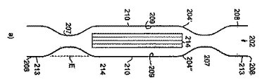
図1のa)〜d)では、第一の実施の形態においてバッテリー構造体101がどのように製造され得るかが示されている。図1のa)においてまず二つの成型部材104’,104”が認められる。当該成型部材は二つの電気化学セル102’,102”のジャケット103’,103”のジャケット部分を表している。この意味で図1のa)に示されている成型部材は、これら二つの異なる電気化学セル102’,102”に配設すべきものである。二つの成型部材は鏡面対称的であるが、その他の点では互いに同一に形成されている。この意味において成型部材の詳細については常に一度だけ説明する。成型部材はそれぞれ平面部分110を有しており、当該平面部分には径方向外側に向かって、継ぎ目部分107が周回するように接続している。平面部分110は平面Eを張設している。継ぎ目部分107は平面Eから突出している。
FIGS. 1a to 1d show how the
成型部材104’,104”は積層型成型部材として形成されている。このとき当該成型部材はアルミニウム層を有しており、当該アルミニウム層の両側には、ポリプロピレンから成る層が設けられている。ポリプロピレンはシール可能な材料である。シール可能な材料として、代替的にポリアミドが用いられ得る。
The
成型部材104の外面106にはそれぞれ、接合部分108が設けられており、当該接合部分は平面部分110内部にある。図1のb)に見られるように、二つの成型部材104’,104”は接合部分108において、第一の外周接着部115'によって互いに固定的に接合される。当該接着は、個々の成型部材104の接合部分108において、それぞれの接合面113で行われる。当該接合面113は平面E内にある。
Each of the outer surfaces 106 of the
図1のb)に示されている方法段階になると、異なる電気化学セルの成型部材104は互いに接合されているが、個々の電気化学セル102のジャケット103のさらなるジャケット部分は成型部材104’,104”に接続されていない。従ってジャケット103はまだ閉じられていない。次のステップにおいて、図1のc)に見られるように、成型部材104’,104”の内面109にはそれぞれ、電極スタック114が当接されている。続いてさらなる成型部材、すなわち104'''が104’に、もしくは、
104''''が104”に当接される。新たに当接された成型部材104''',104''''は同様に、さらなる電気化学セルのジャケットのさらなる成型部材と、すでに固定的に接合されている。
In the method step shown in FIG. 1b), the
104 ″ ″ is abutted against 104 ″. The newly abutted molded
図1のd)に見られるように、続いて電気化学セル102と当該電気化学セルのジャケット103にそれぞれ対応して設けられている成型部材104’,104'''もしくは104” ,104''''は、それぞれの継ぎ目部分107に設けられている第二の外周接着部115''によって互いに固定的に接合される。こうすると個々の電気化学セル102のジャケット103は閉鎖された状態になる。
As seen in FIG. 1 d),
図2は第一の実施の形態によるバッテリー構造体101の部分断面を詳細に示すものである。 図1のa)〜d)に加えて、全ての電気化学セル102において、電流導体111が認められる。当該電流導体は継ぎ目部分107の所定の箇所において、ジャケット103を介して延伸している。さらに、電流導体111は電極スタック114の少なくとも一部と電導的に接続されていることが認められる。
FIG. 2 shows a partial cross section of the
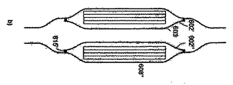
図3は図1に示すバッテリー構造体のさらなる構成を示すものである。その意味で、図1についての説明を参照すべきであり、図1に対する相違点のみを詳細に説明する。第二の実施の形態においてバッテリー構造体201がどのように製造され得るかが示されている。二つの成型部材204’,204”が認められる。当該成型部材は互いに対照的に形成されている。二つの成型部材204はそれぞれ、共通の電気化学セル202の共通のジャケット203のジャケット部分を表している。成型部材204は概ね図1に示す成型部材104と一致する。従って以下においては相違点のみを詳細に説明する。図1に示す成型部材104と異なり、成型部材204はそれぞれ二つの別個の接合部分208を有しており、当該接合部分は成型部材204の二つの異なる側において、継ぎ目部分207に対して外側に接続している。すなわち接合部分208は継ぎ目部分207の、平面部分210から離れた側に設けられている。このとき接合部分208は継ぎ目部分207から、平面Eに向かって突出している。このとき接合部分208は接合面213を有しており、当該接合面213は平面E内にある。その意味において、接合面213と成型部材204の平面部分210は互いに一直線になるように設けられている。
FIG. 3 shows a further configuration of the battery structure shown in FIG. In that sense, reference should be made to the description of FIG. 1, and only the differences from FIG. 1 will be described in detail. It is shown how the
成型部材のうちの一つ204’の内面209に電極スタック214が当接されることが認められる。続いて二つの成型部材のうちの他方204”が電極スタック214に当接されるとともに、他の成型部材204’に当接される。継ぎ目部分207において二つの成型部材204’,204”は、第一の接着部215'によって互いに固定的に接合される。これによって電気化学セル202のジャケット203は閉じられる。図3のc)に示されるさらなる方法のステップにおいて、二つの電気化学セル202',202''は図3のb)に示される方法のステップによって成立しているが、当該二つの電気化学セルは互いに当接され、第二の接着部215''によって接合部分208の個々の接合面213と互いに固定的に接合される。さらなる電気化学セルは同じ方法で、既存の電気化学セルと固定的に接合される。
It can be seen that the
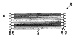
図4のa)および4b)において、バッテリー構造体201は個々の電気化学セル202を有して部分的に示されている。特に図4b)には、ハニカム構造が認められる。当該ハニカム構造は接合部分208と、電気化学セル202のジャケット203と、接着部215とから形成されている。
In FIGS. 4 a) and 4 b), the
図5は図1に示すバッテリー構造体のさらなる構成を示すものである。その意味で、図1についての説明を参照すべきであり、図1に対する相違点のみを詳細に説明する。図に示されている第三の実施の形態におけるバッテリー構造体301では、互いに接合された二つの成型部材304の代わりに、二つの電極スタック314の間に熱伝導プレート305が交互に設けられていることが認められる。このとき熱伝導プレート305はそれ自体で、電気化学セル302のジャケット303のジャケット部分を表している。継ぎ目部分307'において成型部材304は、第二の接着部315''によって熱伝導プレート305の継ぎ目部分307''と固定的に接合される。熱伝導プレート305はジャケット部分を表しており、当該ジャケット部分は二つの隣接する電気化学セル302を部分的に包囲するために用いられる。成型部材304は図1に示すバッテリー構造体の成型部材104と同一に形成されている。二つの隣接する成型部材304の接合は、図1に関してすでに説明された方法で行われる。電極スタックは成型部材304にも熱伝導プレート305にも当接している。
FIG. 5 shows a further configuration of the battery structure shown in FIG. In that sense, reference should be made to the description of FIG. 1, and only the differences from FIG. 1 will be described in detail. In the
図6では、第三の実施の形態におけるバッテリー構造体301であって、複数の電気化学セル302を含むバッテリー構造体が認められる。最も外側に示されている電気化学セル302の電流導体311は互いに接合されている。この意味で当該電気化学セルの電極スタック314は互いに直列に接続されている。当該構成は特に二成分系セルに適している。
In FIG. 6, a
図7は図1に示すバッテリー構造体のさらなる構成を示すものである。その意味で、図1についての説明を参照すべきであり、図1に対する相違点のみを詳細に説明する。第四の実施の形態におけるバッテリー構造体401は、複数の第一電気化学セル402'と、複数の第二電気化学セル402''を含んでおり、当該第一および第二電気化学セルは交互に並べて設けられている。 図7のa)では第二の電気化学セル402''が取り付けられる前の状態で示されている。当該第二の電気化学セル402''はセルスタック414を有しており、当該セルスタックは二つの同一の成型部材404の間に設けられている。成型部材404は平坦に形成されており、平面部分410は継ぎ目部分407とともに平面E内に設けられている。さらに第二外周フレーム412''が示されており、当該第二外周フレームはセルスタック414を包囲している。共通の第二電気化学セル402''に配設されている二つの成型部材404は、それぞれ第一の接着部415'によって当該二つの成型部材の個々の継ぎ目部分407において、第二フレーム412''と固定的に接合される。これによって第二電気化学セル402''のジャケット403は閉鎖される。
FIG. 7 shows a further structure of the battery structure shown in FIG. In that sense, reference should be made to the description of FIG. 1, and only the differences from FIG. 1 will be described in detail. The battery structure 401 according to the fourth embodiment includes a plurality of first
成型部材404が外周突出部418を有していることが認められる。当該外周突出部は第二フレーム412''を超えて径方向外側に突出している。これによって二つの成型部材404の間に径方向空隙部416が形成される。
It can be seen that the molded
二つの第二電気化学セル402''の間にさらなるセルスタック414が当接されており、当該さらなるセルスタックは第一フレーム412'に包囲される。第二フレーム412''はそれぞれ第二接着部415''によって、第二電気化学セル402''の成型部材404と、当該成型部材の接合部分408において固定的に接合される。第一フレーム412'は径方向延伸R1を有しており、当該径方向延伸は第二フレーム412''の径方向延伸R2よりも大きいことが認められる。その意味において第一フレーム412'は周方向において第二フレーム412''より突出しており、空隙部416の径方向領域内に延伸している。空隙部416内には器具419が介入できるが、当該器具は第二フレームと成型部材404との第二の接着部415''のために用いられる。
A
成型部材404はそれぞれ、第一電気化学セル402'のジャケットに対しても、第二電気化学セル402''のジャケットに対してもジャケット部分を形成する。第一フレーム412'は個々の第一電気化学セル402'のジャケット部分を形成する。第二フレーム412''は個々の第二電気化学セル402''のジャケット部分を形成する。
The molded
図8は図7に示すバッテリー構造体のさらなる構成を示すものである。その意味で、図7についての説明を参照すべきであり、図7に対する相違点のみを詳細に説明する。第五の実施の形態におけるバッテリー構造体501の電気化学セル502はそれぞれフレーム512を含んでおり、当該フレームは電極スタック514の周囲を包囲するように設けられている。個々の電気化学セル502はさらに、それぞれ二つの成型部材504を含んでおり、当該成型部材は概ね上記の実施の形態の成型部材404と同一に形成されている。フレーム512は個々の端面側に、外周段部517を有しており、当該外周段部にはそれぞれ成型部材504が当接され得、第一の接着部515'によって成型部材504と固定的に接合され得る。第二の接着部515''によって、個々の電気化学セル502のフレーム512はそれぞれ、フレーム512の端面側に設けられている接合部分508の接合面513において、互いに固定的に接合される。
FIG. 8 shows a further configuration of the battery structure shown in FIG. In that sense, reference should be made to the description of FIG. 7, and only the differences from FIG. 7 will be described in detail. The
図9は図1に示すバッテリー構造体のさらなる構成を示すものである。その意味で、図1についての説明を参照すべきであり、図1に対する相違点のみを詳細に説明する。第六の実施の形態におけるバッテリー構造体601は、複数の電気化学セル602を含んでおり、当該電気化学セルのジャケット603はそれぞれ二つの成型部材604’,604”によって形成され、当該成型部材は同一または互いに鏡面対照的に形成されていない。第一成型部材604’は図1に示す成型部材104と同一に形成されている。第二成型部材604''は基本構造において、図3に示す第一成型部材204’ と同一に形成されている。第一成型部材604’は当該第一成型部材の継ぎ目部分607'において第一の接着部615'によって第二成型部材604''の継ぎ目部分607''と固定的に接合されている。これによって電気化学セル602と当該電気化学セルのジャケット603は閉鎖される。接合部分608'は図3に示す第一成型部材204’ とは異なり、平面Eから離れる方向に、継ぎ目部分607''から突出する。このとき第二成型部材604''は、二つの成型部材が接合された状態で、径方向において第一成型部材604’を超えて突出している。第二成型部材604''はさらなる製造ステップにおいて、隣接する電気化学セル602のさらなる第二成型部材604''に当接され、第二の接着部615''によって当該さらなる第二成型部材と、それぞれ接合部分608の内面609において固定的に接合される。第二成型部材604''はさらに第三の接着部615'''によって、さらなる電気化学セルのさらなる第二成型部材604''と固定的に接合される。第三の接着部615'''はさらなる接合部分608''において、図1に示す第一の実施の形態による第一の接着部115'と同一に実現される。この意味で、これに関連する説明を参照すべきである。第二成型部材604''はこの意味で二つの接合部分608',608''であって、当該二つの接合部分において、第二成型部材604''が他の電気化学セルの成型部材と接合されている二つの接合部分を有している。
FIG. 9 shows a further structure of the battery structure shown in FIG. In that sense, reference should be made to the description of FIG. 1, and only the differences from FIG. 1 will be described in detail. The
電気化学セル602のジャケット603を気密かつ液密に封止する第一の接着部615'が漏れやすくなった場合、第二の接着部615''によって環境と電気化学セル602の内部との物質交換が回避される。電気化学セル602はこの点で冗長性を有するがゆえに、より優れたジャケット603を有している。
When the first
実施の形態に関して説明された全ての接着部に当てはまるのは、ジャケット部分同士の接着部が、ジャケット部分のヒートシール可能な層によって形成されているということである。このとき当該材料接続的な接合を作り出すために、ジャケット部分のヒートシール可能な層は互いに当接され、続いて熱が供給される。熱の供給により、ジャケット部分においてヒートシール可能な材料は溶融し、従って、それぞれ他のジャケット部分のヒートシール可能な材料と材料接続的に接合される。付加的な接着剤またはシーリング剤、すなわち材料接続的な接合を作り出すための補助的材料であって、ジャケット部分の層の構成部材ではない補助的材料は設けられていない。 What applies to all the adhesive portions described with respect to the embodiment is that the adhesive portions of the jacket portions are formed by a heat-sealable layer of the jacket portions. At this time, the heat-sealable layers of the jacket portion are brought into contact with each other and subsequently supplied with heat in order to create the material-connected bond. Due to the supply of heat, the heat-sealable material in the jacket part melts and is thus joined in material connection with the heat-sealable material in each other jacket part. There are no additional adhesives or sealants, i.e. auxiliary materials for creating a material-connected bond, which are not components of the layer of the jacket part.
101,201,301,401,501,601 バッテリー構造体
102,202,302,402,502,602 電気化学セル
103,203,303,403,503,603 ジャケット
104,204,304,404,504,604 成型部材
305 熱伝導プレート
106,206,306,406,506,606 外面
107,207,307,407,507,607 継ぎ目部分
108,208,308,408,508,608 接合部分
109,209,309,409,509,609 内面
110,210,310,410,510,610 平面部分
111,211,311,411,511,611 電流導体
412,512 フレーム
113,213,313,413,513,613 接合面
114,214,314,414,514,614 電極スタック
115,215,315,415,515,615 接着部
416 空隙部
517 段部
418 突出部
419 器具
E 平面
R 径方向延伸
101, 201, 301, 401, 501, 601
R radial stretching
Claims (34)
前記第一の電気化学セル(102,202,…)の前記ジャケット(103,203,…)のジャケット部分(104,204,…)は、前記第二の電気化学セル(102,202,…)の前記ジャケット(103,203,…)のジャケット部分(104,204,…)と材料接続的に接合されることを特徴とする方法。 A battery structure (101, 201, ...) including at least one first electrochemical cell (102, 202, ...) and at least one second electrochemical cell (102, 202, ...) is manufactured. In which each electrochemical cell has a jacket (103, 203, ...),
The jacket portion (104, 204, ...) of the jacket (103, 203, ...) of the first electrochemical cell (102, 202, ...) is the second electrochemical cell (102, 202, ...). In which the jacket portions (104, 204, ...) of the jackets (103, 203, ...) are joined in material connection.
当該ジャケット(103,203,…)は、平面部分(110,210,…)と継ぎ目部分(107,207,…)とを有する少なくとも一つの成型部材(104,204,…)を含んでおり、
当該継ぎ目部分(107,207,…)は前記平面部分(110,210,…)の周囲に設けられている電気化学セルにおいて、
前記成型部材(104,204,…)に接合部分(108,208,…)が設けられていることを特徴とする電気化学セル。 An electrochemical cell (102, 202, ...) comprising at least one electrode stack (109, 209, ...) at least partially surrounded by a jacket (103, 203, ...),
The jacket (103, 203,...) Includes at least one molded member (104, 204,...) Having a plane portion (110, 210,...) And a seam portion (107, 207,...).
In the electrochemical cell provided around the planar portion (110, 210,...), The joint portion (107, 207,...)
An electrochemical cell characterized in that a joining portion (108, 208, ...) is provided on the molding member (104, 204, ...).
Applications Claiming Priority (3)
| Application Number | Priority Date | Filing Date | Title |
|---|---|---|---|
| DE102009031014.2 | 2009-06-29 | ||
| DE102009031014A DE102009031014A1 (en) | 2009-06-29 | 2009-06-29 | Method of making a battery assembly |
| PCT/EP2010/003318 WO2011000454A1 (en) | 2009-06-29 | 2010-06-01 | Method for producing a battery arrangement |
Publications (2)
| Publication Number | Publication Date |
|---|---|
| JP2012531717A true JP2012531717A (en) | 2012-12-10 |
| JP2012531717A5 JP2012531717A5 (en) | 2013-07-18 |
Family
ID=42562937
Family Applications (1)
| Application Number | Title | Priority Date | Filing Date |
|---|---|---|---|
| JP2012518028A Pending JP2012531717A (en) | 2009-06-29 | 2010-06-01 | Battery structure manufacturing method |
Country Status (8)
| Country | Link |
|---|---|
| US (1) | US20120156538A1 (en) |
| EP (1) | EP2449611A1 (en) |
| JP (1) | JP2012531717A (en) |
| KR (1) | KR20120093757A (en) |
| CN (1) | CN102484222A (en) |
| BR (1) | BRPI1014947A2 (en) |
| DE (1) | DE102009031014A1 (en) |
| WO (1) | WO2011000454A1 (en) |
Families Citing this family (4)
| Publication number | Priority date | Publication date | Assignee | Title |
|---|---|---|---|---|
| DE102012018158A1 (en) * | 2012-09-14 | 2014-04-10 | Eads Deutschland Gmbh | Structural component e.g. aircraft component for aircraft, has integrated energy storage element which stores electrical energy |
| KR101609212B1 (en) | 2013-08-28 | 2016-04-05 | 주식회사 엘지화학 | Battery Module Having Structure for Prevention of Coolant and Venting Gas Mixing |
| US11764443B2 (en) | 2018-06-27 | 2023-09-19 | Kyocera Corporation | Electrochemical cell |
| CN113097610B (en) * | 2021-03-31 | 2023-02-24 | 东莞新能安科技有限公司 | Electrochemical device module and electronic device |
Citations (4)
| Publication number | Priority date | Publication date | Assignee | Title |
|---|---|---|---|---|
| JP2000200593A (en) * | 1999-01-04 | 2000-07-18 | Mitsubishi Electric Corp | Battery pack |
| JP2004055441A (en) * | 2002-07-23 | 2004-02-19 | Nissan Motor Co Ltd | Laminated film sheathed battery, battery group, battery pack, and battery pack module |
| JP2006172994A (en) * | 2004-12-17 | 2006-06-29 | Nissan Motor Co Ltd | Battery pack and manufacturing method of battery pack |
| JP2009026735A (en) * | 2007-07-19 | 2009-02-05 | Samsung Sdi Co Ltd | Pouch battery pack |
Family Cites Families (6)
| Publication number | Priority date | Publication date | Assignee | Title |
|---|---|---|---|---|
| NL7405433A (en) * | 1973-05-10 | 1974-11-12 | ||
| FR2275894A1 (en) * | 1974-06-20 | 1976-01-16 | Accumulateurs Fixes | Accumulator bank interconnection - connections made through cell walls, connector acting also as wall seal and cell clamp |
| JP4088359B2 (en) * | 1997-10-20 | 2008-05-21 | 松下電器産業株式会社 | Collective sealed secondary battery |
| US6444353B1 (en) * | 1999-03-03 | 2002-09-03 | Matsushita Electric Industrial Co., Ltd. | Integrated sealed secondary battery |
| JP4211322B2 (en) | 2002-08-26 | 2009-01-21 | 日産自動車株式会社 | Multilayer battery, battery pack, battery module and electric vehicle |
| CN100361326C (en) * | 2004-03-23 | 2008-01-09 | 日本电气株式会社 | Film-packaged electric device and its manufacturing method |
-
2009
- 2009-06-29 DE DE102009031014A patent/DE102009031014A1/en not_active Withdrawn
-
2010
- 2010-06-01 EP EP10722636A patent/EP2449611A1/en not_active Withdrawn
- 2010-06-01 KR KR1020117031487A patent/KR20120093757A/en not_active Application Discontinuation
- 2010-06-01 JP JP2012518028A patent/JP2012531717A/en active Pending
- 2010-06-01 US US13/379,948 patent/US20120156538A1/en not_active Abandoned
- 2010-06-01 BR BRPI1014947A patent/BRPI1014947A2/en not_active IP Right Cessation
- 2010-06-01 WO PCT/EP2010/003318 patent/WO2011000454A1/en active Application Filing
- 2010-06-01 CN CN201080029440XA patent/CN102484222A/en active Pending
Patent Citations (4)
| Publication number | Priority date | Publication date | Assignee | Title |
|---|---|---|---|---|
| JP2000200593A (en) * | 1999-01-04 | 2000-07-18 | Mitsubishi Electric Corp | Battery pack |
| JP2004055441A (en) * | 2002-07-23 | 2004-02-19 | Nissan Motor Co Ltd | Laminated film sheathed battery, battery group, battery pack, and battery pack module |
| JP2006172994A (en) * | 2004-12-17 | 2006-06-29 | Nissan Motor Co Ltd | Battery pack and manufacturing method of battery pack |
| JP2009026735A (en) * | 2007-07-19 | 2009-02-05 | Samsung Sdi Co Ltd | Pouch battery pack |
Also Published As
| Publication number | Publication date |
|---|---|
| DE102009031014A1 (en) | 2010-12-30 |
| BRPI1014947A2 (en) | 2016-04-26 |
| CN102484222A (en) | 2012-05-30 |
| EP2449611A1 (en) | 2012-05-09 |
| KR20120093757A (en) | 2012-08-23 |
| WO2011000454A1 (en) | 2011-01-06 |
| US20120156538A1 (en) | 2012-06-21 |
Similar Documents
| Publication | Publication Date | Title |
|---|---|---|
| JP6101823B2 (en) | Battery module having new structure and battery pack including the same | |
| JP6053227B2 (en) | Battery assembly having a single electrode terminal coupling part | |
| KR101216422B1 (en) | Secondary Battery Having Sealing Portion of Improved Insulating Property | |
| JP4728758B2 (en) | Electric device module manufacturing method and electric device module | |
| JP5374979B2 (en) | Batteries and batteries | |
| JP6743664B2 (en) | Power storage device and method of manufacturing power storage device | |
| JP2007073510A (en) | Secondary battery and battery module including same | |
| JP6334725B2 (en) | Battery module including voltage sensing member having receptacle structure | |
| KR101170881B1 (en) | High Power Secondary Battery of Series Connection Structure | |
| JP2013546129A (en) | Electrode stack structure of electrochemical energy storage device | |
| JP5879550B2 (en) | Thin secondary battery | |
| WO2014010419A1 (en) | Battery assembly | |
| JP2012531717A (en) | Battery structure manufacturing method | |
| KR101115382B1 (en) | High Power Secondary Battery of Series Connection Structure | |
| JP4887650B2 (en) | Single cells and batteries | |
| JP5493265B2 (en) | Batteries, battery packs and vehicles equipped with the same | |
| WO2013168260A1 (en) | Secondary battery | |
| JP2007095599A (en) | Thin battery module | |
| JP5682371B2 (en) | Electric storage device, method for manufacturing electric storage cell, and method for manufacturing electric storage device | |
| JP2006172911A (en) | Battery module and its manufacturing method | |
| JP2010211944A (en) | Power storage device and power storage module | |
| JP2018110084A (en) | Power storage device and method of manufacturing power storage device | |
| JP5895488B2 (en) | Positioning member and mold | |
| JP2006164863A (en) | Flat battery pack and method for manufacturing it | |
| WO2013018552A1 (en) | Battery |
Legal Events
| Date | Code | Title | Description |
|---|---|---|---|
| A521 | Request for written amendment filed |
Free format text: JAPANESE INTERMEDIATE CODE: A523 Effective date: 20130603 |
|
| A621 | Written request for application examination |
Free format text: JAPANESE INTERMEDIATE CODE: A621 Effective date: 20130603 |
|
| A977 | Report on retrieval |
Free format text: JAPANESE INTERMEDIATE CODE: A971007 Effective date: 20140513 |
|
| A131 | Notification of reasons for refusal |
Free format text: JAPANESE INTERMEDIATE CODE: A131 Effective date: 20140617 |
|
| A02 | Decision of refusal |
Free format text: JAPANESE INTERMEDIATE CODE: A02 Effective date: 20141118 |