JP2012531359A - Wheel made of polymer material - Google Patents
Wheel made of polymer material Download PDFInfo
- Publication number
- JP2012531359A JP2012531359A JP2012518699A JP2012518699A JP2012531359A JP 2012531359 A JP2012531359 A JP 2012531359A JP 2012518699 A JP2012518699 A JP 2012518699A JP 2012518699 A JP2012518699 A JP 2012518699A JP 2012531359 A JP2012531359 A JP 2012531359A
- Authority
- JP
- Japan
- Prior art keywords
- wheel
- insert
- hole
- wheel according
- central
- Prior art date
- Legal status (The legal status is an assumption and is not a legal conclusion. Google has not performed a legal analysis and makes no representation as to the accuracy of the status listed.)
- Pending
Links
Images


Classifications
-
- B—PERFORMING OPERATIONS; TRANSPORTING
- B60—VEHICLES IN GENERAL
- B60B—VEHICLE WHEELS; CASTORS; AXLES FOR WHEELS OR CASTORS; INCREASING WHEEL ADHESION
- B60B5/00—Wheels, spokes, disc bodies, rims, hubs, wholly or predominantly made of non-metallic material
- B60B5/02—Wheels, spokes, disc bodies, rims, hubs, wholly or predominantly made of non-metallic material made of synthetic material
-
- B—PERFORMING OPERATIONS; TRANSPORTING
- B29—WORKING OF PLASTICS; WORKING OF SUBSTANCES IN A PLASTIC STATE IN GENERAL
- B29C—SHAPING OR JOINING OF PLASTICS; SHAPING OF MATERIAL IN A PLASTIC STATE, NOT OTHERWISE PROVIDED FOR; AFTER-TREATMENT OF THE SHAPED PRODUCTS, e.g. REPAIRING
- B29C45/00—Injection moulding, i.e. forcing the required volume of moulding material through a nozzle into a closed mould; Apparatus therefor
- B29C45/0005—Injection moulding, i.e. forcing the required volume of moulding material through a nozzle into a closed mould; Apparatus therefor using fibre reinforcements
-
- B—PERFORMING OPERATIONS; TRANSPORTING
- B60—VEHICLES IN GENERAL
- B60B—VEHICLE WHEELS; CASTORS; AXLES FOR WHEELS OR CASTORS; INCREASING WHEEL ADHESION
- B60B1/00—Spoked wheels; Spokes thereof
- B60B1/02—Wheels with wire or other tension spokes
- B60B1/04—Attaching spokes to rim or hub
- B60B1/043—Attaching spokes to rim
- B60B1/044—Attaching spokes to rim by the use of spoke nipples
- B60B1/045—Attaching spokes to rim by the use of spoke nipples characterised by their specific shape
-
- B—PERFORMING OPERATIONS; TRANSPORTING
- B29—WORKING OF PLASTICS; WORKING OF SUBSTANCES IN A PLASTIC STATE IN GENERAL
- B29K—INDEXING SCHEME ASSOCIATED WITH SUBCLASSES B29B, B29C OR B29D, RELATING TO MOULDING MATERIALS OR TO MATERIALS FOR MOULDS, REINFORCEMENTS, FILLERS OR PREFORMED PARTS, e.g. INSERTS
- B29K2077/00—Use of PA, i.e. polyamides, e.g. polyesteramides or derivatives thereof, as moulding material
-
- B—PERFORMING OPERATIONS; TRANSPORTING
- B29—WORKING OF PLASTICS; WORKING OF SUBSTANCES IN A PLASTIC STATE IN GENERAL
- B29K—INDEXING SCHEME ASSOCIATED WITH SUBCLASSES B29B, B29C OR B29D, RELATING TO MOULDING MATERIALS OR TO MATERIALS FOR MOULDS, REINFORCEMENTS, FILLERS OR PREFORMED PARTS, e.g. INSERTS
- B29K2105/00—Condition, form or state of moulded material or of the material to be shaped
- B29K2105/06—Condition, form or state of moulded material or of the material to be shaped containing reinforcements, fillers or inserts
- B29K2105/08—Condition, form or state of moulded material or of the material to be shaped containing reinforcements, fillers or inserts of continuous length, e.g. cords, rovings, mats, fabrics, strands or yarns
-
- B—PERFORMING OPERATIONS; TRANSPORTING
- B29—WORKING OF PLASTICS; WORKING OF SUBSTANCES IN A PLASTIC STATE IN GENERAL
- B29L—INDEXING SCHEME ASSOCIATED WITH SUBCLASS B29C, RELATING TO PARTICULAR ARTICLES
- B29L2031/00—Other particular articles
- B29L2031/32—Wheels, pinions, pulleys, castors or rollers, Rims
- B29L2031/322—Wheels, pinions, pulleys, castors or rollers, Rims made wholly of plastics
Landscapes
- Engineering & Computer Science (AREA)
- Mechanical Engineering (AREA)
- Chemical & Material Sciences (AREA)
- Materials Engineering (AREA)
- Manufacturing & Machinery (AREA)
- Injection Moulding Of Plastics Or The Like (AREA)
- Tires In General (AREA)
- Compositions Of Macromolecular Compounds (AREA)
- Body Structure For Vehicles (AREA)
- Reinforced Plastic Materials (AREA)
Abstract
本発明のホイールは、車両のシャフトの端部に取り付けられる中央の穴(11)および固定ボルトを通すための複数の偏心した穴(12)が設けられた中央のディスク(10)と、車両のタイヤを保持するように構成された外周のリング(20)とによって形成される本体(C)を備えており、前記ホイールの本体(C)は、40%〜70%の熱可塑性ポリマーマトリクスと、30%〜60%の合成繊維と、0.01%〜10%の添加剤とを均質混合にて含むポリマー複合材料で、単一部品にて射出成型される。 The wheel of the present invention comprises a central disc (10) provided with a central hole (11) attached to the end of a vehicle shaft and a plurality of eccentric holes (12) for passing fixing bolts, A body (C) formed by an outer ring (20) configured to hold a tire, the wheel body (C) comprising 40% to 70% thermoplastic polymer matrix; A polymer composite material containing 30% to 60% synthetic fiber and 0.01% to 10% additive in intimate mixing and injection molded in a single part.
Description
本発明は、自動車、小型および大型多目的車両、オートバイ、三輪車、四輪車、荷物および人々の域内移動のための車両、農業用車両、ならびに他の用途のための車両など、種々の車両に装着される熱可塑性複合材料で作られたタイヤホイールの新規な構造に関する。 The present invention is mounted on a variety of vehicles, including automobiles, small and large multipurpose vehicles, motorcycles, tricycles, quadricycles, vehicles for luggage and people movement, agricultural vehicles, and vehicles for other uses. Relates to a novel structure of a tire wheel made of a thermoplastic composite material.
先行技術から知られているとおり、ポリマー複合材料は、2つ以上の材料が特性の相乗効果および性能の最適化を達成するように組み合わせられ、すなわち単一の材料の特性よりも優れた特性を得るように組み合わせられた材料である。複合材料は、通常は、ポリマーベースを1つ以上の補強材料と組み合わせることによってもたらされる。 As is known from the prior art, polymer composites are combined so that two or more materials achieve property synergies and performance optimization, i.e., properties superior to those of a single material. Material combined to obtain. Composite materials are usually provided by combining a polymer base with one or more reinforcing materials.
産業において、重量の削減を特性の改善、性能の最適化、および設計の自由度によってもたらされる差別化された視覚的外観とともにもたらす製品について、顕著な需要が存在する。これらの特徴の他に、生産性の向上、品質の改善、リサイクル性ゆえの環境保護上の魅力、快適性、安全性、自律性の改善、汚染物質の排出削減、などが期待される。 There is significant demand in the industry for products that bring weight reduction with differentiated visual appearance brought about by improved properties, performance optimization, and design freedom. In addition to these features, it is expected to improve productivity, improve quality, attract environmental protection due to recyclability, improve comfort, safety, autonomy, reduce pollutant emissions, and so on.
軽量合金ホイールは、鋳造による単一の部品にて製造され、鋼製ホイールは、プレスによるリムおよびディスクから製作され、溶接スポットを必要とし、溶接スポットにおいて酸化点が生じ、製品の耐久性および安全性が損なわれる可能性がある。他に考慮すべき側面は、金属材料がポリマー材料よりも高い比重を有するという事実であり、そのような材料で製造されるホイールの質量は、必然的に大きくなり、したがって車両が重くなり、エネルギーおよび/または燃料の消費が多くなる。 Lightweight alloy wheels are manufactured in a single piece by casting, steel wheels are made from press rims and discs, require welding spots, create oxidation points at the welding spots, product durability and safety May be impaired. Another aspect to consider is the fact that metallic materials have a higher specific gravity than polymer materials, and the mass of wheels made of such materials will inevitably be large, thus making vehicles heavy and energy And / or fuel consumption increases.
上述の不都合の他に、これらの知られているホイールは、衝撃の場合に恒久的な変形(塑性変形)を有し、製品および製品に組み合わせられたシステムに深刻な損傷や、あるいは恒久的な損傷さえ引き起こす可能性がある。具体的には、軽量合金ホイールの鋳造プロセスにおいて、抑制が困難であって製造プロセスに本質的につきまとう材料中の気孔の存在に起因して、不具合の可能性が高くなる。その後の機械加工の工程が、大量の油残留物および金属くずを生じさせる高コストかつ時間のかかるプロセスである。さらに、ホイールの製造サイクルの全体を分析すると、電気エネルギー、水、および鋳造プロセスにつきものの他の投入物が、大量に消費されている。 In addition to the disadvantages mentioned above, these known wheels have a permanent deformation (plastic deformation) in the event of an impact, causing serious damage to the product and the system associated with the product, or permanent. It can even cause damage. Specifically, in the lightweight alloy wheel casting process, there is an increased likelihood of failure due to the presence of pores in the material that are difficult to suppress and inherent in the manufacturing process. Subsequent machining steps are costly and time consuming processes that produce large amounts of oil residue and scrap metal. Furthermore, analysis of the entire wheel manufacturing cycle consumes large amounts of electrical energy, water, and other inputs associated with the casting process.
ホイールを、いくつかのプロセスにて、多くの場合に熱硬化性材料(リサイクルできない)を使用して、ガラス繊維で補強されたポリマーで製造することが試みられているが、それらの試みは検証試験において不合格となり、あるいは商業的に実現不可能であると考えられている。 Attempts have been made to manufacture wheels with polymers reinforced with glass fibers, often using thermoset materials (which cannot be recycled), in some processes, but these attempts have been verified. It is considered that the test has failed or is not commercially feasible.
放熱の目的のためにディスクを固定ボルトとブレーキシステムとの間に挿入して使用している先行技術の例が、米国特許第4,900,097号明細書に記載されている。この構造においては、ディスクがプラスチック製のリムから分離する可能性がある。 An example of prior art using a disk inserted between a fixing bolt and a brake system for heat dissipation purposes is described in US Pat. No. 4,900,097. In this structure, the disc may be separated from the plastic rim.
米国特許第3,811,737号明細書が、ボルトが耐圧縮性に乏しい樹脂へと過度に締め込まれることがないようにするために、金属板を使用することを提案している。 U.S. Pat. No. 3,811,737 proposes the use of a metal plate to prevent the bolt from being over-tightened into a resin with poor compression resistance.
米国特許第3,917,352号明細書が、プラスチック構造を補強するためのいくつかの連続的なガラス繊維フィラメントを提示しているが、製造プロセスが高価かつ複雑であり、最終的な製品が経済的に実現不可能または競争力に乏しいものになっている。 US Pat. No. 3,917,352 presents several continuous glass fiber filaments to reinforce plastic structures, but the manufacturing process is expensive and complex, and the final product is It is not economically feasible or competitive.
米国特許第4,072,358号明細書においては、ホイールが、ポリアミド(PI)シートを切断ガラス繊維と一緒に圧縮するプロセスにて成型されている。 In U.S. Pat. No. 4,072,358, the wheels are molded in a process where a polyamide (PI) sheet is compressed together with cut glass fibers.
米国特許第5,826,948号明細書が、互いに貼り合わせられる2つの部品にて製造されたホイールを提示しているが、2つの射出成型金型が必要であり、製造コストが高くなる。 U.S. Pat. No. 5,826,948 presents a wheel manufactured with two parts that are bonded together, but requires two injection molds and increases manufacturing costs.
米国特許第5,268,139号明細書が、より弱い領域において異なるポリマー流動線からなるニットライン(knit line)を回避する設計を開示しているが、これはホイールの設計の自由度ならびにホイールのプラスチックフォームの各々の設計要件への適合にとって、大きな制約である。 U.S. Pat. No. 5,268,139 discloses a design that avoids knit lines consisting of different polymer flow lines in the weaker regions, but this gives freedom in wheel design as well as wheel design. This is a great constraint for meeting the design requirements of each plastic foam.
プラスチック材料にて形成される知られている車両用ホイールは、一般にポリマー材料から得られるが、その組成が、構造的な耐力、耐候性、経年劣化、ならびにホイールの取り付けられるシャフト端部における大きな締め付け力および保持力への耐性に関し、さらには製造ならびに各々の用途における美的および機能的要件への構造設計の適合に関して、欠点を抱えている。 Known vehicle wheels formed of plastic materials are generally derived from polymer materials, but their composition is structural strength, weather resistance, aging, and large tightening at the end of the shaft to which the wheels are attached. There are drawbacks with respect to resistance to force and holding force, as well as adaptation of the structural design to manufacturing and aesthetic and functional requirements in each application.
これまでに知られている車両の空気入りタイヤのホイールが抱える欠点に鑑み、本発明の目的は、ポリマー材料によるホイールであって、比較的簡単に製造でき、高い設計の柔軟性を有し、さらには引張、圧縮、曲げ、および衝撃に対して高い耐性を有し、たとえ車両における使用時に気候条件および化学的攻撃に曝されても長い寿命を約束するホイールを提供することにある。 In view of the drawbacks of known pneumatic tire wheels of vehicles, the object of the present invention is a wheel made of polymer material, which can be manufactured relatively easily, has high design flexibility, Furthermore, it is to provide a wheel that is highly resistant to tension, compression, bending and impact, and that promises a long life even when exposed to climatic conditions and chemical attack when used in vehicles.
これらの肯定的な特性が、車両のシャフトの端部に取り付けられる中央の穴および固定ボルトを通すための複数の偏心した穴が設けられた中央のディスクと、車両のタイヤを保持するように構成された外周のリングとによって形成される本体を備える形式の本明細書において提案されるホイールにおいて得られる。本明細書において考慮されるホイールは、40%〜70%の熱可塑性ポリマーマトリクス(好ましくは、ポリアミド(PA))と、30%〜60%の合成繊維と、0.01%〜10%の添加剤とを均質混合にて含む新規なポリマー複合材料から、単一部品にて射出成型される。 These positive characteristics are configured to hold the vehicle's tires and a central disc with a plurality of eccentric holes through which a central hole and fixing bolts are attached to the end of the vehicle's shaft Obtained in a wheel proposed herein in the form of a body comprising a body formed by a peripheral ring that is made up. The wheels considered herein consist of 40% to 70% thermoplastic polymer matrix (preferably polyamide (PA)), 30% to 60% synthetic fibers, and 0.01% to 10% addition. From a new polymer composite containing the agent in intimate mixing, it is injection molded in a single part.
この新規なホイールの構造的および機能的な特徴に加えて、射出成型によるホイール本体の製造が、製造サイクルの短縮を可能にし、コストを削減し、製品を経済的に実現可能にすることを、理解すべきである。 In addition to the structural and functional features of this new wheel, the manufacture of the wheel body by injection molding enables a shortened manufacturing cycle, reduces costs and makes the product economically feasible, Should be understood.
製品の開発は、美学(意匠)および機能の両方の点において、製品の性能の分析を加速して試行錯誤を回避する有限要素解析(FEA)のためのソフトウェアを使用することによる構造解析、疲労、および組織などのコンピュータシミュレーション、設計/製品/材料/プロセスおよびツーリングの間の相互作用分析、ならびに物理的なベンチテストのシミュレーションと連携する。 Product development includes structural analysis, fatigue using software for finite element analysis (FEA) that accelerates product performance analysis and avoids trial and error in both aesthetic (design) and function And computer simulations such as organization, interaction analysis between design / product / material / process and tooling, and physical bench test simulation.
そのようなシミュレーションは、製品の構想、開発、および検証の工程に要する時間およびコストを減らす。最後に、試験室および疲労試験が、耐久性および実地試験との組み合わせにおいて、個々の用途の要件を満たす製品の承認を可能にする。しかしながら、ポリマー複合材料によるこの種の製品については、特定の国内および国際規則および規制が存在しないため、性能の評価を、金属材料およびそれらの合金で一般的に製造される現在の製品に適用されるSAE、ISO、およびNBR(ブラジル規則)の仕様および規制にもとづいて行った。 Such simulation reduces the time and cost required for the product conception, development and verification processes. Finally, laboratory and fatigue tests allow the approval of products that meet individual application requirements in combination with durability and field tests. However, because there are no specific national and international rules and regulations for this type of product with polymer composites, the performance assessment applies to current products that are generally made of metallic materials and their alloys. SAE, ISO, and NBR (Brazil Rules) specifications and regulations.
他の重要な点は、本発明のホイールを受け入れるために、車両を変更する必要がない点にある。 Another important point is that the vehicle does not need to be modified to accept the wheel of the present invention.
本発明を、本発明のホイールについて考えられる実施形態の例示として提示される添付の図面を参照して後述する。 The present invention will be described below with reference to the accompanying drawings presented as examples of possible embodiments for the wheel of the present invention.
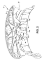
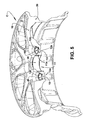
すでに述べ、さらには添付の図面にも示されているとおり、本発明のホイールは、車両のシャフトの端部に取り付けられる中央の穴11および固定ボルトを通すための複数の偏心した穴12が設けられた中央のディスク10と、車両のタイヤを保持するように構成された外周のリング20とによって形成される本体Cを備える形式である。図示の構造的形状においては、中央の穴11が、おおむね円柱形かつ軸方向の最も内側に位置する取り付け部11aを有しており、この取り付け部11aが、車両のそれぞれのシャフトの端部の周囲に取り付けられる。他方で、偏心した穴12は、ホイールを車両へと取り付けるボルトの本体のためのガイドとして機能する軸方向の最も内側の円柱形部分12aと、車両の固定ボルトまたはナットに作用可能に組み合わせられる六角ボルトまたはナットの円錐形の領域を内部に収容する軸方向の最も外側の円錐台形状の部分12bとを有している。
As already mentioned and also shown in the accompanying drawings, the wheel of the present invention is provided with a
本発明によれば、本体Cが、40%〜70%の熱可塑性ポリマーマトリクスと、30%〜60%の合成繊維と、0.01%〜10%の添加剤とを均質混合にて含むポリマー複合材料で、単一部品にて射出成型される。 According to the present invention, the body C comprises a 40% to 70% thermoplastic polymer matrix, 30% to 60% synthetic fiber, and 0.01% to 10% additive in a homogeneous mixture. A composite material that is injection molded in a single part.
好ましくは、ポリマーマトリクスがポリアミド(PA)にて得られ、合成繊維が、引張、曲げ、および衝撃に対して高い耐性を有する長いガラス繊維の細くて柔軟なフィラメントによって定められている。 Preferably, the polymer matrix is obtained from polyamide (PA) and the synthetic fibers are defined by long, thin, flexible filaments of glass fibers that are highly resistant to tension, bending and impact.
さらに、ホイールの本体Cを形成するための好ましい添加剤は、相溶化剤、経年劣化抑制剤、熱安定剤、UV添加剤/吸収剤、難燃剤、加工助剤、一次および二次酸化抑制剤、ならびに顔料によって定められる。 Further preferred additives for forming the wheel body C are compatibilizers, aging inhibitors, heat stabilizers, UV additives / absorbers, flame retardants, processing aids, primary and secondary oxidation inhibitors. As well as the pigment.
車両における耐用年数においてホイールへと加わる力に応じ、車両のシャフトの端部またはホイールを車両へと固定するためのボルトに直接接触する本体Cの部位に、より高い構造的耐性を付与するために、金属合金で作られ、中央の穴11または偏心した穴12のみあるいは中央の穴11および偏心した穴12の両方の内部に配置されるインサート30、40の形状をとる補強要素を設けることが、好都合であるかもしれず、さらには必要であるかもしれない。
In order to give higher structural resistance to the end of the shaft of the vehicle or the part of the body C that directly contacts the bolt for fixing the wheel to the vehicle, depending on the force applied to the wheel during the service life of the vehicle Providing a reinforcing element made of a metal alloy and taking the form of
図1に示した構造においては、本体Cからインサート30、40が除かれている。
In the structure shown in FIG. 1, the
図2に示した構造においては、中央の穴11の取り付け部11aだけが、該当のインサート30によって内側から覆われている。このインサート30が、中央の穴11の前記取り付け部11aの軸方向の延在の全体にわたって延びても、あるいは前記延在のうちの一部だけを延びてもよいことを、理解すべきである。
In the structure shown in FIG. 2, only the
図3の構造においては、偏心した穴12だけが、それぞれの筒状のインサート40によって内側から覆われている。この図においては、偏心した穴12の各々の円柱形部分12aおよび円錐台形状の部分12bの両方が、前記偏心した穴の各部分の形状に従った形を有する該当のインサート40によって内側から完全に覆われている。
In the structure of FIG. 3, only the
図4は、図3の構造上の変形例を示しており、この変形例においては、金属インサート40が、偏心した穴12のそれぞれの円錐台形状の部分12bの全体を内側から覆っているが、前記偏心した穴の円柱形部分12aの隣接する領域だけを覆っている。
FIG. 4 shows a structural variation of FIG. 3, in which the
図5は、中央の穴11がその取り付け部11aの軸方向の延在の全体がインサート30によって覆われている一方で、偏心した穴12については、図4に示されるように軸方向の延在のうちの一部分だけがそれぞれのインサート40によって覆われている構造を示している。
FIG. 5 shows that the
図6は、図5の解決策に定められる態様を包含するが、偏心した穴12のすべてのインサート40が中央の穴11の取り付け部11aを覆うインサート30に結合して単一部品となっている構造を示している。図5および図6の構造が、それぞれの偏心した穴12の軸方向の延在の全体を占める筒状のインサート40の使用も想定できることを、理解すべきである。
FIG. 6 includes the embodiment defined in the solution of FIG. 5, but all the
金属インサート30、40は、適用される場合には、これらの部材を巻き込んでこれらの部材の位置決めおよび機械的な固定を保証する複合材料の注入に先立って金型内に配置して射出成型されるか、あるいは射出成型プロセスの後で、挿入の力および変位が監視される適切な装置による干渉によって取り付けられる。機械的な固定は、穴の部位11a、12a、12bの直径と金属インサートの外径との間の差によって定められる干渉(偏心した穴12のインサート40の場合には、インサートおよび製品の先細りの効果が組み合わさる)、ならびにこれらのインサートの外壁に適用されるローレットの構成によって促進される。各々の種類のインサートについて、どのプロセスが最も推奨されるかは、各々の製品の要件および構成によって決まる。
The metal inserts 30, 40, when applied, are injection molded by placing them in a mold prior to injecting these materials to ensure the positioning and mechanical fixation of these members. Alternatively, after the injection molding process, the insertion force and displacement are attached by interference from a suitable device that is monitored. The mechanical fixation is an interference defined by the difference between the diameter of the
上述の構造は、ホイールを(事後に結合させられるモジュールにてではなく)単一の要素として製造することを可能にし、必要な場合またはプロジェクトによって要求される場合には、最終的に固定ボルト/ナットのトルクの喪失につながりかねない締め付けの緩和の作用を防止するために、車両への取り付け領域に金属合金のインサートを備えることを可能にする。 The above-described structure allows the wheel to be manufactured as a single element (not in a module that is subsequently connected), and eventually, if necessary or required by the project, It is possible to provide a metal alloy insert in the attachment area to the vehicle in order to prevent the tightening relaxation effect which could lead to a loss of torque on the nut.
前記ホイールの形成は、より高い精度、再現性、ならびにより高い生産性を可能にし、高い設計の自由度で単一の部品を得ることを可能にする熱可塑性材料の射出成型によって、リサイクル可能な材料を使用することによって実行される。 The formation of the wheel is recyclable by injection molding of thermoplastic material that allows higher accuracy, repeatability, and higher productivity, and allows obtaining a single part with a high degree of design freedom This is done by using the material.
SAE、ISO、およびNBRの規則による仮想の分析(仮想シミュレーション)および試験室での物理的な試験において、場合によっては金属合金で製造されたホイールにおいて伝統的に見られる結果よりも優れる確実な結果がもたらされている。そのような結果の成功は、本体Cの設計および構造と、一般的に使用される合金よりも優れた機械的特性(例えば、降伏/破断に関する引張耐性)を有し、製品にくぼみ(塑性変形)を生じることなく大きなエネルギー吸収(弾性変形)をもたらすポリマー複合材料の正しい選択との組み合わせによるものである。さらに、軽量合金ホイールおよび鋼製ホイールと比べ、それぞれ約20%〜40%および30%〜50%の重量削減が認められている。 Certain results in virtual analysis (virtual simulation) according to SAE, ISO, and NBR rules and in physical testing in the laboratory, sometimes better than those traditionally seen in wheels made of metal alloys Has been brought. The success of such a result is that the design and structure of the body C and mechanical properties superior to commonly used alloys (eg tensile resistance with respect to yield / rupture) are indented into the product (plastic deformation). ) In combination with the correct selection of polymer composites that provide large energy absorption (elastic deformation) without producing. Furthermore, weight savings of about 20% to 40% and 30% to 50% have been observed, respectively, compared to lightweight alloy wheels and steel wheels.
Claims (9)
本体(C)が、40%〜70%の熱可塑性ポリマーマトリクスと、30%〜60%の合成繊維と、0.01%〜10%の添加剤とを均質混合にて含むポリマー複合材料で、単一部品にて射出成型されることを特徴とするホイール。 A central disc (10) provided with a central hole (11) attached to the end of the vehicle shaft and a plurality of eccentric holes (12) for the passage of fixing bolts, so as to hold the vehicle tire A wheel of a polymer material of the type comprising a body (C) formed by a configured outer ring (20),
A body (C) is a polymer composite material comprising 40% to 70% thermoplastic polymer matrix, 30% to 60% synthetic fiber, and 0.01% to 10% additive in homogeneous mixing, A wheel characterized by being injection-molded as a single part.
Applications Claiming Priority (3)
| Application Number | Priority Date | Filing Date | Title |
|---|---|---|---|
| BRPI0902289-9A BRPI0902289B1 (en) | 2009-07-02 | 2009-07-02 | POLYMERIC MATERIAL WHEEL |
| BRPI0902289-9 | 2009-07-02 | ||
| PCT/BR2010/000220 WO2011000070A1 (en) | 2009-07-02 | 2010-06-29 | Wheel of polymeric material |
Related Child Applications (1)
| Application Number | Title | Priority Date | Filing Date |
|---|---|---|---|
| JP2015155750A Division JP2015231835A (en) | 2009-07-02 | 2015-08-06 | Wheel composed of polymer material |
Publications (2)
| Publication Number | Publication Date |
|---|---|
| JP2012531359A true JP2012531359A (en) | 2012-12-10 |
| JP2012531359A5 JP2012531359A5 (en) | 2013-07-25 |
Family
ID=42735701
Family Applications (2)
| Application Number | Title | Priority Date | Filing Date |
|---|---|---|---|
| JP2012518699A Pending JP2012531359A (en) | 2009-07-02 | 2010-06-29 | Wheel made of polymer material |
| JP2015155750A Pending JP2015231835A (en) | 2009-07-02 | 2015-08-06 | Wheel composed of polymer material |
Family Applications After (1)
| Application Number | Title | Priority Date | Filing Date |
|---|---|---|---|
| JP2015155750A Pending JP2015231835A (en) | 2009-07-02 | 2015-08-06 | Wheel composed of polymer material |
Country Status (13)
| Country | Link |
|---|---|
| US (1) | US20120146395A1 (en) |
| EP (1) | EP2448769B1 (en) |
| JP (2) | JP2012531359A (en) |
| KR (1) | KR20120101333A (en) |
| CN (1) | CN102481804B (en) |
| BR (1) | BRPI0902289B1 (en) |
| CA (1) | CA2767362A1 (en) |
| ES (1) | ES2411088T3 (en) |
| HK (1) | HK1167373A1 (en) |
| MA (1) | MA33499B1 (en) |
| MX (1) | MX2012000068A (en) |
| WO (1) | WO2011000070A1 (en) |
| ZA (1) | ZA201200032B (en) |
Families Citing this family (21)
| Publication number | Priority date | Publication date | Assignee | Title |
|---|---|---|---|---|
| EP2468527A1 (en) * | 2010-12-22 | 2012-06-27 | Wheelpartners B.V. | A wheel, an adapter, a kit of parts and a method |
| US8911026B2 (en) * | 2011-06-29 | 2014-12-16 | Rick Pruden | Variable lug insert for wheel opening |
| US20130221731A1 (en) * | 2011-08-25 | 2013-08-29 | Hummel-Formen Gmbh | Wheel for a motor vehicle |
| KR20140054356A (en) * | 2011-08-26 | 2014-05-08 | 바스프 에스이 | Wheel for a motor vehicle |
| US8840194B1 (en) * | 2011-08-31 | 2014-09-23 | Nicola Fiornascente | Vehicle wheel with integral inserts |
| WO2014044237A1 (en) * | 2012-09-24 | 2014-03-27 | ThyssenKrupp Carbon Components GmbH | Wheel rim having a wheel disc made of a fibre composite and having fastening means |
| US9724961B2 (en) | 2011-12-06 | 2017-08-08 | Mubea Carbo Tech Gmbh | Wheel made out of fiber reinforced material and procedure to make an according wheel |
| KR101360449B1 (en) * | 2012-12-26 | 2014-02-11 | 현대자동차주식회사 | Injection molding apparatus |
| FR3004991B1 (en) | 2013-04-26 | 2016-10-07 | Renault Sa | VEHICLE WHEEL OBTAINED FROM A THERMOPLASTIC POLYMER |
| WO2015018593A1 (en) | 2013-08-05 | 2015-02-12 | Mubea Carbo Tech Gmbh | Wheel made out of a fiber reinforced plastic material |
| EP3038840B1 (en) | 2013-08-30 | 2022-03-16 | Mubea Carbo Tech GmbH | Composite wheel and insert |
| US10434731B2 (en) | 2013-10-31 | 2019-10-08 | Vision Composite Products, Llc | Composite structures having embedded mechanical features |
| US20170087931A1 (en) * | 2014-05-16 | 2017-03-30 | Ryan Michael Gaylo | Thermoplastic wheel hub and non-pneumatic tire |
| US10486460B2 (en) | 2014-05-16 | 2019-11-26 | Basf Se | Thermoplastic wheel hub |
| KR101656654B1 (en) | 2014-12-05 | 2016-09-12 | 경상대학교산학협력단 | Connecting Structure of Composite wheel for Motor Vehicle |
| EP3256332B1 (en) | 2015-02-11 | 2023-06-07 | Mubea Carbo Tech GmbH | Method to produce a fiber reinforced rim and a device for producing a fiber reinforced rim |
| GB2541498B8 (en) | 2016-06-14 | 2017-11-29 | Dymag Group Ltd | Rim for a wheel |
| CN106985605A (en) * | 2017-03-24 | 2017-07-28 | 厦门集质复材科技有限公司 | A kind of carbon fibre hub |
| CN106926635A (en) * | 2017-03-24 | 2017-07-07 | 厦门集质复材科技有限公司 | A kind of carbon fibre hub spoke |
| CA3068480A1 (en) * | 2017-08-08 | 2019-02-14 | Vision Composite Products, Llc | Two piece wheel |
| AU2018317492B2 (en) | 2017-08-18 | 2024-04-04 | Carbon Revolution Pty Ltd | Composite wheel with improved mounting formation |
Citations (12)
| Publication number | Priority date | Publication date | Assignee | Title |
|---|---|---|---|---|
| JPS4844903A (en) * | 1971-10-04 | 1973-06-27 | ||
| US3917352A (en) * | 1973-03-12 | 1975-11-04 | Steven Douglas Gageby | Continuous-strand, fiber reinforced plastic wheel |
| US4072358A (en) * | 1976-04-28 | 1978-02-07 | The Firestone Tire & Rubber Company | Compression molded cut-fiber reinforced plastic wheels |
| JPS5853501A (en) * | 1981-08-29 | 1983-03-30 | バイエル・アクチエンゲゼルシヤフト | Wheel made of plastic and its manufacture |
| JPS6038434A (en) * | 1983-08-12 | 1985-02-28 | Toray Ind Inc | Fiber-reinforced high-impact polyamide resin wheel |
| JPS6416401A (en) * | 1987-03-10 | 1989-01-19 | Tekunorogichien Center Ipoma | Car wheel |
| JPH0317963U (en) * | 1989-07-04 | 1991-02-21 | ||
| JPH04254201A (en) * | 1991-02-04 | 1992-09-09 | Bridgestone Corp | Resinous wheel |
| JPH0516602A (en) * | 1991-07-16 | 1993-01-26 | Bridgestone Corp | Composite resin wheel |
| US5268139A (en) * | 1992-08-06 | 1993-12-07 | Carlisle Tire & Rubber Company | Method of molding a plastic wheel |
| US5826948A (en) * | 1995-10-13 | 1998-10-27 | Chrysler Corporation | Two-piece plastic wheel for lightweight automobiles |
| JP2002294069A (en) * | 2001-03-30 | 2002-10-09 | Asahi Kasei Corp | Polyamide resin composition |
Family Cites Families (11)
| Publication number | Priority date | Publication date | Assignee | Title |
|---|---|---|---|---|
| JPS6038435A (en) * | 1983-08-12 | 1985-02-28 | Toray Ind Inc | Fiber-reinforced impact-resistant polyamide resin wheel |
| US4847030A (en) * | 1985-10-16 | 1989-07-11 | Motor Wheel Corporation | Method and apparatus for making a composite wheel |
| JP2850329B2 (en) * | 1988-08-22 | 1999-01-27 | 株式会社ブリヂストン | Resin wheel |
| US5277479A (en) * | 1991-02-04 | 1994-01-11 | Bridgestone Corporation | One piece type resin wheel |
| US5401079A (en) * | 1991-08-26 | 1995-03-28 | The Goodyear Tire & Rubber Company | Heat transfer preventing lug hole sleeve inserts for a plastic wheel |
| US6416135B1 (en) * | 2000-06-30 | 2002-07-09 | Accuride Corporation | Means and method for attaching FRP wheels |
| JP2004009889A (en) * | 2002-06-06 | 2004-01-15 | Yamaha Motor Co Ltd | Wheel for vehicle |
| US7040714B2 (en) * | 2002-08-21 | 2006-05-09 | Daimlerchrysler Corporation | Composite wheel and method for manufacturing the same |
| EP1543995A1 (en) * | 2003-12-18 | 2005-06-22 | Ford Global Technologies, LLC | Method for making plastic products and product made by such a method |
| CN2763098Y (en) * | 2005-01-10 | 2006-03-08 | 中国矿业大学 | Composite wheel for mine use drafter |
| CN200964021Y (en) * | 2006-11-02 | 2007-10-24 | 罗征南 | Regenerated composite material wheel |
-
2009
- 2009-07-02 BR BRPI0902289-9A patent/BRPI0902289B1/en active IP Right Grant
-
2010
- 2010-06-29 JP JP2012518699A patent/JP2012531359A/en active Pending
- 2010-06-29 KR KR1020127002930A patent/KR20120101333A/en not_active Application Discontinuation
- 2010-06-29 EP EP10736954.8A patent/EP2448769B1/en active Active
- 2010-06-29 ES ES10736954T patent/ES2411088T3/en active Active
- 2010-06-29 WO PCT/BR2010/000220 patent/WO2011000070A1/en active Application Filing
- 2010-06-29 MA MA34591A patent/MA33499B1/en unknown
- 2010-06-29 MX MX2012000068A patent/MX2012000068A/en active IP Right Grant
- 2010-06-29 CA CA2767362A patent/CA2767362A1/en not_active Abandoned
- 2010-06-29 US US13/381,408 patent/US20120146395A1/en not_active Abandoned
- 2010-06-29 CN CN201080037223.5A patent/CN102481804B/en not_active Expired - Fee Related
-
2012
- 2012-01-03 ZA ZA2012/00032A patent/ZA201200032B/en unknown
- 2012-08-21 HK HK12108166.7A patent/HK1167373A1/en not_active IP Right Cessation
-
2015
- 2015-08-06 JP JP2015155750A patent/JP2015231835A/en active Pending
Patent Citations (12)
| Publication number | Priority date | Publication date | Assignee | Title |
|---|---|---|---|---|
| JPS4844903A (en) * | 1971-10-04 | 1973-06-27 | ||
| US3917352A (en) * | 1973-03-12 | 1975-11-04 | Steven Douglas Gageby | Continuous-strand, fiber reinforced plastic wheel |
| US4072358A (en) * | 1976-04-28 | 1978-02-07 | The Firestone Tire & Rubber Company | Compression molded cut-fiber reinforced plastic wheels |
| JPS5853501A (en) * | 1981-08-29 | 1983-03-30 | バイエル・アクチエンゲゼルシヤフト | Wheel made of plastic and its manufacture |
| JPS6038434A (en) * | 1983-08-12 | 1985-02-28 | Toray Ind Inc | Fiber-reinforced high-impact polyamide resin wheel |
| JPS6416401A (en) * | 1987-03-10 | 1989-01-19 | Tekunorogichien Center Ipoma | Car wheel |
| JPH0317963U (en) * | 1989-07-04 | 1991-02-21 | ||
| JPH04254201A (en) * | 1991-02-04 | 1992-09-09 | Bridgestone Corp | Resinous wheel |
| JPH0516602A (en) * | 1991-07-16 | 1993-01-26 | Bridgestone Corp | Composite resin wheel |
| US5268139A (en) * | 1992-08-06 | 1993-12-07 | Carlisle Tire & Rubber Company | Method of molding a plastic wheel |
| US5826948A (en) * | 1995-10-13 | 1998-10-27 | Chrysler Corporation | Two-piece plastic wheel for lightweight automobiles |
| JP2002294069A (en) * | 2001-03-30 | 2002-10-09 | Asahi Kasei Corp | Polyamide resin composition |
Also Published As
| Publication number | Publication date |
|---|---|
| JP2015231835A (en) | 2015-12-24 |
| CN102481804A (en) | 2012-05-30 |
| US20120146395A1 (en) | 2012-06-14 |
| BRPI0902289A2 (en) | 2011-03-09 |
| CN102481804B (en) | 2014-12-10 |
| KR20120101333A (en) | 2012-09-13 |
| HK1167373A1 (en) | 2012-11-30 |
| CA2767362A1 (en) | 2011-01-06 |
| WO2011000070A1 (en) | 2011-01-06 |
| ES2411088T3 (en) | 2013-07-04 |
| BRPI0902289B1 (en) | 2020-09-08 |
| EP2448769B1 (en) | 2013-05-01 |
| AU2010268703A1 (en) | 2012-02-02 |
| MX2012000068A (en) | 2012-06-12 |
| MA33499B1 (en) | 2012-08-01 |
| ZA201200032B (en) | 2013-03-27 |
| EP2448769A1 (en) | 2012-05-09 |
Similar Documents
| Publication | Publication Date | Title |
|---|---|---|
| JP2015231835A (en) | Wheel composed of polymer material | |
| US20200316986A1 (en) | Rim for a Wheel | |
| US10065450B2 (en) | Cycle wheel and manufacturing method thereof | |
| JP2017528657A (en) | Composite thermoplastic structure and composite compression limiter for the composite thermoplastic structure | |
| US20070068335A1 (en) | Integrally molded composite steering wheels | |
| US20130221731A1 (en) | Wheel for a motor vehicle | |
| US7597028B2 (en) | Integrally molded composite steering wheels | |
| US11827278B2 (en) | Supporting rod of vehicle component, system of integrating support and vibrational damping and process for manufacturing of a supporting rod of vehicle component | |
| EP2002144A2 (en) | Balance weight | |
| WO2005035273A1 (en) | Rim | |
| KR101087148B1 (en) | Composite material vehicle wheel and method for manufacturing this | |
| CN103889792B (en) | Unit for fixed car wiper device | |
| JPH02128958A (en) | Wheel of fiber-reinforced resin and manufacture thereof | |
| AU2010268703B2 (en) | Wheel of polymeric material | |
| ITVI960087A1 (en) | WHEEL STRUCTURE FOR VEHICLES. | |
| Gieck et al. | Composite wheels |
Legal Events
| Date | Code | Title | Description |
|---|---|---|---|
| A521 | Written amendment |
Free format text: JAPANESE INTERMEDIATE CODE: A523 Effective date: 20130607 |
|
| A621 | Written request for application examination |
Free format text: JAPANESE INTERMEDIATE CODE: A621 Effective date: 20130607 |
|
| A131 | Notification of reasons for refusal |
Free format text: JAPANESE INTERMEDIATE CODE: A131 Effective date: 20140318 |
|
| A977 | Report on retrieval |
Free format text: JAPANESE INTERMEDIATE CODE: A971007 Effective date: 20140320 |
|
| A601 | Written request for extension of time |
Free format text: JAPANESE INTERMEDIATE CODE: A601 Effective date: 20140616 |
|
| A602 | Written permission of extension of time |
Free format text: JAPANESE INTERMEDIATE CODE: A602 Effective date: 20140623 |
|
| A02 | Decision of refusal |
Free format text: JAPANESE INTERMEDIATE CODE: A02 Effective date: 20150407 |
|
| A521 | Written amendment |
Free format text: JAPANESE INTERMEDIATE CODE: A523 Effective date: 20150806 |
|
| A521 | Written amendment |
Free format text: JAPANESE INTERMEDIATE CODE: A821 Effective date: 20150807 |
|
| A911 | Transfer to examiner for re-examination before appeal (zenchi) |
Free format text: JAPANESE INTERMEDIATE CODE: A911 Effective date: 20150828 |
|
| A912 | Re-examination (zenchi) completed and case transferred to appeal board |
Free format text: JAPANESE INTERMEDIATE CODE: A912 Effective date: 20151030 |