JP2012530218A - Double flap device for connecting two receptacles without leaking to the surrounding environment - Google Patents
Double flap device for connecting two receptacles without leaking to the surrounding environment Download PDFInfo
- Publication number
- JP2012530218A JP2012530218A JP2012514395A JP2012514395A JP2012530218A JP 2012530218 A JP2012530218 A JP 2012530218A JP 2012514395 A JP2012514395 A JP 2012514395A JP 2012514395 A JP2012514395 A JP 2012514395A JP 2012530218 A JP2012530218 A JP 2012530218A
- Authority
- JP
- Japan
- Prior art keywords
- flap
- housing
- double flap
- flaps
- double
- Prior art date
- Legal status (The legal status is an assumption and is not a legal conclusion. Google has not performed a legal analysis and makes no representation as to the accuracy of the status listed.)
- Ceased
Links
- 238000007789 sealing Methods 0.000 claims description 15
- 230000008878 coupling Effects 0.000 claims description 4
- 238000010168 coupling process Methods 0.000 claims description 4
- 238000005859 coupling reaction Methods 0.000 claims description 4
- 238000010327 methods by industry Methods 0.000 claims description 3
- 210000002445 nipple Anatomy 0.000 description 5
- 230000009969 flowable effect Effects 0.000 description 3
- 238000004519 manufacturing process Methods 0.000 description 2
- 238000011109 contamination Methods 0.000 description 1
- 230000001419 dependent effect Effects 0.000 description 1
- 239000012530 fluid Substances 0.000 description 1
- 238000003032 molecular docking Methods 0.000 description 1
- 230000002093 peripheral effect Effects 0.000 description 1
- 238000003860 storage Methods 0.000 description 1
Images


Classifications
-
- B—PERFORMING OPERATIONS; TRANSPORTING
- B65—CONVEYING; PACKING; STORING; HANDLING THIN OR FILAMENTARY MATERIAL
- B65G—TRANSPORT OR STORAGE DEVICES, e.g. CONVEYORS FOR LOADING OR TIPPING, SHOP CONVEYOR SYSTEMS OR PNEUMATIC TUBE CONVEYORS
- B65G69/00—Auxiliary measures taken, or devices used, in connection with loading or unloading
- B65G69/18—Preventing escape of dust
- B65G69/181—Preventing escape of dust by means of sealed systems
- B65G69/183—Preventing escape of dust by means of sealed systems with co-operating closure members on each of the parts of a separable transfer channel
-
- F—MECHANICAL ENGINEERING; LIGHTING; HEATING; WEAPONS; BLASTING
- F16—ENGINEERING ELEMENTS AND UNITS; GENERAL MEASURES FOR PRODUCING AND MAINTAINING EFFECTIVE FUNCTIONING OF MACHINES OR INSTALLATIONS; THERMAL INSULATION IN GENERAL
- F16K—VALVES; TAPS; COCKS; ACTUATING-FLOATS; DEVICES FOR VENTING OR AERATING
- F16K1/00—Lift valves or globe valves, i.e. cut-off apparatus with closure members having at least a component of their opening and closing motion perpendicular to the closing faces
- F16K1/16—Lift valves or globe valves, i.e. cut-off apparatus with closure members having at least a component of their opening and closing motion perpendicular to the closing faces with pivoted closure-members
- F16K1/18—Lift valves or globe valves, i.e. cut-off apparatus with closure members having at least a component of their opening and closing motion perpendicular to the closing faces with pivoted closure-members with pivoted discs or flaps
- F16K1/22—Lift valves or globe valves, i.e. cut-off apparatus with closure members having at least a component of their opening and closing motion perpendicular to the closing faces with pivoted closure-members with pivoted discs or flaps with axis of rotation crossing the valve member, e.g. butterfly valves
- F16K1/222—Shaping of the valve member
-
- F—MECHANICAL ENGINEERING; LIGHTING; HEATING; WEAPONS; BLASTING
- F16—ENGINEERING ELEMENTS AND UNITS; GENERAL MEASURES FOR PRODUCING AND MAINTAINING EFFECTIVE FUNCTIONING OF MACHINES OR INSTALLATIONS; THERMAL INSULATION IN GENERAL
- F16K—VALVES; TAPS; COCKS; ACTUATING-FLOATS; DEVICES FOR VENTING OR AERATING
- F16K27/00—Construction of housing; Use of materials therefor
- F16K27/02—Construction of housing; Use of materials therefor of lift valves
- F16K27/0209—Check valves or pivoted valves
- F16K27/0218—Butterfly valves
-
- Y—GENERAL TAGGING OF NEW TECHNOLOGICAL DEVELOPMENTS; GENERAL TAGGING OF CROSS-SECTIONAL TECHNOLOGIES SPANNING OVER SEVERAL SECTIONS OF THE IPC; TECHNICAL SUBJECTS COVERED BY FORMER USPC CROSS-REFERENCE ART COLLECTIONS [XRACs] AND DIGESTS
- Y10—TECHNICAL SUBJECTS COVERED BY FORMER USPC
- Y10T—TECHNICAL SUBJECTS COVERED BY FORMER US CLASSIFICATION
- Y10T137/00—Fluid handling
- Y10T137/0318—Processes
- Y10T137/0402—Cleaning, repairing, or assembling
- Y10T137/0491—Valve or valve element assembling, disassembling, or replacing
- Y10T137/0525—Butterfly valve
-
- Y—GENERAL TAGGING OF NEW TECHNOLOGICAL DEVELOPMENTS; GENERAL TAGGING OF CROSS-SECTIONAL TECHNOLOGIES SPANNING OVER SEVERAL SECTIONS OF THE IPC; TECHNICAL SUBJECTS COVERED BY FORMER USPC CROSS-REFERENCE ART COLLECTIONS [XRACs] AND DIGESTS
- Y10—TECHNICAL SUBJECTS COVERED BY FORMER USPC
- Y10T—TECHNICAL SUBJECTS COVERED BY FORMER US CLASSIFICATION
- Y10T137/00—Fluid handling
- Y10T137/598—With repair, tapping, assembly, or disassembly means
- Y10T137/6031—Assembling or disassembling rotary valve
-
- Y—GENERAL TAGGING OF NEW TECHNOLOGICAL DEVELOPMENTS; GENERAL TAGGING OF CROSS-SECTIONAL TECHNOLOGIES SPANNING OVER SEVERAL SECTIONS OF THE IPC; TECHNICAL SUBJECTS COVERED BY FORMER USPC CROSS-REFERENCE ART COLLECTIONS [XRACs] AND DIGESTS
- Y10—TECHNICAL SUBJECTS COVERED BY FORMER USPC
- Y10T—TECHNICAL SUBJECTS COVERED BY FORMER US CLASSIFICATION
- Y10T137/00—Fluid handling
- Y10T137/8593—Systems
- Y10T137/87917—Flow path with serial valves and/or closures
- Y10T137/87925—Separable flow path section, valve or closure in each
- Y10T137/87933—Common joint and valve seat faces, or sections joined by closing members
-
- Y—GENERAL TAGGING OF NEW TECHNOLOGICAL DEVELOPMENTS; GENERAL TAGGING OF CROSS-SECTIONAL TECHNOLOGIES SPANNING OVER SEVERAL SECTIONS OF THE IPC; TECHNICAL SUBJECTS COVERED BY FORMER USPC CROSS-REFERENCE ART COLLECTIONS [XRACs] AND DIGESTS
- Y10—TECHNICAL SUBJECTS COVERED BY FORMER USPC
- Y10T—TECHNICAL SUBJECTS COVERED BY FORMER US CLASSIFICATION
- Y10T137/00—Fluid handling
- Y10T137/8593—Systems
- Y10T137/87917—Flow path with serial valves and/or closures
- Y10T137/87925—Separable flow path section, valve or closure in each
- Y10T137/87973—Coupling interlocked with valve, or closure or actuator
Landscapes
- Engineering & Computer Science (AREA)
- General Engineering & Computer Science (AREA)
- Mechanical Engineering (AREA)
- Quick-Acting Or Multi-Walled Pipe Joints (AREA)
- Cartons (AREA)
- Closures For Containers (AREA)
- Lift Valve (AREA)
Abstract
本発明は、2つのレセプタクル(3、5)を周囲環境への漏れがないように接続するための二重フラップ装置(1、1’)に関する。二重フラップ装置が、解除可能に接続することができる2つのハウジング半分(10、10’;20、20’)を備えている。各々のハウジング半分(10、10’;20、20’)が、半シャフト(14、24)によって枢動することができるフラップ(12、12’;22、22’)を収容している。この二重フラップ装置(1、1’)の接続状態において、ハウジング半分(10、10’;20、20’)およびフラップ(12、12’;22、22’)がそれぞれ互いに当接して、互いに押し付けられる。2つのフラップ(12、12’;22、22’)の半シャフト(14,24)が一体化し、回転軸(A)を有する共通のシャフト(15)を形成する。したがって、ロック装置(40、40’)を使用して、両方のフラップ(12、12’;22、22’)を、共通のシャフト(15)によって閉鎖位置と開放位置との間で枢動させることができる。本発明によれば、第1のハウジング半分(10、10’)が、少なくとも片側に、それぞれの半シャフト(14)の軸方向の延長に位置するロック装置(30、30’)を備え、二重フラップ装置(1、1’)を非ロック位置とロック位置との間で切り換えることができるようにしている。 The present invention relates to a double flap device (1, 1 ') for connecting two receptacles (3, 5) without leakage to the surrounding environment. The double flap device comprises two housing halves (10, 10 '; 20, 20') that can be releasably connected. Each housing half (10, 10 '; 20, 20') contains a flap (12, 12 '; 22, 22') that can be pivoted by a half shaft (14, 24). In the connected state of the double flap device (1, 1 ′), the housing halves (10, 10 ′; 20, 20 ′) and the flaps (12, 12 ′; 22, 22 ′) are in contact with each other, Pressed. The half shafts (14, 24) of the two flaps (12, 12 '; 22, 22') are integrated to form a common shaft (15) having a rotation axis (A). Thus, using the locking device (40, 40 ′), both flaps (12, 12 ′; 22, 22 ′) are pivoted between a closed position and an open position by a common shaft (15). be able to. According to the invention, the first housing half (10, 10 ′) is provided with a locking device (30, 30 ′) located on at least one side in the axial extension of the respective half shaft (14), The heavy flap device (1, 1 ') can be switched between the unlocked position and the locked position.
Description
本発明は、請求項1の冒頭部分に記載の2つのレセプタクルを周囲環境への漏れがないように接続するための欧州特許第1213244(B1)号明細書による二重フラップ装置に関する。
The invention relates to a double flap device according to
プロセス工学システムの種々の部門ならびに他の製造、保管、または輸送装置において、レセプタクルの形状の容器または管を、流動性を有する製品の交換を行うために、互いに接続しなければならないことが多くある。この場合、この種のレセプタクルが、レセプタクルの中身の汚染の恐れがなく、あるいはレセプタクルの周囲の汚染の恐れがないように、常に閉じられたままであることが、重要となりうる。 In various departments of process engineering systems, as well as other manufacturing, storage, or transport equipment, receptacle-shaped containers or tubes often have to be connected to each other in order to exchange fluid products . In this case, it may be important that this type of receptacle remain closed at all times so that there is no risk of contamination of the contents of the receptacle or of the surroundings of the receptacle.
継ぎ手の形状の公知の二重フラップ装置は、この種のレセプタクルの間の接続を、ハウジング半分に回転可能に取り付けられたフラップによって各々のレセプタクルが閉じられる形式にてもたらす。接続が生み出されたときに限り、フラップを一緒に回転させることができ、したがって流動性の製品を、第1のレセプタクルから第2のレセプタクルへの流れの方向に移動させることができる。この接続は、周囲環境への漏れが実質的にないように意図されている。移動の際にも、製品は、内部に可能な限りしっかりと封じられたままであり、二重フラップ装置によって囲まれている。 A known double flap device in the form of a joint provides a connection between receptacles of this kind in the form that each receptacle is closed by a flap rotatably mounted on the housing half. Only when a connection is created, the flaps can be rotated together so that the flowable product can be moved in the direction of flow from the first receptacle to the second receptacle. This connection is intended to be substantially free of leakage to the surrounding environment. Also on the move, the product remains sealed as tightly as possible inside and is surrounded by a double flap device.
公知の二重フラップ装置が、例えば欧州特許第1213244(B1)号明細書または独国実用新案第20014871(U1)号明細書に開示されている。 Known double flap devices are disclosed, for example, in EP-A-121244 (B1) or German Utility Model No. 20014871 (U1).
製品の移動の前、最中、および移動後のレセプタクルの密封が、公知の二重フラップ装置と比べてさらに改善および簡単化されなければならない。密封の問題の1つの理由は、フラップまたは二重フラップが取り付けられたハウジング半分の不確実または不完全な接続あるいは不確実な固定である。 The sealing of the receptacle before, during and after product transfer must be further improved and simplified compared to known double flap devices. One reason for the sealing problem is an uncertain or incomplete connection or uncertain fixation of the housing halves fitted with flaps or double flaps.
さらに、公知の二重フラップ装置の取り扱いは、多くの場合に、複雑であってミスを生じやすい。例えば、異なる機能を有する漠然とした数のレバーを操作することがあり得る。場合によっては、ハウジング半分を複数の位置にて接続することが可能であり、製造公差に起因してフラップが正確に上下に位置することができない可能性がある。 Furthermore, the handling of known double flap devices is often complex and error prone. For example, it is possible to operate a vague number of levers with different functions. In some cases, the housing halves can be connected at a plurality of locations, and the flaps may not be accurately positioned up and down due to manufacturing tolerances.
したがって、本発明の目的は、上述の問題を解決し、取り扱いが簡単であり、確実かつ周囲環境への漏れがないように接続することが可能であり、柔軟に使用することができる二重フラップ装置を提供することにある。 Therefore, the object of the present invention is to solve the above-mentioned problems, easy handling, double flaps that can be connected securely and without leakage to the surrounding environment, and can be used flexibly. To provide an apparatus.
この課題は、本発明によれば、請求項1の特徴付け部分の特徴を備える2つのレセプタクルを周囲環境への漏れがないように接続するための二重フラップ装置によって解決される。
This object is achieved according to the invention by a double flap device for connecting two receptacles with the features of the characterizing part of
本発明の好都合な実施の形態が、従属請求項に記載され、そのような好都合な実施の形態を、図面を参照しつつ本明細書から選び出すことができる。 Advantageous embodiments of the invention are described in the dependent claims, and such advantageous embodiments can be chosen from the description with reference to the drawings.
本発明は、2つのレセプタクルを周囲環境への漏れがないように接続することを可能にし、特にはフラップをそれぞれが備えている2つのハウジング半分を有する二重フラップ装置によって、第1のレセプタクルから第2のレセプタクルへの流れの方向に流動性を有する製品の制御された移動を可能にする。各々のフラップが、ハウジング半分を閉じ、したがって一方のレセプタクルの各々の管の断面を流れの方向に対して横方向に閉じる。 The invention makes it possible to connect two receptacles without leakage to the surrounding environment, in particular from the first receptacle by means of a double flap device having two housing halves each with a flap. Allows controlled movement of the flowable product in the direction of flow to the second receptacle. Each flap closes the housing half, thus closing the cross section of each tube of one receptacle transverse to the direction of flow.
ハウジング半分の間に、解除可能な接続を生み出すことができる。接続が生み出された場合、ハウジング半分およびハウジング半分に取り付けられたフラップが、互いに当接して、互いを補強する。 A releasable connection can be created between the housing halves. When a connection is created, the housing halves and the flaps attached to the housing halves abut each other and reinforce each other.
フラップの適切な形状が、管の断面の形状に従って選択される。一般に、円形の断面を有する接続片を閉鎖しなければならない。この場合、円形のフラップを有するハウジング半分が、接続片へとフランジによって取り付けられる。 The appropriate shape of the flap is selected according to the shape of the cross section of the tube. In general, connection pieces having a circular cross-section must be closed. In this case, a housing half with a circular flap is attached to the connecting piece by means of a flange.
互いに当接しているフラップを共通の回転軸を中心にして回転させることで、管の断面をもはや閉じないようにフラップを開放位置に達するように流れの方向に向けることができる。開放位置において、流動性を有する製品を、フラップまたは二重フラップを過ぎて二重フラップ装置を通って流すことができる。 By rotating the flaps that are in contact with each other about a common axis of rotation, the flaps can be directed in the flow direction to reach the open position so that the cross section of the tube is no longer closed. In the open position, the flowable product can flow past the flap or double flap and through the double flap device.
回転軸に沿って、フラップは、両側に半シャフトを有しており、これら半シャフトが、該当のハウジング半分に枢動可能に取り付けられる。接続された状態の二重フラップ装置において、2つのフラップの半シャフトがぴったりと合い、回転軸を有する共通のシャフトを形成する。 Along the axis of rotation, the flap has half shafts on both sides, which half shafts are pivotally attached to the corresponding housing halves. In the connected double flap device, the two flap half-shafts fit snugly to form a common shaft with an axis of rotation.
それぞれの半シャフトの軸方向の延長において、第1のハウジング半分が、それぞれのフラップの少なくとも片側に、ロック装置を有する。ロック装置が、ハウジング半分の間に解除可能な接続を生み出し、ハウジング半分を互いに対して補強する。回転軸を中心とする回転によって、ロック装置は、二重フラップ装置を、非ロック位置とロック位置との間で調節する。 In the axial extension of each half shaft, the first housing half has a locking device on at least one side of each flap. A locking device creates a releasable connection between the housing halves and reinforces the housing halves relative to each other. By rotation about the axis of rotation, the locking device adjusts the double flap device between an unlocked position and a locked position.
本発明による二重フラップ装置は、特には管または他の配管の互いの接続または互いのドッキングが必要な場合に、きわめて取り扱いが簡単である。さらに、ロック装置が軸方向に配置され、フラップの回転軸を中心にして回転させることができることで、ロック装置を調節装置に組み合わせる可能性が開ける。 The double flap device according to the invention is very easy to handle, especially when pipes or other pipes need to be connected to each other or docked with each other. Furthermore, since the locking device is arranged in the axial direction and can be rotated around the rotation axis of the flap, the possibility of combining the locking device with the adjusting device is opened.
好都合な実施の形態においては、それぞれの半シャフトの軸方向の延長において、第2のハウジング半分が、それぞれのフラップの少なくとも片側に、ロック要素を有する。このロック要素が、ロック装置と相互作用する。ロック位置において、第2のハウジング半分のロック要素の周囲に、第1のハウジング半分のロック装置が、少なくとも部分的に係合することができる。 In an advantageous embodiment, in the axial extension of each half shaft, the second housing half has a locking element on at least one side of each flap. This locking element interacts with the locking device. In the locked position, the locking device of the first housing half can be at least partially engaged around the locking element of the second housing half.
この目的のために、ロック装置が、好ましくはロック用レバーによって操作される。ロック装置は、回転軸を中心にして回転させられる場合に、徐々にロック要素の外周のより多くの部分を囲む。 For this purpose, the locking device is preferably operated by a locking lever. The locking device gradually surrounds more parts of the outer periphery of the locking element when rotated about the axis of rotation.
さらなる実施の形態においては、安全装置が、調節装置が操作可能になる前に、ロック装置の回転によってロック要素が完全に囲まれなければならないようにする。 In a further embodiment, the safety device ensures that the locking element must be completely enclosed by rotation of the locking device before the adjusting device can be operated.
したがって、意図せぬ調節に対する保護が、さらに高められる。 Accordingly, protection against unintentional adjustment is further increased.
さらなる実施の形態においては、それぞれの半シャフトの軸方向の延長において、2つのハウジング半分の両方が、それぞれのフラップの片側にのみロック装置を有する。これは、結果として、同一または実質的に同一のハウジング半分を、ただ1つの互いに対する向きでのみ互いにドッキングさせることができることを意味する。好ましくは、この形式の実施の形態は、ロック装置の反対側に、他方のハウジング半分の対応するロック装置が周囲に係合させられるロック要素を有する。 In a further embodiment, in the axial extension of each half shaft, both two housing halves have a locking device only on one side of the respective flap. This means that, as a result, identical or substantially identical housing halves can be docked with each other in only one orientation relative to each other. Preferably, this type of embodiment has a locking element on the opposite side of the locking device to which the corresponding locking device of the other housing half is engaged.
一貫的にあらかじめ定められるフラップの互いに対する位置および得られる柔軟性が、この形式のハウジング半分が常に互いに適合し、正の要素および負の要素が存在しないため、好都合である。必要条件は、2つのハウジング半分のフラップが形状およびサイズにおいて互いに一致することだけである。 The consistently predetermined position of the flaps relative to each other and the resulting flexibility is advantageous because this type of housing halves always fit together and there are no positive and negative elements. The only requirement is that the two housing half flaps match each other in shape and size.
さらなる実施の形態は、調節装置およびロック装置に共通の制御要素と、結合要素とを有する。共通の制御要素として、共通のレバーを両方の装置のために操作できると好ましいかもしれない。制御要素の第1の部分的回転が、例えばロック装置に割り当てられる一方で、制御要素の第2の部分的回転が、調節装置を制御する。しかしながら、調節装置は、ハウジング半分が互いに確実に接続された場合にのみ操作可能になるように意図される。この目的のため、結合要素が、ハウジング半分の間の解除可能な接続を共通の制御要素によって生み出すことができ、第1の部分的回転にてハウジング半分を互いに対して補強することができ、第2の部分的回転にて2つのフラップを共通のシャフトによって閉鎖位置と開放位置との間で枢動させることができるような方法で、調節装置およびロック装置を互いに結合させる。 A further embodiment has a control element common to the adjusting device and the locking device and a coupling element. As a common control element, it may be desirable to be able to operate a common lever for both devices. A first partial rotation of the control element is assigned to the locking device, for example, while a second partial rotation of the control element controls the adjusting device. However, the adjustment device is intended to be operable only when the housing halves are securely connected to one another. For this purpose, the coupling element can create a releasable connection between the housing halves by means of a common control element, the housing halves can be reinforced against each other in a first partial rotation, The adjusting device and the locking device are coupled together in such a way that with two partial rotations the two flaps can be pivoted between a closed position and an open position by a common shaft.
結合要素は、好ましくは、ハブにおいてばねで付勢されたピンとして設計され、ピンが、荷重が加えられたときに、調節装置をロック装置内で回転できるように解放する。対照的に、荷重が加えられていない状態では、ピンが装置の互いの相対回転を阻止する。したがって、フラップの枢動は、ハウジング半分がロックされているときにのみ可能である。結果として、ロックを、フラップが閉じている場合にのみ解除可能である。 The coupling element is preferably designed as a spring-loaded pin at the hub, which releases the adjustment device so that it can rotate within the locking device when a load is applied. In contrast, in the unloaded state, the pins prevent the devices from rotating relative to each other. Thus, the pivoting of the flap is possible only when the housing half is locked. As a result, the lock can only be released when the flap is closed.
結果として、操作の確実性の向上につながる制御部材の数のユーザに優しい削減を達成することができる。 As a result, a user-friendly reduction in the number of control members leading to improved operational certainty can be achieved.
本発明による二重フラップ装置は、プロセス工学システムにおいて特に好都合に使用される。 The double flap device according to the invention is particularly advantageously used in process engineering systems.
本発明を、以下で図面を参照しつつ2つの典型的な実施の形態においてさらに詳しく説明する。 The invention will be described in more detail in the following two exemplary embodiments with reference to the drawings.
図面において、同一または機能的に同一の要素には、特にそのようでないと述べられていない限り、同じ参照符号が備えられている。より分かりやすくするために、すべての参照符号がすべての図に入れられているわけではない。 In the drawings, identical or functionally identical elements are provided with the same reference signs unless specifically stated otherwise. Not all reference signs are included in every figure for the sake of clarity.
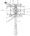
図1〜図7が、第1の典型的な実施の形態による二重フラップ装置1を示している。二重フラップ装置1が、第1のハウジング半分10および第2のハウジング半分20で構成され、両者の間に解除可能な接続を生み出すことができる。図1〜3において、ハウジング半分10、20は、互いから離され、互いに対して流れの方向に向けられた状態で図示されている。図4〜図7は、ハウジング半分10、20が互いに当接した状態の二重フラップ装置1を示している。この状態において、互いにドッキングしたハウジング半分10、20も説明される。
1 to 7 show a
図1〜図7によるハウジング半分10、20が互いに当接した場合に、二重フラップ装置1を、非ロック位置とロック位置との間で調節することができる。
The
図4が、非ロック位置にある二重フラップ装置1を示している。図5〜図7が、ロック位置にある二重フラップ装置1を示している。
FIG. 4 shows the
ロック位置において、二重フラップ装置1は、調節装置40によって閉鎖位置(図5および図6)と開放位置(図7)との間を枢動可能である。開放位置においては、二重フラップ12、22が、流れの方向Dに向けられる。
In the locked position, the
第1のハウジング半分10は、流れの方向Dの一方の側の第1のレセプタクル3へとフランジによって取り付けられている。このフランジによる取り付けは、第1のハウジング半分10と管ソケットとの間の溶接接続であってよい。第1のハウジング半分10は、流れの方向Dに流れを通過または移動させるための穴を中央に有している。
The
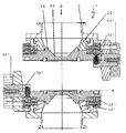
第1のレセプタクル3とは反対の側に、第1のハウジング半分10は、流れの方向Dに対して横方向である平面に位置する環状のシール用ワッシャ60を有している。第1のフラップ12が、回転軸Aを中心にして回転できるように、シール用ワッシャ60に取り付けられ、あるいは第1のハウジング半分10にシール用ワッシャ60を軸方向に貫いて取り付けられている。閉鎖位置において、第1のフラップ12が、第1のハウジング半分10を通過する流れが存在しないように穴を閉じる。回転軸Aは、レセプタクル3から遠ざかる方を向いたシール用ワッシャ60の表面上の閉鎖面11に位置している。回転軸Aと同軸に、第1の半シャフト14が、回転軸Aの方向に見たときの第1のフラップ12の両側において、第1のフラップ12へと接続されている。半シャフト14を、回転軸Aと同軸な方向に第1のフラップ12に一体に形成することも可能である。したがって、第1の半シャフト14は、その丸みを帯びた外周にてシール用ワッシャ60に位置し、シール用ワッシャ60において回転可能である。したがって、取り付けは、摺動軸受の形状にて実現される。代案として、特には回転をもたらす制御アクチュエータが組み込まれている他の取り付けも考えられる。
On the opposite side of the
第1の半シャフト14は、第1のフラップ12が第1のハウジング半分10から脱落することがあり得ないように、軸受要素38によって第1のハウジング半分10に保持されている。軸受要素38を、ブシュとして設計することができる。ブシュを受け入れるために、周方向に延びる溝が、第1のフラップ12から遠ざかる方を向いた端面において、半シャフト14に設けられている。
The
第1のフラップ12は、閉鎖面11の側においてわずかに凸状の設計であり、すなわち流れの方向Dの方向に第1のハウジング半分へとわずかに引っ込んでいる。第1のフラップ12の外周の領域において、フラップ12は、閉鎖面11の側に、シールリング50を取り付けることができる環状溝を有している。シールリング50は、特に好都合には、片側において隣接する第1の半シャフト14の表面の一部に及ぶように、第1のフラップ12の外周をわずかに超えて半径方向に広がる。
The
第1の半シャフト14の軸方向の延長において、第1のハウジング半分10は、回転軸Aの方向に見たときの内側から外側への両側に、調節装置40およびロック装置30を有している。各側の調節装置40が、該当の第1の半シャフト14を一緒に回転するように保持するとともに、自身はロック装置30に少なくとも部分的に回転可能に取り付けられている。したがって、2つの装置30、40は、回転軸Aを中心にして互いに独立して回転可能である。
In the axial extension of the
第1のフラップ12は、第1のレセプタクル3に面して、中央の領域への第1の凹所16を有しており、したがって第1のフラップ12は、中央の領域において可能な限り薄くなるように設計されている。凹所16は、第1のプレート12の外周に向かって可能な限り遠くまで延びている。凹所16の半径方向外側の壁は、第1のハウジング半分10の穴の内側の輪郭の流れを妨げない(flow−friendly)連続部として延びており、この連続部は、所定の管状の断面を大きくは変化させず、随意によりこの段面をわずかに先細りにしている。
The
原則として、第2のハウジング半分20は、第1のハウジング半分10に一致した方法で第1のハウジング半分10と同様に構成される。装置30、40の代わりに、第2のハウジング半分20は、第2のフラップ12の両側の第2の半シャフト24の軸方向の延長にロック要素32を有している。ロック要素32は、外側の輪郭に関して、半円柱の形状に設計されており、したがって第1のハウジング半分10のロック装置30が、ロックが行われるときにロック要素32をぴったりと合った様相で囲むことができる。
In principle, the
2つのハウジング半分10、20を、互いに解除可能に接続でき、あるいは互いにドッキングさせることができる。この目的のために、ハウジング半分10、20を、それぞれの回転軸に関して、共通の回転軸Aを有するように互いに対して向けなければならない。
The two
ハウジング半分10、20が互いに対して向けられたとき、対向する斜面34が、ロック装置30の半分開いた周壁に、軸Aに平行な向きに形成される。ドッキングの際に、ロック要素32が、斜面34に案内されてロック装置30内の同軸な位置へと滑り込む。
When the
精密な調節のために、閉鎖面11を貫く円錐形の先細りの調節ニップル36が、第1の半シャフト14に一体に形成され、あるいは第1の半シャフト14に固定されている。調節ニップル36に対向する位置の対応する第2の半シャフト24の心出し穴360が、調節ニップル36を受け入れるように意図されている。斜面34および円錐形の先細りの心出しニップル36のキャッチ領域が、わずかに重なり合ってドッキング時のハウジング半分10、20の良好な案内を保証するように設計されている。
For precise adjustment, a conical tapered
2つのハウジング半分10、20の軸受要素38の各々が、一緒の回転のためにハウジング半分10、20に配置されている。ハウジング半分10、20がドッキングさせられ、回転軸が互いに当接する場合、軸受要素38も、その外周の一部分によって互いに当接する。このようにして、半シャフト14、24の回転の際に、回転の進行において、一方のハウジング半分10の軸受要素38が、他方のハウジング半分20の半シャフト14、24の対応する溝に係合し、その逆も然りである。
Each of the bearing
ロック装置30を、ロック用レバー31によって回転させることができ、調節装置40を、制御レバー42によって回転させることができる。そのような構成または手動制御要素の別の構成に加えて、例えば空気式、油圧式、または電気式のアクチュエータなど、自動制御要素を代わりに使用してもよい。
The locking
図8〜図11が、第2の典型的な実施の形態による二重フラップ装置1’を、図2、図4、図6、および図7の動作位置に相当する図にて示している。
FIGS. 8 to 11 show a
二重フラップ装置1’は、ハウジング半分10’、20’への装置30’、40’の配置によって実質的に異なっている。閉鎖フラップ12’、24’のレセプタクルは、第1の典型的な実施の形態と実質的に同一に設計されている。 The double flap device 1 'differs substantially depending on the arrangement of the devices 30', 40 'in the housing halves 10', 20 '. The receptacles of the closure flaps 12 ', 24' are designed substantially the same as in the first exemplary embodiment.
第2の典型的な実施の形態においては、ハウジング半分10’、20’が、同一の設計であり、したがってこれらのハウジング半分を、互いに対して180°回転させ、互いに対して精密に一致させ、互いによって閉じることができる。ロック装置30’および調節装置40’が、第1または第2のハウジング半分10’、20’の各側にペアにて分配されている。結果として、各々のハウジング半分10’、20’が、それと反対の側に、ロック要素32’、ロック用レバー31’、および制御レバー42’を有している。
In a second exemplary embodiment, the
結果として、第2の典型的な実施の形態のレバー31’、42’の配置が第1の典型的な実施の形態と比べて異なっていても、二重フラップの形状の第1および第2のフラップ12’、22’について、図11による開位置への回転を達成することができる。 As a result, the first and second in the form of a double flap, even though the arrangement of levers 31 ', 42' of the second exemplary embodiment is different compared to the first exemplary embodiment. For the flaps 12 ', 22', rotation to the open position according to FIG. 11 can be achieved.
図12〜図14が、それぞれ2つの眺めおよび詳細図にて示されたシールリング50を示している。フラップ12、12’、22、22’および半シャフト14、24の密封におけるシールリング50の機能の成就は、半シャフト14、24の間でのシールリング50の膨張によって達成される。この目的のために、シールリング50は、回転軸Aの方向の両側に位置する周上の向かい合う部位Wにおいて幅がより広い設計である。フラップ12、12’、22、22’の枢動を可能にするために、シールリング50の直径は、フラップ12、12’、22、22’のフラップ直径よりも小さくなければならず、あるいは最大でも同じ直径でなければならない。シールリング50は、この幅の広い部位Wを半シャフト14、24の間に位置づける。
FIGS. 12-14 show the
特に好都合には、シールリング50の側壁が、角度βおよびγで斜めであるように設計される。それぞれの部位Wにおいて、シールリング50は、部位Wのシールリング50を受け入れる半シャフト14、24の方向へとシールリップ52によって半径方向外側へと広げられている。シールリップ52は、受け入れの半シャフト14、24に向かって角度αに傾けられている。
Particularly advantageously, the side walls of the
1、1’ 二重フラップ装置
3 第1のレセプタクル
5 第2のレセプタクル
10、10’ 第1のハウジング半分
11 閉鎖面
12、12’ 第1のフラップ
14 第1の半シャフト
15 シャフト
16 第1の凹所
20、20’ 第2のハウジング半分
22、22’ 第2のフラップ
24 第2の半シャフト
26 第2の凹所
30、30’ ロック装置
31、31’ ロック用レバー
32、32’ ロック要素
33 溝状ガイド
34 斜面
36 調節ニップル
38 軸受要素
40、40’ 調節装置
42、42’ 制御レバー
50 シールリング
52 シールリップ
60 シール用ワッシャ
360 心出し穴
α 角度
A 回転軸
D 流れの方向
R 直径
W 部位
DESCRIPTION OF
Claims (10)
解除可能な接続を間に生み出すことができる2つのハウジング半分(10、10’;20、20’)と、
ハウジング半分(10、10’;20、20’)ごとに1つのフラップ(12、12’;22、22’)とを備えており、前記フラップが、半シャフト(14、24)によって該当のハウジング半分(10、10’;20、20’)に枢動可能に取り付けられ、
二重フラップ装置(1,1’)が接続位置にあるときに、ハウジング半分(10、10’;20、20’)およびフラップ(12、12’;22、22’)が互いに当接して互いを補強し、
2つのフラップ(12、12’;22、22’)の半シャフト(14,24)が、回転軸(A)を有する共通のシャフト(15)を形成するようにぴったり合い、両方のフラップ(12、12’;22、22’)を、共通のシャフト(15)を介して調節装置(40、40’)によって閉鎖位置と開放位置との間で枢動させることができ、開放位置において流動性を有する製品を第1のレセプタクル(3)から第2のレセプタクル(5)へと流れの方向(D)に移動させることができる二重フラップ装置(1、1’)であり、
それぞれの半シャフト(14)の軸方向の延長において、第1のハウジング半分(10、10’)が、少なくともそれぞれのフラップ(12、12’)の片側に、二重フラップ装置(1、1’)を非ロック位置とロック位置との間で調節することができるロック装置(30、30’)を有しており、ロック装置(30、30’)が、ハウジング半分(10、10’;20、20’)の間の解除可能な接続を生み出すとともに、ハウジング半分(10、10’;20、20’)を互いに対して補強することを特徴とする二重フラップ装置(1、1’)。 A double flap device (1, 1 ') for connecting the two receptacles (3, 5) without leakage to the surrounding environment,
Two housing halves (10, 10 '; 20, 20') between which a releasable connection can be created;
Each of the housing halves (10, 10 ′; 20, 20 ′) with one flap (12, 12 ′; 22, 22 ′), said flap being the corresponding housing by a half shaft (14, 24) Half (10, 10 '; 20, 20') pivotally mounted;
When the double flap device (1, 1 ′) is in the connected position, the housing halves (10, 10 ′; 20, 20 ′) and the flaps (12, 12 ′; 22, 22 ′) abut against each other. Reinforced,
The half shafts (14, 24) of the two flaps (12, 12 '; 22, 22') fit snugly to form a common shaft (15) having an axis of rotation (A) and both flaps (12 , 12 '; 22, 22') can be pivoted between a closed position and an open position by means of an adjusting device (40, 40 ') via a common shaft (15), in which the fluidity is A double flap device (1, 1 ') capable of moving a product having a flow direction (D) from a first receptacle (3) to a second receptacle (5);
In the axial extension of each half-shaft (14), the first housing half (10, 10 ') is at least on one side of each flap (12, 12') with a double flap device (1, 1 '). ) Can be adjusted between an unlocked position and a locked position, the locking device (30, 30 ′) being a housing half (10, 10 ′; 20). , 20 ′) and a double flap device (1, 1 ′) characterized in that the housing halves (10, 10 ′; 20, 20 ′) are reinforced against each other.
Applications Claiming Priority (3)
| Application Number | Priority Date | Filing Date | Title |
|---|---|---|---|
| DE102009025290.8 | 2009-06-15 | ||
| DE200910025290 DE102009025290A1 (en) | 2009-06-15 | 2009-06-15 | Double flap device for the environmentally sealed connection of two containers |
| PCT/EP2010/003591 WO2010145804A1 (en) | 2009-06-15 | 2010-06-15 | Dual flap device for the environmentally tight connection of two receptacles |
Publications (1)
| Publication Number | Publication Date |
|---|---|
| JP2012530218A true JP2012530218A (en) | 2012-11-29 |
Family
ID=42938315
Family Applications (1)
| Application Number | Title | Priority Date | Filing Date |
|---|---|---|---|
| JP2012514395A Ceased JP2012530218A (en) | 2009-06-15 | 2010-06-15 | Double flap device for connecting two receptacles without leaking to the surrounding environment |
Country Status (5)
| Country | Link |
|---|---|
| US (1) | US8590557B2 (en) |
| EP (1) | EP2443054B1 (en) |
| JP (1) | JP2012530218A (en) |
| DE (1) | DE102009025290A1 (en) |
| WO (1) | WO2010145804A1 (en) |
Families Citing this family (9)
| Publication number | Priority date | Publication date | Assignee | Title |
|---|---|---|---|---|
| DE202007013676U1 (en) * | 2007-09-28 | 2008-02-28 | Gea Niro Gmbh | Docking device consisting of two coupling closures for the environmentally sound transfer of bulk material, comprising at least one locking unit |
| DE102011009303A1 (en) * | 2010-09-24 | 2012-03-29 | Andocksysteme G. Untch Gmbh | Multiple flap device for a contamination-free connection of two containers or lines as well as passive and active flap for this purpose |
| GB201203559D0 (en) * | 2012-02-29 | 2012-04-11 | Chargepoint Technology Ltd | Improvements relating to valves |
| JP5415647B1 (en) * | 2013-08-21 | 2014-02-12 | 株式会社ミウラ | Split valve |
| SI25176A (en) * | 2016-04-14 | 2017-10-30 | Brinox D.O.O. | Floating beared divided valve flap |
| DE102017104975A1 (en) | 2017-03-09 | 2018-09-13 | Thomas Schneider | Transfer filling |
| DE102018008536A1 (en) * | 2018-10-31 | 2020-04-30 | Merck Patent Gmbh | Process and device for the introduction of solids into process plants |
| EP3821974A1 (en) | 2019-11-13 | 2021-05-19 | Bachem AG | Apparatus for iterative polymer synthesis |
| CN114321432B (en) * | 2022-03-03 | 2022-05-10 | 山东天成阀门制造有限公司 | Prevent leaking self sealss ball valve |
Citations (4)
| Publication number | Priority date | Publication date | Assignee | Title |
|---|---|---|---|---|
| JP2004507416A (en) * | 2000-08-28 | 2004-03-11 | ゲーエーアー ブック ヴァルブ ゲゼルシャフト ミット ベシュレンクテル ハフツング | Apparatus for connecting two storage means and / or transport means by a fixed holding device |
| JP2006057758A (en) * | 2004-08-20 | 2006-03-02 | Seishi Kurimoto | Valve incorporating pipe joint |
| JP2010512286A (en) * | 2006-12-15 | 2010-04-22 | ゲーエーアー ファーマ システムズ アーゲー | Coupling device comprising a coupling closure and two coupling closures |
| WO2010092395A1 (en) * | 2009-02-12 | 2010-08-19 | Powder Systems Limited | Split valve |
Family Cites Families (6)
| Publication number | Priority date | Publication date | Assignee | Title |
|---|---|---|---|---|
| US5295507A (en) * | 1992-01-29 | 1994-03-22 | Eli Lilly And Company | Containment valve that allows contamination free transfer |
| DE10010995A1 (en) * | 2000-01-21 | 2001-08-02 | L B Bohle Maschinen Und Verfah | Method for connecting tank uses movable sealing plate in tank outlet and second movable plate in inlet of another tank, inlet and outlet being connected, sealed with plates and space between them being evacuated |
| DE20014872U1 (en) * | 2000-08-28 | 2001-01-25 | Gea Powder Technology Gmbh | Device for coupling two storage and / or conveying means with a cleaning device |
| ITLU20000007A1 (en) | 2000-11-30 | 2002-05-30 | Mech Design Di Ing Fabrizio Bellin I E Ing Edoar | VALVE WITH CONFINING SYSTEM VIA CONNECTION OF SEMI-ELEMENTS THAT FORM WITH THEM A SINGLE FUNCTIONAL ELEMENT, OF EASY ASSEMBLY AND DISASSEMBLY. |
| NL1017697C2 (en) * | 2001-03-26 | 2002-09-27 | Solid Proc Systems Holding B V | Valve extraction. |
| DE102008049129A1 (en) | 2008-09-26 | 2010-04-08 | Gea Niro Gmbh | Coupling closure and fastening module and docking device, each containing this coupling closure |
-
2009
- 2009-06-15 DE DE200910025290 patent/DE102009025290A1/en not_active Withdrawn
-
2010
- 2010-06-15 WO PCT/EP2010/003591 patent/WO2010145804A1/en active Application Filing
- 2010-06-15 JP JP2012514395A patent/JP2012530218A/en not_active Ceased
- 2010-06-15 EP EP20100744680 patent/EP2443054B1/en not_active Not-in-force
- 2010-06-15 US US13/378,483 patent/US8590557B2/en not_active Expired - Fee Related
Patent Citations (4)
| Publication number | Priority date | Publication date | Assignee | Title |
|---|---|---|---|---|
| JP2004507416A (en) * | 2000-08-28 | 2004-03-11 | ゲーエーアー ブック ヴァルブ ゲゼルシャフト ミット ベシュレンクテル ハフツング | Apparatus for connecting two storage means and / or transport means by a fixed holding device |
| JP2006057758A (en) * | 2004-08-20 | 2006-03-02 | Seishi Kurimoto | Valve incorporating pipe joint |
| JP2010512286A (en) * | 2006-12-15 | 2010-04-22 | ゲーエーアー ファーマ システムズ アーゲー | Coupling device comprising a coupling closure and two coupling closures |
| WO2010092395A1 (en) * | 2009-02-12 | 2010-08-19 | Powder Systems Limited | Split valve |
Also Published As
| Publication number | Publication date |
|---|---|
| EP2443054B1 (en) | 2013-03-13 |
| DE102009025290A1 (en) | 2010-12-16 |
| WO2010145804A1 (en) | 2010-12-23 |
| US8590557B2 (en) | 2013-11-26 |
| US20120111443A1 (en) | 2012-05-10 |
| EP2443054A1 (en) | 2012-04-25 |
Similar Documents
| Publication | Publication Date | Title |
|---|---|---|
| JP2012530218A (en) | Double flap device for connecting two receptacles without leaking to the surrounding environment | |
| RU2530695C2 (en) | Compound valve | |
| JP5766786B2 (en) | Valve shaft equipment for use with rotary valves | |
| US8360103B2 (en) | Split valve | |
| US8813795B2 (en) | Passive valve for multivalve devices and a multivalve device, in particular having such a passive valve | |
| JPH094713A (en) | Separable coupling device for two component having non-circular contour, particularly elliptical contour | |
| US9631762B2 (en) | Connection element with sealing member | |
| CN108698810B (en) | Extraction fitting for a liquid container | |
| CN207843996U (en) | Device for discharging for moving feed bin | |
| US20160319993A1 (en) | Fluid system connection nozzle assembly | |
| JP2010540362A (en) | Docking device with two coupling closures and at least one locking unit for transferring bulk material in an environmentally sealed state | |
| JPH09177735A (en) | Device for connecting container | |
| CA2836435C (en) | Breakaway coupling for a liquid line | |
| EP2535630A1 (en) | Half butterfly valves quick-release coupling | |
| JP5451195B2 (en) | Fitting and header device | |
| AU2009307773A2 (en) | Handle shaft assemblies for bottom loading couplers | |
| KR101789985B1 (en) | Plugging device | |
| US9534699B2 (en) | Lower effort quick-connect coupler | |
| US11852246B2 (en) | Valve assembly and method of producing the same | |
| US20180106409A1 (en) | Lower effort quick-connect coupler | |
| JP2008100766A (en) | Closure system for use in closing flap | |
| JP2024501460A (en) | Connection assembly for liquid-tight transfer containers | |
| CN206830886U (en) | Check valve | |
| JPS62220796A (en) | Combination device of quick safety connection release mechanism for piping and control valve | |
| SE539472C2 (en) | A coupling device for establishing a fluid connection between a first container and a second container |
Legal Events
| Date | Code | Title | Description |
|---|---|---|---|
| A621 | Written request for application examination |
Free format text: JAPANESE INTERMEDIATE CODE: A621 Effective date: 20130530 |
|
| A131 | Notification of reasons for refusal |
Free format text: JAPANESE INTERMEDIATE CODE: A131 Effective date: 20140311 |
|
| A521 | Request for written amendment filed |
Free format text: JAPANESE INTERMEDIATE CODE: A523 Effective date: 20140609 |
|
| A01 | Written decision to grant a patent or to grant a registration (utility model) |
Free format text: JAPANESE INTERMEDIATE CODE: A01 Effective date: 20141209 |
|
| A045 | Written measure of dismissal of application [lapsed due to lack of payment] |
Free format text: JAPANESE INTERMEDIATE CODE: A045 Effective date: 20150421 |