JP2012529342A - Intraocular illumination using low power laser light - Google Patents
Intraocular illumination using low power laser light Download PDFInfo
- Publication number
- JP2012529342A JP2012529342A JP2012514957A JP2012514957A JP2012529342A JP 2012529342 A JP2012529342 A JP 2012529342A JP 2012514957 A JP2012514957 A JP 2012514957A JP 2012514957 A JP2012514957 A JP 2012514957A JP 2012529342 A JP2012529342 A JP 2012529342A
- Authority
- JP
- Japan
- Prior art keywords
- laser light
- light source
- laser
- handpiece
- eye
- Prior art date
- Legal status (The legal status is an assumption and is not a legal conclusion. Google has not performed a legal analysis and makes no representation as to the accuracy of the status listed.)
- Pending
Links
Images
Classifications
-
- A—HUMAN NECESSITIES
- A61—MEDICAL OR VETERINARY SCIENCE; HYGIENE
- A61F—FILTERS IMPLANTABLE INTO BLOOD VESSELS; PROSTHESES; DEVICES PROVIDING PATENCY TO, OR PREVENTING COLLAPSING OF, TUBULAR STRUCTURES OF THE BODY, e.g. STENTS; ORTHOPAEDIC, NURSING OR CONTRACEPTIVE DEVICES; FOMENTATION; TREATMENT OR PROTECTION OF EYES OR EARS; BANDAGES, DRESSINGS OR ABSORBENT PADS; FIRST-AID KITS
- A61F9/00—Methods or devices for treatment of the eyes; Devices for putting-in contact lenses; Devices to correct squinting; Apparatus to guide the blind; Protective devices for the eyes, carried on the body or in the hand
- A61F9/007—Methods or devices for eye surgery
- A61F9/008—Methods or devices for eye surgery using laser
- A61F2009/00861—Methods or devices for eye surgery using laser adapted for treatment at a particular location
- A61F2009/00863—Retina
-
- A—HUMAN NECESSITIES
- A61—MEDICAL OR VETERINARY SCIENCE; HYGIENE
- A61F—FILTERS IMPLANTABLE INTO BLOOD VESSELS; PROSTHESES; DEVICES PROVIDING PATENCY TO, OR PREVENTING COLLAPSING OF, TUBULAR STRUCTURES OF THE BODY, e.g. STENTS; ORTHOPAEDIC, NURSING OR CONTRACEPTIVE DEVICES; FOMENTATION; TREATMENT OR PROTECTION OF EYES OR EARS; BANDAGES, DRESSINGS OR ABSORBENT PADS; FIRST-AID KITS
- A61F9/00—Methods or devices for treatment of the eyes; Devices for putting-in contact lenses; Devices to correct squinting; Apparatus to guide the blind; Protective devices for the eyes, carried on the body or in the hand
- A61F9/007—Methods or devices for eye surgery
- A61F9/008—Methods or devices for eye surgery using laser
- A61F2009/00861—Methods or devices for eye surgery using laser adapted for treatment at a particular location
- A61F2009/00874—Vitreous
-
- A—HUMAN NECESSITIES
- A61—MEDICAL OR VETERINARY SCIENCE; HYGIENE
- A61F—FILTERS IMPLANTABLE INTO BLOOD VESSELS; PROSTHESES; DEVICES PROVIDING PATENCY TO, OR PREVENTING COLLAPSING OF, TUBULAR STRUCTURES OF THE BODY, e.g. STENTS; ORTHOPAEDIC, NURSING OR CONTRACEPTIVE DEVICES; FOMENTATION; TREATMENT OR PROTECTION OF EYES OR EARS; BANDAGES, DRESSINGS OR ABSORBENT PADS; FIRST-AID KITS
- A61F9/00—Methods or devices for treatment of the eyes; Devices for putting-in contact lenses; Devices to correct squinting; Apparatus to guide the blind; Protective devices for the eyes, carried on the body or in the hand
- A61F9/007—Methods or devices for eye surgery
- A61F9/008—Methods or devices for eye surgery using laser
- A61F9/00821—Methods or devices for eye surgery using laser for coagulation
Abstract
眼科手術システムは、レーザ治療モードと照明モードとを有するレーザ光源を含む。レーザ治療モードは第1の出力を有し、照明モードは、第1の出力よりも小さい第2の出力を有する。また、眼科手術コンソールは、照明モードにおいてレーザ光源を光ガイドに光学的に結合するように使用可能な合焦光学素子を含む。 The ophthalmic surgical system includes a laser light source having a laser treatment mode and an illumination mode. The laser treatment mode has a first output and the illumination mode has a second output that is less than the first output. The ophthalmic surgical console also includes focusing optics that can be used to optically couple the laser light source to the light guide in the illumination mode.
Description
関連出願の相互参照
本出願は、参照によって本明細書の一部を構成する、2009年6月10日出願の米国仮特許出願第61/185,756号および2010年4月7日出願の米国非仮特許出願第12/755,479号の優先権の利益を主張する。
CROSS REFERENCE TO RELATED APPLICATIONS This application is hereby incorporated by reference, US Provisional Patent Application No. 61 / 185,756 filed on June 10, 2009 and US application filed April 7, 2010. Claims the benefit of priority of non-provisional patent application 12 / 755,479.
本発明は、眼科手術で使用される照明器に関し、特に、眼の内部を照明するのに適した光を生成する眼内照明器に関する。 The present invention relates to an illuminator used in ophthalmic surgery, and more particularly to an intraocular illuminator that generates light suitable for illuminating the interior of the eye.
解剖学的には、眼は、前房と後房という2つの別個の部分に分けられる。前房は、水晶体を含み、角膜(角膜内皮)のもっとも外側の層から水晶体嚢の後方に延びる。後房は水晶体嚢の背後の眼の部分を含む。後房は、前房の硝子体面から網膜に延び、網膜と硝子体の後方の硝子体面と直接接触している。後房は前房よりもはるかに大きい。 Anatomically, the eye is divided into two separate parts, the anterior chamber and the posterior chamber. The anterior chamber contains the lens and extends from the outermost layer of the cornea (corneal endothelium) to the back of the lens capsule. The posterior chamber contains the part of the eye behind the capsular bag. The posterior chamber extends from the vitreous surface of the anterior chamber to the retina and is in direct contact with the retina and the vitreous surface behind the vitreous. The posterior chamber is much larger than the anterior chamber.
後房は硝子体を含むが、これは無色透明のゲル状の物質である。硝子体は、眼の体積のおよそ3分の2を占め、出生前に眼を形成している。硝子体は1%のコラーゲンおよびヒアルロン酸ナトリウムと99%の水から構成されている。硝子体の前方境界は前方硝子体面であって、これは水晶体の後嚢に接触しており、後方硝子体面は、その後方境界を形成しており、網膜に接触している。硝子体は、房水のように流動性を有さず、通常の解剖学的付着部位を有する。こうした部位の1つは硝子体基底部であるが、これは鋸状縁の上に重なる3〜4mm幅の帯である。視神経乳頭、黄斑、および血管アーケードも付着部位である。硝子体の主な機能は、網膜を定位置に保持し、球体の完全性と形状を維持し、移動による衝撃を吸収し、水晶体を後方から支持することである。房水と対照的に、硝子体は常に交換されるものではない。硝子体は、離液として知られる過程において、年齢と共により流動的になる。離液の結果、硝子体は収縮してその正常な付着部位に圧力または牽引力を及ぼすことがある。十分な牽引力が適用されると、硝子体は、網膜に付着しなくなり、網膜の裂傷や孔を生じさせることがある。 The posterior chamber contains a vitreous body, which is a colorless and transparent gel-like substance. The vitreous occupies approximately two-thirds of the eye volume and forms the eye before birth. The vitreous is composed of 1% collagen and sodium hyaluronate and 99% water. The anterior boundary of the vitreous is the anterior vitreous surface, which is in contact with the posterior capsule of the lens, and the posterior vitreous surface forms its posterior boundary and is in contact with the retina. The vitreous body is not fluid like aqueous humor and has a normal anatomical attachment site. One such site is the vitreous basal, which is a 3-4 mm wide band that overlies the serrated edge. The optic disc, macular, and vascular arcade are also attachment sites. The main function of the vitreous body is to hold the retina in place, maintain the integrity and shape of the sphere, absorb the impact of movement, and support the lens from the back. In contrast to aqueous humor, the vitreous is not always exchanged. The vitreous body becomes more fluid with age in a process known as syneresis. As a result of lysing, the vitreous can contract and exert pressure or traction on its normal attachment site. When sufficient traction is applied, the vitreous no longer adheres to the retina and can cause retinal tears and holes.
硝子体網膜処置と呼ばれる、様々な外科処置は普通眼の後房で行われる。硝子体網膜処置は後房の多くの深刻な症状を治療するのに適している。硝子体網膜処置は、加齢性黄斑変性(AMD)、糖尿病性網膜症および糖尿病性硝子体出血、円孔、網膜剥離、網膜前膜、CMV網膜炎、および多くの他の眼科症状のような症状を治療する。1つの通常の硝子体網膜処置は光凝固(photocoagulation)療法である。光凝固療法では、高強度のレーザ光の使用によって眼の中のタンパク質を加熱して網膜の裂傷を修復し、剥離に帰結しうる異常な網膜血管系の成長を防止する。光凝固処置では、外科医は、アルゴンイオンレーザのようなレーザ源に結合されたレーザハンドピースを使用してレーザ光を目標部位に適用する。 Various surgical procedures, called vitreous retinal procedures, are usually performed in the posterior chamber of the eye. Vitreous retinal treatment is suitable for treating many serious symptoms of the posterior chamber. Vitreous retinal treatments such as age-related macular degeneration (AMD), diabetic retinopathy and diabetic vitreous hemorrhage, hole, retinal detachment, preretinal membrane, CMV retinitis, and many other ophthalmic symptoms Treat symptoms. One common vitreous retinal procedure is photocoagulation therapy. Photocoagulation therapy uses high-intensity laser light to heat proteins in the eye to repair retinal tears and prevent abnormal retinal vasculature growth that can result in detachment. In a photocoagulation procedure, a surgeon applies laser light to a target site using a laser handpiece coupled to a laser source, such as an argon ion laser.
外科医は、顕微鏡と、後房の鮮明な映像を提供するように設計された専用レンズとによって硝子体網膜処置を行う。毛様体扁平部の強膜に長さ1ミリメートルほどのいくつかの小さな切開部を作る。外科医は、切開部を通して、顕微手術器具、例えば、眼の内部を照明する光ファイバ光源と、手術中眼の形状を維持する注入ラインと、硝子体を切断して除去する器具とを挿入する。 The surgeon performs the vitreous retinal procedure with a microscope and a dedicated lens designed to provide a clear image of the posterior chamber. Make several small incisions about 1 mm long in the sclera of the ciliary flat part. The surgeon inserts through the incision a microsurgical instrument such as a fiber optic light source that illuminates the interior of the eye, an injection line that maintains the shape of the eye during surgery, and an instrument that cuts and removes the vitreous.
こうした外科処置の際、眼の内部を適切に照明することは重要である。通常、細い光ファイバを眼に挿入して照明を提供する。メタルハライドランプ、ハロゲンランプ、キセノンランプ、または水銀ランプのような光源を使用して、光ファイバによって眼に伝えられる光を生成することが多い。光は、いくつかの光学要素(通常レンズ、ミラー、および減衰器)を通過して、光を眼に伝える光ファイバに放出される。この光の品質は、選択された光学要素の種類を含むいくつかの要因に依存する。 During such surgical procedures, it is important to properly illuminate the interior of the eye. Usually, a thin optical fiber is inserted into the eye to provide illumination. Light sources such as metal halide lamps, halogen lamps, xenon lamps, or mercury lamps are often used to generate light that is transmitted to the eye by optical fibers. Light passes through several optical elements (usually lenses, mirrors, and attenuators) and is emitted into an optical fiber that carries the light to the eye. This light quality depends on several factors, including the type of optical element selected.
本発明の特定の実施形態では、眼科手術システムは、レーザ治療モードと照明モードとを有するレーザ光源を含む。レーザ治療モードは第1の出力を有し、照明モードは、第1の出力よりも小さい第2の出力を有する。また、眼科手術コンソールは、照明モードにおいてレーザ光源を光ガイドに光学的に結合するように使用可能な合焦光学素子を含む。 In certain embodiments of the invention, the ophthalmic surgical system includes a laser light source having a laser treatment mode and an illumination mode. The laser treatment mode has a first output and the illumination mode has a second output that is less than the first output. The ophthalmic surgical console also includes focusing optics that can be used to optically couple the laser light source to the light guide in the illumination mode.
本発明の他の実施形態では、眼の内部を照明する方法は、レーザ治療モードと照明モードとを有するレーザ光源を提供するステップを含む。レーザ治療モードは第1の出力を有し、照明モードは、第1の出力よりも小さい第2の出力を有する。本方法は、さらに、眼内照明器ハンドピースをレーザ光源に光学的に結合するステップと、外科的切開部を通して眼内照明器ハンドピースを眼内に挿入するステップとを含む。本方法は、その後、照明モードにおいてレーザ光源からのレーザ光を使用して眼の内部を照明するステップを含む。 In another embodiment of the invention, a method of illuminating the interior of an eye includes providing a laser light source having a laser treatment mode and an illumination mode. The laser treatment mode has a first output and the illumination mode has a second output that is less than the first output. The method further includes optically coupling the intraocular illuminator handpiece to a laser light source and inserting the intraocular illuminator handpiece into the eye through a surgical incision. The method then includes illuminating the interior of the eye using laser light from a laser light source in illumination mode.
本発明の実施形態の様々な態様は、以下の詳細な説明から明らかになるだろう。
本発明およびその利点をさらに完全に理解するために、添付の図面と共に以下の説明を参照する。全図を通じて同一参照符号は同一のものを表す。
本発明の好適実施形態を図面に例示する。各図の同一参照符号は、同一および対応するものを表すために使用される。
Various aspects of embodiments of the present invention will become apparent from the following detailed description.
For a more complete understanding of the present invention and the advantages thereof, reference is made to the following description taken in conjunction with the accompanying drawings, in which: Throughout the drawings, the same reference numerals denote the same parts.
Preferred embodiments of the invention are illustrated in the drawings. The same reference numbers in each figure are used to denote the same and corresponding items.
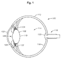
図1は、本発明によって提供される改良設計の眼の移植物が配置されうる眼の解剖図を例示する。眼100は、角膜102、虹彩104、瞳孔106、水晶体108、水晶体嚢110、毛様小帯、毛様体120、強膜112、硝子体ゲル114、網膜116、黄斑、および視神経120を含む。角膜102は眼の表面にある透明なドーム形の構造で、眼に光を導入する窓の役目を果たす。虹彩104は、眼の色の付いた部分で、虹彩と呼ばれ、瞳孔を取り巻く筋肉であって、弛緩したり緊張したりして眼に入る光の量を制御している。瞳孔106は、虹彩の円形の中心開口である。水晶体108は、網膜上に光の焦点を合わせるのを補助する眼内の構造である。水晶体嚢110は、水晶体を取り巻く弾性の嚢であり、眼が様々な距離の対象に焦点を合わせるときに水晶体の形状を制御するのを補助する。毛様小帯は、水晶体嚢を眼の内部に取り付け、水晶体を定位置に保持する細い襞である。毛様体は、水晶体に取り付けられた筋肉領域であり、収縮したり弛緩したりして水晶体の大きさを制御して焦点を合わせる。強膜112は、眼球の形状を維持する眼の強靱なもっとも外側の層である。硝子体ゲル114は、眼球の後方に向かって位置する、ゲルで満たされた部分であり、眼の曲率を維持するのを補助する。網膜116は、眼の後方の感光性の神経層であり、光を受け取って信号に変換し脳に送る。黄斑は、細部を見るための感覚器官を含む網膜の領域である。視神経118は眼からの信号を脳に接続して伝達する。
FIG. 1 illustrates an anatomical view of an eye in which an improved design eye implant provided by the present invention may be placed.
毛様体122は虹彩104のすぐ後ろにある。毛様体122には、毛様小帯124と呼ばれるごく小さな繊維の「ガイドワイヤ」が取り付けられている。水晶体108は、毛様小帯124によって眼の内部に懸垂されている。毛様体122のための栄養は、虹彩104に栄養を供給している血管と同じ血管から来る。毛様体122の機能の1つは、水晶体108の形状を変化させて遠近調節を制御することである。毛様体122が収縮すると、毛様小帯124は弛緩する。これによって、水晶体108は、厚くなり、近くに焦点を合わせる眼の能力を増大する。遠方の物体を見る時は、毛様体122は弛緩して、毛様小帯124を収縮させる。すると、水晶体108は薄くなり、遠方を見るように眼の焦点を調整する。
The
普通、網膜116は、眼に進入する光をフィルタリングする眼の生来の水晶体108によって紫外線から保護される。しかし、光学眼内照明器からの光は、水晶体によるフィルタリングがない状態で(すなわち、無水晶体の状態で)眼に進入し、この光が、電磁スペクトルの紫外線領域または赤外線領域に近い十分強い成分を含む場合、眼組織を損傷することがある。有害な短波長および長波長をフィルタリングしつつ照明のための適切な範囲の可視光波長範囲を提供することによって、青色光による網膜の光化学的損傷、赤外線による加熱損傷、および同様の光毒性の危険因子を含む、無水晶体の危険因子によって網膜を損傷するリスクを大幅に減らすことができる。通常、約430〜700ナノメートルの範囲内の光が、こうした危険因子のリスクを減らすために好適である。
Normally, the
しかし、十分な光強度を達成するため、以前の眼内照明器は広範なスペクトルの光源によるものであった。例えば、多くの眼内照明の光源は、ハロゲンタングステンランプまたは高圧アークランプ(メタルハライドランプ、Xe)を使用している。アークランプの利点は、放出領域が小さく(<1mm)、色温度が日光に近く、50時間に対して400時間と寿命がハロゲンランプよりも長いことである。アークランプの欠点は、コストが高く、光出力が弱く、システムが複雑であり、システムの寿命が過ぎる間に何回もランプの交換が必要になるという点である。LEDによる照明器はコストおよび複雑さを大幅に下げることができ、定格寿命は50,000〜100,000時間なので、出力の低下がほとんどない状態でLEDを交換する必要なく器具の寿命の全期間眼ファイバ照明器を動作させることができるだろう。通常の白色LEDは、白色蛍光体キャップを励起して眼内照明器のための十分な白色光を生成する紫外線(UV)/紫色/青色LEDを含んでもよい。 However, in order to achieve sufficient light intensity, previous intraocular illuminators were from a broad spectrum light source. For example, many intraocular light sources use halogen tungsten lamps or high pressure arc lamps (metal halide lamps, Xe). The advantages of arc lamps are that the emission area is small (<1 mm), the color temperature is close to sunlight, and the lifetime is 400 hours for 50 hours, longer than the halogen lamp. Disadvantages of arc lamps are that they are expensive, have low light output, are complex in system, and require many lamp replacements during the lifetime of the system. LED illuminators can significantly reduce cost and complexity, with a nominal life of 50,000-100,000 hours, so the entire life of the appliance is not required to replace the LED with little loss of power An optical fiber illuminator could be operated. A typical white LED may include an ultraviolet (UV) / purple / blue LED that excites a white phosphor cap to generate sufficient white light for the intraocular illuminator.
従来の照明器と異なり、本発明の様々な実施形態は、低出力レーザ光を使用する照明を提供する。これは眼組織に有害となりうる電磁スペクトルの成分を回避しつつ可視光スペクトルで十分な照明を提供する。可視領域のコントラストを改善すべく、低出力レーザ照明器で使用される光の波長を選択できることは有利である。すなわち、例えば、Alcon Laboratories,Inc.が製造するPUREPOINT(登録商標)光凝固器のようなある種の光凝固器で使用されるレーザ光源は、約532nmの波長を有する緑色レーザ光を生成できる(本出願で使用される場合「約」という用語は、定格波長の±5nm以内のレーザ光を均一に生成するという意味である)。以前の眼内照明器と比較して、この波長の光を吸収した結果生じる明暗の範囲によって、網膜血管系と他の光学組織との間の視覚的コントラストを改善することができる。 Unlike conventional illuminators, various embodiments of the present invention provide illumination using low power laser light. This provides sufficient illumination in the visible light spectrum while avoiding components of the electromagnetic spectrum that can be detrimental to ocular tissue. Advantageously, the wavelength of light used in the low power laser illuminator can be selected to improve the contrast in the visible region. That is, for example, Alcon Laboratories, Inc. The laser light source used in certain photocoagulators, such as the PUREPOINT® photocoagulator manufactured by the company, can produce green laser light having a wavelength of about 532 nm (as used in this application “about” "Means that the laser light within ± 5 nm of the rated wavelength is uniformly generated). Compared to previous intraocular illuminators, the range of light and dark resulting from absorbing light of this wavelength can improve the visual contrast between the retinal vasculature and other optical tissues.
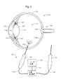
図2は、眼内照明器160の断面図であるが、これは眼内に配置された、本発明の様々な実施形態の何れかに係る眼内照明器でもよい。図2は、使用中のハンドピース162の付いたハンドピース164を示す。ハンドピース162は、毛様体扁平領域の切開部を通して眼100に挿入される。ハンドピース162は、眼100の内部または硝子体領域114を照明する。この状態で、ハンドピース162を使用して、硝子体−網膜の手術の間、内部または硝子体領域を照明できる。ハンドピース162は、通常光ファイバである光ガイド168によってレーザ光源166に接続されている。合焦光学素子170は、レーザ光源166から放出されたレーザビームを光ガイド168に結合する。合焦光学素子170は、レーザ光源166または関連する眼科手術コンソールの内部または外部のどちらに配置してもよい。光ガイド168は、当該技術分野で公知の任意の望ましいコア、クラッディング、ドーパント、屈折率、熱特性、機械的特性、または他の特性を有する、レーザ光源166によって生成された波長の光を伝えるのに適した任意の導管を含むことができる。眼科用途で使用されるガラスまたはプラスチックの光ファイバは、典型的には、直径が、治療用放射を提供する場合50〜300μmであり、照明を提供する場合400〜750μmの範囲である。
FIG. 2 is a cross-sectional view of the
レーザ光源166は、眼組織の視覚化を可能にする十分な強度の可視スペクトルの波長のコヒーレントレーザ光を生成するための任意の適切な装置でよい。特定の実施形態では、レーザ光源166は、およそ532nmの波長を有する緑色レーザ光を生成する。また、レーザ光源166は、レーザ治療用ハンドピース172に結合してもよい。レーザ治療用ハンドピース172も、眼内照明器ハンドピース162について説明したものと同様であるが、眼組織に光化学変化を生成するために使用されるレーザ光を伝えるのに適した、対応する光ガイド174を含んでもよい。また、合焦光学素子170は、レーザ光源166をレーザ治療用ハンドピース172に結合する個別および/または構成要素を含んでもよい。特定の実施形態では、眼内照明器ハンドピース162とレーザ治療用ハンドピース172とは、組み合わされた単一のハンドピースに統合されてもよい。
The
動作する際、レーザ光源166は、異なる2つの動作モードを有する。第1のモードは、ビームスポットの標的となる眼組織の比較的小さな範囲内に、レーザ光の吸収によって生成される熱効果のような光化学変化を生成するのに十分な、眼組織に入射するレーザビームのための出力密度を有するレーザ治療モードである。特定の実施形態では、こうした光化学変化を使用して、網膜組織の断裂または剥離を修復したり、網膜内の異常な血管系の成長を阻止することができる。特定の実施形態では、レーザ治療モードは、眼組織のタンパク質の熱変化による網膜組織の凝集を生成する光凝固モードでもよい。第2のモードは照明モードである。照明モードでは、レーザ光を使用して、外科手術のための対象部位の周囲の手術分野を照明する。照明モードは、網膜組織の特性が変化しないような低出力を使用する。大部分の用途では、スポットサイズは、外科手術の対象部位を取り囲む範囲の視界を提供するためレーザ治療モードのためのスポットサイズよりかなり大きくてもよいが、狭角照明の用途では、スポットサイズは同等のことがある。
In operation, the
一例では、レーザ光源166は光凝固のためにも使用される。通常の光凝固の用途では、眼組織に熱変化を生成するために使用されるレーザ出力は、網膜上の1mm程度のスポットサイズの場合少なくとも100mWであり、レーザビームは、5mmの推定作業距離で放出され、生理的食塩水媒体中で伝達される。こうした用途では、例えば、レーザ光源166を使用して、開口数を持つ光ファイバに結合される50μm以下のスポットサイズを生み出し、網膜上に1mmのスポットサイズを生成してもよい。
In one example, the
光凝固のために必要な強度とは異なり、十分な照明のために必要な最小強度は、医師毎に異なることがあるため明確ではない。眼手術で使用される以前に市販された照明器は、手術分野において、普通の照明の場合12ルーメンまで、広角照明の場合15ルーメン以上の光束を生成したが、特に眼内照明器によって生成される光束の関数としての対象手術部位の実効放射照度が点光源と比較して高くなるように有利に構成されている場合、最大値の10%の光束レベルでも十分なことがあった。 Unlike the intensity required for photocoagulation, the minimum intensity required for sufficient illumination is not clear because it may vary from doctor to doctor. Previously commercially available illuminators used in ophthalmic surgery have produced a luminous flux in the surgical field of up to 12 lumens for normal illumination and 15 lumens or more for wide angle illumination, but in particular produced by intraocular illuminators. If the effective irradiance of the target surgical site as a function of the luminous flux is advantageously configured to be higher than that of the point light source, a luminous flux level of 10% of the maximum value may be sufficient.
上記で概説したような一般的な要求を前提に、レーザ光源166の照明モードのための出力レベルを選択することができる。レーザは、特有の波長で比較的高い変換効率を有することが多いので、普通比較的低い出力で高いレベルの光束を生み出すことができる。すなわち、およそ600ルーメン/Wという容易に達成可能な変換効率の場合、同じ最大光束を生成するために必要な出力はわずか約20〜25mWでよい。光凝固器のための通常の眼科用レーザ光源は100〜600mWの範囲で動作する。しかし、約30mW〜2Wの範囲で動作し、その下端が既存の照明器のピーク出力に近く、大きく修正することなく照明モードで機能させることができる、Alcon Laboratories,Inc.によって製造されたPUREPOINT(登録商標)レーザ光源のようないくつかの既存のレーザ光源が存在する。狭角用途の場合、出力レベルは原則としてさらに低くてもよく、一般には、10nW〜50mWの出力レベルが多くの用途の適切な出力レベルをカバーする好適な範囲であろう。
Given the general requirements outlined above, the power level for the illumination mode of the
眼組織に対する無水晶体の危険因子を減らすという観点で、眼損傷のリスクは、白色光を使用する従来の眼内照明器と比較して評価することができる。上記のように、従来の白色光眼内照明器は、12〜15ルーメンの範囲内の光束レベルで無水晶体にとって安全と考えられている。1時間を越える手術で使用される場合でも、こうした器具の場合、網膜組織の損傷は認められなかった。単一波長付近の狭い放出プロファイルを有するレーザの場合、無水晶体の危険因子となる範囲のスペクトルの成分の強度は大幅に低下する。例えば、532nmのレーザ光をXeバルブ照明器と比較した場合、無水晶体の危険因子の電磁放射の網膜に対する合計放射照度はほぼ12分の1に下がるだろう。すなわち、同程度の照明の場合、眼組織を損傷するリスクは従来の眼内照明器よりも低いはずである。 In terms of reducing aphakic risk factors for ocular tissue, the risk of eye damage can be assessed compared to conventional intraocular illuminators that use white light. As noted above, conventional white light intraocular illuminators are considered safe for aphakic bodies at light flux levels in the range of 12-15 lumens. Even when used for more than one hour of surgery, no damage to the retinal tissue was observed with these instruments. In the case of a laser with a narrow emission profile near a single wavelength, the intensity of the spectral components in the range that is a risk factor for the lens is greatly reduced. For example, when comparing 532 nm laser light to a Xe bulb illuminator, the total irradiance on the retina of the aphakic risk factor electromagnetic radiation would be reduced by almost a factor of 12. That is, with comparable illumination, the risk of damaging ocular tissue should be lower than conventional intraocular illuminators.
レーザ光照明器に固有の1つの問題は光ガイド168に対する熱損傷の可能性である。眼内照明器は通常、柔軟で眼内に眼内照明器を容易に配置することができるプラスチックの光ファイバを使用する。光は、通常およそ0.5という、ビームの比較的高い開口数(NA)を持つプラスチック照明器に結合され、手術分野で十分に大きなスポットサイズを生成する。しかし、光凝固のような用途において使用されるレーザビームは、非常に小さなスポットサイズで放出されることが多いので、斯かる高開口数を有するファイバに結合すると比較的低いレーザ出力でさえもビームウエストにおいてきわめて強い放射照度を生じるだろう。プラスチックの光ファイバがこの強い放射照度を吸収すると、プラスチックがその溶融温度まで加熱され、ファイバが破損することがある。
One problem inherent with laser light illuminators is the possibility of thermal damage to the
したがって、白色光源を眼内照明器のファイバに結合するための従来の光学素子を使用する場合とは異なり、レーザ眼内照明器の合焦光学素子170は、プラスチックの眼内照明器のファイバに強い放射照度のスポットが形成されるのを防止するように構成されるべきである。ファイバ上のこうした強いスポットを防止するためには、望ましいNAを維持しつつ、入射ビームのサイズを拡大してできる限り密にファイバ開口を満たすのが有利である。すなわち、例えば、円筒形石英ロッド(cylindrical quartz rod)が、レーザビームの焦点における近位端と、光ガイド168の近位端に対して当接される遠位端とを有して配置されることができ、このことによって、光ガイド168に供給される光の合計強度を大きく低下させることなくビームをかなり大きなスポットサイズに拡散させることができる。別の例では、散乱プレートを使用してもよい。
Thus, unlike using conventional optics to couple the white light source to the fiber of the intraocular illuminator, the focusing
また、場合によっては、照明の範囲を比較的狭くするのが望ましいことがあり、これは何らかの構造を照明するのに有用なことがある。こうした場合、レーザ光源166を照明モードにしたままで低い開口数の治療用ファイバに結合して、治療ビームよりもはるかに低い強度の比較的小さな照明スポットを生成するようにしてもよい。こうした実施形態では、手術中にレーザ治療用ハンドピース172が眼内にある時にレーザ光源166を治療モードと照明モードとの間で切り換えることが可能であり、ハンドピース172内の個別の照明用および治療用のファイバを必要とすることなく単一のハンドピース172によって照明および治療を提供することができる。
Also, in some cases it may be desirable to have a relatively narrow illumination range, which may be useful for illuminating some structure. In such a case, the
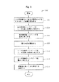
図3は、本発明の特定の実施形態に係る光学眼内照明器によって眼を照明する方法の一例を例示するフローチャート300である。ステップ302では、上記の様々な実施形態に関連して説明したような、レーザ治療モードと照明モードとを有するレーザ光源166が提供される。ステップ304では、眼内照明器ハンドピース162がレーザ光源166に光学的に結合される。ステップ306では、ハンドピース162が、外科的切開部を通して眼に挿入される。ステップ308では、ハンドピースを使用して眼の内部が照明される。
FIG. 3 is a
ステップ310では、レーザ治療用ハンドピース172がレーザ光源166に光学的に結合され、ステップ312ではレーザ治療用ハンドピース172が切開部を通して眼に挿入される。ステップ314では、レーザ光源166からのレーザ光を使用して眼の組織の光化学変化が生成される。特定の方法を詳細に説明したが、上記で説明した眼科手術システムの様々な実施形態と矛盾しないやり方で、様々なステップを再配置および/または省略してもよく、また別のステップを追加してもよいことを理解されたい。すなわち、こうした眼科手術システムを使用する任意の適切な方法が本開示の範囲内において考えられる。
In
本発明を例示によって説明したが、当業者は様々な修正を行うことができる。例えば、ある出力パワーレベルをハンドピースに生成すべく付属の減衰器をレーザ光源に結合することによってレーザ光源の低出力モードを達成してもよい。本発明を詳細に説明したが、特許請求の範囲から逸脱することなく、様々な変更、置換および修正がなされうることが理解されるべきである。 Although the present invention has been described by way of example, those skilled in the art can make various modifications. For example, a low power mode of the laser light source may be achieved by coupling an attached attenuator to the laser light source to produce a certain output power level on the handpiece. Although the invention has been described in detail, it should be understood that various changes, substitutions and modifications can be made without departing from the scope of the claims.
Claims (20)
レーザ治療モードと照明モードとを有するレーザ光源であって、前記レーザ治療モードが第1の出力を有し、前記照明モードが、前記第1の出力よりも小さい第2の出力を有する、レーザ光源と、
前記照明モードにおいて前記レーザ光源を光ガイドに光学的に結合するように使用可能な合焦光学素子と
を備える眼科手術システム。 An ophthalmic surgery system,
A laser light source having a laser treatment mode and an illumination mode, wherein the laser treatment mode has a first output, and the illumination mode has a second output smaller than the first output. When,
An ophthalmic surgical system comprising focusing optics that can be used to optically couple the laser light source to a light guide in the illumination mode.
レーザ治療モードと照明モードとを有するレーザ光源を提供するステップであって、前記レーザ治療モードが第1の出力を有し、前記照明モードが、前記第1の出力よりも小さい第2の出力を有する、ステップと、
眼内照明器ハンドピースを前記レーザ光源に光学的に結合するステップと、
外科切開部を通して前記眼内照明器ハンドピースを前記眼内に挿入するステップと、
前記照明モードにおいて前記レーザ光源からのレーザ光を使用して前記眼の内部を照明するステップと
を含む方法。 In a method of illuminating the interior of the eye,
Providing a laser light source having a laser treatment mode and an illumination mode, wherein the laser treatment mode has a first output, and the illumination mode has a second output smaller than the first output. Having a step;
Optically coupling an intraocular illuminator handpiece to the laser light source;
Inserting the intraocular illuminator handpiece through the surgical incision into the eye;
Illuminating the interior of the eye using laser light from the laser light source in the illumination mode.
前記レーザ治療モードにおいて前記レーザ光源からのレーザ光を使用して前記眼の組織において光化学変化を生成するステップとを含む、請求項12に記載の方法。 Optically coupling a laser therapy handpiece to the laser light source;
And generating photochemical changes in the tissue of the eye using laser light from the laser light source in the laser therapy mode.
レーザ治療モードと照明モードとを有するレーザ光源であって、前記レーザ治療モードが少なくとも100mWの第1の出力を有し、前記照明モードが10nW〜50mWの第2の出力を有し、約532nmの波長を有するレーザ光を生成するように使用可能なレーザ光源と、
眼内照明器ハンドピースと、
前記レーザ光源を前記眼内照明器ハンドピース内の光ガイドに光学的に結合する合焦光学素子と
を備える眼科手術システム。 An ophthalmic surgery system,
A laser light source having a laser treatment mode and an illumination mode, wherein the laser treatment mode has a first output of at least 100 mW, the illumination mode has a second output of 10 nW to 50 mW, and is about 532 nm A laser light source that can be used to generate laser light having a wavelength;
An intraocular illuminator handpiece,
An ophthalmic surgical system comprising: a focusing optical element that optically couples the laser light source to a light guide in the intraocular illuminator handpiece.
Applications Claiming Priority (5)
| Application Number | Priority Date | Filing Date | Title |
|---|---|---|---|
| US18575609P | 2009-06-10 | 2009-06-10 | |
| US61/185,756 | 2009-06-10 | ||
| US12/755,479 US20100318074A1 (en) | 2009-06-10 | 2010-04-07 | Ophthalmic endoillumination using low-power laser light |
| US12/755,479 | 2010-04-07 | ||
| PCT/US2010/030324 WO2010144174A1 (en) | 2009-06-10 | 2010-04-08 | Ophthalmic endoillumination using low-power laser light |
Publications (2)
| Publication Number | Publication Date |
|---|---|
| JP2012529342A true JP2012529342A (en) | 2012-11-22 |
| JP2012529342A5 JP2012529342A5 (en) | 2013-05-16 |
Family
ID=43307061
Family Applications (1)
| Application Number | Title | Priority Date | Filing Date |
|---|---|---|---|
| JP2012514957A Pending JP2012529342A (en) | 2009-06-10 | 2010-04-08 | Intraocular illumination using low power laser light |
Country Status (7)
| Country | Link |
|---|---|
| US (1) | US20100318074A1 (en) |
| EP (1) | EP2440163A1 (en) |
| JP (1) | JP2012529342A (en) |
| CN (1) | CN102458321B (en) |
| AU (1) | AU2010259247A1 (en) |
| CA (1) | CA2761849A1 (en) |
| WO (1) | WO2010144174A1 (en) |
Cited By (1)
| Publication number | Priority date | Publication date | Assignee | Title |
|---|---|---|---|---|
| JP2014512851A (en) * | 2011-02-08 | 2014-05-29 | アルコン リサーチ, リミテッド | White coherent laser light emitted onto nanofibers for surgical lighting purposes |
Families Citing this family (11)
| Publication number | Priority date | Publication date | Assignee | Title |
|---|---|---|---|---|
| WO2011049853A1 (en) * | 2009-10-23 | 2011-04-28 | Shazly Tarek A | Surgical laser device utilizing a visible laser diode |
| US10226167B2 (en) | 2010-05-13 | 2019-03-12 | Beaver-Visitec International, Inc. | Laser video endoscope |
| US20160095507A1 (en) | 2010-05-13 | 2016-04-07 | Beaver-Visitec International, Inc. | Laser video endoscope |
| WO2012078943A1 (en) | 2010-12-09 | 2012-06-14 | Alcon Research, Ltd. | Optical coherence tomography and illumination using common light source |
| US9849034B2 (en) | 2011-11-07 | 2017-12-26 | Alcon Research, Ltd. | Retinal laser surgery |
| US10016302B2 (en) | 2014-06-19 | 2018-07-10 | Visumedics, Inc. | Diagnostic and surgical laser device utilizing a visible laser diode |
| US10702338B2 (en) | 2015-10-27 | 2020-07-07 | Visumedics, Inc. | Laser system with pulse modulation and corresponding method of use |
| WO2018091992A1 (en) * | 2016-11-21 | 2018-05-24 | Novartis Ag | Systems and methods using a vitreous visualization tool |
| US10537401B2 (en) * | 2016-11-21 | 2020-01-21 | Novartis Ag | Vitreous visualization system and method |
| JP2020511201A (en) * | 2017-02-28 | 2020-04-16 | アルコン インコーポレイティド | Multi-fiber multi-spot laser probe with simple tip structure |
| US10918522B2 (en) | 2017-06-08 | 2021-02-16 | Alcon Inc. | Photodisruption-based vitrectomy system |
Citations (5)
| Publication number | Priority date | Publication date | Assignee | Title |
|---|---|---|---|---|
| JPS61235807A (en) * | 1985-03-11 | 1986-10-21 | シレイ・インコーポレーテツド | Device for transmitting high-energy electromagnetic radiation over optical fiber from laser |
| JPH04500921A (en) * | 1988-10-07 | 1992-02-20 | スペクトラ・フィジックス・インコーポレイテッド | Diode laser equipment for eye surgery |
| JPH05297253A (en) * | 1992-04-17 | 1993-11-12 | Sony Corp | Coupled lens device |
| US20010016736A1 (en) * | 1998-11-10 | 2001-08-23 | Lin J. T. | Methods and apparatus for presbyopia treatment using a scanning laser system |
| JP2003111789A (en) * | 2001-10-03 | 2003-04-15 | Japan Science & Technology Corp | Probe for entoptic illumination and ophthalmic operating instrument |
Family Cites Families (59)
| Publication number | Priority date | Publication date | Assignee | Title |
|---|---|---|---|---|
| US4732148A (en) * | 1983-11-17 | 1988-03-22 | Lri L.P. | Method for performing ophthalmic laser surgery |
| US4607622A (en) * | 1985-04-11 | 1986-08-26 | Charles D. Fritch | Fiber optic ocular endoscope |
| US4820264A (en) * | 1985-05-01 | 1989-04-11 | Tokyo Kogaku Kikai Kabushiki Kaisha | Infusion instrument |
| US4865029A (en) * | 1986-04-24 | 1989-09-12 | Eye Research Institute Of Retina Foundation | Endophotocoagulation probe |
| US4818049A (en) * | 1987-06-10 | 1989-04-04 | Allied-Signal Inc. | Method and apparatus for efficiently conveying light over a distance and effecting controlled illumination by projection thereof |
| EP0501034A1 (en) * | 1991-01-30 | 1992-09-02 | CeramOptec GmbH | Illuminated leading probe device |
| US5151096A (en) * | 1991-03-28 | 1992-09-29 | Angiolaz, Incorporated | Laser catheter diffuser |
| US5331649A (en) * | 1991-07-10 | 1994-07-19 | Alson Surgical, Inc. | Multiple wavelength laser system |
| US5144630A (en) * | 1991-07-29 | 1992-09-01 | Jtt International, Inc. | Multiwavelength solid state laser using frequency conversion techniques |
| US5688264A (en) * | 1992-10-19 | 1997-11-18 | The University Of Miami | Laser treatment for retinal detachment |
| US5478338A (en) * | 1993-09-24 | 1995-12-26 | Reynard; Michael | Fiber optic sleeve for surgical instruments |
| US5624438A (en) * | 1994-05-09 | 1997-04-29 | Turner; R. Scott | Retinal wide-angle illuminator for eye surgery |
| US5531739A (en) * | 1994-09-23 | 1996-07-02 | Coherent, Inc. | Method of treating veins |
| US5713364A (en) * | 1995-08-01 | 1998-02-03 | Medispectra, Inc. | Spectral volume microprobe analysis of materials |
| US5921981A (en) * | 1995-11-09 | 1999-07-13 | Alcon Laboratories, Inc. | Multi-spot laser surgery |
| US5909602A (en) * | 1996-09-30 | 1999-06-01 | Sharp Kabushiki Kaisha | Image forming apparatus having a specimen image judging section and an image information suitability judging section |
| US6000813A (en) * | 1996-12-21 | 1999-12-14 | Krietzman; Mark Howard | Laser pointer with light shaping rotating disk |
| US6062702A (en) * | 1997-04-16 | 2000-05-16 | Krietzman; Mark Howard | Laser light |
| US5997163A (en) * | 1998-06-09 | 1999-12-07 | L E Systems Inc. | Mobile laser spotlight system for law enforcement |
| US6246817B1 (en) * | 1998-09-01 | 2001-06-12 | Innova Quartz Inc. | Optical fiber with numerical aperture compression |
| US6263879B1 (en) * | 1998-11-10 | 2001-07-24 | J. T. Lin | Treatment of presbyopia and other eye disorders using a scanning laser system |
| US6431731B1 (en) * | 1999-03-15 | 2002-08-13 | Mark Howard Krietzman | Laser device and method for producing diffuse illumination |
| US6186628B1 (en) * | 1999-05-23 | 2001-02-13 | Jozek F. Van de Velde | Scanning laser ophthalmoscope for selective therapeutic laser |
| US6640121B1 (en) * | 1999-08-10 | 2003-10-28 | The University Of Miami | Otic microprobe for neuro-cochlear monitoring |
| JP2001299941A (en) * | 2000-04-27 | 2001-10-30 | Hamamatsu Photonics Kk | Laser therapeutic device |
| CA2410962C (en) * | 2000-06-01 | 2015-08-04 | The General Hospital Corporation | An apparatus and method for performing selective photocoagulation |
| US20020087149A1 (en) * | 2001-01-03 | 2002-07-04 | Mccary Brian Douglas | Ophthalmic illumination device |
| US6887233B2 (en) * | 2001-03-22 | 2005-05-03 | Lumenis, Inc. | Scanning laser handpiece with shaped output beam |
| EP1829496A2 (en) * | 2001-12-10 | 2007-09-05 | Inolase 2002 Ltd. | Eyesafe hair removal method and apparatus |
| US20030169603A1 (en) * | 2002-03-05 | 2003-09-11 | Luloh K. Peter | Apparatus and method for illuminating a field of view within an eye |
| JP4054222B2 (en) * | 2002-06-05 | 2008-02-27 | オリンパス株式会社 | Light source device for endoscope device |
| US20040116909A1 (en) * | 2002-12-11 | 2004-06-17 | Ceramoptec Industries Inc. | Multipurpose diode laser system for ophthalmic laser treatments |
| CA2523777C (en) * | 2003-03-14 | 2016-05-10 | Light Sciences Corporation | Light generating device to intravascular use |
| US7150530B2 (en) * | 2003-05-21 | 2006-12-19 | Alcon, Inc. | Variable spot size illuminator having a zoom lens |
| ES2523964T3 (en) * | 2003-07-28 | 2014-12-03 | Synergetics, Inc. | Lighting and laser source |
| TW200517406A (en) * | 2003-10-29 | 2005-06-01 | Nippon Catalytic Chem Ind | Polymer, process for preparing the same, and use of the same |
| US20050234441A1 (en) * | 2004-03-30 | 2005-10-20 | Bisch Michael E | Guided and filtered user interface for use with an ophthalmic surgical system |
| US20060033926A1 (en) * | 2004-08-13 | 2006-02-16 | Artsyukhovich Alexander N | Spatially distributed spectrally neutral optical attenuator |
| EP1795798B1 (en) * | 2004-10-01 | 2013-07-03 | Nichia Corporation | Light-emitting device |
| ATE429170T1 (en) * | 2004-10-29 | 2009-05-15 | Alcon Inc | COLOR COMPENSATING RETINAL SAFETY FILTER |
| WO2006053273A2 (en) * | 2004-11-12 | 2006-05-18 | Alcon, Inc. | Optical fiber detection method and system |
| US20070147752A1 (en) * | 2005-06-10 | 2007-06-28 | Omniguide, Inc. | Photonic crystal fibers and systems using photonic crystal fibers |
| EP1926504B1 (en) * | 2005-09-21 | 2010-01-13 | SurModics, Inc. | In situ occluding compositions ncluding natural biodegradable polysaccharides |
| US20070073279A1 (en) * | 2005-09-29 | 2007-03-29 | Alcon, Inc. | Variable continuous wave laser |
| US8126302B2 (en) * | 2006-03-31 | 2012-02-28 | Novartis Ag | Method and system for correcting an optical beam |
| NL1031588C2 (en) * | 2006-04-13 | 2007-10-19 | D O R C Dutch Ophthalmic Res C | Eye surgical instrument. |
| US7474820B2 (en) * | 2006-04-27 | 2009-01-06 | Invuity, Inc. | Micro-optic adapters and tips for surgical illumination fibers |
| US8308716B2 (en) * | 2006-06-30 | 2012-11-13 | Novartis Ag | Apparatus and method for auto-titrating a laser |
| US20080108979A1 (en) * | 2006-11-03 | 2008-05-08 | William Telfair | Flush Tip Illuminating Laser Probe Treatment Apparatus |
| US20080108983A1 (en) * | 2006-11-07 | 2008-05-08 | Synergetics, Inc. | Dual Core Optic Fiber Illuminated Laser Probe |
| US20080175002A1 (en) * | 2007-01-23 | 2008-07-24 | Michael Papac | System and method for the removal of undesired wavelengths from light |
| US8109937B2 (en) * | 2007-02-23 | 2012-02-07 | Alcon Research, Ltd. | Surgical system for indication of media types |
| US20080207992A1 (en) * | 2007-02-28 | 2008-08-28 | Synergetics, Inc. | Microsurgical Illuminator with Adjustable Illumination |
| US7682027B2 (en) * | 2007-04-09 | 2010-03-23 | Alcon, Inc. | Multi-LED ophthalmic illuminator |
| US7980745B2 (en) * | 2007-07-03 | 2011-07-19 | Ramsey Shanbaky | Broad spectrum fiber optic base laser illumination |
| ES2399814T3 (en) * | 2009-01-21 | 2013-04-03 | Alcon Research, Ltd. | Endoillumination ophthalmic that uses light generated by fiber |
| US8903475B2 (en) * | 2009-03-08 | 2014-12-02 | Oprobe, Llc | Multi-function optical probe system for medical and veterinary applications |
| AU2010325048B2 (en) * | 2009-11-24 | 2015-04-02 | Alcon Inc. | Single-fiber multi-spot laser probe for ophthalmic endoillumination |
| EP2512322A4 (en) * | 2009-12-17 | 2013-09-18 | Alcon Res Ltd | Photonic lattice leds for ophthalmic illumination |
-
2010
- 2010-04-07 US US12/755,479 patent/US20100318074A1/en not_active Abandoned
- 2010-04-08 CA CA2761849A patent/CA2761849A1/en not_active Abandoned
- 2010-04-08 JP JP2012514957A patent/JP2012529342A/en active Pending
- 2010-04-08 AU AU2010259247A patent/AU2010259247A1/en not_active Abandoned
- 2010-04-08 EP EP10714739A patent/EP2440163A1/en not_active Withdrawn
- 2010-04-08 CN CN201080025492.XA patent/CN102458321B/en not_active Expired - Fee Related
- 2010-04-08 WO PCT/US2010/030324 patent/WO2010144174A1/en active Application Filing
Patent Citations (5)
| Publication number | Priority date | Publication date | Assignee | Title |
|---|---|---|---|---|
| JPS61235807A (en) * | 1985-03-11 | 1986-10-21 | シレイ・インコーポレーテツド | Device for transmitting high-energy electromagnetic radiation over optical fiber from laser |
| JPH04500921A (en) * | 1988-10-07 | 1992-02-20 | スペクトラ・フィジックス・インコーポレイテッド | Diode laser equipment for eye surgery |
| JPH05297253A (en) * | 1992-04-17 | 1993-11-12 | Sony Corp | Coupled lens device |
| US20010016736A1 (en) * | 1998-11-10 | 2001-08-23 | Lin J. T. | Methods and apparatus for presbyopia treatment using a scanning laser system |
| JP2003111789A (en) * | 2001-10-03 | 2003-04-15 | Japan Science & Technology Corp | Probe for entoptic illumination and ophthalmic operating instrument |
Cited By (1)
| Publication number | Priority date | Publication date | Assignee | Title |
|---|---|---|---|---|
| JP2014512851A (en) * | 2011-02-08 | 2014-05-29 | アルコン リサーチ, リミテッド | White coherent laser light emitted onto nanofibers for surgical lighting purposes |
Also Published As
| Publication number | Publication date |
|---|---|
| CN102458321B (en) | 2014-04-30 |
| CN102458321A (en) | 2012-05-16 |
| EP2440163A1 (en) | 2012-04-18 |
| WO2010144174A1 (en) | 2010-12-16 |
| CA2761849A1 (en) | 2010-12-16 |
| US20100318074A1 (en) | 2010-12-16 |
| AU2010259247A1 (en) | 2011-12-08 |
Similar Documents
| Publication | Publication Date | Title |
|---|---|---|
| JP5902623B2 (en) | Single fiber multi-spot laser probe for intraocular illumination | |
| JP2012529342A (en) | Intraocular illumination using low power laser light | |
| JP5457466B2 (en) | Ophthalmic end illumination using fiber-generated light | |
| JP5848348B2 (en) | Dual-mode illumination method for surgical instruments | |
| JP5453311B2 (en) | Illuminated lighting for surgical instruments | |
| US8992021B2 (en) | Laser illumination system | |
| US20220280343A1 (en) | Excimer laser fiber illumination | |
| JP2014512851A (en) | White coherent laser light emitted onto nanofibers for surgical lighting purposes | |
| US8333482B2 (en) | Ophthalmic endoillumination with light collector for white phosphor | |
| JP5715236B2 (en) | Device for enhancing the brightness of wavelength conversion elements |
Legal Events
| Date | Code | Title | Description |
|---|---|---|---|
| A521 | Written amendment |
Free format text: JAPANESE INTERMEDIATE CODE: A523 Effective date: 20130327 |
|
| A621 | Written request for application examination |
Free format text: JAPANESE INTERMEDIATE CODE: A621 Effective date: 20130327 |
|
| A977 | Report on retrieval |
Free format text: JAPANESE INTERMEDIATE CODE: A971007 Effective date: 20140129 |
|
| A131 | Notification of reasons for refusal |
Free format text: JAPANESE INTERMEDIATE CODE: A131 Effective date: 20140204 |
|
| A02 | Decision of refusal |
Free format text: JAPANESE INTERMEDIATE CODE: A02 Effective date: 20140701 |