JP2012525272A - Magnet rotation hard stop for robot - Google Patents
Magnet rotation hard stop for robot Download PDFInfo
- Publication number
- JP2012525272A JP2012525272A JP2012508526A JP2012508526A JP2012525272A JP 2012525272 A JP2012525272 A JP 2012525272A JP 2012508526 A JP2012508526 A JP 2012508526A JP 2012508526 A JP2012508526 A JP 2012508526A JP 2012525272 A JP2012525272 A JP 2012525272A
- Authority
- JP
- Japan
- Prior art keywords
- rotatable
- magnet assembly
- stationary
- rotating
- stop member
- Prior art date
- Legal status (The legal status is an assumption and is not a legal conclusion. Google has not performed a legal analysis and makes no representation as to the accuracy of the status listed.)
- Abandoned
Links
Images


Classifications
-
- B—PERFORMING OPERATIONS; TRANSPORTING
- B25—HAND TOOLS; PORTABLE POWER-DRIVEN TOOLS; MANIPULATORS
- B25J—MANIPULATORS; CHAMBERS PROVIDED WITH MANIPULATION DEVICES
- B25J15/00—Gripping heads and other end effectors
- B25J15/06—Gripping heads and other end effectors with vacuum or magnetic holding means
-
- B—PERFORMING OPERATIONS; TRANSPORTING
- B25—HAND TOOLS; PORTABLE POWER-DRIVEN TOOLS; MANIPULATORS
- B25J—MANIPULATORS; CHAMBERS PROVIDED WITH MANIPULATION DEVICES
- B25J9/00—Programme-controlled manipulators
- B25J9/10—Programme-controlled manipulators characterised by positioning means for manipulator elements
- B25J9/1005—Programme-controlled manipulators characterised by positioning means for manipulator elements comprising adjusting means
- B25J9/101—Programme-controlled manipulators characterised by positioning means for manipulator elements comprising adjusting means using limit-switches, -stops
-
- B—PERFORMING OPERATIONS; TRANSPORTING
- B25—HAND TOOLS; PORTABLE POWER-DRIVEN TOOLS; MANIPULATORS
- B25J—MANIPULATORS; CHAMBERS PROVIDED WITH MANIPULATION DEVICES
- B25J15/00—Gripping heads and other end effectors
- B25J15/06—Gripping heads and other end effectors with vacuum or magnetic holding means
- B25J15/0608—Gripping heads and other end effectors with vacuum or magnetic holding means with magnetic holding means
-
- H—ELECTRICITY
- H01—ELECTRIC ELEMENTS
- H01L—SEMICONDUCTOR DEVICES NOT COVERED BY CLASS H10
- H01L21/00—Processes or apparatus adapted for the manufacture or treatment of semiconductor or solid state devices or of parts thereof
- H01L21/67—Apparatus specially adapted for handling semiconductor or electric solid state devices during manufacture or treatment thereof; Apparatus specially adapted for handling wafers during manufacture or treatment of semiconductor or electric solid state devices or components ; Apparatus not specifically provided for elsewhere
- H01L21/677—Apparatus specially adapted for handling semiconductor or electric solid state devices during manufacture or treatment thereof; Apparatus specially adapted for handling wafers during manufacture or treatment of semiconductor or electric solid state devices or components ; Apparatus not specifically provided for elsewhere for conveying, e.g. between different workstations
- H01L21/67739—Apparatus specially adapted for handling semiconductor or electric solid state devices during manufacture or treatment thereof; Apparatus specially adapted for handling wafers during manufacture or treatment of semiconductor or electric solid state devices or components ; Apparatus not specifically provided for elsewhere for conveying, e.g. between different workstations into and out of processing chamber
- H01L21/67742—Mechanical parts of transfer devices
-
- Y—GENERAL TAGGING OF NEW TECHNOLOGICAL DEVELOPMENTS; GENERAL TAGGING OF CROSS-SECTIONAL TECHNOLOGIES SPANNING OVER SEVERAL SECTIONS OF THE IPC; TECHNICAL SUBJECTS COVERED BY FORMER USPC CROSS-REFERENCE ART COLLECTIONS [XRACs] AND DIGESTS
- Y10—TECHNICAL SUBJECTS COVERED BY FORMER USPC
- Y10T—TECHNICAL SUBJECTS COVERED BY FORMER US CLASSIFICATION
- Y10T74/00—Machine element or mechanism
- Y10T74/20—Control lever and linkage systems
- Y10T74/20207—Multiple controlling elements for single controlled element
- Y10T74/20305—Robotic arm
Abstract
【解決手段】
回転機構を非連続に360度を超えて回転させる回転ハードストップ組立体を提供する。所定の実施形態によると、ウェハ搬送ロボット等のロボットのショルダー軸に対して630度以上回転する組立体を用いる。回転ハードストップ組立体は、バネとして互いに対向する複数の磁石を含む。さまざまな実施形態によると、互いに対向する複数の磁石によって、非接触形式での係合が可能となり、接触時に雑音を発生させることがなく、時間が経過しても磨耗することがない。回転ハードストップ組立体は、ロボットの円筒座標系のどの回転方向からでも位置決めが可能である。
【選択図】 図3A[Solution]
A rotating hard stop assembly is provided that rotates the rotating mechanism discontinuously beyond 360 degrees. According to a predetermined embodiment, an assembly that rotates more than 630 degrees with respect to a shoulder axis of a robot such as a wafer transfer robot is used. The rotating hard stop assembly includes a plurality of opposing magnets as springs. According to various embodiments, a plurality of magnets facing each other allows engagement in a non-contact manner, does not generate noise during contact, and does not wear out over time. The rotating hard stop assembly can be positioned from any rotational direction in the robot's cylindrical coordinate system.
[Selection] Figure 3A
Description
本願は、米国特許出願第12/432,620号(出願日:2009年4月29日)に基づき優先権を主張する。当該出願の開示内容は全て、参照により本願に組み込まれる。 This application claims priority based on US patent application Ser. No. 12 / 432,620 (filing date: April 29, 2009). The entire disclosure of that application is incorporated herein by reference.
円筒形ロボットは、半導体プロセスにおけるウェハ搬送システム等のさまざまな用途で、物体を持ち上げて置くために用いられる。円筒形ロボットの軸と、径方向運動、回転運動および垂直運動を行なうロボットアームとによって、円筒座標系が形成される。360度を超える回転を行なうロボットは、運動の範囲が360度以下のロボットが必要とする運動回数よりも少ない運動回数で、または、運動回数を最小限に抑えて、物体を持ち上げて置くことが可能となるので、スループットを改善する。 Cylindrical robots are used to lift and place objects in various applications such as wafer transfer systems in semiconductor processes. A cylindrical coordinate system is formed by the axis of the cylindrical robot and the robot arm that performs radial motion, rotational motion, and vertical motion. Robots that rotate more than 360 degrees can lift and place objects with fewer or fewer movements than required by robots with a range of movement of 360 degrees or less. This will improve the throughput.
連続回転は、ロボットの運動およびスループットを最適化するためには有効であるが、電気および空気圧を利用するスリップリング組立体が必要となる。また、360度を超えて回転するとケーブルが破損したり絡まったりするので、標準的なケーブルをショルダー部を貫通させて利用することができない。ハードストップ組立体は、アームが過度に回転しないようにするために用いられるので、ショルダー部を貫通するケーブルおよび管状部材は限界を超えて過度に回転させられることはない。360度を超えて回転しないようにするために、所与の構造上の特徴を設けて、アームと共に回転する別の構造上の特徴と係合するように構成する。係合することによって、アームはいずれの方向にも過度に回転しないようになる。この結果、進路を逆にしてより長い経路を移動することが必要になり得る(例えば、260度から10度に移動するためには、110度ではなく250度移動する必要がある)。このため、エンバイロメント内でのロボットの到達可能範囲が制限されてしまう。360度を超えて非連続的に回転させるために、可動ハードストップを用いるとしてよい。 Continuous rotation is effective to optimize robot motion and throughput, but requires a slip ring assembly that utilizes electricity and air pressure. Further, since the cable is damaged or entangled when it is rotated beyond 360 degrees, a standard cable cannot be used through the shoulder portion. Since the hard stop assembly is used to prevent the arm from rotating excessively, the cable and tubular member passing through the shoulder are not excessively rotated beyond limits. To prevent rotation beyond 360 degrees, a given structural feature is provided and configured to engage another structural feature that rotates with the arm. Engaging prevents the arm from rotating excessively in either direction. As a result, it may be necessary to reverse the path and move on a longer route (eg, to move from 260 degrees to 10 degrees, it is necessary to move 250 degrees instead of 110 degrees). For this reason, the reachable range of the robot within the environment is limited. A movable hard stop may be used to rotate discontinuously beyond 360 degrees.
回転機構用の、非連続に360度を超えて回転させる回転ハードストップ組立体を提供する。所定の実施形態によると、ウェハ搬送ロボット等のロボットのショルダー軸について360度から720度の間で回転させる組立体を用いる。回転ハードストップ組立体は、対向する複数の磁石を備える。さまざまな実施形態によると、互いに対向する磁石によって、非接触方式の係合が実現され、接触時の雑音が発生することもなく、時間の経過に応じて磨耗することもない。回転ハードストップ組立体は、ロボット円筒座標系のいずれの回転方向からも所定の位置に到達することを可能とする。 A rotating hard stop assembly for a rotating mechanism that rotates discontinuously beyond 360 degrees is provided. According to certain embodiments, an assembly is used that rotates between 360 and 720 degrees about the shoulder axis of a robot, such as a wafer transfer robot. The rotating hard stop assembly includes a plurality of opposing magnets. According to various embodiments, the non-contact type engagement is realized by the magnets facing each other, no noise is generated at the time of contact, and it does not wear as time passes. The rotating hard stop assembly makes it possible to reach a predetermined position from any rotation direction of the robot cylindrical coordinate system.
本発明の一の側面は、Z軸を中心としたθ回転運動を行う機構において回転を制限する装置に関する。所定の実施形態によると、当該装置は、静止磁石組立体が装着されている静止部材と、静止部材に隣接して設けられており、且つ、回転可能磁石組立体が装着されている回転可能停止部材とを備え、静止磁石組立体は、1以上の磁石が長手方向に、第1の磁極が静止磁石組立体の第1の端部に位置し、第2の磁極が静止磁石組立体の第2の端部に位置するように配置されており、回転可能磁石組立体は、1以上の磁石が長手方向に、第3の磁極が回転可能磁石組立体の第1の端部に位置し、第4の磁極が回転可能磁石組立体の第2の端部に位置するように配置されており、回転可能磁石組立体は、静止磁石組立体と係合可能であり、回転可能停止部材は、静止部材と係合していない場合には、機構と共に回転するように構成されている。 One aspect of the present invention relates to an apparatus for limiting rotation in a mechanism that performs θ rotation about the Z axis. According to certain embodiments, the apparatus includes a stationary member that is mounted with a stationary magnet assembly, and a rotatable stop that is provided adjacent to the stationary member and that is mounted with a rotatable magnet assembly. A stationary magnet assembly, wherein the one or more magnets are in the longitudinal direction, the first magnetic pole is positioned at the first end of the stationary magnet assembly, and the second magnetic pole is the first magnet of the stationary magnet assembly. The rotatable magnet assembly has one or more magnets in the longitudinal direction and a third magnetic pole located at the first end of the rotatable magnet assembly, A fourth magnetic pole is disposed at a second end of the rotatable magnet assembly, the rotatable magnet assembly is engageable with the stationary magnet assembly, and the rotatable stop member is When not engaged with the stationary member, it is configured to rotate with the mechanism.
静止部材は、ロボットドライブの一部、例えば、ショルダー部であってよい。静止部材は、内面および/または外面が円形であってよい。静止磁石組立体は、各端部の磁極が回転可能組立体の磁極と対向するべく露出されるように、静止部材上に装着される。静止部材および静止磁石組立体は、静止磁石組立体に係合していない場合に回転可能磁石組立体を障害物のない経路で回転させるように構成されている。特定の実施形態によると、静止磁石組立体は、静止部材の内面から突出している。他の実施形態によると、静止磁石組立体は、静止部材の外面から突出しているとしてもよく、または、静止部材の表面の上方または下方に装着されているとしてもよい。所定の実施形態によると、静止部材には環状凹部またはその他の環状経路が画定されており、当該環状凹部または環状経路内に静止磁石組立体が設けられて、当該環状凹部または環状経路の周囲を回転磁石組立体が回転可能である。例えば、回転は一方向とするために露出されている磁極が1つのみである実施形態、または、磁極が物理的に露出していないが、非接触形式のバネとして機能するのに十分な特性を持つ実施形態もまた本発明の範囲内である。静止磁石組立体は、1以上の磁石を有するとしてよい。 The stationary member may be a part of the robot drive, for example, a shoulder portion. The stationary member may have a circular inner surface and / or outer surface. The stationary magnet assembly is mounted on the stationary member such that the poles at each end are exposed to face the poles of the rotatable assembly. The stationary member and stationary magnet assembly are configured to rotate the rotatable magnet assembly in an unobstructed path when not engaged with the stationary magnet assembly. According to certain embodiments, the stationary magnet assembly projects from the inner surface of the stationary member. According to other embodiments, the stationary magnet assembly may protrude from the outer surface of the stationary member, or may be mounted above or below the surface of the stationary member. According to certain embodiments, the stationary member has an annular recess or other annular path defined therein, and a stationary magnet assembly is provided in the annular recess or annular path to surround the annular recess or annular path. The rotating magnet assembly is rotatable. For example, an embodiment where only one magnetic pole is exposed to rotate in one direction, or a characteristic that is sufficient to function as a non-contact spring, although the magnetic pole is not physically exposed Embodiments having are also within the scope of the present invention. The stationary magnet assembly may have one or more magnets.
回転可能停止部材は、静止部材と係合していない場合に、機構と共に回転するように構成されている。特定の実施形態によると、回転可能停止部材は、機構上に、例えば、回転可能停止部材と機構との間に配置されているベアリング上に装着されている。回転可能停止部材は、環状部材であってよい。回転可能停止部材は、回転可能磁石組立体を含む。 The rotatable stop member is configured to rotate with the mechanism when not engaged with the stationary member. According to certain embodiments, the rotatable stop member is mounted on a mechanism, for example, on a bearing disposed between the rotatable stop member and the mechanism. The rotatable stop member may be an annular member. The rotatable stop member includes a rotatable magnet assembly.
静止磁石組立体は、選択された回転位置を越えて回転可能停止部材が回転しないよう止めるように、回転可能磁石組立体と係合可能である。所定の実施形態によると、当該装置は、選択された回転位置において前記第1の磁極に前記第3の磁極が近接して、前記選択された回転位置を越えて前記回転可能停止部材が回転しないよう止めるように、構成されている第4の磁極は、選択された回転位置において第2の磁極と近接して、回転停止部材の逆方向への回転を止めるとしてよい。 The stationary magnet assembly is engageable with the rotatable magnet assembly to stop the rotatable stop member from rotating beyond a selected rotational position. According to certain embodiments, the apparatus is such that the third magnetic pole is proximate to the first magnetic pole at a selected rotational position and the rotatable stop member does not rotate beyond the selected rotational position. The fourth magnetic pole configured so as to stop may be close to the second magnetic pole at the selected rotational position and stop rotation of the rotation stop member in the reverse direction.
回転可能磁石組立体は、両端の磁極が露出して静止組立体の磁極と向かい合うように、回転可能停止部材に装着される。回転可能停止部材および静止部材は、それぞれの磁石組立体の反発し合う磁極が係合時に近接するように、例えば、S極とS極、または、N極とN極とが近接するように構成されている。所定の実施形態によると、当該装置は、選択された回転位置を越えて機構が回転しないように止めるための追加の停止構造を備える。これは、切り込み、ピン等の任意のその他の停止構造であってよい。特定の実施形態によると、追加で磁石組立体を利用するとしてよい。 The rotatable magnet assembly is mounted on the rotatable stop member such that the magnetic poles at both ends are exposed and face the magnetic poles of the stationary assembly. The rotatable stop member and the stationary member are configured so that, for example, the S pole and the S pole, or the N pole and the N pole are close to each other so that the repulsive magnetic poles of the respective magnet assemblies are close to each other when engaged. Has been. According to certain embodiments, the apparatus includes an additional stop structure to stop the mechanism from rotating beyond a selected rotational position. This may be any other stop structure such as a notch, a pin or the like. In certain embodiments, an additional magnet assembly may be utilized.
特定の実施形態によると、機構は、θ回転運動が可能なロボットアーム機構またはその一部である。また、ロボットアーム機構は、径方向運動および垂直運動も可能である。 According to a particular embodiment, the mechanism is a robot arm mechanism capable of θ rotation or a part thereof. The robot arm mechanism is also capable of radial movement and vertical movement.
特定の実施形態によると、静止磁石組立体および回転磁石組立体が有する1以上の磁石は、静止磁石組立体の磁石の曲率が回転可能磁石組立体の磁石の曲率と一致するような円弧形状となっている。このような構成とすることによって、磁石間で発生する反発力を可能な限り全て、係合のために用いることができる。 According to a particular embodiment, the one or more magnets of the stationary magnet assembly and the rotating magnet assembly have an arc shape such that the curvature of the magnet of the stationary magnet assembly matches the curvature of the magnet of the rotatable magnet assembly. It has become. By setting it as such a structure, all the repulsive force which generate | occur | produces between magnets can be used for engagement as much as possible.
特定の実施形態によると、静止部材と回転可能停止部材とは、非接触方式で係合する。回転可能磁石組立体の磁極が回転して静止磁石組立体の磁極に近接する位置まで到達すると、係合する。(2つのS極、または、2つのN極の間で発生する)反発する磁力は、ベアリングまたはその他の力を克服して、回転可能停止部材が回転機構と共に回転できる程度に十分な大きさを持つ磁力である。 According to certain embodiments, the stationary member and the rotatable stop member engage in a non-contact manner. When the magnetic pole of the rotatable magnet assembly rotates and reaches a position close to the magnetic pole of the stationary magnet assembly, it engages. The repulsive magnetic force (generated between the two S poles or the two N poles) is large enough to overcome the bearing or other force and allow the rotatable stop member to rotate with the rotating mechanism. It is a magnetic force.
本発明の別の側面は、Z軸を中心としたθ回転運動を行う機構を回転させる方法であって、静止磁石組立体が装着されている静止部材と、静止部材に隣接しており、且つ、回転可能磁石組立体が装着されている回転可能停止部材とを利用する方法に関する。さまざまな実施形態によると、当該方法は、第1の回転方向に機構および回転可能停止部材を回転させる段階と、選択された回転位置において、回転可能停止部材と静止部材とを非接触形式で係合させて、回転可能停止部材の回転を止めて静止させる段階と、第1の回転方向に回転可能停止部材を超えて機構を回転させる段階とを備える。 Another aspect of the present invention is a method of rotating a mechanism that performs a θ rotational movement about the Z axis, the stationary member on which a stationary magnet assembly is mounted, and adjacent to the stationary member, and And a method of utilizing a rotatable stop member on which a rotatable magnet assembly is mounted. According to various embodiments, the method includes rotating the mechanism and the rotatable stop member in a first rotational direction and engaging the rotatable stop member and the stationary member in a non-contact manner at a selected rotational position. A step of stopping and stopping the rotation of the rotatable stop member, and a step of rotating the mechanism beyond the rotatable stop member in the first rotation direction.
特定の実施形態によると、当該方法は、第2の選択された回転位置において機構を停止させる段階と、その後に第2の回転方向で機構を回転させる段階とを備えるとしてよい。第2の回転方向は、第1の回転方向の逆方向である。回転可能停止部材および回転機構はその後、第2の回転方向に回転させるとしてよい。特定の実施形態によると、回転可能停止部材はその後、第3の選択された回転位置において、静止部材と係合する。回転機構はその後、第2の回転方向で回転可能停止部材を超えて回転させられる。 According to certain embodiments, the method may comprise stopping the mechanism at a second selected rotational position and then rotating the mechanism in a second rotational direction. The second rotation direction is the reverse direction of the first rotation direction. The rotatable stop member and the rotation mechanism may then be rotated in the second rotation direction. According to a particular embodiment, the rotatable stop member is then engaged with the stationary member at a third selected rotational position. The rotating mechanism is then rotated beyond the rotatable stop member in the second rotational direction.
さまざまな実施形態によると、当該方法は、第1の位置から基板を取得して第2の位置に基板を載置するために、および/または、第3の位置に基板を載置して第4の位置からウェハを取得するために用いられるとしてよい。 According to various embodiments, the method can include obtaining a substrate from a first location and placing the substrate in a second location and / or placing the substrate in a third location and placing the substrate in a third location. 4 may be used to acquire a wafer from a position.
本発明の別の側面は、基板搬送システムに関する。さまざまな実施形態によると、当該システムは、複数の取得位置および載置位置と、a)360度を超えて非連続回転を行うロボットアーム、および、b)磁石回転ハードストップ組立体を有する基板搬送ロボットとを備える。複数の取得位置および載置位置は、基板収納部、ロードロックおよび/または処理ステーションのさまざまな組み合わせを含むとしてよい。磁石回転ハードストップ組立体は、前記基板搬送ロボットのショルダー部と回転可能停止部材とを非接触形式で係合させるように構成されているとしてよい。 Another aspect of the present invention relates to a substrate transfer system. According to various embodiments, the system includes a substrate transport having a plurality of acquisition and placement positions, a) a robot arm that rotates discontinuously beyond 360 degrees, and b) a magnet rotating hard stop assembly. With a robot. The plurality of acquisition positions and placement positions may include various combinations of substrate storage, load locks, and / or processing stations. The magnet rotation hard stop assembly may be configured to engage the shoulder portion of the substrate transport robot and the rotatable stop member in a non-contact manner.
本発明の上述およびその他の特徴および利点は、添付図面を参照しつつ以下でより詳細に説明する。 The above and other features and advantages of the present invention will be described in more detail below with reference to the accompanying drawings.
以下に記載する本発明の詳細な説明では、本発明を完全に理解していただくべく数多くの具体的な実施形態を記載する。しかし、当業者には明らかであるように、本発明は、このような具体的且つ詳細な内容に基づかなくとも、または、別の構成要素またはプロセスを用いても実施され得る。また、公知のプロセス、手順および素子は、本発明の側面を不要にあいまいにすることを避けるべく、詳細な説明を省略している。 In the following detailed description of the present invention, numerous specific embodiments are set forth in order to provide a thorough understanding of the present invention. However, it will be apparent to those skilled in the art that the present invention may be practiced without such specific details and with other components or processes. In other instances, well known processes, procedures, and elements have not been described in detail in order to avoid unnecessarily obscuring aspects of the invention.
本明細書で説明する装置および方法は、Z軸を中心として回転可能部材または回転可能機構を360度より大きい角度で回転させるために用いられるとしてよい。説明のために、以下の記載では、回転可能機構を回転可能ロボットアームと呼ぶ。しかし、当業者であれば、本明細書で説明する回転磁石ハードストップ組立体はこれに限定されるものではなく、任意の回転可能機構について360度を超えて非連続的な回転を可能とするために用いられ得るものと理解されたい。 The apparatus and methods described herein may be used to rotate a rotatable member or rotatable mechanism about the Z axis at an angle greater than 360 degrees. For purposes of explanation, in the following description, the rotatable mechanism is referred to as a rotatable robot arm. However, those skilled in the art will not be limited to the rotating magnet hard stop assembly described herein, and allow discontinuous rotation beyond 360 degrees for any rotatable mechanism. It should be understood that it can be used for this purpose.
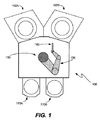
説明するように、本明細書に記載する装置および方法は、Z軸を中心としてロボットアームを360度より大きく(θ方向に360度より大きく)回転させるために用いられるとしてよい。特定の実施形態によると、当該装置および方法は、処理ステーション、ロードロック、収納部(例えば、正面開口式一体型ポッド(FOUP))等の間で半導体ウェハを移動させるために用いられる。図1は、本発明の実施形態に係るウェハ処理システム100を示す平面図である。システム100は、ロボット150と、1以上のロードロック102(つまり、102A、102B)と、1以上のウェハ収納部170(つまり、170A、170B)とを備える。
As will be described, the apparatus and method described herein may be used to rotate a robot arm greater than 360 degrees (greater than 360 degrees in the θ direction) about the Z axis. According to certain embodiments, the apparatus and method are used to move semiconductor wafers between processing stations, load locks, storage units (eg, front-opening integrated pods (FOUPs)), and the like. FIG. 1 is a plan view showing a
ロボット150は、ウェハ処理システムでウェハを取り扱うのに適しているマルチリンクロボットである。ロボット150は、ロードロック102および収納部170の間でウェハを移動させるように構成されている。ロボット150は、ロボットアーム130と、1以上のウェハを支持するためのエンドエフェクタ160とを有する。(また、ロボットは、複数のエンドエフェクタを有するとしてよく、説明を簡略化するため、1つのみ図示している。)ロボット150は、アーム130およびエンドエフェクタ160に回転機能(θ方向)を持たせるように構成されている。また、ロボットは、径方向運動機能(R、ロボット150の中心から径方向)、および、垂直方向運動機能(Z、高さ方向)をエンドエフェクタ160に持たせるように構成されているとしてよい。このため、ウェハを取得位置から持ち上げるためには、取得位置に対向するように回転して、ウェハより下方の位置まで降下して、取得位置まで延伸して、ウェハを持ち上げるために上昇するとしてよい。この後エンドエフェクタ160を後退させるとしてよく、ロボットアーム130およびエンドエフェクタ160を載置位置に対向するように回転させて、載置位置まで延伸して、ウェハを載置するために降下させるとしてよい。システム100は、本明細書に記載する装置および方法を採用し得るウェハ搬送システムの一例に過ぎない。例えば、特定の実施形態では、ロードロックおよび処理モジュールの間での搬送を行なうシステムで採用されるとしてもよい。
The
ロボット150は、360度を越える範囲での非連続回転機能をアーム130に持たせるように構成されている。ロボットアームの回転は概して、多くの方法で実現され得る。連続回転は、ロボットの運動およびスループットを最適化するためには有効であるが、電気および空気圧を利用したスリップリング組立体を必要とする。また、360度を超えて回転するとケーブルが破損したり絡まったりするので、標準的なケーブルをショルダー部を貫通させて利用することができない。ハードストップ組立体は、アームが過度に回転しないようにするために用いられるので、ショルダー部を貫通するケーブルおよび管状部材は限界を超えて過度に回転させられることはない。360度を超えて回転しないようにするために、所与の構造上の特徴を設けて、アームと共に回転する別の構造上の特徴と係合するように構成する。係合することによって、アームはいずれの方向にも過度に回転しないようになる。この結果、進路を逆にしてより長い経路を移動することが必要になり得る(例えば、260度から10度に移動するためには、110度ではなく250度移動する必要がある)。このため、図1に示したようなミニエンバイロメント内でのロボットの到達可能範囲が制限されてしまう。通常のロボットは、非連続回転の全範囲が約270度に過ぎず、360度未満である。360度を超えて回転させるには、以下でさらに説明するが、可動ハードストップを利用するとしてよい。しかし、回転するハードストップの衝撃を吸収するために軟性材料が利用されると、停止構造は高速移動時の慣性を吸収することができず、移動が早過ぎる場合にはクリック音が発生してしまう。また、軟性材料は損耗してしまい、早期に故障が発生してしまう可能性がある。
The
図2Aおよび図2Bは、特定の実施形態に係るロボット250を示す図である。図2Aは、ドライブ組立体筐体210と、ロボットアーム230と、エンドエフェクタ260とを備えるロボット250を示す側面図であり、図2Bは、筐体210と、エンドエフェクタを接続し得るロボットアーム230とを備えるロボット250を示す斜視図である。本明細書に記載する回転ハードストップ組立体および方法によれば、θ方向の長距離移動の速度を制限することなくロボットアームを360度を越えて回転させることが可能となる。この結果、連続回転可能な設計を採用すると、複雑なスリップリング組立体が必要で、且つ、標準的な高屈曲性のケーブルおよび管状部材をショルダー部の軸を貫通するように利用することが禁止されるが、このような連続回転可能な設計になっていなくても、処理ステーション、ロードロックまたはその他の取得/載置位置にどちらの回転方向からも到達可能となる。回転ハードストップ組立体は、最高で720度の回転角を(組立体のサイズによってのみ制限される)実現し、過度の回転を防止する。ハードストップ組立体は、停止用の非接触式バネとして機能する磁石を含む。磁石は、雑音を発生させることがなく、時間が経過しても磨耗しない。
2A and 2B are diagrams illustrating a
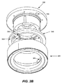
図3Aおよび図3Bは、本発明の一実施形態に係るロボット組立体を示す分解図である。ショルダー部320は、ドライブの一部であり、静止部材である。ショルダー部は概して、管状部材である。ショルダー部320の内部には、静止磁石組立体365が装着されており、回転磁石組立体355と係合するように構成されている。静止磁石組立体365は、筐体367内に1以上の棒状磁石366を有しているとしてよく、棒状磁石の磁極は静止磁石組立体の各端部で露出している。
3A and 3B are exploded views showing a robot assembly according to an embodiment of the present invention. The
回転可能フランジ330は、ドライブシャフトに接続されており、ショルダー(Z)軸を中心として回転する。ロボットアーム(不図示)は、フランジ330に取着される。可動ハードストップ340は、ベアリング360上に装着されており、回転可能磁石組立体355を含む。回転可能磁石組立体355は、筐体357内に1以上の棒状磁石356を有しており、棒状磁石の磁極は回転可能磁石組立体の各端部において露出している。静止磁石組立体および回転可能磁石組立体は、棒状磁石を有しており、静止側および回転側の互いに対向する磁石端部の極性が同じになるように構成されている。両組立体が十分に近接している場合、発生する反発力は、ベアリングに対する抗力抵抗を克服するのに十分な大きさとなる。
The
可動ハードストップは、回転可能磁石組立体355が静止磁石組立体365に係合するまで回転可能アームと共に回転するように構成されている回転可能部材である。ベアリング360と回転可能フランジ330との間の摩擦は、可動ハードストップ340が係合するまで回転可能フランジ330と共に回転する程度に十分な大きさである。係合すると、ベアリング360の摩擦は、磁力によって克服される。この後回転可能フランジアームは、設計限界まで回転し続けることが可能である。図示した組立体では、設計限界を定めるための停止構造として、ノックピン370を設ける。係合した静止ハードストップを超えて回転している間、ノックピン370はハードストップの環状凹部375内を移動する。アームの回転位置を検出して設計限界で進路を逆にするために適切なセンサ機構、制御回路およびモータを用いるとしてよい。
The movable hard stop is a rotatable member that is configured to rotate with the rotatable arm until the
図4は、アームの図示を省略しているドライブ410を示す断面図である。ドライブシャフト405は、アームを取着可能な回転可能フランジ430を回転させる。ショルダー部420は、環状凹部425を有している。可動ハードストップ440に装着されている回転可能磁石組立体(不図示)が、環状凹部425の一部を構成している静止磁石組立体(不図示)と係合していない場合に、回転時に環状凹部425の内部を移動する。ベアリング460は、両磁石組立体が十分に近接して係合して、可動ハードストップ440と回転可能フランジ430との間の摩擦を克服するまで、回転可能フランジ430と共に回転している可動ハードストップ440を移動させ続ける。
FIG. 4 is a cross-sectional view showing the
図5Aおよび図5Bは、ロボットアームが移動している間の静止ショルダー部、可動ハードストップおよびロボットアームの様子を説明するための図である。最初に510において、ロボットアーム501、可動ハードストップ503および静止ショルダー部505が初期位置にある状態を図示している。各部材の相対的な位置を示すために目印を図示している(ここでは12時の位置)。その後、520に示すように、回転可能アーム501およびハードストップ503を、第1の運動において第2の位置まで一緒に回転させる。この時点において、可動ハードストップに装着されている回転可能磁石組立体(不図示)がショルダー部に装着されている静止磁石組立体(不図示)に係合する。第2の運動において、530に示すように、ハードストップ503が静止した状態を維持する一方、回転可能アーム501は、第3の位置まで回転を継続する。
FIG. 5A and FIG. 5B are diagrams for explaining the state of the stationary shoulder portion, the movable hard stop, and the robot arm while the robot arm is moving. First, at 510, the
上述した第1の運動の範囲、つまり、可動ハードストップが回転している間の回転運動は、両磁石組立体のサイズおよび回転度数によってのみ制限される。さまざまな実施形態によると、第1の運動の範囲は、0度から350度、0度から340度、0度から330度、または、0度から320度である。係合した両磁石組立体が占める角度は、10度、20度、30度、40度、50度等以下である。両磁石組立体が係合してハードストップがショルダーに対して静止する場合の上述した第2の運動の範囲は、ピン組立体またはその他の停止構造のサイズによってのみ限定され、0度から355度と大きくなるとしてよい。このため、ロボットアームの全可動範囲は、720度から停止構造が占める物理的空間を減算した結果となり、例えば、630度、640度以上と大きくなる。他の実施形態によると、さらに運動範囲を大きくするために可動ハードストップを追加して利用するとしてもよい。特定の実施形態によると、回転磁石ハードストップを追加で利用する。 The range of the first motion described above, i.e., the rotational motion while the movable hard stop is rotating, is limited only by the size and the degree of rotation of both magnet assemblies. According to various embodiments, the range of the first motion is from 0 degrees to 350 degrees, from 0 degrees to 340 degrees, from 0 degrees to 330 degrees, or from 0 degrees to 320 degrees. The angle occupied by both engaged magnet assemblies is 10 degrees, 20 degrees, 30 degrees, 40 degrees, 50 degrees or less. The range of the second motion described above when both magnet assemblies are engaged and the hard stop is stationary relative to the shoulder is limited only by the size of the pin assembly or other stop structure, from 0 degrees to 355 degrees. And may be larger. For this reason, the total movable range of the robot arm is a result of subtracting the physical space occupied by the stop structure from 720 degrees, and becomes large, for example, 630 degrees and 640 degrees or more. According to other embodiments, an additional movable hard stop may be used to further increase the range of motion. In certain embodiments, an additional rotating magnet hard stop is utilized.
図5Bは、逆方向(反時計回り方向)にロボットアームを移動させる場合の静止ショルダー部、可動ハードストップおよびロボットアームの様子を説明するための図である。540において、回転可能アーム501は、図5Aの530に示す第3の位置から、回転可能ハードストップ503が係合している第2の回転位置まで回転する。ハードストップ503は、係合状態から開放され、アーム501と共に半時計回り方向に第4の位置まで回転する。第4の位置において、可動ハードストップの回転可能磁石組立体は、ショルダー部の静止磁石組立体と係合する。この様子は550に示す。第2の運動において、560に示すように、ハードストップ503は静止状態を維持する一方、回転可能アーム501は第5の位置まで回転を続ける。
FIG. 5B is a diagram for explaining the stationary shoulder portion, the movable hard stop, and the robot arm when the robot arm is moved in the reverse direction (counterclockwise direction). At 540, the
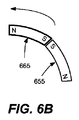
特定の実施形態によると、相反力を最大限まで高めるために、対向する磁石はそれぞれ、係合時に互いに中心を合わせると共に平坦になるように構成する。図6Aおよび図6Bは、円弧形状の静止磁石665および回転磁石655を示す概略図である。図6Aは、時計回り方向に回転する場合のロボットアームの係合の様子を示す図であり、図6Bは反時計回り方向に回転する場合の係合の様子を示す図である。
According to certain embodiments, in order to maximize the reciprocal force, the opposing magnets are each configured to be centered and flat when engaged. 6A and 6B are schematic diagrams showing arc-shaped
上述したように、磁石は、上記では一例としてベアリングを挙げている、可動ハードストップを回転させる力を克服するのに、十分に強力である。利用され得る磁石の例として、ネオジム(ND)磁石が挙げられる。具体例を挙げると、ND35磁石またはND磁石が用いられる。ベアリングの一例として、KA薄型シリーズ(Kaydon(登録商標)社、米国イリノイ州シカゴ)のベアリングが挙げられる。 As mentioned above, the magnet is powerful enough to overcome the force of rotating the movable hard stop, which in the example cited a bearing. An example of a magnet that may be utilized is a neodymium (ND) magnet. As a specific example, an ND35 magnet or an ND magnet is used. An example of a bearing is a bearing of the KA thin series (Kaydon (registered trademark), Chicago, Illinois, USA).
さまざまな実施形態によると、本明細書で記載したロボットアームの回転速度は、最大で150rpm、例えば、120rpm以上である。これを、30rpmでハードストップが係合するとクリック音が発生するハードストップを備えるロボットと比較していただきたい。 According to various embodiments, the rotational speed of the robot arm described herein is up to 150 rpm, such as 120 rpm or more. Compare this to a robot with a hard stop that generates a clicking sound when the hard stop is engaged at 30 rpm.
上述した図面および説明は、回転ハードストップ組立体がどのように構成および実現されるかの例を示したに過ぎない。 The above-described drawings and description merely show examples of how the rotating hard stop assembly is constructed and implemented.
Claims (21)
静止磁石組立体が装着されている静止部材と、
前記静止部材に隣接して設けられており、且つ、回転可能磁石組立体が装着されている回転可能停止部材と
を備え、
前記静止磁石組立体は、1以上の磁石が長手方向に、第1の磁極が前記静止磁石組立体の第1の端部に位置し、第2の磁極が前記静止磁石組立体の第2の端部に位置するように配置されており、
前記回転可能磁石組立体は、1以上の磁石が長手方向に、第3の磁極が前記回転可能磁石組立体の第1の端部に位置し、第4の磁極が前記回転可能磁石組立体の第2の端部に位置するように配置されており、
前記回転可能磁石組立体は、前記静止磁石組立体と係合可能であり、
前記回転可能停止部材は、前記静止部材と係合していない場合には、前記機構と共に回転するように前記機構上に装着されている装置。 A device that restricts rotation in a mechanism that performs θ rotation about the Z axis,
A stationary member on which a stationary magnet assembly is mounted;
A rotatable stop member provided adjacent to the stationary member and mounted with a rotatable magnet assembly;
The stationary magnet assembly has one or more magnets in the longitudinal direction, a first magnetic pole located at a first end of the stationary magnet assembly, and a second magnetic pole located at a second end of the stationary magnet assembly. It is arranged to be located at the end,
The rotatable magnet assembly has one or more magnets in the longitudinal direction, a third magnetic pole located at a first end of the rotatable magnet assembly, and a fourth magnetic pole of the rotatable magnet assembly. Arranged to be located at the second end,
The rotatable magnet assembly is engageable with the stationary magnet assembly;
An apparatus mounted on the mechanism such that the rotatable stop member rotates with the mechanism when not engaged with the stationary member.
第1の回転方向に前記機構および前記回転可能停止部材を回転させる段階と、
選択された回転位置において、前記回転可能停止部材と前記静止部材とを非接触形式で係合させて、前記回転可能停止部材の回転を止めて静止させる段階と、
前記第1の回転方向に前記回転可能停止部材を超えて前記機構を回転させる段階と
を備える方法。 A method of rotating a mechanism that performs a θ rotation about the Z axis, a stationary member on which a stationary magnet assembly is mounted, and a rotatable magnet assembly that is adjacent to the stationary member and that is rotatable. A method using a rotatable stop member that is mounted,
Rotating the mechanism and the rotatable stop member in a first rotational direction;
Engaging the rotatable stop member and the stationary member in a non-contact manner at a selected rotational position, stopping rotation of the rotatable stop member and making it stationary; and
Rotating the mechanism beyond the rotatable stop member in the first rotational direction.
前記第2の回転方向は、前記第1の回転方向の逆方向である請求項16に記載の方法。 Further comprising rotating the mechanism in a second rotational direction;
The method of claim 16, wherein the second direction of rotation is opposite to the first direction of rotation.
複数の取得位置および載置位置と、
a)360度を超えて非連続回転を行うロボットアーム、および、b)磁石回転ハードストップ組立体を有する基板搬送ロボットと
を備えるシステム。 A system for transporting substrates,
A plurality of acquisition positions and placement positions;
a) a robot arm that performs non-continuous rotation beyond 360 degrees, and b) a substrate transfer robot having a magnet rotating hard stop assembly.
Applications Claiming Priority (3)
| Application Number | Priority Date | Filing Date | Title |
|---|---|---|---|
| US12/432,620 US8757345B2 (en) | 2009-04-29 | 2009-04-29 | Magnetic rotational hardstop for robot |
| US12/432,620 | 2009-04-29 | ||
| PCT/US2010/031489 WO2010126726A2 (en) | 2009-04-29 | 2010-04-16 | Magnetic rotational hardstop for robot |
Publications (2)
| Publication Number | Publication Date |
|---|---|
| JP2012525272A true JP2012525272A (en) | 2012-10-22 |
| JP2012525272A5 JP2012525272A5 (en) | 2013-06-13 |
Family
ID=43030463
Family Applications (1)
| Application Number | Title | Priority Date | Filing Date |
|---|---|---|---|
| JP2012508526A Abandoned JP2012525272A (en) | 2009-04-29 | 2010-04-16 | Magnet rotation hard stop for robot |
Country Status (6)
| Country | Link |
|---|---|
| US (1) | US8757345B2 (en) |
| JP (1) | JP2012525272A (en) |
| KR (1) | KR20130026363A (en) |
| CN (1) | CN102458778B (en) |
| TW (1) | TWI577513B (en) |
| WO (1) | WO2010126726A2 (en) |
Families Citing this family (26)
| Publication number | Priority date | Publication date | Assignee | Title |
|---|---|---|---|---|
| US8336419B2 (en) * | 2004-04-08 | 2012-12-25 | Fabworx Solutions, Inc. | Hub assembly for robotic arm having pin spacers |
| US8060252B2 (en) | 2007-11-30 | 2011-11-15 | Novellus Systems, Inc. | High throughput method of in transit wafer position correction in system using multiple robots |
| US9002514B2 (en) | 2007-11-30 | 2015-04-07 | Novellus Systems, Inc. | Wafer position correction with a dual, side-by-side wafer transfer robot |
| CN101774179B (en) * | 2009-01-10 | 2012-09-19 | 鸿富锦精密工业(深圳)有限公司 | Robot connecting shaft |
| JP5818346B2 (en) * | 2011-04-27 | 2015-11-18 | 日本電産サンキョー株式会社 | Rotating body rotation range regulating mechanism and industrial robot |
| CN103085082B (en) * | 2011-11-04 | 2015-10-14 | 鸿富锦精密工业(深圳)有限公司 | Robot arm |
| DE102012208430A1 (en) * | 2012-05-21 | 2013-11-21 | Kuka Roboter Gmbh | Industrial robot with an annular drag stop |
| EP2708332B1 (en) | 2012-09-17 | 2016-11-16 | Eppendorf Ag | Articulated device, micro-manipulator assembly with same and method for use |
| JP5990359B2 (en) * | 2012-10-04 | 2016-09-14 | 平田機工株式会社 | Loading / unloading robot |
| US9833895B2 (en) * | 2012-10-29 | 2017-12-05 | Arizona Board Of Regents On Behalf Of Arizona State University | Coupling system |
| EP3198695A4 (en) | 2014-09-26 | 2018-05-16 | ABB Schweiz AG | A routing unit, a rotary joint and a robot |
| CN105252547B (en) * | 2015-10-21 | 2018-03-09 | 国机智能科技有限公司 | A kind of industrial machine National People's Congress stroke joint position limiter |
| JP6678034B2 (en) * | 2016-01-12 | 2020-04-08 | 本田技研工業株式会社 | Operation control system and operation control method |
| DE112017000578T5 (en) * | 2016-01-30 | 2018-11-08 | Life Robotics Inc. | A robot arm |
| JP6663774B2 (en) * | 2016-03-30 | 2020-03-13 | 東京エレクトロン株式会社 | Substrate transfer method and substrate processing system |
| US9925663B2 (en) * | 2016-07-07 | 2018-03-27 | Universal City Studios Llc | Movable hardstop for a robotic component |
| US10464427B2 (en) | 2016-08-29 | 2019-11-05 | Universal City Studios Llc | Systems and methods for braking or propelling a roaming vehicle |
| CN106272565A (en) * | 2016-09-27 | 2017-01-04 | 昆山穿山甲机器人有限公司 | Robot preventer |
| CN107584496B (en) * | 2017-09-04 | 2020-12-01 | 重庆市臻憬科技开发有限公司 | Magnetic sucker for intelligent restaurant |
| US10796940B2 (en) | 2018-11-05 | 2020-10-06 | Lam Research Corporation | Enhanced automatic wafer centering system and techniques for same |
| WO2020133269A1 (en) * | 2018-12-28 | 2020-07-02 | 深圳配天智能技术研究院有限公司 | Limiting device, mechanical arm, and robot |
| CN111788046B (en) * | 2019-04-12 | 2023-06-06 | 深圳配天智能技术研究院有限公司 | Limiting device, mechanical arm and robot |
| WO2020206685A1 (en) * | 2019-04-12 | 2020-10-15 | 深圳配天智能技术研究院有限公司 | Limiting apparatus, mechanical arm, and robot |
| WO2022061482A1 (en) * | 2020-09-22 | 2022-03-31 | Shanghai Flexiv Robotics Technology Co., Ltd. | Brake apparatus, robot joint and robot including the same |
| JP2022096111A (en) * | 2020-12-17 | 2022-06-29 | セイコーエプソン株式会社 | Robot arm and robot |
| WO2022150157A1 (en) | 2021-01-06 | 2022-07-14 | American Sterilizer Company | Medical device support system including rotational control mechanism |
Family Cites Families (32)
| Publication number | Priority date | Publication date | Assignee | Title |
|---|---|---|---|---|
| US3467973A (en) * | 1967-09-28 | 1969-09-23 | Chris A Minnick | Magnetic spring or shock absorber device |
| JPS6198240A (en) * | 1984-10-18 | 1986-05-16 | 横河メディカルシステム株式会社 | Mechanical stopper apparatus |
| JPS6228194A (en) * | 1985-07-29 | 1987-02-06 | フアナツク株式会社 | Regulator for operating range of industrial robot |
| US4767257A (en) | 1985-12-23 | 1988-08-30 | Mitsubishi Denki Kabushiki Kaisha | Industrial robot |
| JPS63123688A (en) * | 1986-11-13 | 1988-05-27 | フアナツク株式会社 | Turning-shaft waterproof device for industrial robot |
| US5145227A (en) * | 1990-12-31 | 1992-09-08 | The United States Of America As Represented By The Administrator Of The National Aeronautics And Space Administration | Electromagnetic attachment mechanism |
| US5724264A (en) * | 1993-07-16 | 1998-03-03 | Immersion Human Interface Corp. | Method and apparatus for tracking the position and orientation of a stylus and for digitizing a 3-D object |
| US5473961A (en) * | 1993-10-29 | 1995-12-12 | Pepco Water Conservation Products | Control apparatus |
| US5676472A (en) * | 1995-07-10 | 1997-10-14 | Smart Machines | Rotary labyrinth seal |
| US5765444A (en) * | 1995-07-10 | 1998-06-16 | Kensington Laboratories, Inc. | Dual end effector, multiple link robot arm system with corner reacharound and extended reach capabilities |
| US6697748B1 (en) * | 1995-08-07 | 2004-02-24 | Immersion Corporation | Digitizing system and rotary table for determining 3-D geometry of an object |
| US5839322A (en) * | 1996-01-26 | 1998-11-24 | Genmark Automation | Robotic arm rotation controller |
| KR200145221Y1 (en) * | 1996-07-30 | 1999-06-15 | 윤종용 | The stopper of robot arm |
| US6487738B1 (en) * | 2000-03-20 | 2002-12-03 | Offspring, Llc | Constant restoring force support surface |
| JP5259907B2 (en) * | 2000-09-01 | 2013-08-07 | クロッシング オートメーション インコーポレイテッド | Machining tool, method of aligning workpieces, and method of machining workpieces one after another |
| US6601468B2 (en) * | 2000-10-24 | 2003-08-05 | Innovative Robotic Solutions | Drive system for multiple axis robot arm |
| JP2004014660A (en) * | 2002-06-05 | 2004-01-15 | Honda Motor Co Ltd | Actuator |
| US20060043750A1 (en) * | 2004-07-09 | 2006-03-02 | Paul Wirth | End-effectors for handling microfeature workpieces |
| US6854579B2 (en) * | 2003-03-13 | 2005-02-15 | Royal-G Enterprise Co., Ltd. | Rotation angle-adjustable rotating device |
| US20070020080A1 (en) * | 2004-07-09 | 2007-01-25 | Paul Wirth | Transfer devices and methods for handling microfeature workpieces within an environment of a processing machine |
| US7643196B2 (en) * | 2005-12-16 | 2010-01-05 | The Charles Stark Draper Laboratory, Inc. | Systems, methods and devices for actuating a moveable miniature platform |
| JP4940428B2 (en) * | 2006-08-02 | 2012-05-30 | 国立大学法人九州工業大学 | Non-contact magnetic levitation method using magnetic material and non-contact magnetic levitation apparatus using the same |
| CN201007333Y (en) * | 2007-02-02 | 2008-01-16 | 常熟理工学院 | Composite type magnetic floating damping vibration attenuation device |
| CN201080984Y (en) * | 2007-03-30 | 2008-07-02 | 上海市闸北区中小学科技指导站 | Magnetic force shock-absorber |
| CN201068947Y (en) * | 2007-07-07 | 2008-06-04 | 郑长旺 | Magnet shock-absorber |
| CN201078424Y (en) * | 2007-07-21 | 2008-06-25 | 秦永刚 | Magnetic oscillating damper |
| US20090174289A1 (en) * | 2007-12-28 | 2009-07-09 | Adaptivenergy Llc | Magnetic impulse energy harvesting device and method |
| TWM356030U (en) * | 2008-03-04 | 2009-05-01 | Hong-Wei Zhang | Improved structure of magnetic shock absorber |
| CN201206607Y (en) * | 2008-03-27 | 2009-03-11 | 河南大学 | Adjustable magnetic spring |
| CN201246432Y (en) * | 2008-08-06 | 2009-05-27 | 李国兴 | Magnetoelastic shock damper |
| DE102009043404A1 (en) * | 2009-09-29 | 2011-09-22 | Kuka Roboter Gmbh | Industrial robot with a tow stop |
| DE102012208430A1 (en) * | 2012-05-21 | 2013-11-21 | Kuka Roboter Gmbh | Industrial robot with an annular drag stop |
-
2009
- 2009-04-29 US US12/432,620 patent/US8757345B2/en active Active
-
2010
- 2010-04-16 CN CN201080025333.XA patent/CN102458778B/en active Active
- 2010-04-16 KR KR1020117028014A patent/KR20130026363A/en not_active Application Discontinuation
- 2010-04-16 JP JP2012508526A patent/JP2012525272A/en not_active Abandoned
- 2010-04-16 WO PCT/US2010/031489 patent/WO2010126726A2/en active Application Filing
- 2010-04-28 TW TW099113557A patent/TWI577513B/en active
Also Published As
| Publication number | Publication date |
|---|---|
| US8757345B2 (en) | 2014-06-24 |
| TWI577513B (en) | 2017-04-11 |
| CN102458778A (en) | 2012-05-16 |
| WO2010126726A3 (en) | 2011-03-17 |
| US20100278623A1 (en) | 2010-11-04 |
| TW201105471A (en) | 2011-02-16 |
| WO2010126726A2 (en) | 2010-11-04 |
| CN102458778B (en) | 2016-02-03 |
| KR20130026363A (en) | 2013-03-13 |
Similar Documents
| Publication | Publication Date | Title |
|---|---|---|
| JP2012525272A (en) | Magnet rotation hard stop for robot | |
| US11978649B2 (en) | Substrate processing apparatus | |
| KR102371539B1 (en) | Dual robot including spaced upper arms and interleaved wrists and systems and methods including same | |
| US8777547B2 (en) | Systems, apparatus and methods for transporting substrates | |
| KR102153608B1 (en) | Boom drive apparatus, multi-arm robot apparatus, electronic device processing systems, and methods for transporting substrates in electronic device manufacturing systems | |
| JP2012525272A5 (en) | ||
| JP6550391B2 (en) | Robotic apparatus, drive assembly and method for transferring a substrate in electronic device manufacturing | |
| TWI413200B (en) | Workpiece transfer assembly and a method for manioulating the workpiece | |
| JPH03136779A (en) | Magnetically connected two-shaft type robot | |
| JP2012514544A5 (en) | ||
| JP2010258480A (en) | Aligner apparatus | |
| JPWO2007094517A1 (en) | Robot hand | |
| CN110712195A (en) | Transfer robot and robot system | |
| KR20150073876A (en) | Robot with integrated aligner | |
| US9776321B2 (en) | Posture holding device for holding part | |
| KR20070014277A (en) | Equipment for manufacturing semiconductor device | |
| CN105835033A (en) | Robot | |
| US20130213171A1 (en) | Substrate transfer apparatus | |
| US7296962B2 (en) | Split assembly robotic arm | |
| US20230085667A1 (en) | Substrate transfer systems and methods of use thereof | |
| KR102552870B1 (en) | Wafer transfer robot apparatus based on direct drive motor | |
| WO2023143699A1 (en) | Arrangement for limiting rotation, and robot | |
| KR100699154B1 (en) | Standard mechanical interface apparatus | |
| JPH04281377A (en) | Slide device | |
| KR20120137662A (en) | Traveling vacuum robot |
Legal Events
| Date | Code | Title | Description |
|---|---|---|---|
| A521 | Written amendment |
Free format text: JAPANESE INTERMEDIATE CODE: A523 Effective date: 20130415 |
|
| A621 | Written request for application examination |
Free format text: JAPANESE INTERMEDIATE CODE: A621 Effective date: 20130415 |
|
| A762 | Written abandonment of application |
Free format text: JAPANESE INTERMEDIATE CODE: A762 Effective date: 20130701 |