JP2012523350A - Reinforcement, baffle and sealing method - Google Patents
Reinforcement, baffle and sealing method Download PDFInfo
- Publication number
- JP2012523350A JP2012523350A JP2012504724A JP2012504724A JP2012523350A JP 2012523350 A JP2012523350 A JP 2012523350A JP 2012504724 A JP2012504724 A JP 2012504724A JP 2012504724 A JP2012504724 A JP 2012504724A JP 2012523350 A JP2012523350 A JP 2012523350A
- Authority
- JP
- Japan
- Prior art keywords
- materials
- holes
- hole
- sealing
- length
- Prior art date
- Legal status (The legal status is an assumption and is not a legal conclusion. Google has not performed a legal analysis and makes no representation as to the accuracy of the status listed.)
- Ceased
Links
Images


Classifications
-
- B—PERFORMING OPERATIONS; TRANSPORTING
- B62—LAND VEHICLES FOR TRAVELLING OTHERWISE THAN ON RAILS
- B62D—MOTOR VEHICLES; TRAILERS
- B62D65/00—Designing, manufacturing, e.g. assembling, facilitating disassembly, or structurally modifying motor vehicles or trailers, not otherwise provided for
- B62D65/02—Joining sub-units or components to, or positioning sub-units or components with respect to, body shell or other sub-units or components
-
- B—PERFORMING OPERATIONS; TRANSPORTING
- B62—LAND VEHICLES FOR TRAVELLING OTHERWISE THAN ON RAILS
- B62D—MOTOR VEHICLES; TRAILERS
- B62D29/00—Superstructures, understructures, or sub-units thereof, characterised by the material thereof
- B62D29/001—Superstructures, understructures, or sub-units thereof, characterised by the material thereof characterised by combining metal and synthetic material
- B62D29/002—Superstructures, understructures, or sub-units thereof, characterised by the material thereof characterised by combining metal and synthetic material a foamable synthetic material or metal being added in situ
-
- B—PERFORMING OPERATIONS; TRANSPORTING
- B21—MECHANICAL METAL-WORKING WITHOUT ESSENTIALLY REMOVING MATERIAL; PUNCHING METAL
- B21D—WORKING OR PROCESSING OF SHEET METAL OR METAL TUBES, RODS OR PROFILES WITHOUT ESSENTIALLY REMOVING MATERIAL; PUNCHING METAL
- B21D53/00—Making other particular articles
- B21D53/88—Making other particular articles other parts for vehicles, e.g. cowlings, mudguards
-
- Y—GENERAL TAGGING OF NEW TECHNOLOGICAL DEVELOPMENTS; GENERAL TAGGING OF CROSS-SECTIONAL TECHNOLOGIES SPANNING OVER SEVERAL SECTIONS OF THE IPC; TECHNICAL SUBJECTS COVERED BY FORMER USPC CROSS-REFERENCE ART COLLECTIONS [XRACs] AND DIGESTS
- Y10—TECHNICAL SUBJECTS COVERED BY FORMER USPC
- Y10T—TECHNICAL SUBJECTS COVERED BY FORMER US CLASSIFICATION
- Y10T156/00—Adhesive bonding and miscellaneous chemical manufacture
- Y10T156/10—Methods of surface bonding and/or assembly therefor
- Y10T156/1002—Methods of surface bonding and/or assembly therefor with permanent bending or reshaping or surface deformation of self sustaining lamina
- Y10T156/1003—Methods of surface bonding and/or assembly therefor with permanent bending or reshaping or surface deformation of self sustaining lamina by separating laminae between spaced secured areas [e.g., honeycomb expanding]
-
- Y—GENERAL TAGGING OF NEW TECHNOLOGICAL DEVELOPMENTS; GENERAL TAGGING OF CROSS-SECTIONAL TECHNOLOGIES SPANNING OVER SEVERAL SECTIONS OF THE IPC; TECHNICAL SUBJECTS COVERED BY FORMER USPC CROSS-REFERENCE ART COLLECTIONS [XRACs] AND DIGESTS
- Y10—TECHNICAL SUBJECTS COVERED BY FORMER USPC
- Y10T—TECHNICAL SUBJECTS COVERED BY FORMER US CLASSIFICATION
- Y10T156/00—Adhesive bonding and miscellaneous chemical manufacture
- Y10T156/10—Methods of surface bonding and/or assembly therefor
- Y10T156/1002—Methods of surface bonding and/or assembly therefor with permanent bending or reshaping or surface deformation of self sustaining lamina
- Y10T156/1028—Methods of surface bonding and/or assembly therefor with permanent bending or reshaping or surface deformation of self sustaining lamina by bending, drawing or stretch forming sheet to assume shape of configured lamina while in contact therewith
-
- Y—GENERAL TAGGING OF NEW TECHNOLOGICAL DEVELOPMENTS; GENERAL TAGGING OF CROSS-SECTIONAL TECHNOLOGIES SPANNING OVER SEVERAL SECTIONS OF THE IPC; TECHNICAL SUBJECTS COVERED BY FORMER USPC CROSS-REFERENCE ART COLLECTIONS [XRACs] AND DIGESTS
- Y10—TECHNICAL SUBJECTS COVERED BY FORMER USPC
- Y10T—TECHNICAL SUBJECTS COVERED BY FORMER US CLASSIFICATION
- Y10T29/00—Metal working
- Y10T29/18—Expanded metal making
- Y10T29/185—Expanded metal making by use of reciprocating perforator
-
- Y—GENERAL TAGGING OF NEW TECHNOLOGICAL DEVELOPMENTS; GENERAL TAGGING OF CROSS-SECTIONAL TECHNOLOGIES SPANNING OVER SEVERAL SECTIONS OF THE IPC; TECHNICAL SUBJECTS COVERED BY FORMER USPC CROSS-REFERENCE ART COLLECTIONS [XRACs] AND DIGESTS
- Y10—TECHNICAL SUBJECTS COVERED BY FORMER USPC
- Y10T—TECHNICAL SUBJECTS COVERED BY FORMER US CLASSIFICATION
- Y10T29/00—Metal working
- Y10T29/49—Method of mechanical manufacture
- Y10T29/496—Multiperforated metal article making
-
- Y—GENERAL TAGGING OF NEW TECHNOLOGICAL DEVELOPMENTS; GENERAL TAGGING OF CROSS-SECTIONAL TECHNOLOGIES SPANNING OVER SEVERAL SECTIONS OF THE IPC; TECHNICAL SUBJECTS COVERED BY FORMER USPC CROSS-REFERENCE ART COLLECTIONS [XRACs] AND DIGESTS
- Y10—TECHNICAL SUBJECTS COVERED BY FORMER USPC
- Y10T—TECHNICAL SUBJECTS COVERED BY FORMER US CLASSIFICATION
- Y10T29/00—Metal working
- Y10T29/49—Method of mechanical manufacture
- Y10T29/49616—Structural member making
- Y10T29/49622—Vehicular structural member making
-
- Y—GENERAL TAGGING OF NEW TECHNOLOGICAL DEVELOPMENTS; GENERAL TAGGING OF CROSS-SECTIONAL TECHNOLOGIES SPANNING OVER SEVERAL SECTIONS OF THE IPC; TECHNICAL SUBJECTS COVERED BY FORMER USPC CROSS-REFERENCE ART COLLECTIONS [XRACs] AND DIGESTS
- Y10—TECHNICAL SUBJECTS COVERED BY FORMER USPC
- Y10T—TECHNICAL SUBJECTS COVERED BY FORMER US CLASSIFICATION
- Y10T29/00—Metal working
- Y10T29/53—Means to assemble or disassemble
Landscapes
- Engineering & Computer Science (AREA)
- Mechanical Engineering (AREA)
- Chemical & Material Sciences (AREA)
- Combustion & Propulsion (AREA)
- Transportation (AREA)
- Architecture (AREA)
- Structural Engineering (AREA)
- Manufacturing & Machinery (AREA)
- Body Structure For Vehicles (AREA)
Abstract
車両構造体を補強し、バッフルし又は封止する方法であって、穴が形成された材料(10)を用意してこの材料を引き伸ばして特定の車両構造体に合わせるステップを有する、方法。 A method of reinforcing, baffling or sealing a vehicle structure, comprising the step of providing a holed material (10) and stretching the material to match a particular vehicle structure.
Description
本発明は、一般に、1つ又は2つ以上の材料が伸張することができるようにする穴がこのような1つ又は2つ以上の材料に沿って形成されているこのような1つ又は2つ以上の材料から成るバッフル(baffling)、封止(sealing )又は補強(reinforcement )用の部材に関する。 The present invention generally relates to such one or two holes being formed along such one or more materials that allow one or more materials to stretch. It relates to a baffling, sealing or reinforcement member made of one or more materials.
〔関連出願の説明〕
本願は、2009年4月8日に出願された米国特許出願第12/420,406号の出願日に係る権益主張出願であり、この米国特許出願を参照により引用し、その記載内容全体を本明細書の一部とする。
[Description of related applications]
The present application is an application for claiming the interest of the filing date of US patent application Ser. No. 12 / 420,406 filed on Apr. 8, 2009, which is incorporated herein by reference. Part of the description.
輸送業界は、機能を向上させると同時に重量及びコストを減少させることができるバッフル(流れ調節)、封止及び補強方法を必要とし続けている。 The transportation industry continues to require baffles, flow control, sealing and reinforcement methods that can improve functionality while reducing weight and cost.
多くの場合、機能の向上に伴って重量が増大すると共に費用が増加する。例えば、硬質材料の強度の向上には、追加の材料を必要とする場合が多く、それにより、費用と重量の両方が増大する。変形例として、強度が向上した大抵の軽量材料は、費用の増大を伴う場合が多い。全重量を減少させようとして、バッフル、封止及び補強目的で膨張性(expandable)材料が用いられる場合が多い。多くの膨張性材料には多くの追加の問題がある。膨張特性が向上した材料は、制御が困難な場合が多く、通常、費用増大が伴う。さらに、多くの場合、膨張性材料の強度が増大すると、重量も増大する。バッフル、封止及び補強用途向きに接着材料も又一般に使用されているが、このような接着材料も又、接着性の向上と関連した費用の増大傾向を示している。本発明は、バッフル、封止及び補強のための能力を向上させる一方で、重量を減少させると共に費用を減少させる材料の要望に取り組む。 In many cases, the functionality increases and the weight increases and the cost increases. For example, increasing the strength of hard materials often requires additional materials, thereby increasing both cost and weight. As a variant, most lightweight materials with improved strength often involve increased costs. In order to reduce the overall weight, expandable materials are often used for baffle, sealing and reinforcement purposes. Many expandable materials have many additional problems. Materials with improved expansion properties are often difficult to control and usually involve increased costs. Furthermore, in many cases, the weight increases as the strength of the expandable material increases. Adhesive materials are also commonly used for baffle, sealing and reinforcement applications, but such adhesive materials also show an increasing cost trend associated with improved adhesion. The present invention addresses the need for materials that reduce weight and cost while improving the ability for baffles, sealing and reinforcement.
第1の観点では、本発明は、車両構造体を補強し、バッフルし又は封止する方法に関し、この方法は、車両構造体を補強し、バッフルし又は封止する1つ又は2つ以上の材料を用意するステップを有し、1つ又は2つ以上の材料は、水平軸線、少なくとも1つの末端縁及び初期長さを有する。次に、1つ又は2つ以上の材料にこのような材料に沿って繰り返しパターンをなして穴を形成するのが良く、穴の形成によっては材料が除去されず、無駄が最小限に抑えられるようにする。次に、このような材料を初期長さの少なくとも1.3倍の配置長さに引き伸ばすのが良く、配置長さは、補強、バッフル、封止又はこれらの任意の組み合わせを必要とする場所の長さに一致する。次に、引き伸ばした材料を補強、バッフル、封止又はこれらの任意の組み合わせを必要とする場所に貼り付けて材料の貼り付け全量が材料に穴が設けられていない場合に必要な貼り付け全量よりも少ないようにするのが良い。穴は、水平軸線に垂直に形成されるのが良い。形成された穴は、交互に位置し、一つおきの穴が1つ又は2つ以上の材料を少なくとも1つの末端縁のところで切り離し、残りの隣りの穴が前記1つ又は2つ以上の材料を水平軸線のところで切り離すようにするのが良い。 In a first aspect, the present invention relates to a method for reinforcing, baffling or sealing a vehicle structure, the method comprising reinforcing one or more of the vehicle structure reinforcing, baffling or sealing. Providing a material, wherein the one or more materials have a horizontal axis, at least one end edge and an initial length; Next, one or more materials may be repetitively patterned to form holes along such materials, which does not remove material and minimizes waste. Like that. The material can then be stretched to a deployment length that is at least 1.3 times the initial length, where the deployment length is where the reinforcement, baffle, sealing, or any combination thereof is required. Match the length. Next, apply the stretched material to a place where reinforcement, baffle, sealing, or any combination thereof is required, and if the total amount of the material is not provided with a hole in the material, It is good to make it less. The hole may be formed perpendicular to the horizontal axis. The holes formed are alternating, every other hole cuts one or more materials at at least one end edge, and the remaining adjacent holes are said one or more materials. Should be separated at the horizontal axis.
本明細書において開示する方法は、以下のうちの1つ又は任意の組み合わせ(これには限定されない)を含む多くの利益及び利点を提供する。車両構造体を効果的に封止し又は補強するのに必要な材料の量を減少させることができる。膨張性材料の場合、膨張方向及び膨張量の制御性を向上させることができる。封止、バッフル又は補強は、材料の配置場所及び量を容易に変化させることができるのでカスタマイズできる。 The methods disclosed herein provide many benefits and advantages, including but not limited to one or any combination of the following. The amount of material required to effectively seal or reinforce the vehicle structure can be reduced. In the case of an expandable material, the controllability of the expansion direction and the expansion amount can be improved. The seal, baffle or reinforcement can be customized because the location and amount of material can be easily changed.
本発明は、車両構造体のバッフル、封止又は補強のための1つ又は2つ以上の材料のカスタマイゼーションを可能にする。本明細書において開示する実施形態は、穴を材料に形成する方法に関し、材料を車両構造体内に正確に嵌め込むことができるよう所望の長さ、形状、曲率又はこれらの任意の組み合わせに合わせて調節できるようにする。本明細書において開示する材料は、好ましい膨張特性が得られるよう一段とカスタマイズ可能である。 The present invention allows customization of one or more materials for baffle, sealing or reinforcement of the vehicle structure. Embodiments disclosed herein relate to a method of forming a hole in a material, tailored to a desired length, shape, curvature, or any combination thereof so that the material can be accurately fitted into a vehicle structure. Make it adjustable. The materials disclosed herein can be further customized to provide favorable expansion properties.
図1A及び図1Bは、穴11の形成前(図1A)及び形成後(図1B)の膨張性材料10を示している。穴11aが膨張性材料10を両方の末端縁12から切り離す2つのスリット又は切れ目として示され、膨張性材料は、2つのスリット相互間で水平軸線13のところに連結状態のままになっている。穴11bが膨張性材料を水平軸線13のところで切り離す1つのスリットとして示されており、膨張性材料は、末端縁12のところで連結状態のままである。穴11a,11bは、膨張性材料の長さに沿って交互に位置した状態で示されている。穴11a,11bは、膨張性材料に設けられたスリットとして示されており、したがって、切断の際に材料が除去されず、それにより無駄が最小限に抑えられる。穴により、材料を材料の元の長さ(例えば、材料への穴の形成前の材料の長さ)の少なくとも1.2倍まで引き伸ばすことができる限り、穴をバッフル、封止又は補強のための材料に沿って任意のパターンで且つ任意の配設場所に形成することができる。スリットは、最小限の引き伸ばしが起こるよう小さく切断されても良く、或いは、スリットは、材料のほんの僅かな量が連結状態のままであり、それにより最大の引き伸ばしを可能にするよう大きくても良い。スリットは、所要の引き伸ばし量に従って任意のサイズに形成可能である。穴は、図1Bに示されているように互いに密接して形成されるのが良い。穴は又、各穴相互間に空間の所定の量が存在する状態で形成可能であり、したがって、或る特定の量の非切断材料が各穴相互間に位置したままである。穴は、繰り返しパターンで形成可能であり又は特定の組織化がなされないでランダムな配設場所に形成可能である。
1A and 1B show the
形成される穴のサイズは、一般に、切断されるべき材料のサイズで決まる場合がある。穴のサイズに言及する際、穴は、材料に設けられたスリットとして形成されるのが良く、したがって、事実上除去される材料はなく、穴のサイズは、材料に形成されたスリットの長さであるといえる。形成される穴は、一般に、少なくとも約10mmであるのが良い。形成される穴は、約150mm以下であるのが良い。形成される穴のサイズは、少なくとも約15mmであるのが良い。形成される穴のサイズは、約30mm以下であるのが良い。しかしながら、材料が特に大きい(例えば、高さ(h)が約200mm以上)場合又は特に小さい(例えば、高さ(h)が約40mm以下である)場合、穴は、開始材料の相対的高さに従って大きくても良く小さくても良い場合がある。 The size of the hole formed may generally depend on the size of the material to be cut. When referring to the size of a hole, the hole may be formed as a slit provided in the material, and therefore there is virtually no material removed, and the size of the hole is the length of the slit formed in the material. You can say that. The hole formed is generally at least about 10 mm. The hole formed may be about 150 mm or less. The size of the hole formed may be at least about 15 mm. The size of the hole formed may be about 30 mm or less. However, if the material is particularly large (eg, the height (h) is greater than or equal to about 200 mm) or is particularly small (eg, the height (h) is less than or equal to about 40 mm), the hole is a relative height of the starting material. Depending on the case, it may be larger or smaller.
穴を形成した後、材料をバッフル、封止又は補強を必要とする任意の場所で任意の車両構造体内に且つ/或いはこれと接触関係をなして配置されるのが良い。図2Aは、図1Aに示されている膨張性材料10をキャリヤ21を備えた車両構造体20に貼り付けられた状態で示している。図示の膨張性材料は、キャリヤの僅かの部分しか覆っていない。しかしながら、図2Bに示されているように、図1Bの膨張性材料は、引き伸ばされて車両構造体20及びキャリヤ21に貼り付け可能である。穴11を備えた膨張性材料は、キャリヤ11の全長にわたって伸びることができる。図1A及び図1Bに示された開始膨張性材料10の量は、同一であるが、形成された穴11は、キャリヤ21の被覆範囲を広げることができる。
After forming the hole, the material may be placed in and / or in contact with any vehicle structure anywhere that requires baffle, sealing or reinforcement. FIG. 2A shows the
車両構造体中への且つ/或いはこれと接触関係をなす膨張性材料10の貼り付け後、膨張性材料は、所定の1組の条件により膨張可能である。例えば、或る特定のレベルの熱への暴露により、膨張性材料は、膨張することができる。図3Aは、図1A及び図2Aで形成穴が示されていない膨張性材料10の膨張特性を示している。図3Bは、図1B及び図2Bに示されている形成穴11を備えた膨張性材料10の膨張特性を示している。図3Aに示された膨張性材料10の膨張高さ(eh)は、膨張性材料10の長さに沿って一様ではない。図3Bに示されている膨張性材料10の膨張高さ(eh)は、膨張性材料10の長さに沿って比較的一様である。膨張高さが一様であることにより、補強、バッフル及び封止効果を向上させることができ、これに対し、膨張高さが一様ではない場合、その結果として弱いスポット及び/又は不連続封止状態が生じる場合がある。
After application of the
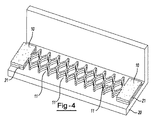
キャリヤ21は、例えば図4に示されているように形成穴を更に有するのが良い。キャリヤ材料の形成穴11は、図4に示されているように膨張性材料10のパターンとほぼ同じであるのが良い。変形例として、キャリヤ材料の形成穴は、膨張性材料10に形成されたパターンとは異なるパターンで切断形成されても良い。別の実施形態では、形成穴11は、キャリヤ材料21に形成されるのが良く、キャリヤ材料は、例えば図5に示されているように膨張性材料を用いないで補強を行なうよう使用できる。
The
バッフル、封止及び補強に用いられる材料は、材料が特定の車両キャビティの形状に合うよう特定のパターンで形成された穴を有するのが良い。例えば図6に示されているように、膨張性材料10は、材料を車両キャビティの輪郭形状に従って2つの互いに逆の方向に引き伸ばすことができるよう形成された穴を有するのが良い。さらに、膨張性材料は、膨張性材料の膨張高さの増大を必要とする場合のある車両キャビティ領域を考慮に入れて穴が設けられていない部分30を有するのが良い。
The material used for baffle, sealing and reinforcement may have holes formed in a specific pattern so that the material matches the shape of a specific vehicle cavity. For example, as shown in FIG. 6, the
穴は又、材料を丸くなった表面沿いに合うように引き伸ばすと共に湾曲することができるよう形成可能である。例えば図7に示されているように、膨張性材料10は、小さなスリットが材料の頂部40に形成され、大きなスリットが材料の底部41に形成されるよう切断されるのが良い。これにより、膨張性材料10を車両構造体内で湾曲した表面42に沿って配置することができ、他方、材料は、表面に面一をなして敷かれ、それにより表面周りに同じ被覆状態を維持することができる。
The holes can also be formed so that the material can be stretched and curved to fit along the rounded surface. For example, as shown in FIG. 7, the
本発明の形成穴は又、締結具及び/又は溶接スポットの空間を提供する。好ましくは、材料を車両構造体に貼り付けることができ、追加の部品又は材料を締結具で取り付けることができ、締結具は、形成穴を介して露出される。さらに、形成穴により、溶接部プロセスを形成穴を介して露出状態にある車両構造体の領域に対して実施することができる。バッフル、封止及び補強のための既存の材料を用いる場合、材料を車両構造体にいったん貼り付けると、下に位置する構造体への接近は、材料が中実であるためにもはや実現可能ではない。本発明の形成穴は又、材料の貼り付け後においても下に位置する車両構造体への接近を可能にすることができる。 The forming holes of the present invention also provide a space for fasteners and / or welding spots. Preferably, the material can be affixed to the vehicle structure and additional parts or materials can be attached with fasteners, which are exposed through the formation holes. In addition, the formation hole allows the weld process to be performed on a region of the vehicle structure that is exposed through the formation hole. When using existing materials for baffles, sealing and reinforcement, once the material is applied to the vehicle structure, access to the underlying structure is no longer feasible because the material is solid. Absent. The formation holes of the present invention can also allow access to the underlying vehicle structure even after application of the material.
穴は、打抜き法を用いて本発明の材料に形成できる。穴は又、ロータリーカット可能である。穴は、プレス打抜き可能であり又はレーザ若しくは水ジェットを用いて切断形成可能である。変形例として、穴を材料中に成形しても良い。 Holes can be formed in the material of the present invention using a stamping process. The hole can also be rotary cut. The holes can be stamped or cut using a laser or water jet. As a variant, holes may be formed in the material.
バッフル、封止又は補強のための材料は、材料を車両構造体内に且つ/或いはこれと接触状態に保つ手段を有するのが良い。この手段としては、締結具、例えばツリーファスナ(tree-fastener)又はねじ締結具が挙げられる。締結具は又、これがバッフル、封止又は補強のための材料を構造体に固定することができる限り、種々の形状で且つ種々の形態で提供できる。好ましくは、締結具は、多数の層又は多くの種類の材料を構造体に固定することができる。適当な締結具の例としては、機械的締結具、クリップ、スナップ嵌め具、ねじ、フック又はこれらの組み合わせ等が挙げられる。車両構造体への取り付けのため、形成穴は、材料を定位置に保持するために車両構造体に設けられたタブ周りに嵌まるよう切断形成されても良い。さらに、1つ又は2つ以上の締結具をバッフル、封止又は補強のための材料と一体に単一の材料で形成されても良く、或いは、異なる材料で形成してキャリヤに取り外し可能に取り付けられても良い。 The material for baffle, sealing or reinforcement may have means for keeping the material in and / or in contact with the vehicle structure. This means includes fasteners such as tree-fasteners or screw fasteners. The fasteners can also be provided in various shapes and configurations as long as it can secure the material for baffle, sealing or reinforcement to the structure. Preferably, the fastener can secure multiple layers or many types of materials to the structure. Examples of suitable fasteners include mechanical fasteners, clips, snap fits, screws, hooks or combinations thereof. For attachment to the vehicle structure, the formation hole may be cut to fit around a tab provided in the vehicle structure to hold the material in place. Further, one or more fasteners may be formed of a single material integrally with the material for baffle, sealing or reinforcement, or may be formed of different materials and removably attached to the carrier. May be.
締結具は、バッフル、封止又は補強のための材料を車両構造体に取り付けることができる(例えば、接着することができる又は磁気的に固定することができる)磁性材料又は接着材料として提供されても良い。磁気材料又は接着材料は、キャリヤ材料又は膨張性材料と所々に散在する状態で配置するのが良い。変形例として、磁気材料又は接着材料をキャリヤ材料及び/又は膨張性材料に被着させても良く又はこれとは違ったやり方でキャリヤ及び/又は膨張性材料に連結しても良い。 The fastener is provided as a magnetic or adhesive material that can attach a material for baffle, sealing or reinforcement to the vehicle structure (eg, can be glued or magnetically secured). Also good. The magnetic material or adhesive material may be arranged in a scattered manner with the carrier material or the expandable material. Alternatively, a magnetic material or adhesive material may be applied to the carrier material and / or expandable material, or may be coupled to the carrier and / or expandable material in a different manner.
バッフル、封止又は補強のための材料は、種々の材料、例えばポリマー、エラストマー、繊維材料(例えば、布又は織物)、熱可塑性樹脂、プラスチック、ナイロン又はこれらの組み合わせ等で形成できる。材料は又、発泡性を備えた熱活性化材料で形成された膨張性材料であっても良い。材料は、一般に、触ってみて乾いていても良く又は粘着性があっても良く、このような材料は、任意形式の所望のパターン、配置状態又は厚さの状態に形成可能であるが、好ましくは、実質的に一様な厚さのものである。他の熱活性材料が膨張性材料として可能であるが、好ましい熱活性化材料は、発泡性ポリマー又はプラスチックであり、好ましくは、発泡性の材料である。特に好ましい材料は、アクリレート、アセテート、エラストマー又はこれらの組み合わせ等のうちの1つ又は2つ以上を含むポリマー配合を有する発泡性の比較的高いフォームである。例えば、フォームは、EVA/ゴムを主成分とする材料であるのが良く、このような材料としては、アルファ‐オレフィンを備えるのが良いエチレンコポリマー又はターポリマーが挙げられる。コポリマー又はターポリマーとして、ポリマーは、2つ又は3つ以上の互いに異なるポリマー、即ち、互いに類似した分子を結合することができる高い化学反応性を備えた小さな分子で構成される。好ましい材料は、米国特許第7,199,165号明細書及び米国特許出願公開第2007/0117874号明細書に開示されている。 The material for baffle, sealing or reinforcement can be formed from various materials such as polymers, elastomers, fiber materials (eg cloth or fabric), thermoplastics, plastics, nylon or combinations thereof. The material may also be an expandable material formed of a heat activated material with foamability. The materials may generally be dry to the touch or may be tacky, and such materials can be formed into any type of desired pattern, arrangement or thickness, but preferably Are of substantially uniform thickness. The preferred thermally activated material is a foamable polymer or plastic, preferably a foamable material, although other thermally active materials are possible as the expandable material. A particularly preferred material is a relatively highly foamable foam having a polymer formulation that includes one or more of acrylates, acetates, elastomers, or combinations thereof. For example, the foam may be a material based on EVA / rubber, such materials including ethylene copolymers or terpolymers that may comprise alpha-olefins. As a copolymer or terpolymer, the polymer is composed of two or more different polymers, i.e., small molecules with high chemical reactivity that can bind molecules similar to each other. Preferred materials are disclosed in U.S. Patent No. 7,199,165 and U.S. Patent Application Publication No. 2007/0117874.
多くのバッフル又は封止フォームが当該技術分野において知られており、このようなフォームは又、上述のフォームを製造するために使用できる。代表的なフォームとしては、適当な成分(代表的には発泡剤及び硬化剤)と化合する際、熱が加えられ又は特定の周囲条件が発生したときに信頼性があり且つ予測可能な仕方で膨張又は発泡すると共に硬化するポリマー基剤、例えばエチレン系ポリマーが挙げられる。熱活性化材料又は熱硬化材料に関する化学的見地から、構造用フォームは、通常、硬化前に流動性熱可塑性材料として当初処理される。このような材料は、代表的には、硬化時に架橋し、それにより材料は、それ以上流動することができなくなる。 Many baffles or sealed foams are known in the art and such foams can also be used to produce the foams described above. Typical foams are in a reliable and predictable manner when heat is applied or certain ambient conditions occur when combined with the appropriate ingredients (typically blowing and curing agents). Examples include polymer bases that expand and foam and cure, such as ethylene-based polymers. From a chemical standpoint for heat activated or thermoset materials, structural foams are usually initially treated as flowable thermoplastic materials prior to curing. Such materials typically crosslink when cured, thereby preventing the material from flowing any further.
膨張性材料を作るための好ましい素材を開示したが、膨張性材料を他の素材で形成することができる。ただし、選択した素材が周囲条件(例えば、水分、圧力、時間等)によって熱活性化され又は違ったやり方で活性化され、そして選択された用途に特有の条件下で予測可能に且つ信頼性のある仕方で硬化することを条件とする。このような素材の1つは、米国特許第6,131,897号明細書に開示されたエポキシ系樹脂であり、この米国特許を参照により引用し、その教示内容を本明細書の一部とする。考えられる他の幾つかの材料としては、ポリオレフィン材料、少なくとも1つのモノマータイプを備えたコポリマー及びターポリマー、アルファ‐オレフィン、フェノール/ホルムアルデヒド材料、フェノキシ材料及びガラス転移温度が高いポリウレタン材料が挙げられるが、これらには限定されない。米国特許第5,766,719号明細書、同第5,755,486号明細書、同第5,575,526号明細書及び同第5,932,680号明細書に開示されている追加の材料も又使用できる。なお、これら米国特許も又参照により引用し、これらの開示内容を本明細書の一部とする。 Although preferred materials for making the expandable material have been disclosed, the expandable material can be formed of other materials. However, the selected material is thermally activated or otherwise activated by ambient conditions (eg, moisture, pressure, time, etc.) and is predictable and reliable under conditions specific to the selected application. Subject to curing in some way. One such material is the epoxy-based resin disclosed in US Pat. No. 6,131,897, which is incorporated herein by reference and the teachings of which are incorporated herein by reference. To do. Some other possible materials include polyolefin materials, copolymers and terpolymers with at least one monomer type, alpha-olefins, phenol / formaldehyde materials, phenoxy materials and polyurethane materials with high glass transition temperatures. However, it is not limited to these. Additional disclosures disclosed in U.S. Pat. Nos. 5,766,719, 5,755,486, 5,575,526 and 5,932,680 These materials can also be used. It should be noted that these US patents are also incorporated by reference, the disclosures of which are incorporated herein.
バッフル、封止及び補強のための材料は、接着剤を更に含むのが良い。接着材料は、代表的には、活性化可能材料であり、このことは、接着材料を活性化させると、これが溶融し、くっつき、発泡し、膨張し、硬化し、熱硬化し、或いはこれらの任意の組み合わせを行なうことができるということを意味しているが、このことが必ずしも必要であるというわけではない。このような活性化は、代表的には、接着材料を例えば熱、放射線、水分等の条件に暴露することによって行なわれる。また、接着材料を単独で用いても良く、或いは、補強材、バッフル又はシールを形成するためにキャリヤ材料、膨張性材料、追加の膨張性材料又はこれらの任意の組み合わせと関連して用いても良いことが想定される。 The material for baffle, sealing and reinforcement may further comprise an adhesive. The adhesive material is typically an activatable material, which, when activated, melts, sticks, foams, expands, cures, thermosets, or these This means that any combination can be made, but this is not always necessary. Such activation is typically performed by exposing the adhesive material to conditions such as heat, radiation, moisture, and the like. Also, the adhesive material may be used alone or in conjunction with a carrier material, an expandable material, an additional expandable material, or any combination thereof to form a stiffener, baffle or seal. Expected to be good.
接着材料は、エポキシ、アクリレート、アセテート、エチレンポリマー(例えば、コポリマー)、エラストマー、これらの組み合わせ等のうちの1つ又は2つ以上を含み又はこれを基剤とするポリマー配合を有するのが良い。接着材料は、封止及び/又は構造的補強及び/又は接着を含む用途に特に有用である場合がある。構造的用途に関し、接着材料の膨張は、膨張が少しでも存在する場合であっても典型的には僅かである。 The adhesive material may have a polymer formulation that includes or is based on one or more of epoxies, acrylates, acetates, ethylene polymers (eg, copolymers), elastomers, combinations thereof, and the like. The adhesive material may be particularly useful for applications involving sealing and / or structural reinforcement and / or adhesion. For structural applications, the expansion of the adhesive material is typically negligible even if any expansion is present.
接着材料は、所定の圧力条件が加えられたときに活性化可能である感圧材料であるのが良い。特定の有用な一材料は、米国特許出願公開第2005/0241756号明細書に記載されている。 The adhesive material may be a pressure sensitive material that can be activated when a predetermined pressure condition is applied. One particular useful material is described in U.S. Patent Application Publication No. 2005/0241756.
接着材料又は任意他の膨張性材料が熱活性化材料である用途では、材料の選択及び配合に関する重要な検討事項は、材料の硬化温度及び膨張可能である場合には膨張温度である。代表的には、このような材料は、この材料が自動車構造体と一緒に高い温度で又は高い印加エネルギーレベルで、例えば塗装(例えば、e‐コート、塗料又はクリアコート)硬化ステップの際に処理される場合、例えば自動車組み立て工場で遭遇する高い処理温度においては反応性になる(硬化、膨張又はこれら両方を行なう)。自動車組み立て作業で遭遇する温度は、車体整備用途(例えば、e‐コート)では約148.89℃から204.44℃まで(約300°Fから400°Fまで)の範囲にある場合があり、塗装用途では、通常約93.33℃(約200°F)又はこれよりも僅かに高い(例えば、120℃〜150℃)である場合がある。 In applications where the adhesive material or any other expandable material is a heat activated material, an important consideration regarding material selection and formulation is the curing temperature of the material and the expansion temperature if it is expandable. Typically, such materials are processed during a curing step, such as a paint (eg, e-coat, paint or clear coat), such as at a high temperature or high applied energy level with the automobile structure. When done, it becomes reactive (curing, expanding, or both) at the high processing temperatures encountered, for example, in automobile assembly plants. The temperatures encountered in automobile assembly operations may range from about 148.89 ° C. to 204.44 ° C. (about 300 ° F. to 400 ° F.) for car body maintenance applications (eg, e-coat), For paint applications, it may typically be about 93.33 ° C. (about 200 ° F.) or slightly higher (eg, 120 ° C. to 150 ° C.).
材料は、例えば米国特許出願公開第2004/0076831号明細書及び同第2005/0260399号明細書に開示されているフィルム層を更に含むのが良い。フィルム層は、穴を材料に形成する前に被着されても良く、或いは、穴の形成後に被着されても良い。フィルム層は、触って粘着性のある材料を覆うために使用されるのが良い。フィルム層は、材料を車両構造体に貼り付ける前に材料から除去されるのが良く、その結果、フィルムは、構造体にくっつく材料の粘着性表面を露出させるようになる。 The material may further comprise a film layer as disclosed, for example, in US Patent Application Publication Nos. 2004/0076831 and 2005/0260399. The film layer may be applied before the holes are formed in the material, or may be applied after the holes are formed. The film layer may be used to cover the sticky material when touched. The film layer may be removed from the material prior to applying the material to the vehicle structure so that the film exposes the sticky surface of the material that sticks to the structure.
本発明の材料の形成は、材料の所望の構成に応じて、種々の処理ステップを含むのが良い。好ましい材料は、射出成形、押し出し圧縮成形により又はミニアプリケータを用いて処理できる。一般に、任意の締結具及び接着剤を含む材料の1つ若しくは2つ以上の層又は1つ若しくは2つ以上の種々の材料を手動で互いに取り付け、自動的に互いに取り付け又はこれら両方を行なうことが想定される。さらに、種々の方法、例えば成形(例えば、圧縮成形、射出成形又は他の成形)、押し出し法等を用いてキャリヤ材料及び膨張性材料を個々に形成することができ、このような方法を用いるとこれら材料を互いに取り付けることができる。 The formation of the material of the present invention may include various processing steps depending on the desired configuration of the material. Preferred materials can be processed by injection molding, extrusion compression molding or using a mini-applicator. In general, one or more layers of materials including any fasteners and adhesives or one or more various materials can be manually attached to each other and automatically attached to each other or both is assumed. In addition, the carrier material and the expandable material can be individually formed using various methods, such as molding (eg, compression molding, injection molding or other molding), extrusion methods, and the like. These materials can be attached to each other.
本明細書に開示した実施形態のうちの任意のものについて本発明の材料の厚さは、用いられる材料の組成に応じて、約0.2mmから約10mmであるのが良い。材料の厚さは、少なくとも約1mmであるのが良い。材料の厚さは、約5mm以下であるのが良い。材料の厚さは、少なくとも約1.5mmであるのが良い。材料の厚さは、約2.5mm以下であるのが良い。材料は、穴の形成後における漏れの恐れを減少させるほどの厚さであるのが良い。さらに、材料は、本明細書において開示したどの切断法によっても穴の形成を阻止するほど厚いものでないのが良い。 For any of the embodiments disclosed herein, the thickness of the material of the present invention may be from about 0.2 mm to about 10 mm, depending on the composition of the material used. The material thickness may be at least about 1 mm. The thickness of the material may be about 5 mm or less. The material thickness may be at least about 1.5 mm. The thickness of the material may be about 2.5 mm or less. The material should be thick enough to reduce the risk of leakage after formation of the hole. Further, the material should not be thick enough to prevent the formation of holes by any of the cutting methods disclosed herein.
必ずしも縮尺通りには描かれていないが、図示の幾何学的形状、相対的比率及び寸法形状は、たとえ明示していない場合であっても、本発明の教示の一部でもある。しかしながら、別段の規定がなければ、本発明の教示を図面に示されている幾何学的形状、相対的比率及び寸法形状に限定する理由は何もない。 Although not necessarily drawn to scale, the illustrated geometric shapes, relative proportions and dimensions are also part of the teachings of the present invention, even if not explicitly stated. However, unless otherwise specified, there is no reason to limit the teachings of the present invention to the geometric shapes, relative proportions and dimensions shown in the drawings.
別段の規定がなければ、本明細書において説明した種々の構造体の寸法及び幾何学的形状は、本発明を限定するものではなく、他の寸法又は幾何学的形状が採用可能である。複数個の構造用コンポーネントを単一の一体型構造体によって提供することができる。変形例として、単一の一体型構造体を別々の複数個のコンポーネントに分割しても良い。更に、本発明の特徴を図示の実施形態のうちの1つだけと関連して説明したが、このような特徴を任意所与の用途に関し、他の実施形態の1つ又は2つ以上の他の特徴と組み合わせることができる。また、上述のことから理解されるように、本明細書において説明した新規な構造の製作及びその作動は又、本発明の方法を構成する。 Unless otherwise specified, the dimensions and geometric shapes of the various structures described herein are not intended to limit the invention and other dimensions or geometric shapes can be employed. A plurality of structural components can be provided by a single integrated structure. As a variation, a single integrated structure may be divided into separate components. Furthermore, while features of the invention have been described in connection with only one of the illustrated embodiments, such features can be used for any given application in conjunction with one or more of the other embodiments. Can be combined with the features of Also, as will be understood from the foregoing, the fabrication and operation of the novel structure described herein also constitutes the method of the present invention.
本発明の好ましい実施形態を開示した。しかしながら、当業者であれば認識されるように、本発明の教示の範囲内で或る特定の改造が可能である。したがって、添付の特許請求の範囲は、本発明の真の範囲及び内容を定めるものとして読まれるべきである。 A preferred embodiment of the present invention has been disclosed. However, as will be appreciated by those skilled in the art, certain modifications are possible within the scope of the teachings of the present invention. Accordingly, the appended claims should be read as defining the true scope and content of this invention.
本明細書において提供された説明及び例示は、当業者に本発明の内容、その原理及びその実務的用途を提供するようになっている。当業者であれば、特定の用途の要件に最も良く合うように本発明をその多くの形態で採用すると共に利用することができる。したがって、本明細書に記載した本発明の特定の実施形態は、網羅的であるというわけではなく又は本発明を限定するものでもない。したがって、本発明の範囲は、上記説明に基づいて定められるのではなく、特許請求の範囲の記載並びに特許請求の範囲に記載された本発明の範囲の全均等範囲に従って定められるべきである。特許出願明細書及び特許出願公開明細書を含む全ての特許文献及び非特許文献を参照により引用し、全ての目的についてこれらの記載内容全体を本明細書の一部とする。以下の特許請求の範囲から拾い集めた他の組み合わせも可能であり、このような組み合わせを参照により引用し、この内容を本明細書の一部とする。 The description and illustrations provided herein are intended to provide those skilled in the art with the content of the invention, its principles, and its practical application. One skilled in the art can employ and utilize the present invention in its many forms to best meet the requirements of a particular application. Accordingly, the specific embodiments of the invention described herein are not exhaustive or limiting of the invention. Therefore, the scope of the present invention should not be determined based on the above description, but should be determined according to the description of the scope of claims and the entire equivalent scope of the scope of the present invention described in the claims. All patent documents and non-patent documents including patent application specifications and patent application publication specifications are cited by reference, and the entire contents of these descriptions are made a part of this specification for all purposes. Other combinations gathered from the following claims are possible and are cited by reference, the contents of which are hereby incorporated by reference.
Claims (19)
車両構造体を補強し、バッフルし又は封止する1つ又は2つ以上の材料を用意するステップを有し、前記1つ又は2つ以上の材料は、水平軸線、少なくとも1つの末端縁及び初期長さを有し、
前記1つ又は2つ以上の材料に穴を形成するステップを有し、
i.前記穴は、前記1つ又は2つ以上の材料に沿って繰り返しパターンをなして形成され、
ii.前記穴の前記形成によっては材料が除去されず、無駄が最小限に抑えられ、
前記1つ又は2つ以上の材料を前記初期長さの少なくとも1.3倍の配置長さに引き伸ばすステップを有し、前記配置長さは、補強、バッフル、封止又はこれらの任意の組み合わせを必要とする場所の長さに一致し、
前記1つ又は2つ以上の引き伸ばした材料を補強、バッフル、封止又はこれらの任意の組み合わせを必要とする前記場所に貼り付けて前記材料の貼り付け全量が前記材料に穴が設けられていない場合に必要な貼り付け全量よりも少ないようにするステップを有する、方法。 A method of reinforcing, baffling or sealing a vehicle structure,
Providing one or more materials to reinforce, baffle or seal the vehicle structure, the one or more materials comprising a horizontal axis, at least one end edge and an initial Has a length,
Forming a hole in the one or more materials;
i. The holes are formed in a repeating pattern along the one or more materials;
ii. The formation of the holes does not remove material, minimizing waste,
Stretching the one or more materials to a deployment length of at least 1.3 times the initial length, the deployment length comprising reinforcement, baffle, sealing, or any combination thereof. Match the length of the place you need,
Affixing the one or more stretched materials to the location where reinforcement, baffle, sealing or any combination thereof is required and the entire amount of the material is not perforated A method comprising the steps of making less than the total amount of pasting required in the case.
車両構造体を補強し、バッフルし又は封止する1つ又は2つ以上の材料を用意するステップを有し、前記1つ又は2つ以上の材料は、水平軸線、少なくとも1つの末端縁及び初期長さを有し、
前記1つ又は2つ以上の材料に穴を形成するステップを有し、
i.前記穴は、前記1つ又は2つ以上の材料に沿って繰り返しパターンをなして形成され、
ii.前記穴は、交互に位置し、一つおきの穴が前記1つ又は2つ以上の材料を少なくとも1つの末端縁のところで切り離し、残りの隣りの穴が前記1つ又は2つ以上の材料を前記水平軸線のところで切り離し、
iii.前記穴の前記形成によっては材料が除去されず、無駄が最小限に抑えられ、
前記1つ又は2つ以上の材料を前記初期長さの少なくとも1.3倍の配置長さに引き伸ばすステップを有し、前記配置長さは、補強、バッフル、封止又はこれらの任意の組み合わせを必要とする場所の長さに一致し、
前記1つ又は2つ以上の引き伸ばした材料を補強、バッフル、封止又はこれらの任意の組み合わせを必要とする前記場所に貼り付けて前記材料の貼り付け全量が前記材料に穴が設けられていない場合に必要な貼り付け全量よりも少ないようにするステップを有する、方法。 A method of reinforcing, baffling or sealing a vehicle structure,
Providing one or more materials to reinforce, baffle or seal the vehicle structure, the one or more materials comprising a horizontal axis, at least one end edge and an initial Has a length,
Forming a hole in the one or more materials;
i. The holes are formed in a repeating pattern along the one or more materials;
ii. The holes are located alternately, with every other hole cutting the one or more materials at at least one end edge, and the remaining adjacent holes separating the one or more materials. Cut off at the horizontal axis,
iii. The formation of the holes does not remove material, minimizing waste,
Stretching the one or more materials to a deployment length of at least 1.3 times the initial length, the deployment length comprising reinforcement, baffle, sealing, or any combination thereof. Match the length of the place you need,
Affixing the one or more stretched materials to the location where reinforcement, baffle, sealing or any combination thereof is required and the entire amount of the material is not perforated A method comprising the steps of making less than the total amount of pasting required in the case.
車両構造体を補強し、バッフルし又は封止する膨張性材料を用意するステップを有し、前記膨張性材料は、水平軸線、2つの末端縁及び初期長さを有し、
前記膨張性材料を打抜いて穴を形成するステップを有し、
i.前記穴は、前記水平軸線に垂直に切断形成され、
ii.前記穴は、交互に位置し、一つおきの穴が前記膨張性材料を前記2つの末端面のところで切り離し、残りの隣りの穴が前記膨張性材料を前記水平軸線のところで切り離し、前記穴により、前記膨張性材料は、前記材料が穴を備えていない場合よりも一定の高さ及び幅まで膨張することができるようにし、
iii.前記穴の打抜き形成によっては材料が除去されず、したがって、無駄が最小限に抑えられ、
前記膨張性材料を前記初期長さの少なくとも1.5倍の配置長さに引き伸ばすステップを有し、前記配置長さは、補強、バッフル、封止又はこれらの任意の組み合わせを必要とする場所の長さに一致し、
前記引き伸ばした膨張性材料を補強、バッフル、封止又はこれらの任意の組み合わせを必要とする前記場所に貼り付けて前記膨張性材料の貼り付け全量が前記膨張性材料に穴が設けられていない場合に必要な貼り付け全量よりも少ないようにするステップを有する、方法。 A method of reinforcing, baffling or sealing a vehicle structure,
Providing an inflatable material to reinforce, baffle or seal the vehicle structure, the inflatable material having a horizontal axis, two end edges and an initial length;
Punching the expandable material to form a hole;
i. The hole is cut perpendicularly to the horizontal axis;
ii. The holes are alternately positioned, every other hole cuts the expandable material at the two end faces, and the remaining adjacent holes cut the expandable material at the horizontal axis, The inflatable material can expand to a certain height and width than if the material does not have holes;
iii. The punching formation of the holes does not remove material, thus minimizing waste,
Stretching the expandable material to a deployment length of at least 1.5 times the initial length, the deployment length being at a location requiring reinforcement, baffle, sealing, or any combination thereof. Match the length,
When the stretchable material is attached to the place where reinforcement, baffle, sealing, or any combination thereof is required, and the entire amount of the expandable material is not provided with holes in the expandable material Having less than the total amount of pasting required for the method.
Applications Claiming Priority (3)
| Application Number | Priority Date | Filing Date | Title |
|---|---|---|---|
| US12/420,406 US8479395B2 (en) | 2009-04-08 | 2009-04-08 | Method for improved reinforcement baffling and sealing |
| US12/420,406 | 2009-04-08 | ||
| PCT/US2010/029752 WO2010117897A1 (en) | 2009-04-08 | 2010-04-02 | Method for improved reinforcement baffling and sealing |
Publications (2)
| Publication Number | Publication Date |
|---|---|
| JP2012523350A true JP2012523350A (en) | 2012-10-04 |
| JP2012523350A5 JP2012523350A5 (en) | 2013-05-16 |
Family
ID=42215079
Family Applications (1)
| Application Number | Title | Priority Date | Filing Date |
|---|---|---|---|
| JP2012504724A Ceased JP2012523350A (en) | 2009-04-08 | 2010-04-02 | Reinforcement, baffle and sealing method |
Country Status (7)
| Country | Link |
|---|---|
| US (4) | US8479395B2 (en) |
| EP (1) | EP2417006A1 (en) |
| JP (1) | JP2012523350A (en) |
| KR (1) | KR20120011330A (en) |
| CN (1) | CN102438882B (en) |
| BR (1) | BRPI1014255A2 (en) |
| WO (1) | WO2010117897A1 (en) |
Families Citing this family (14)
| Publication number | Priority date | Publication date | Assignee | Title |
|---|---|---|---|---|
| US8479395B2 (en) * | 2009-04-08 | 2013-07-09 | Zephyros, Inc. | Method for improved reinforcement baffling and sealing |
| CN103857511B (en) * | 2011-06-17 | 2016-01-20 | 泽菲罗斯公司 | Cavity black box |
| EP2711055B1 (en) * | 2012-08-29 | 2016-02-24 | Advanced Distribution S.p.A. | Protecting and supporting structure and process for producing such structure |
| ITTO20120747A1 (en) * | 2012-08-29 | 2012-11-28 | Advanced Distrib S P A | PROTECTED STRUCTURE AND SUPPORT AND PROCEDURE FOR ITS PRODUCTION AND INSTALLATION. |
| CN104936851B (en) * | 2012-11-14 | 2017-12-15 | 泽菲罗斯公司 | Expansible panel reinforcement |
| US9701093B2 (en) | 2013-04-30 | 2017-07-11 | Zephyros, Inc. | Surface conforming activatable adhesive bodies and methods of making same |
| WO2016176459A1 (en) | 2015-04-30 | 2016-11-03 | Zephyros, Inc. | Members for sealing, baffling, or reinforcing |
| EP3294547A1 (en) | 2015-05-14 | 2018-03-21 | Zephyros Inc. | Localized panel stiffener |
| EP3423270A1 (en) * | 2016-03-02 | 2019-01-09 | Zephyros Inc. | Non-continuous mesh structures |
| WO2018045316A1 (en) * | 2016-09-01 | 2018-03-08 | 3M Innovative Properties Company | Reticulated reflective material |
| WO2019043621A1 (en) * | 2017-09-01 | 2019-03-07 | 3M Innovative Properties Company | Reticulated reflective material |
| USD948223S1 (en) * | 2017-09-01 | 2022-04-12 | 3M Innovative Properties Company | Patterned reflective material |
| USD898923S1 (en) * | 2018-06-01 | 2020-10-13 | Kinesio Ip Llc | Adhesive tape |
| CN109649844B (en) * | 2018-11-29 | 2024-02-23 | 合肥联宝信息技术有限公司 | Buffer package |
Citations (10)
| Publication number | Priority date | Publication date | Assignee | Title |
|---|---|---|---|---|
| US4297154A (en) * | 1979-02-09 | 1981-10-27 | National Steel Corporation | Method of manufacturing expanded reinforcing sheet material |
| GB2166688A (en) * | 1984-11-13 | 1986-05-14 | Robert Douglas Hawkins | Resin-bonded laminates |
| US4712868A (en) * | 1985-09-23 | 1987-12-15 | Minnesota Mining And Manufacturing Company | Expanded retroreflective sheet material |
| JPS6361381U (en) * | 1986-10-13 | 1988-04-23 | ||
| JPS6434954U (en) * | 1987-08-26 | 1989-03-03 | ||
| JPH10644A (en) * | 1996-06-13 | 1998-01-06 | Neox Lab:Kk | Support structure of foamable base material in hollow structure |
| JP2003237624A (en) * | 2002-02-15 | 2003-08-27 | Mitsubishi Motors Corp | Partition of car-body structural member |
| US6892507B1 (en) * | 2000-08-28 | 2005-05-17 | Plymouth Foam Incorporated | Insulated panel for commercial or residential construction and method for its manufacture |
| JP2006334998A (en) * | 2005-06-03 | 2006-12-14 | Iida Sangyo Kk | Foaming implement |
| JP2007526160A (en) * | 2003-06-26 | 2007-09-13 | エルアンドエル・プロダクツ・インコーポレイテッド | Sealable, buffling or reinforcing inflatable material and squeezable member and method of forming the same |
Family Cites Families (19)
| Publication number | Priority date | Publication date | Assignee | Title |
|---|---|---|---|---|
| JPS62161363A (en) * | 1986-01-10 | 1987-07-17 | ユニ・チヤ−ム株式会社 | Method and apparatus for providing clamp means of sanitary article to clothing |
| CN87104555A (en) * | 1986-06-30 | 1988-03-02 | 沃特希普有限公司 | The drawing of sheet material |
| JP2692797B2 (en) | 1986-09-02 | 1997-12-17 | キヤノン株式会社 | Image processing device |
| US5932680A (en) * | 1993-11-16 | 1999-08-03 | Henkel Kommanditgesellschaft Auf Aktien | Moisture-curing polyurethane hot-melt adhesive |
| EP0679501A1 (en) * | 1994-03-14 | 1995-11-02 | YMOS AKTIENGESELLSCHAFT Industrieprodukte | Composite material with foamable core |
| US5575526A (en) * | 1994-05-19 | 1996-11-19 | Novamax Technologies, Inc. | Composite laminate beam for radiator support |
| US5755486A (en) * | 1995-05-23 | 1998-05-26 | Novamax Technologies Holdings, Inc. | Composite structural reinforcement member |
| US6131897A (en) * | 1999-03-16 | 2000-10-17 | L & L Products, Inc. | Structural reinforcements |
| US7318873B2 (en) * | 2002-03-29 | 2008-01-15 | Zephyros, Inc. | Structurally reinforced members |
| US20040076831A1 (en) * | 2002-10-02 | 2004-04-22 | L&L Products, Inc. | Synthetic material and methods of forming and applying same |
| JP4384044B2 (en) | 2002-09-11 | 2009-12-16 | フレゼニウス メディカル ケアー ドイチュラント ゲゼルシャフト ミット ベシュレンクテル ハフツング | Blood treatment equipment |
| US7199165B2 (en) * | 2003-06-26 | 2007-04-03 | L & L Products, Inc. | Expandable material |
| US20050241756A1 (en) * | 2004-04-28 | 2005-11-03 | L&L Products, Inc. | Adhesive material and structures formed therewith |
| US20050260399A1 (en) * | 2004-05-19 | 2005-11-24 | L&L Products, Inc. | Synthetic material having selective expansion characteristics |
| EP1642657B1 (en) * | 2004-09-29 | 2007-02-07 | Nissan Motor Co., Ltd. | Preform, hydroforming method, and hydroformed product |
| CN201068271Y (en) * | 2007-06-22 | 2008-06-04 | 新记企业股份有限公司 | Telescopic pad |
| DE102009008346B4 (en) | 2009-02-11 | 2014-11-13 | Fresenius Medical Care Deutschland Gmbh | A method of removing blood from an extracorporeal blood circuit for a treatment device after completion of a blood treatment session and apparatus for performing the same |
| US8479395B2 (en) * | 2009-04-08 | 2013-07-09 | Zephyros, Inc. | Method for improved reinforcement baffling and sealing |
| WO2010121750A1 (en) | 2009-04-23 | 2010-10-28 | Fresenius Medical Care Deutschland Gmbh | Method for removing blood from an extracorporeal blood circulation, treatment device, and hose system |
-
2009
- 2009-04-08 US US12/420,406 patent/US8479395B2/en active Active
-
2010
- 2010-04-02 BR BRPI1014255A patent/BRPI1014255A2/en not_active Application Discontinuation
- 2010-04-02 WO PCT/US2010/029752 patent/WO2010117897A1/en active Application Filing
- 2010-04-02 KR KR1020117025287A patent/KR20120011330A/en not_active Application Discontinuation
- 2010-04-02 JP JP2012504724A patent/JP2012523350A/en not_active Ceased
- 2010-04-02 CN CN201080021860.3A patent/CN102438882B/en active Active
- 2010-04-02 EP EP10714507A patent/EP2417006A1/en not_active Withdrawn
-
2013
- 2013-06-18 US US13/920,402 patent/US9149857B2/en active Active
-
2015
- 2015-09-30 US US14/870,958 patent/US11173973B2/en active Active
-
2021
- 2021-10-06 US US17/494,925 patent/US11608132B2/en active Active
Patent Citations (10)
| Publication number | Priority date | Publication date | Assignee | Title |
|---|---|---|---|---|
| US4297154A (en) * | 1979-02-09 | 1981-10-27 | National Steel Corporation | Method of manufacturing expanded reinforcing sheet material |
| GB2166688A (en) * | 1984-11-13 | 1986-05-14 | Robert Douglas Hawkins | Resin-bonded laminates |
| US4712868A (en) * | 1985-09-23 | 1987-12-15 | Minnesota Mining And Manufacturing Company | Expanded retroreflective sheet material |
| JPS6361381U (en) * | 1986-10-13 | 1988-04-23 | ||
| JPS6434954U (en) * | 1987-08-26 | 1989-03-03 | ||
| JPH10644A (en) * | 1996-06-13 | 1998-01-06 | Neox Lab:Kk | Support structure of foamable base material in hollow structure |
| US6892507B1 (en) * | 2000-08-28 | 2005-05-17 | Plymouth Foam Incorporated | Insulated panel for commercial or residential construction and method for its manufacture |
| JP2003237624A (en) * | 2002-02-15 | 2003-08-27 | Mitsubishi Motors Corp | Partition of car-body structural member |
| JP2007526160A (en) * | 2003-06-26 | 2007-09-13 | エルアンドエル・プロダクツ・インコーポレイテッド | Sealable, buffling or reinforcing inflatable material and squeezable member and method of forming the same |
| JP2006334998A (en) * | 2005-06-03 | 2006-12-14 | Iida Sangyo Kk | Foaming implement |
Also Published As
| Publication number | Publication date |
|---|---|
| CN102438882B (en) | 2014-07-09 |
| WO2010117897A1 (en) | 2010-10-14 |
| US8479395B2 (en) | 2013-07-09 |
| US11173973B2 (en) | 2021-11-16 |
| EP2417006A1 (en) | 2012-02-15 |
| US20130276309A1 (en) | 2013-10-24 |
| CN102438882A (en) | 2012-05-02 |
| KR20120011330A (en) | 2012-02-07 |
| US11608132B2 (en) | 2023-03-21 |
| US20160016622A1 (en) | 2016-01-21 |
| US9149857B2 (en) | 2015-10-06 |
| US20100259059A1 (en) | 2010-10-14 |
| US20220024532A1 (en) | 2022-01-27 |
| BRPI1014255A2 (en) | 2016-10-11 |
Similar Documents
| Publication | Publication Date | Title |
|---|---|---|
| JP2012523350A (en) | Reinforcement, baffle and sealing method | |
| US20220347907A1 (en) | Fastenable member for sealing, baffling or reinforcing and method of forming same | |
| US20050087899A1 (en) | Baffle and method of forming same | |
| US7011315B2 (en) | Expandable pre-formed plug | |
| JP5236471B2 (en) | Stiffeners, baffles and seals with malleable carriers | |
| EP1527124B1 (en) | Multiple material assembly for noise reduction | |
| US7784186B2 (en) | Method of forming a fastenable member for sealing, baffling or reinforcing | |
| US20060043772A1 (en) | Baffle and system formed therewith | |
| KR102061354B1 (en) | Cavity sealing assembly | |
| US9776368B2 (en) | Partial-filled baffle | |
| KR20150062160A (en) | Structural adhesive assemblies | |
| CA2435941A1 (en) | Dynamic self-adjusting assembly for sealing, baffling or structural reinforcing | |
| US20070087848A1 (en) | Dampener | |
| US8918983B2 (en) | Integrated fastening system | |
| KR20140059232A (en) | Push-pin cavity sealer |
Legal Events
| Date | Code | Title | Description |
|---|---|---|---|
| A521 | Request for written amendment filed |
Free format text: JAPANESE INTERMEDIATE CODE: A523 Effective date: 20130401 |
|
| A621 | Written request for application examination |
Free format text: JAPANESE INTERMEDIATE CODE: A621 Effective date: 20130401 |
|
| A977 | Report on retrieval |
Free format text: JAPANESE INTERMEDIATE CODE: A971007 Effective date: 20140123 |
|
| A01 | Written decision to grant a patent or to grant a registration (utility model) |
Free format text: JAPANESE INTERMEDIATE CODE: A01 Effective date: 20140219 |
|
| A045 | Written measure of dismissal of application [lapsed due to lack of payment] |
Free format text: JAPANESE INTERMEDIATE CODE: A045 Effective date: 20140623 |