JP2012519256A - Accumulation tank system for applying substances - Google Patents
Accumulation tank system for applying substances Download PDFInfo
- Publication number
- JP2012519256A JP2012519256A JP2011551563A JP2011551563A JP2012519256A JP 2012519256 A JP2012519256 A JP 2012519256A JP 2011551563 A JP2011551563 A JP 2011551563A JP 2011551563 A JP2011551563 A JP 2011551563A JP 2012519256 A JP2012519256 A JP 2012519256A
- Authority
- JP
- Japan
- Prior art keywords
- pump
- main
- line
- supply
- pressure
- Prior art date
- Legal status (The legal status is an assumption and is not a legal conclusion. Google has not performed a legal analysis and makes no representation as to the accuracy of the status listed.)
- Pending
Links
Images


Classifications
-
- B—PERFORMING OPERATIONS; TRANSPORTING
- B65—CONVEYING; PACKING; STORING; HANDLING THIN OR FILAMENTARY MATERIAL
- B65G—TRANSPORT OR STORAGE DEVICES, e.g. CONVEYORS FOR LOADING OR TIPPING, SHOP CONVEYOR SYSTEMS OR PNEUMATIC TUBE CONVEYORS
- B65G45/00—Lubricating, cleaning, or clearing devices
- B65G45/02—Lubricating devices
-
- F—MECHANICAL ENGINEERING; LIGHTING; HEATING; WEAPONS; BLASTING
- F16—ENGINEERING ELEMENTS AND UNITS; GENERAL MEASURES FOR PRODUCING AND MAINTAINING EFFECTIVE FUNCTIONING OF MACHINES OR INSTALLATIONS; THERMAL INSULATION IN GENERAL
- F16N—LUBRICATING
- F16N13/00—Lubricating-pumps
- F16N13/02—Lubricating-pumps with reciprocating piston
- F16N13/06—Actuation of lubricating-pumps
- F16N13/16—Actuation of lubricating-pumps with fluid drive
-
- F—MECHANICAL ENGINEERING; LIGHTING; HEATING; WEAPONS; BLASTING
- F16—ENGINEERING ELEMENTS AND UNITS; GENERAL MEASURES FOR PRODUCING AND MAINTAINING EFFECTIVE FUNCTIONING OF MACHINES OR INSTALLATIONS; THERMAL INSULATION IN GENERAL
- F16N—LUBRICATING
- F16N7/00—Arrangements for supplying oil or unspecified lubricant from a stationary reservoir or the equivalent in or on the machine or member to be lubricated
- F16N7/38—Arrangements for supplying oil or unspecified lubricant from a stationary reservoir or the equivalent in or on the machine or member to be lubricated with a separate pump; Central lubrication systems
- F16N7/385—Central lubrication systems
-
- F—MECHANICAL ENGINEERING; LIGHTING; HEATING; WEAPONS; BLASTING
- F16—ENGINEERING ELEMENTS AND UNITS; GENERAL MEASURES FOR PRODUCING AND MAINTAINING EFFECTIVE FUNCTIONING OF MACHINES OR INSTALLATIONS; THERMAL INSULATION IN GENERAL
- F16N—LUBRICATING
- F16N2210/00—Applications
- F16N2210/24—Conveyors
-
- F—MECHANICAL ENGINEERING; LIGHTING; HEATING; WEAPONS; BLASTING
- F16—ENGINEERING ELEMENTS AND UNITS; GENERAL MEASURES FOR PRODUCING AND MAINTAINING EFFECTIVE FUNCTIONING OF MACHINES OR INSTALLATIONS; THERMAL INSULATION IN GENERAL
- F16N—LUBRICATING
- F16N2260/00—Fail safe
- F16N2260/20—Emergency
-
- Y—GENERAL TAGGING OF NEW TECHNOLOGICAL DEVELOPMENTS; GENERAL TAGGING OF CROSS-SECTIONAL TECHNOLOGIES SPANNING OVER SEVERAL SECTIONS OF THE IPC; TECHNICAL SUBJECTS COVERED BY FORMER USPC CROSS-REFERENCE ART COLLECTIONS [XRACs] AND DIGESTS
- Y10—TECHNICAL SUBJECTS COVERED BY FORMER USPC
- Y10T—TECHNICAL SUBJECTS COVERED BY FORMER US CLASSIFICATION
- Y10T137/00—Fluid handling
- Y10T137/8593—Systems
- Y10T137/85978—With pump
- Y10T137/86035—Combined with fluid receiver
Abstract
物質を塗布するための蓄圧タンクシステム及び物質を塗布する方法が提供される。実施形態の蓄圧タンクシステムは、主分配ラインと、主ポンプと、圧力スイッチと、少なくとも一つの供給ラインとを含む。主ポンプは、物質を汲み上げて主分配ラインに送るように構成される。圧力スイッチは、主分配ラインに配置され、主ポンプの運転を制御して主分配ライン内の選択圧力を維持するように構成される。各供給ラインは、供給管路と、蓄圧器と、マニホールドとを含む。供給管路は、主分配ラインに連結され、主分配ライン内の物質を受け取る。蓄圧器は、供給管路内に選択圧力を提供するように連結される。マニホールドは、入口と、少なくとも一つの出口とを有する。マニホールドの入口は、供給管路に連結される。各出口は、分配ゾーンに物質を出力するように構成される。 An accumulator tank system for applying a substance and a method for applying a substance are provided. The accumulator tank system of the embodiment includes a main distribution line, a main pump, a pressure switch, and at least one supply line. The main pump is configured to pump material and send it to the main distribution line. The pressure switch is disposed in the main distribution line and is configured to control operation of the main pump to maintain a selected pressure in the main distribution line. Each supply line includes a supply line, a pressure accumulator, and a manifold. The supply line is connected to the main distribution line and receives material in the main distribution line. The accumulator is coupled to provide a selected pressure in the supply line. The manifold has an inlet and at least one outlet. The inlet of the manifold is connected to the supply line. Each outlet is configured to output a substance to the distribution zone.
Description
商業的包装又は包装作業において、製品が所望通りにコンベヤーシステムを通過するように、コンベヤーシステムは潤滑を必要とする。典型的には二つのタイプの潤滑が用いられる。第1のタイプは、水で希釈されて水性潤滑剤溶液となる濃縮された潤滑剤である。このタイプの潤滑システムは、コンベヤーシステムの高速運転を可能にするが、大量の水を必要とする。この大量の水は、所定の作業において望ましくないであろう、過度に湿った環境をもたらし得る。第2のタイプの潤滑は、ドライルーブ(dry lube)と呼ばれる。ドライルーブは歴史的に、希釈せずに使用される水分含有率50%未満の潤滑剤組成物を指してきた。従って、潤滑剤を塗布するために大量の水を必要としない。しかしながら、加水によってもたらされる比較的低い粘度がなければ、ドライルーブの塗布に問題が生じ得る。 In commercial packaging or packaging operations, the conveyor system requires lubrication so that the product passes through the conveyor system as desired. Two types of lubrication are typically used. The first type is a concentrated lubricant that is diluted with water to form an aqueous lubricant solution. This type of lubrication system allows high speed operation of the conveyor system, but requires a large amount of water. This large amount of water can result in an excessively moist environment that would be undesirable in a given operation. The second type of lubrication is called a dry lube. Dry lube has historically been referred to lubricant compositions with a moisture content of less than 50% that are used undiluted. Therefore, a large amount of water is not required to apply the lubricant. However, without the relatively low viscosity provided by hydration, problems can occur with dry lube application.
上述の理由、及び本明細書を読み理解することで当業者に明白となる下記の他の理由から、当技術分野において効果的且つ効率的なドライルーブの塗布方法が必要とされる。 There is a need in the art for an effective and efficient method of applying dry lube for the reasons described above, and other reasons that will become apparent to those skilled in the art upon reading and understanding this specification.
現用システムにおける上述の問題は、本発明の実施形態によって扱われており、以下の明細書を読んで研究することで理解されるであろう。以下の概要は、限定目的ではなく例証として示される。同概要は、読み手が本発明の幾つかの側面を理解するのを助けるために提供されるに過ぎない。 The above-described problems in current systems are addressed by embodiments of the present invention and will be understood by reading and studying the following specification. The following summary is presented by way of illustration and not limitation. This summary is provided only to assist the reader in understanding some aspects of the present invention.
一実施形態において、物質を塗布するための蓄圧タンクシステムが提供される。蓄圧タンクシステムは、主分配ラインと、主ポンプと、圧力スイッチと、少なくとも一つの供給ラインとを含む。主ポンプは、物質を汲み上げて主分配ラインに送るように構成される。圧力スイッチは、主分配ラインに配置され、主ポンプの運転を制御して主分配ライン内の選択圧力を維持するように構成される。各供給ラインは、供給管路と、蓄圧器と、マニホールドとを含む。供給管路は、主分配ラインに連結され、主分配ライン内の物質を受け取る。蓄圧器は、供給管路内に選択圧力を提供するように連結される。マニホールドは、入口と、少なくとも一つの出口とを有する。マニホールドの入口は、供給管路に連結される。各出口は、分配ゾーンに物質を出力するように構成される。 In one embodiment, an accumulator tank system for applying a material is provided. The accumulator tank system includes a main distribution line, a main pump, a pressure switch, and at least one supply line. The main pump is configured to pump material and send it to the main distribution line. The pressure switch is disposed in the main distribution line and is configured to control operation of the main pump to maintain a selected pressure in the main distribution line. Each supply line includes a supply line, a pressure accumulator, and a manifold. The supply line is connected to the main distribution line and receives material in the main distribution line. The accumulator is coupled to provide a selected pressure in the supply line. The manifold has an inlet and at least one outlet. The inlet of the manifold is connected to the supply line. Each outlet is configured to output a substance to the distribution zone.
詳細な説明及び以下の図面に鑑みて考察すると、本発明をより容易に理解することができ、本発明の更なる利点及び使用法がよりたやすく明らかになる。 The invention can be more easily understood and further advantages and uses of the invention will become more readily apparent when considered in view of the detailed description and the following drawings.
一般的な方法に従って、既述の種々の特徴は、正確な縮尺率で描かれておらず、本発明に関連する特定の特徴を強調するように描かれている。各参照符号は、図面及び本文の全体を通して同一要素を表している。 In accordance with common practice, the various described features are not drawn to scale but are drawn to emphasize specific features relevant to the present invention. Each reference number represents the same element throughout the drawings and text.
下記の詳細な説明では、本明細書の一部を成す添付図面が参照され、同図面には本発明が実施され得る特定の実施形態が例示される。これらの実施形態は、当業者が本発明を実施できるよう十分詳細に説明されており、他の実施形態が利用し得ること、並びに本発明の精神及び範囲から逸脱することなく、論理的、機械的及び電気的変更を行い得ることが理解されるべきである。それ故、下記の詳細な説明は、限定的な意味で捉えられるべきではなく、本発明の範囲は、特許請求の範囲及びその同等物によってのみ定義される。 In the following detailed description, reference is made to the accompanying drawings that form a part hereof, and in which is shown by way of illustration specific embodiments in which the invention may be practiced. These embodiments are described in sufficient detail to enable those skilled in the art to practice the invention, and other embodiments may be utilized for logical, mechanical, and without departing from the spirit and scope of the invention. It should be understood that automatic and electrical changes can be made. The following detailed description is, therefore, not to be taken in a limiting sense, and the scope of the present invention is defined only by the appended claims and equivalents thereof.
本発明の実施形態は、効果的且つコスト効率の高い潤滑システムを提供する。更に実施形態の利点は、各生産ラインからルーブポンプ位置までの管路及び配線を必要としないこと、並びにポンプから吐出ヘッダーまでの個別のルーブラインを必要としないこと等を含む。実施形態において、システム圧力は、使用箇所において蓄積され、圧力及びルーブを送出するルーブポンプに頼らない。このことは、ポンプと使用箇所との間の距離に起因する圧力とルーブ量の不調和を防ぐことに役立つ。本発明の他の利点は、複数のポンプを必要としないことである。 Embodiments of the present invention provide an effective and cost effective lubrication system. Further advantages of the embodiments include not requiring lines and wiring from each production line to the lube pump location, and not requiring a separate lube line from the pump to the discharge header. In an embodiment, the system pressure is accumulated at the point of use and does not rely on a lube pump that delivers pressure and lube. This helps prevent inconsistencies in pressure and lube amounts due to the distance between the pump and the point of use. Another advantage of the present invention is that it does not require multiple pumps.
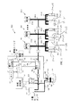
図1を参照すると、潤滑システム100の例示的な実施形態が示されている。図1が示すように、潤滑システム100は、ドライルーブ104を含み、該ドライルーブは本例ではドラム102内に入れられている。主ルーブポンプ110は、ピックアップライン108及びピックアップ部106を介してドラム102内のドライルーブ104に流体連通している。一実施形態において、主ルーブポンプ110が作動しない場合、予備ルーブポンプ111が使用される。予備ルーブポンプ111もまた、ピックアップライン108及びピックアップ部106を介してドライルーブ104に流体連通している。以下、主ルーブポンプ110及び予備ルーブポンプ111を概して、ポンプ110及びポンプ111という。ポンプ110、又は必要に応じてポンプ111は、ピックアップ部106及びピックアップライン108によってルーブ104をドラム102から汲み上げて主ルーブライン115に送り込む。図1の実施形態において、ポンプ110及び111は、空気供給部112により作動される空気ポンプである。主ライン115内の逆止弁124は、ポンプ110及び111がポンプ動作を行っていないとき、ポンプ110及び111に圧力が及ばないように使用される。これにより、背圧によってルーブがポンプ110又は111のダイアフラム(図示せず)まで圧送されるのを防ぐ。更に、逆止弁124は、ポンプ110又は111が作動しているとき、ポンプ110又は111に確実に圧力がかからないようにする。これにより、ポンプ110又は111が異常停止するのを防ぐ。図1にはまた、主ルーブライン115内の圧力を表示する圧力計140が示されている。
With reference to FIG. 1, an exemplary embodiment of a
上述のように、ポンプ110及び111は、空気供給部112によって作動される。空気供給部112は、起動回路を用いて操作され、該起動回路は、電力供給部118と、ポンプエアソレノイド116と、圧力スイッチ120とを含む。図示されるように、ポンプエアソレノイド116は、圧力スイッチ120が閉じているとき、空気供給部112を作動させる。運転中、本実施形態の圧力スイッチ120は、通常閉じており、選択圧力に達すると開くスイッチである。例えば、圧力スイッチ120は、主ルーブライン115内の圧力が40PSIに達すると開き、主ルーブライン115内の圧力が35PSIより低くなるまで開いたままであってもよい。それ故、本実施形態において、ポンプ110又は111は、主ライン115内の圧力が40PSIに達すると停止され、その後主ライン115内の圧力が35PSIまで下がると再び起動される。実施形態において使用され得るスイッチの一例としては、作動範囲が30〜50PSIであるSquare D Manufacture社製のスイッチ型番FSG2121CPがある。
As described above, the
図1の実施形態は更に、警報回路130を含み、該警報回路は、問題がある場合にルーブポンプ110及び111を停止するために使用される。警報回路130は、警報スイッチ132を操作し、警報スイッチを開くことで起動回路がポンプ110及び111を操作するのを防ぐ。本実施形態において、警報回路103は、ルーブレベル低下回路128からのルーブ低下表示信号を受信するように連結される。本実施形態において、レベル低下回路128は、樽102内においてピックアップ部106に取り付けられたフロート126を用いて、ルーブ104のレベルが低下した場合に表示する。この警報は、空気がポンプ110又は111内に送り込まれるのを防ぐ。空気が誤ってピックアップライン108に侵入しポンプ110又は111内に入ってしまった場合、ポンプ110又は111を使用可能とするには、これらに再び呼び水をしなければならない。従って、レベル低下回路128は、ルーブ104の不足によりポンプ110又は111に再び呼び水をしなければならない事態を防ぐ。本実施形態の警報回路130はまた、タイマー回路134に接続され、該タイマー回路は、ルーブポンプ110又は111の作動時間を監視する。ルーブポンプ110又は111が予定時間よりも長い時間作動している場合、警報回路130が警報スイッチ132を開くことによりルーブポンプ110又は111を停止する。ルーブポンプ110又は111が予定よりも長く作動している状態は、潤滑システム100内の漏出を示唆し得る。一実施形態において、警報スイッチ132は、問題が修正されたら警報システムをリセットするために手動で閉じなければならない。
The embodiment of FIG. 1 further includes an
図示されるように、潤滑システム100は、主分配ライン115と、供給ライン150−1〜150−Nとを含む。供給ライン150−1〜150−Nは、ルーブ102を各ゾーン152,154及び156へ送るための通路を提供する。ゾーン152,154及び156は、当該技術において公知の手段により潤滑剤が分配される箇所である。図1の実施形態において、供給ライン150−1はゾーン152−1〜152−Nを含み、供給ライン150−2はゾーン154−1〜154−Nを含み、供給ライン150−Nはゾーン156−1〜156−Nを含む。更に図1に図示されるように、各供給ライン150−1〜150−Nは、独自の蓄圧器151−1〜151−Nを含む。詳細には、供給ライン150−1は蓄圧器151−1を含み、供給ライン150−2は蓄圧器151−2を含み、供給ライン150−Nは蓄圧器151−Nを含む。蓄圧器151−1〜151−N(以下、総称して蓄圧器151という)は、使用箇所において圧力を蓄積するため、中央位置にあるポンプから圧力を受ける必要がない。蓄圧器151は、管路158を介して各マニホールド160に連結される。詳細には、蓄圧器151−1は管路158−1を介してマニホールド160−1に連結され、蓄圧器151−2は管路158−2を介してマニホールド160−2に連結され、蓄圧器151−Nは管路158−Nを介してマニホールド160−Nに連結される。実施形態は、既存の潤滑システムを改良するために使用することができる。例えば、図1に関して、もともと湿性潤滑剤を送出するために設計され、主ライン115と供給管路158−1〜158−Nを含んでいたシステムに対し、蓄圧器151−1〜151−Nを各供給管路158−1〜158−Nに取り付けて使用することにより、上述のドライルーブ送出システムを後付けすることが可能である。従って、実施形態は、新規設置に限定されない。
As shown, the
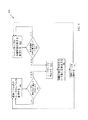
図2を参照すると、実施形態の供給ライン200の一例が詳しく示されている。図示されるように、蓄圧器202は、供給管路204を介してマニホールド206に連結される。供給管路204は、図示されるように主ルーブライン115からルーブを受け取る。マニホールド206は、通路205−1,205−2及び205−3を提供し、該通路は、対応するゾーン207−1,107−2及び207−3へと延びる。三つのゾーン207−1〜207−3が図示されているが、用いられるゾーンの数は、その塗布状況に応じて変わる。従って、本出願は、そのゾーン数や供給ライン数に限定されない。図2に示されるように、電磁弁208−1,208−2及び208−3が、マニホールド206と各ゾーン207−1,207−2及び207−3との間に配置される。詳細には、電磁弁208−1はマニホールド206とゾーン207−1との間に配置され、電磁弁208−2はマニホールド206とゾーン207−2との間に配置され、電磁弁208−3はマニホールド206とゾーン207−3との間に配置される。電磁弁208−1,208−2及び208−3は、ゾーン207−1,207−2及び207−3へと送るルーブ104の流量を調節するために用いられる。電磁弁208−1〜208−3は、コントローラー210によって制御される。コントローラー210は、個々のゾーン207−1,207−2及び207−3のルーブ要求に基づいて各電磁弁208−1,208−2及び208−3を制御する。詳細には、コントローラー210は、所望の抵抗係数を得るために、電磁弁208−1,208−2及び208−3(以下、総称して電磁弁208という)の作動頻度のみならず電磁弁208の開放継続時間を制御する。この作動頻度及び開放継続時間は、個々のゾーン207−1,207−2及び207−3毎のルーブ要求に基づく。各ゾーン207−1〜207−3は、独自の作動頻度及び時間を要求してもよい。一実施形態において、コントローラー210は、Ecolab社のDryExxコントローラーなどのタイマーを組み込んだ機械装置である。別の実施形態においては、コントローラー210は、プログラマブルロジックコントローラーである。更に別の実施形態においては、コントローラー210は、警報回路130への通信接続部212を有する。この実施形態において、コントローラー210は、潤滑システム100に関する問題を知らせる警報回路信号を警報回路130から受け取ると、電磁弁208を閉じる。このようにして問題が生じると潤滑システム100全体を効果的に停止させる。
Referring to FIG. 2, an example of the
一実施形態において、蓄圧器202は、21PSIの圧力を予め封入した2ガロンの圧力溜めタンク(pressure well tank)である。このような圧力溜めタンクの一例は、Water Worker社製の型番HT−2である。この型の蓄圧器は、故障の可能性が低いため望ましい。これは、圧力溜めタンクの用途において対処を強いられていた状況とは異なり、結露が生じない周囲温度において使用されるからである。その上、シリコンベースの潤滑剤は、圧力溜めタンク内のブラダーの寿命を延ばすことが見込まれる。一実施形態において、供給ライン204には、主ルーブライン115の直径よりも大きい直径を有するものが使用される。これにより、遠く離れた各ゾーンに至るまでの圧力損失を最小限にする。一実施形態において、3/4インチの管が供給管路204に使用され、1/2インチの管が主ルーブライン115(又は主分配ライン115)に使用される。更に、一実施形態において、ポリ塩化ビニル管が、供給管路204及び主分配ライン115に使用される。
In one embodiment, the
図3は、実施形態の潤滑システムのフローチャート300を示す。図示されるように、主ルーブライン内の圧力に基づいてルーブポンプを作動させることにより工程を開始する(ステップ302)。次にポンプは、ルーブをルーブ容器から汲み上げ主ルーブラインに送る(ステップ304)。その間、圧力が供給ラインに提供される(ステップ306)。各供給ラインは、本実施形態では、対応する蓄圧器から圧力を受ける。各供給ラインは、主ルーブラインからルーブを提供される(ステップ308)。各供給ライン内のルーブは、選択的に対応ゾーンへと送られて、該対応ゾーンを潤滑する(ステップ310)。
FIG. 3 shows a
図4を参照すると、一実施形態の警報のフローチャートが示されている。本実施形態において、送出容器内のルーブのレベルが監視される(ステップ402)。レベルが選択レベルより低いかどうかが判定される(ステップ404)。レベルが選択レベルより低くない場合(ステップ404)、(ステップ402)においてレベルは引き続き監視される。レベルが選択レベルより低い場合(ステップ404)、ポンプは停止される(ステップ410)。空の容器が新しいルーブ容器と交換されたことを示す信号が受信される(ステップ412)まで、ポンプは停止されたままとなる。該信号が受信されると、潤滑システムは再開され(ステップ414)、(ステップ402)においてルーブのレベルが再び監視される。フローチャートが同様に示すように、ルーブポンプの作動時間の長さも監視される(ステップ406)。作動時間長さが所定の時間長さを越えているかどうかが判定される(ステップ408)。ポンプの作動時間が選択された時間長さを越えない場合(ステップ408)、(ステップ406)においてポンプの作動時間は引き続き監視される。ポンプの作動時間が選択された時間長さよりも長い場合(ステップ408)、ルーブポンプは停止される(ステップ410)。システムにおける問題が修正されたことを示す信号が受信される(ステップ412)まで、ポンプは停止されたままとなる。該信号が受信されると、潤滑システムは再開され(ステップ414)、(ステップ406)においてポンプの作動時間長さが再び監視される。 Referring to FIG. 4, an alarm flowchart of one embodiment is shown. In this embodiment, the level of the lube in the delivery container is monitored (step 402). It is determined whether the level is lower than the selection level (step 404). If the level is not lower than the selected level (step 404), the level is still monitored in (step 402). If the level is lower than the selected level (step 404), the pump is stopped (step 410). The pump remains stopped until a signal is received indicating that the empty container has been replaced with a new lube container (step 412). When the signal is received, the lubrication system is resumed (step 414) and the level of the lube is monitored again (step 402). As the flow chart similarly shows, the length of time the lube pump is operating is also monitored (step 406). It is determined whether the operating time length exceeds a predetermined time length (step 408). If the pump operating time does not exceed the selected length of time (step 408), the pump operating time is continuously monitored in (step 406). If the pump operating time is longer than the selected length of time (step 408), the lube pump is stopped (step 410). The pump remains stopped until a signal is received indicating that the problem in the system has been corrected (step 412). When the signal is received, the lubrication system is restarted (step 414) and the length of pump operation is monitored again at (step 406).
一実施形態によるゾーンでの分配のフローチャート500が、図5に示される。図示されるように、本工程は、各ゾーンにおけるルーブの分配時間の長さを設定すること(ステップ502)、及び各ゾーンにおけるルーブの分配頻度を設定すること(ステップ504)により開始する。上述のように、分配の長さ及び頻度は、ゾーンにおいて要求される個別の塗布状況に左右される。例えば、コンベヤーシステムにおいて、ボトル等の製品が所望通りにコンベヤー上を移動するように、ある一定の抵抗係数を得ることが望ましい。選択すべき抵抗係数の決定、並びに選択された抵抗係数を実現するルーブの分配時間の長さ及び頻度は、実験によって、又は当技術分野で知られている公式によって割り出すことができる。各ゾーン毎の分配時間及び分配頻度が認識されると、それに従ってルーブが分配される(ステップ506)。一実施形態において、ルーブのゾーンへの分配を制御するコントローラーは、潤滑システムに関する問題を知らせる警告信号に備えて警報コントローラーを監視する(ステップ508)。信号が検出されなければ(ステップ510)、システムは監視を継続する(ステップ508)。信号が検出されると(ステップ510)、ルーブのゾーンへの分配は停止される(ステップ512)。問題が修正されたという信号が受信されると(ステップ514)、(ステップ506)においてシステムはルーブの分配を継続する。
A
図1の警報回路103の幾つかの実施形態及び図2のプログラマブルロジックコントローラー210は、処理装置と、図4及び図5のフローチャートで説明されたステップの実行命令を格納する記憶装置とを組み込んでいる。処理装置は、様々な方法、処理作業、計算及び制御機能を実行するためのソフトウェアプログラム、ファームウェア又はコンピューター読取可能な命令を含み、又はこれらと共に機能する。これらの命令は典型的に、コンピューター読取可能な命令又はデータ構造を格納するために使用される任意の適切な記録媒体上で明確に具体化される。このようなコンピューター読取可能な記録媒体は、多目的又は特殊目的のコンピューターや処理装置、又は任意のプログラマブルロジックデバイスによってアクセスが可能である、任意の入手可能な記録媒体でよい。好適なコンピューター読取可能な記録媒体は、ディスクすなわちCD−ROM等の磁気媒体や光学式媒体といった記憶媒体、又はRAM(例えば、SDRAM,DDR SDRAM,RDRAM,SRAM等)、ROM、EEPROM、フラッシュメモリー等といった揮発性媒体若しくは不揮発性媒体を含んでもよい。
Some embodiments of the alarm circuit 103 of FIG. 1 and the
本明細書中で特定の実施形態が図示され説明されたが、同じ目的を達成するように意図される任意の構成を、示された特定の実施形態の代わりに用いてもよいことが当業者によって理解されるであろう。例えば、上記の説明はシステムに潤滑をもたらすためのルーブの送り出しに関する。しかしながら、本発明は、化学薬品や農薬等の他の物質を塗布するための実施形態の使用を考慮している。従って、本出願は、本発明のあらゆる適応例又は変形例を包含することが意図される。その結果、本発明は特許請求の範囲及びその均等物によってのみ制限されることが明白に意図される。 Although specific embodiments have been illustrated and described herein, those skilled in the art will appreciate that any configuration intended to accomplish the same purpose may be used in place of the specific embodiments shown. Will be understood. For example, the above description relates to feeding a lube to provide lubrication to the system. However, the present invention contemplates the use of embodiments for applying other substances such as chemicals and pesticides. Accordingly, this application is intended to cover any adaptations or variations of the present invention. As a result, it is manifestly intended that this invention be limited only by the claims and the equivalents thereof.
Claims (23)
主分配ラインと、
物質を汲み上げて主分配ラインに送る主ポンプと、
主分配ラインに設けられ、主分配ライン内の選択圧力を維持するために主ポンプの運転を制御する圧力スイッチと、
少なくとも一つの供給ラインとを備え、
各供給ラインが、
主分配ラインに連結されて同主分配ライン内の物質を受け取る供給管路と、
供給管路内に選択圧力を提供するために連結される蓄圧器と、
入口及び少なくとも一つの出口を有するマニホールドであって、マニホールドの入口が供給管路に連結され、各出口が物質を分配ゾーンに出力するマニホールドと、を含むことを特徴とする蓄圧タンクシステム。 An accumulator tank system for applying a substance,
A main distribution line;
A main pump that pumps material and sends it to the main distribution line;
A pressure switch provided in the main distribution line for controlling the operation of the main pump to maintain a selected pressure in the main distribution line;
And at least one supply line,
Each supply line
A supply line connected to the main distribution line to receive material in the main distribution line;
An accumulator coupled to provide a selected pressure in the supply line;
A pressure accumulator tank system comprising: a manifold having an inlet and at least one outlet, wherein the manifold inlet is connected to a supply line, each outlet outputting a substance to a distribution zone.
圧力スイッチに連結され、更に空気供給部を制御するように連結されるポンプエアソレノイドと、
圧力スイッチが閉じているとき、ポンプエアソレノイドに電力を供給するように連結される電力供給部とを更に備えることを特徴とする請求項5に記載のシステム。 An air supply connected to output an air flow for operating the main pump;
A pump air solenoid coupled to the pressure switch and further coupled to control the air supply;
6. The system of claim 5, further comprising a power supply coupled to supply power to the pump air solenoid when the pressure switch is closed.
各弁を制御するために連結される少なくとも一つのコントローラーとを更に備えることを特徴とする請求項1に記載のシステム。 A valve provided at each output port of the manifold for adjusting the flow rate of the lube discharged from the manifold to the corresponding zone;
The system of claim 1, further comprising at least one controller coupled to control each valve.
主ラインと、
ドライルーブを汲み上げて主ラインに送るために連結されるポンプと、
主ライン内の所望圧力を維持する目的でポンプの運転を制御するために連結される圧力スイッチと、
複数の供給ラインとを備え、各供給ラインが、ルーブを受け取るために主ラインに連結される供給管路を有し、各供給ラインが更に、対応する供給管路内に選択圧力を提供するために連結される蓄圧器を有し、各供給ラインが更に、供給管路に連結される入力口と、分配ゾーンに向けてルーブを出力する少なくとも一つの出力口とを備えたマニホールドを有することを特徴とする潤滑用蓄圧タンクシステム。 An accumulator tank system for lubrication,
The main line,
A pump connected to pump up the dry lube and send it to the main line;
A pressure switch coupled to control the operation of the pump for the purpose of maintaining the desired pressure in the main line;
A plurality of supply lines, each supply line having a supply line coupled to the main line for receiving a lube, each supply line further providing a selected pressure in the corresponding supply line Each supply line further has a manifold with an input port connected to the supply line and at least one output port for outputting a lube toward the distribution zone. Features a pressure accumulation tank system for lubrication.
各弁を制御するために連結される少なくとも一つのコントローラーと、を更に備えることを特徴とする請求項13に記載のシステム。 A valve provided at each output port of the manifold for adjusting the flow rate of the lube discharged from the manifold to the corresponding zone;
The system of claim 13, further comprising at least one controller coupled to control each valve.
ポンプを作動させるために空気流を出力するように連結される空気供給部と、
圧力スイッチに連結され、更に空気供給部を制御するように連結されるポンプエアソレノイドと、
圧力スイッチが閉じているとき、ポンプエアソレノイドに電力を供給するように連結される電力供給部とを更に備えることを特徴とする請求項13に記載のシステム。 The pump is an air pump,
An air supply coupled to output an air flow to operate the pump;
A pump air solenoid coupled to the pressure switch and further coupled to control the air supply;
14. The system of claim 13, further comprising a power supply coupled to supply power to the pump air solenoid when the pressure switch is closed.
物質を汲み上げて主分配ラインへ送ることと、
主分配ライン内の選択圧力を維持することと、
少なくとも一つの蓄圧器を用いて、主分配ラインに連結された少なくとも一つの供給ライン内に圧力を提供することと、
少なくとも一つの供給ラインに連結されたマニホールドを介して少なくとも一つの選択ゾーンに物質を分配することとを含む方法。 A method of dispensing a substance,
Pumping material to the main distribution line;
Maintaining selected pressure in the main distribution line;
Providing pressure in at least one supply line coupled to the main distribution line using at least one pressure accumulator;
Distributing the material to at least one selected zone via a manifold coupled to the at least one supply line.
供給容器内の物質のレベルが低い場合に主分配ラインへの物質の汲み上げを停止することと、を更に含む請求項19に記載の方法。 Monitoring the level of the substance in the supply container;
20. The method of claim 19, further comprising stopping pumping of material to the main distribution line when the level of material in the supply container is low.
ポンプの汲み上げ時間が選択時間を越えた場合、主分配ラインへの物質の汲み上げを停止することと、を更に含む請求項19に記載の方法。 Monitoring the length of time the pump is pumping material into the main distribution line;
20. The method of claim 19, further comprising: stopping pumping of material to the main distribution line if the pump pumping time exceeds a selected time.
各ゾーンにおける物質の分配頻度を設定することと、を更に含む請求項19に記載の方法。 Setting the length of time for substance distribution in each zone;
20. The method of claim 19, further comprising: setting a substance distribution frequency in each zone.
Applications Claiming Priority (3)
| Application Number | Priority Date | Filing Date | Title |
|---|---|---|---|
| US12/394,640 US20100219020A1 (en) | 2009-02-27 | 2009-02-27 | Pressure accumulator tank system for applying a substance |
| US12/394,640 | 2009-02-27 | ||
| PCT/IB2010/050854 WO2010097780A2 (en) | 2009-02-27 | 2010-02-26 | Pressure accumulator tank system for applying a substance |
Related Child Applications (1)
| Application Number | Title | Priority Date | Filing Date |
|---|---|---|---|
| JP2015000419U Continuation JP3196954U (en) | 2009-02-27 | 2015-01-30 | Accumulation tank system for applying substances |
Publications (2)
| Publication Number | Publication Date |
|---|---|
| JP2012519256A true JP2012519256A (en) | 2012-08-23 |
| JP2012519256A5 JP2012519256A5 (en) | 2013-04-11 |
Family
ID=42666001
Family Applications (2)
| Application Number | Title | Priority Date | Filing Date |
|---|---|---|---|
| JP2011551563A Pending JP2012519256A (en) | 2009-02-27 | 2010-02-26 | Accumulation tank system for applying substances |
| JP2015000419U Expired - Lifetime JP3196954U (en) | 2009-02-27 | 2015-01-30 | Accumulation tank system for applying substances |
Family Applications After (1)
| Application Number | Title | Priority Date | Filing Date |
|---|---|---|---|
| JP2015000419U Expired - Lifetime JP3196954U (en) | 2009-02-27 | 2015-01-30 | Accumulation tank system for applying substances |
Country Status (5)
| Country | Link |
|---|---|
| US (1) | US20100219020A1 (en) |
| JP (2) | JP2012519256A (en) |
| CN (1) | CN102333711A (en) |
| CA (1) | CA2750012A1 (en) |
| WO (1) | WO2010097780A2 (en) |
Cited By (2)
| Publication number | Priority date | Publication date | Assignee | Title |
|---|---|---|---|---|
| CN106949369A (en) * | 2017-03-03 | 2017-07-14 | 杭州江河机电装备工程有限公司 | Concrete batching and mixing tower centralized lubricating system and method |
| KR101778269B1 (en) | 2016-07-12 | 2017-09-13 | 박병권 | High efficiency automatic fluid supply equipment |
Families Citing this family (9)
| Publication number | Priority date | Publication date | Assignee | Title |
|---|---|---|---|---|
| US20110290589A1 (en) * | 2008-11-10 | 2011-12-01 | Kelsan Technologies Corp | Consumable Applicator |
| AU2010286339A1 (en) * | 2009-08-28 | 2012-02-23 | Ifield Engineering Pty Limited | Improved system for automatic lubrication |
| KR101360983B1 (en) * | 2013-05-21 | 2014-02-11 | 주식회사 한일루브텍 | Lubrication pump |
| US10753535B2 (en) * | 2016-03-22 | 2020-08-25 | Gjr Meyer Service, Inc. | Lubrication manifold |
| EP3440396B1 (en) * | 2016-04-08 | 2023-12-27 | Hexagon Technology AS | System with remotely controlled, pressure actuated tank valve |
| IT201600100783A1 (en) * | 2016-10-07 | 2018-04-07 | Dropsa Spa | Semi-solid lubricant distribution system and method for controlling this system |
| US11725778B2 (en) * | 2018-04-03 | 2023-08-15 | DUALCO, Inc. | Automated multi-valve/point lube system |
| CN111268636A (en) * | 2020-03-04 | 2020-06-12 | 中国五冶集团有限公司 | Refueling island system |
| CN113431647A (en) * | 2021-07-13 | 2021-09-24 | 杭州国能汽轮工程有限公司 | Efficient oil station device with online oil purification function |
Family Cites Families (34)
| Publication number | Priority date | Publication date | Assignee | Title |
|---|---|---|---|---|
| US715717A (en) * | 1902-04-18 | 1902-12-09 | George Whitaker | Lubricator. |
| US2164273A (en) * | 1937-01-21 | 1939-06-27 | Hodson Corp | Multiple pressure lubricator |
| US3145803A (en) * | 1962-10-09 | 1964-08-25 | Arthur J Cobert | Centralized lubrication system |
| US3481431A (en) * | 1966-08-18 | 1969-12-02 | Mason H Dorsey | Lubrication system |
| US3995717A (en) * | 1974-09-19 | 1976-12-07 | Houdaille Industries, Inc. | Sequential lubrication distributor and lubricant injector therefor |
| US4007826A (en) * | 1976-04-02 | 1977-02-15 | Stephens-Adamson, Inc. | Dual pressure take-up apparatus and system for dual belt conveyor-elevator |
| US4085821A (en) * | 1976-09-07 | 1978-04-25 | Madison-Kipp Corporation | Lubrication system |
| US4199950A (en) * | 1977-12-01 | 1980-04-29 | Hakason Alton L | Prelubricating and lubricating systems for engines |
| US4196748A (en) * | 1977-12-16 | 1980-04-08 | Stauffer Chemical Company | Multiple strength fluid distribution apparatus |
| US4271930A (en) * | 1978-05-05 | 1981-06-09 | Madison-Kipp Corporation | Enclosed lubricating apparatus |
| JPS58202310A (en) * | 1982-05-19 | 1983-11-25 | Hitachi Ltd | Early starting method and its device of emergency oil pump in oil supply equipment for turbine |
| US4537285A (en) * | 1983-04-11 | 1985-08-27 | Brown Patrick A | Conveyor lubricating apparatus |
| US4520902A (en) * | 1983-04-19 | 1985-06-04 | Lubriquip-Houdaille, Inc. | Lubricant applying system and injector means |
| ZA873002B (en) * | 1986-05-01 | 1987-11-25 | Castrol Ltd | Lubrication devices |
| US4844203A (en) * | 1988-01-29 | 1989-07-04 | Patco Sales & Service, Inc. | Self contained conveyor lubricating apparatus |
| US4977979A (en) * | 1989-03-28 | 1990-12-18 | Sauk Valley Equipment Company | Lubrication system |
| US5247957A (en) * | 1991-10-24 | 1993-09-28 | H. B. Fuller Company | Modular lubrication multiple concentration control apparatus |
| US5129481A (en) * | 1992-01-29 | 1992-07-14 | Pure-Chem Products Company, Inc. | Apparatus and method for lubricating conveyors |
| US5285871A (en) * | 1992-08-17 | 1994-02-15 | Mechanical Tool & Engineering Co. | System for distributing viscous lubricant |
| JPH06169545A (en) * | 1992-12-01 | 1994-06-14 | Fuji Electric Co Ltd | Protective apparatus for lubricating means for bearing of rotating machine |
| US5531085A (en) * | 1994-05-05 | 1996-07-02 | Hayes; John W. | Die lubricant applicator |
| JPH09100838A (en) * | 1995-10-03 | 1997-04-15 | Toshiba Corp | Bearing device |
| DE19756328C2 (en) * | 1997-12-18 | 2001-02-22 | Man Takraf Foerdertechnik Gmbh | Hydraulic tensioning device for belt conveyor |
| US6053285A (en) * | 1998-01-14 | 2000-04-25 | G.P. Reeves, Inc. | Apparatus for dispensing measured quantities of lubricant |
| US6176348B1 (en) * | 1998-07-31 | 2001-01-23 | Perma-Tec Gmbh & Co. Kg | Multiple-pump system for lubricating |
| US6286627B1 (en) * | 1999-08-25 | 2001-09-11 | Lincoln Industrial Corporation | Fluid dispensing apparatus |
| US6540104B1 (en) * | 2000-06-30 | 2003-04-01 | Fanuc Robotics North America, Inc. | Integral pneumatic dispenser and method for controlling same |
| US6576298B2 (en) * | 2000-09-07 | 2003-06-10 | Ecolab Inc. | Lubricant qualified for contact with a composition suitable for human consumption including a food, a conveyor lubrication method and an apparatus using droplets or a spray of liquid lubricant |
| US6688434B2 (en) * | 2002-02-22 | 2004-02-10 | Ecolab Inc. | Conveyor and lubricating apparatus, lubricant dispensing device, and method for applying lubricant to conveyor |
| GB0218849D0 (en) * | 2002-08-14 | 2002-09-25 | Rolls Royce Plc | Lubrication system for gas turbine engine |
| JP2006258263A (en) * | 2005-03-18 | 2006-09-28 | Nsk Ltd | Lubricant feeding device, lubricant feeding method, bearing device and spindle device |
| JP4268631B2 (en) * | 2006-11-21 | 2009-05-27 | 日本精工株式会社 | Bearing device |
| CN200981765Y (en) * | 2006-11-23 | 2007-11-28 | 江阴华峥特种运输机械有限公司 | Centralized lubricating system for belt feeder |
| US20090071754A1 (en) * | 2007-09-17 | 2009-03-19 | Mcarthur Malcolm J | Metering Lubrication oil at low flow rates |
-
2009
- 2009-02-27 US US12/394,640 patent/US20100219020A1/en not_active Abandoned
-
2010
- 2010-02-26 WO PCT/IB2010/050854 patent/WO2010097780A2/en active Application Filing
- 2010-02-26 CA CA 2750012 patent/CA2750012A1/en not_active Abandoned
- 2010-02-26 JP JP2011551563A patent/JP2012519256A/en active Pending
- 2010-02-26 CN CN2010800093612A patent/CN102333711A/en active Pending
-
2015
- 2015-01-30 JP JP2015000419U patent/JP3196954U/en not_active Expired - Lifetime
Cited By (2)
| Publication number | Priority date | Publication date | Assignee | Title |
|---|---|---|---|---|
| KR101778269B1 (en) | 2016-07-12 | 2017-09-13 | 박병권 | High efficiency automatic fluid supply equipment |
| CN106949369A (en) * | 2017-03-03 | 2017-07-14 | 杭州江河机电装备工程有限公司 | Concrete batching and mixing tower centralized lubricating system and method |
Also Published As
| Publication number | Publication date |
|---|---|
| CN102333711A (en) | 2012-01-25 |
| WO2010097780A2 (en) | 2010-09-02 |
| US20100219020A1 (en) | 2010-09-02 |
| JP3196954U (en) | 2015-04-09 |
| WO2010097780A3 (en) | 2011-01-06 |
| CA2750012A1 (en) | 2010-09-02 |
Similar Documents
| Publication | Publication Date | Title |
|---|---|---|
| JP3196954U (en) | Accumulation tank system for applying substances | |
| US7957841B2 (en) | Method of calculating pump flow rates and an automated pump control system | |
| US8783214B2 (en) | Oil make-up and replenishment oil filter and method of use | |
| JP5015655B2 (en) | Liquid material supply apparatus and liquid material supply method using the same | |
| RU2763295C1 (en) | Alarm control module for sewage pumping station | |
| US20100243070A1 (en) | Device and method for controlling supply of lubricant at a work vehicle | |
| JP5340033B2 (en) | Lubricating oil supply device | |
| US20020125074A1 (en) | Lubrication supply system for a machine | |
| KR101992765B1 (en) | Hybrid water supply system of backdraft prevention and control method thereof | |
| JP2012519256A5 (en) | ||
| US11454115B2 (en) | Method and system for ensuring the quality of a multi-component mixture for rock reinforcement | |
| US11255233B2 (en) | Lubrication liquid delivery methods and apparatus | |
| US20110022237A1 (en) | Dispensing dry lubrication system for a conveyer | |
| US10927829B2 (en) | Pump monitoring method | |
| US11606935B2 (en) | Self-balancing poultry water distribution system | |
| WO2017055994A1 (en) | A compensating device for volumetric pumps | |
| JP7182571B2 (en) | Fluid transfer system and method | |
| JP2011052770A (en) | Lubricating oil supply device | |
| JP2011206776A (en) | Mold-releasing agent pressure-feeding apparatus and method for pressure-feeding mold-releasing agent | |
| JP2012149668A (en) | Lubricant supplying/discharging apparatus | |
| US20170037903A1 (en) | Method of purging lubricant within a bearing and system using the method | |
| WO2020033803A1 (en) | Top fill reservoir system for water purification system | |
| CN220366269U (en) | Lubrication system, distributor and vehicle | |
| KR101448886B1 (en) | Pipe system for preventing reverse current of booster pump | |
| CN217875243U (en) | Centralized lubrication system |
Legal Events
| Date | Code | Title | Description |
|---|---|---|---|
| A521 | Request for written amendment filed |
Free format text: JAPANESE INTERMEDIATE CODE: A523 Effective date: 20130225 |
|
| A621 | Written request for application examination |
Free format text: JAPANESE INTERMEDIATE CODE: A621 Effective date: 20130225 |
|
| A977 | Report on retrieval |
Free format text: JAPANESE INTERMEDIATE CODE: A971007 Effective date: 20140117 |
|
| A131 | Notification of reasons for refusal |
Free format text: JAPANESE INTERMEDIATE CODE: A131 Effective date: 20140121 |
|
| A521 | Request for written amendment filed |
Free format text: JAPANESE INTERMEDIATE CODE: A523 Effective date: 20140421 |
|
| A02 | Decision of refusal |
Free format text: JAPANESE INTERMEDIATE CODE: A02 Effective date: 20140930 |