JP2012509721A - Method and apparatus for small dose treatment of spinal column using irradiated implant - Google Patents
Method and apparatus for small dose treatment of spinal column using irradiated implant Download PDFInfo
- Publication number
- JP2012509721A JP2012509721A JP2011537739A JP2011537739A JP2012509721A JP 2012509721 A JP2012509721 A JP 2012509721A JP 2011537739 A JP2011537739 A JP 2011537739A JP 2011537739 A JP2011537739 A JP 2011537739A JP 2012509721 A JP2012509721 A JP 2012509721A
- Authority
- JP
- Japan
- Prior art keywords
- implant
- seed
- brachytherapy
- radiation
- opening
- Prior art date
- Legal status (The legal status is an assumption and is not a legal conclusion. Google has not performed a legal analysis and makes no representation as to the accuracy of the status listed.)
- Abandoned
Links
- 0 CCCC(*)CCC(C(C1)N)[C@@](*)C(CC(*)*C2)C1*C2O Chemical compound CCCC(*)CCC(C(C1)N)[C@@](*)C(CC(*)*C2)C1*C2O 0.000 description 1
Images


Classifications
-
- A—HUMAN NECESSITIES
- A61—MEDICAL OR VETERINARY SCIENCE; HYGIENE
- A61N—ELECTROTHERAPY; MAGNETOTHERAPY; RADIATION THERAPY; ULTRASOUND THERAPY
- A61N5/00—Radiation therapy
- A61N5/10—X-ray therapy; Gamma-ray therapy; Particle-irradiation therapy
- A61N5/1001—X-ray therapy; Gamma-ray therapy; Particle-irradiation therapy using radiation sources introduced into or applied onto the body; brachytherapy
- A61N5/1027—Interstitial radiation therapy
-
- A—HUMAN NECESSITIES
- A61—MEDICAL OR VETERINARY SCIENCE; HYGIENE
- A61F—FILTERS IMPLANTABLE INTO BLOOD VESSELS; PROSTHESES; DEVICES PROVIDING PATENCY TO, OR PREVENTING COLLAPSING OF, TUBULAR STRUCTURES OF THE BODY, e.g. STENTS; ORTHOPAEDIC, NURSING OR CONTRACEPTIVE DEVICES; FOMENTATION; TREATMENT OR PROTECTION OF EYES OR EARS; BANDAGES, DRESSINGS OR ABSORBENT PADS; FIRST-AID KITS
- A61F2/00—Filters implantable into blood vessels; Prostheses, i.e. artificial substitutes or replacements for parts of the body; Appliances for connecting them with the body; Devices providing patency to, or preventing collapsing of, tubular structures of the body, e.g. stents
- A61F2/02—Prostheses implantable into the body
- A61F2/30—Joints
- A61F2/44—Joints for the spine, e.g. vertebrae, spinal discs
-
- A—HUMAN NECESSITIES
- A61—MEDICAL OR VETERINARY SCIENCE; HYGIENE
- A61F—FILTERS IMPLANTABLE INTO BLOOD VESSELS; PROSTHESES; DEVICES PROVIDING PATENCY TO, OR PREVENTING COLLAPSING OF, TUBULAR STRUCTURES OF THE BODY, e.g. STENTS; ORTHOPAEDIC, NURSING OR CONTRACEPTIVE DEVICES; FOMENTATION; TREATMENT OR PROTECTION OF EYES OR EARS; BANDAGES, DRESSINGS OR ABSORBENT PADS; FIRST-AID KITS
- A61F2/00—Filters implantable into blood vessels; Prostheses, i.e. artificial substitutes or replacements for parts of the body; Appliances for connecting them with the body; Devices providing patency to, or preventing collapsing of, tubular structures of the body, e.g. stents
- A61F2/02—Prostheses implantable into the body
- A61F2/30—Joints
- A61F2/30721—Accessories
- A61F2/30744—End caps, e.g. for closing an endoprosthetic cavity
-
- A—HUMAN NECESSITIES
- A61—MEDICAL OR VETERINARY SCIENCE; HYGIENE
- A61F—FILTERS IMPLANTABLE INTO BLOOD VESSELS; PROSTHESES; DEVICES PROVIDING PATENCY TO, OR PREVENTING COLLAPSING OF, TUBULAR STRUCTURES OF THE BODY, e.g. STENTS; ORTHOPAEDIC, NURSING OR CONTRACEPTIVE DEVICES; FOMENTATION; TREATMENT OR PROTECTION OF EYES OR EARS; BANDAGES, DRESSINGS OR ABSORBENT PADS; FIRST-AID KITS
- A61F2/00—Filters implantable into blood vessels; Prostheses, i.e. artificial substitutes or replacements for parts of the body; Appliances for connecting them with the body; Devices providing patency to, or preventing collapsing of, tubular structures of the body, e.g. stents
- A61F2/02—Prostheses implantable into the body
- A61F2/28—Bones
- A61F2002/2821—Bone stimulation by electromagnetic fields or electric current for enhancing ossification
-
- A—HUMAN NECESSITIES
- A61—MEDICAL OR VETERINARY SCIENCE; HYGIENE
- A61F—FILTERS IMPLANTABLE INTO BLOOD VESSELS; PROSTHESES; DEVICES PROVIDING PATENCY TO, OR PREVENTING COLLAPSING OF, TUBULAR STRUCTURES OF THE BODY, e.g. STENTS; ORTHOPAEDIC, NURSING OR CONTRACEPTIVE DEVICES; FOMENTATION; TREATMENT OR PROTECTION OF EYES OR EARS; BANDAGES, DRESSINGS OR ABSORBENT PADS; FIRST-AID KITS
- A61F2/00—Filters implantable into blood vessels; Prostheses, i.e. artificial substitutes or replacements for parts of the body; Appliances for connecting them with the body; Devices providing patency to, or preventing collapsing of, tubular structures of the body, e.g. stents
- A61F2/02—Prostheses implantable into the body
- A61F2/30—Joints
- A61F2002/30001—Additional features of subject-matter classified in A61F2/28, A61F2/30 and subgroups thereof
- A61F2002/30316—The prosthesis having different structural features at different locations within the same prosthesis; Connections between prosthetic parts; Special structural features of bone or joint prostheses not otherwise provided for
- A61F2002/30329—Connections or couplings between prosthetic parts, e.g. between modular parts; Connecting elements
- A61F2002/30405—Connections or couplings between prosthetic parts, e.g. between modular parts; Connecting elements made by screwing complementary threads machined on the parts themselves
-
- A—HUMAN NECESSITIES
- A61—MEDICAL OR VETERINARY SCIENCE; HYGIENE
- A61F—FILTERS IMPLANTABLE INTO BLOOD VESSELS; PROSTHESES; DEVICES PROVIDING PATENCY TO, OR PREVENTING COLLAPSING OF, TUBULAR STRUCTURES OF THE BODY, e.g. STENTS; ORTHOPAEDIC, NURSING OR CONTRACEPTIVE DEVICES; FOMENTATION; TREATMENT OR PROTECTION OF EYES OR EARS; BANDAGES, DRESSINGS OR ABSORBENT PADS; FIRST-AID KITS
- A61F2/00—Filters implantable into blood vessels; Prostheses, i.e. artificial substitutes or replacements for parts of the body; Appliances for connecting them with the body; Devices providing patency to, or preventing collapsing of, tubular structures of the body, e.g. stents
- A61F2/02—Prostheses implantable into the body
- A61F2/30—Joints
- A61F2002/30001—Additional features of subject-matter classified in A61F2/28, A61F2/30 and subgroups thereof
- A61F2002/30316—The prosthesis having different structural features at different locations within the same prosthesis; Connections between prosthetic parts; Special structural features of bone or joint prostheses not otherwise provided for
- A61F2002/30329—Connections or couplings between prosthetic parts, e.g. between modular parts; Connecting elements
- A61F2002/30476—Connections or couplings between prosthetic parts, e.g. between modular parts; Connecting elements locked by an additional locking mechanism
- A61F2002/30495—Connections or couplings between prosthetic parts, e.g. between modular parts; Connecting elements locked by an additional locking mechanism using a locking ring
-
- A—HUMAN NECESSITIES
- A61—MEDICAL OR VETERINARY SCIENCE; HYGIENE
- A61F—FILTERS IMPLANTABLE INTO BLOOD VESSELS; PROSTHESES; DEVICES PROVIDING PATENCY TO, OR PREVENTING COLLAPSING OF, TUBULAR STRUCTURES OF THE BODY, e.g. STENTS; ORTHOPAEDIC, NURSING OR CONTRACEPTIVE DEVICES; FOMENTATION; TREATMENT OR PROTECTION OF EYES OR EARS; BANDAGES, DRESSINGS OR ABSORBENT PADS; FIRST-AID KITS
- A61F2/00—Filters implantable into blood vessels; Prostheses, i.e. artificial substitutes or replacements for parts of the body; Appliances for connecting them with the body; Devices providing patency to, or preventing collapsing of, tubular structures of the body, e.g. stents
- A61F2/02—Prostheses implantable into the body
- A61F2/30—Joints
- A61F2002/30001—Additional features of subject-matter classified in A61F2/28, A61F2/30 and subgroups thereof
- A61F2002/30316—The prosthesis having different structural features at different locations within the same prosthesis; Connections between prosthetic parts; Special structural features of bone or joint prostheses not otherwise provided for
- A61F2002/30329—Connections or couplings between prosthetic parts, e.g. between modular parts; Connecting elements
- A61F2002/30476—Connections or couplings between prosthetic parts, e.g. between modular parts; Connecting elements locked by an additional locking mechanism
- A61F2002/30507—Connections or couplings between prosthetic parts, e.g. between modular parts; Connecting elements locked by an additional locking mechanism using a threaded locking member, e.g. a locking screw or a set screw
-
- A—HUMAN NECESSITIES
- A61—MEDICAL OR VETERINARY SCIENCE; HYGIENE
- A61F—FILTERS IMPLANTABLE INTO BLOOD VESSELS; PROSTHESES; DEVICES PROVIDING PATENCY TO, OR PREVENTING COLLAPSING OF, TUBULAR STRUCTURES OF THE BODY, e.g. STENTS; ORTHOPAEDIC, NURSING OR CONTRACEPTIVE DEVICES; FOMENTATION; TREATMENT OR PROTECTION OF EYES OR EARS; BANDAGES, DRESSINGS OR ABSORBENT PADS; FIRST-AID KITS
- A61F2/00—Filters implantable into blood vessels; Prostheses, i.e. artificial substitutes or replacements for parts of the body; Appliances for connecting them with the body; Devices providing patency to, or preventing collapsing of, tubular structures of the body, e.g. stents
- A61F2/02—Prostheses implantable into the body
- A61F2/30—Joints
- A61F2002/30001—Additional features of subject-matter classified in A61F2/28, A61F2/30 and subgroups thereof
- A61F2002/30316—The prosthesis having different structural features at different locations within the same prosthesis; Connections between prosthetic parts; Special structural features of bone or joint prostheses not otherwise provided for
- A61F2002/30535—Special structural features of bone or joint prostheses not otherwise provided for
- A61F2002/30537—Special structural features of bone or joint prostheses not otherwise provided for adjustable
- A61F2002/3055—Special structural features of bone or joint prostheses not otherwise provided for adjustable for adjusting length
-
- A—HUMAN NECESSITIES
- A61—MEDICAL OR VETERINARY SCIENCE; HYGIENE
- A61F—FILTERS IMPLANTABLE INTO BLOOD VESSELS; PROSTHESES; DEVICES PROVIDING PATENCY TO, OR PREVENTING COLLAPSING OF, TUBULAR STRUCTURES OF THE BODY, e.g. STENTS; ORTHOPAEDIC, NURSING OR CONTRACEPTIVE DEVICES; FOMENTATION; TREATMENT OR PROTECTION OF EYES OR EARS; BANDAGES, DRESSINGS OR ABSORBENT PADS; FIRST-AID KITS
- A61F2/00—Filters implantable into blood vessels; Prostheses, i.e. artificial substitutes or replacements for parts of the body; Appliances for connecting them with the body; Devices providing patency to, or preventing collapsing of, tubular structures of the body, e.g. stents
- A61F2/02—Prostheses implantable into the body
- A61F2/30—Joints
- A61F2002/30001—Additional features of subject-matter classified in A61F2/28, A61F2/30 and subgroups thereof
- A61F2002/30316—The prosthesis having different structural features at different locations within the same prosthesis; Connections between prosthetic parts; Special structural features of bone or joint prostheses not otherwise provided for
- A61F2002/30535—Special structural features of bone or joint prostheses not otherwise provided for
- A61F2002/30593—Special structural features of bone or joint prostheses not otherwise provided for hollow
-
- A—HUMAN NECESSITIES
- A61—MEDICAL OR VETERINARY SCIENCE; HYGIENE
- A61F—FILTERS IMPLANTABLE INTO BLOOD VESSELS; PROSTHESES; DEVICES PROVIDING PATENCY TO, OR PREVENTING COLLAPSING OF, TUBULAR STRUCTURES OF THE BODY, e.g. STENTS; ORTHOPAEDIC, NURSING OR CONTRACEPTIVE DEVICES; FOMENTATION; TREATMENT OR PROTECTION OF EYES OR EARS; BANDAGES, DRESSINGS OR ABSORBENT PADS; FIRST-AID KITS
- A61F2/00—Filters implantable into blood vessels; Prostheses, i.e. artificial substitutes or replacements for parts of the body; Appliances for connecting them with the body; Devices providing patency to, or preventing collapsing of, tubular structures of the body, e.g. stents
- A61F2/02—Prostheses implantable into the body
- A61F2/30—Joints
- A61F2002/30001—Additional features of subject-matter classified in A61F2/28, A61F2/30 and subgroups thereof
- A61F2002/30316—The prosthesis having different structural features at different locations within the same prosthesis; Connections between prosthetic parts; Special structural features of bone or joint prostheses not otherwise provided for
- A61F2002/30535—Special structural features of bone or joint prostheses not otherwise provided for
- A61F2002/30601—Special structural features of bone or joint prostheses not otherwise provided for telescopic
-
- A—HUMAN NECESSITIES
- A61—MEDICAL OR VETERINARY SCIENCE; HYGIENE
- A61F—FILTERS IMPLANTABLE INTO BLOOD VESSELS; PROSTHESES; DEVICES PROVIDING PATENCY TO, OR PREVENTING COLLAPSING OF, TUBULAR STRUCTURES OF THE BODY, e.g. STENTS; ORTHOPAEDIC, NURSING OR CONTRACEPTIVE DEVICES; FOMENTATION; TREATMENT OR PROTECTION OF EYES OR EARS; BANDAGES, DRESSINGS OR ABSORBENT PADS; FIRST-AID KITS
- A61F2/00—Filters implantable into blood vessels; Prostheses, i.e. artificial substitutes or replacements for parts of the body; Appliances for connecting them with the body; Devices providing patency to, or preventing collapsing of, tubular structures of the body, e.g. stents
- A61F2/02—Prostheses implantable into the body
- A61F2/30—Joints
- A61F2002/30001—Additional features of subject-matter classified in A61F2/28, A61F2/30 and subgroups thereof
- A61F2002/30667—Features concerning an interaction with the environment or a particular use of the prosthesis
- A61F2002/30668—Means for transferring electromagnetic energy to implants
-
- A—HUMAN NECESSITIES
- A61—MEDICAL OR VETERINARY SCIENCE; HYGIENE
- A61F—FILTERS IMPLANTABLE INTO BLOOD VESSELS; PROSTHESES; DEVICES PROVIDING PATENCY TO, OR PREVENTING COLLAPSING OF, TUBULAR STRUCTURES OF THE BODY, e.g. STENTS; ORTHOPAEDIC, NURSING OR CONTRACEPTIVE DEVICES; FOMENTATION; TREATMENT OR PROTECTION OF EYES OR EARS; BANDAGES, DRESSINGS OR ABSORBENT PADS; FIRST-AID KITS
- A61F2/00—Filters implantable into blood vessels; Prostheses, i.e. artificial substitutes or replacements for parts of the body; Appliances for connecting them with the body; Devices providing patency to, or preventing collapsing of, tubular structures of the body, e.g. stents
- A61F2/02—Prostheses implantable into the body
- A61F2/30—Joints
- A61F2/30767—Special external or bone-contacting surface, e.g. coating for improving bone ingrowth
- A61F2/30771—Special external or bone-contacting surface, e.g. coating for improving bone ingrowth applied in original prostheses, e.g. holes or grooves
- A61F2002/30772—Apertures or holes, e.g. of circular cross section
- A61F2002/30784—Plurality of holes
- A61F2002/30785—Plurality of holes parallel
-
- A—HUMAN NECESSITIES
- A61—MEDICAL OR VETERINARY SCIENCE; HYGIENE
- A61F—FILTERS IMPLANTABLE INTO BLOOD VESSELS; PROSTHESES; DEVICES PROVIDING PATENCY TO, OR PREVENTING COLLAPSING OF, TUBULAR STRUCTURES OF THE BODY, e.g. STENTS; ORTHOPAEDIC, NURSING OR CONTRACEPTIVE DEVICES; FOMENTATION; TREATMENT OR PROTECTION OF EYES OR EARS; BANDAGES, DRESSINGS OR ABSORBENT PADS; FIRST-AID KITS
- A61F2/00—Filters implantable into blood vessels; Prostheses, i.e. artificial substitutes or replacements for parts of the body; Appliances for connecting them with the body; Devices providing patency to, or preventing collapsing of, tubular structures of the body, e.g. stents
- A61F2/02—Prostheses implantable into the body
- A61F2/30—Joints
- A61F2/30767—Special external or bone-contacting surface, e.g. coating for improving bone ingrowth
- A61F2/30771—Special external or bone-contacting surface, e.g. coating for improving bone ingrowth applied in original prostheses, e.g. holes or grooves
- A61F2002/30841—Sharp anchoring protrusions for impaction into the bone, e.g. sharp pins, spikes
- A61F2002/30843—Pyramidally-shaped
-
- A—HUMAN NECESSITIES
- A61—MEDICAL OR VETERINARY SCIENCE; HYGIENE
- A61F—FILTERS IMPLANTABLE INTO BLOOD VESSELS; PROSTHESES; DEVICES PROVIDING PATENCY TO, OR PREVENTING COLLAPSING OF, TUBULAR STRUCTURES OF THE BODY, e.g. STENTS; ORTHOPAEDIC, NURSING OR CONTRACEPTIVE DEVICES; FOMENTATION; TREATMENT OR PROTECTION OF EYES OR EARS; BANDAGES, DRESSINGS OR ABSORBENT PADS; FIRST-AID KITS
- A61F2220/00—Fixations or connections for prostheses classified in groups A61F2/00 - A61F2/26 or A61F2/82 or A61F9/00 or A61F11/00 or subgroups thereof
- A61F2220/0025—Connections or couplings between prosthetic parts, e.g. between modular parts; Connecting elements
-
- A—HUMAN NECESSITIES
- A61—MEDICAL OR VETERINARY SCIENCE; HYGIENE
- A61F—FILTERS IMPLANTABLE INTO BLOOD VESSELS; PROSTHESES; DEVICES PROVIDING PATENCY TO, OR PREVENTING COLLAPSING OF, TUBULAR STRUCTURES OF THE BODY, e.g. STENTS; ORTHOPAEDIC, NURSING OR CONTRACEPTIVE DEVICES; FOMENTATION; TREATMENT OR PROTECTION OF EYES OR EARS; BANDAGES, DRESSINGS OR ABSORBENT PADS; FIRST-AID KITS
- A61F2250/00—Special features of prostheses classified in groups A61F2/00 - A61F2/26 or A61F2/82 or A61F9/00 or A61F11/00 or subgroups thereof
- A61F2250/0001—Means for transferring electromagnetic energy to implants
-
- A—HUMAN NECESSITIES
- A61—MEDICAL OR VETERINARY SCIENCE; HYGIENE
- A61F—FILTERS IMPLANTABLE INTO BLOOD VESSELS; PROSTHESES; DEVICES PROVIDING PATENCY TO, OR PREVENTING COLLAPSING OF, TUBULAR STRUCTURES OF THE BODY, e.g. STENTS; ORTHOPAEDIC, NURSING OR CONTRACEPTIVE DEVICES; FOMENTATION; TREATMENT OR PROTECTION OF EYES OR EARS; BANDAGES, DRESSINGS OR ABSORBENT PADS; FIRST-AID KITS
- A61F2310/00—Prostheses classified in A61F2/28 or A61F2/30 - A61F2/44 being constructed from or coated with a particular material
- A61F2310/00005—The prosthesis being constructed from a particular material
- A61F2310/00011—Metals or alloys
- A61F2310/00017—Iron- or Fe-based alloys, e.g. stainless steel
-
- A—HUMAN NECESSITIES
- A61—MEDICAL OR VETERINARY SCIENCE; HYGIENE
- A61F—FILTERS IMPLANTABLE INTO BLOOD VESSELS; PROSTHESES; DEVICES PROVIDING PATENCY TO, OR PREVENTING COLLAPSING OF, TUBULAR STRUCTURES OF THE BODY, e.g. STENTS; ORTHOPAEDIC, NURSING OR CONTRACEPTIVE DEVICES; FOMENTATION; TREATMENT OR PROTECTION OF EYES OR EARS; BANDAGES, DRESSINGS OR ABSORBENT PADS; FIRST-AID KITS
- A61F2310/00—Prostheses classified in A61F2/28 or A61F2/30 - A61F2/44 being constructed from or coated with a particular material
- A61F2310/00005—The prosthesis being constructed from a particular material
- A61F2310/00011—Metals or alloys
- A61F2310/00023—Titanium or titanium-based alloys, e.g. Ti-Ni alloys
-
- A—HUMAN NECESSITIES
- A61—MEDICAL OR VETERINARY SCIENCE; HYGIENE
- A61F—FILTERS IMPLANTABLE INTO BLOOD VESSELS; PROSTHESES; DEVICES PROVIDING PATENCY TO, OR PREVENTING COLLAPSING OF, TUBULAR STRUCTURES OF THE BODY, e.g. STENTS; ORTHOPAEDIC, NURSING OR CONTRACEPTIVE DEVICES; FOMENTATION; TREATMENT OR PROTECTION OF EYES OR EARS; BANDAGES, DRESSINGS OR ABSORBENT PADS; FIRST-AID KITS
- A61F2310/00—Prostheses classified in A61F2/28 or A61F2/30 - A61F2/44 being constructed from or coated with a particular material
- A61F2310/00005—The prosthesis being constructed from a particular material
- A61F2310/00179—Ceramics or ceramic-like structures
-
- A—HUMAN NECESSITIES
- A61—MEDICAL OR VETERINARY SCIENCE; HYGIENE
- A61N—ELECTROTHERAPY; MAGNETOTHERAPY; RADIATION THERAPY; ULTRASOUND THERAPY
- A61N5/00—Radiation therapy
- A61N5/10—X-ray therapy; Gamma-ray therapy; Particle-irradiation therapy
- A61N5/1001—X-ray therapy; Gamma-ray therapy; Particle-irradiation therapy using radiation sources introduced into or applied onto the body; brachytherapy
- A61N2005/1019—Sources therefor
- A61N2005/1024—Seeds
Landscapes
- Health & Medical Sciences (AREA)
- Engineering & Computer Science (AREA)
- Biomedical Technology (AREA)
- Public Health (AREA)
- Orthopedic Medicine & Surgery (AREA)
- Veterinary Medicine (AREA)
- Life Sciences & Earth Sciences (AREA)
- Animal Behavior & Ethology (AREA)
- General Health & Medical Sciences (AREA)
- Radiology & Medical Imaging (AREA)
- Nuclear Medicine, Radiotherapy & Molecular Imaging (AREA)
- Neurology (AREA)
- Pathology (AREA)
- Cardiology (AREA)
- Oral & Maxillofacial Surgery (AREA)
- Transplantation (AREA)
- Heart & Thoracic Surgery (AREA)
- Vascular Medicine (AREA)
- Prostheses (AREA)
- Surgical Instruments (AREA)
- Radiation-Therapy Devices (AREA)
Abstract
【解決手段】 脊柱の腫瘍を容易に集中治療すべく構成された脊柱インプラントであって、腫瘍の放射線治療の線量及び持続期間になるように構成された、複数の照射された移植シードを具備している。
【選択図】 図1A spinal implant configured to facilitate intensive treatment of a spinal tumor, comprising a plurality of irradiated transplant seeds configured to be a dose and duration of tumor radiotherapy. ing.
[Selection] Figure 1
Description
本願は、2008年11月26日に出願された、米国仮特許出願第61/118,235号を基礎とする優先権を主張し、同出願の開示は、その全体がここに明らかにされるが如く、ここに参照によって引用される。
本発明は、照射されたインプラントを用いる脊柱の小線量治療方法及び装置に関する。
This application claims priority based on US Provisional Patent Application No. 61 / 118,235, filed Nov. 26, 2008, the disclosure of which is hereby fully disclosed. Is hereby incorporated by reference.
The present invention relates to a method and apparatus for small dose treatment of the spinal column using irradiated implants.
脊柱腫瘍の治療は、代表的に、腫瘍を取り囲む健康な組織の除去を伴い、悪性細胞が逃げ出して転移するのを防ぐために、腫瘍の外殻を傷つけないようにしている。いくつかの例においては、腫瘍の除去が、腫瘍の外殻を傷つけることを伴う。例えば、腫瘍が脊髄を取り囲んでいる場合には、腫瘍組織を切断して、除去中に腫瘍が脊髄を滑り越えられるようにしている。腫瘍の除去中に腫瘍の外殻が傷つけられるか否かにかかわらず、通常は、転移のリスクを減少させるために、腫瘍の位置に放射線治療を適用することが望ましい。また、放射線治療は、腫瘍を手術できないか、又は外科手術が実際的でないかのいずれかの理由のために、腫瘍が除去されない例においても適用される。 Treatment of spinal tumors typically involves removal of the healthy tissue surrounding the tumor, preventing the malignant cells from escaping and metastasizing so as not to damage the outer shell of the tumor. In some instances, removal of the tumor involves damaging the outer shell of the tumor. For example, if the tumor surrounds the spinal cord, the tumor tissue is cut to allow the tumor to slide over the spinal cord during removal. Regardless of whether the outer shell of the tumor is damaged during tumor removal, it is usually desirable to apply radiation therapy to the location of the tumor to reduce the risk of metastases. Radiation therapy is also applied in instances where the tumor is not removed because either the tumor cannot be operated on or the surgery is not practical.
放射線療法は、従来、一般的に、腫瘍又は切開部位に向けられる、陽子線などの体外の放射源を使用して、脊柱領域に届けられるか、又は代わりに、静脈内への送出を使用して、より体系的に届けられる。残念なことに、従来の放射線療法は、大量の健康な組織を放射に暴露する。 Radiotherapy has traditionally been delivered to the spinal region using an extracorporeal radiation source, such as a proton beam, typically directed to the tumor or incision site, or alternatively using intravenous delivery. And delivered more systematically. Unfortunately, conventional radiation therapy exposes large amounts of healthy tissue to radiation.
小線量治療は、放射線量密度を有するシードを前立腺組織の内部に移植することによって、前立腺癌を隙間から治療するために使用されてきた。低線量放射(LDR)のシードは、前立腺の中に外科的に移植され、永久的に前立腺の中に取り残される。高線量放射(HRD)のシードは、より一時的なベースにおいて、前立腺の中に移植される。 Small dose therapy has been used to treat prostate cancer from the interstices by implanting a seed with radiation dose density inside the prostate tissue. Low dose radiation (LDR) seeds are surgically implanted into the prostate and permanently left in the prostate. High dose radiation (HRD) seeds are implanted into the prostate on a more temporary basis.
従来のLDRシードは、チタンなどのインプラント等級の材料から、所望のサイズに形成されてなる、ケーシングを具備し、放射線材料にて充填される。シードは、ケーシングが1又は複数のペレットに取り付けられてなる行き詰まったシード、又はペレットがなんら他のケーシングに取り付けられていない自由シードとして提供される。ケーシングには、任意の適当なアイソトープを充填でき、これは、求められる放射線照射のレベル及び半減期に依存する。代表的なアイソトープには、ヨー素125及びパラジウム103が含まれる。これら両方の材料は、低エネルギーのX線を継続的に照射し、このX線は短距離だけにしか届かず、放射を周囲の器官に近づけない。 A conventional LDR seed comprises a casing formed from an implant grade material, such as titanium, to a desired size and is filled with a radiation material. Seeds are provided as dead seeds where the casing is attached to one or more pellets, or as free seeds where no pellets are attached to other casings. The casing can be filled with any suitable isotope, depending on the level of radiation required and the half-life. Typical isotopes include iodine 125 and palladium 103. Both these materials continuously emit low energy X-rays that only reach a short distance and do not allow the radiation to approach the surrounding organs.
HDRの小線量治療のシードは、イリジウム195から作られたワイヤを一時的に挿入することを伴い、ワイヤは、パラジウムやヨー素に比べて高いエネルギーのX線を照射する。代表的には、薄いプラスチック製のカテーテルが、テンプレートを通して、前立腺の中に挿入される。イリジウムのワイヤは、一度に1本ずつ、これらのカテーテルに挿入され、例えば2〜3秒間といった短時間だけ、所定位置に維持される。 The seed for HDR small dose treatment involves the temporary insertion of a wire made from iridium 195, which irradiates X-rays of higher energy than palladium or iodine. Typically, a thin plastic catheter is inserted through the template and into the prostate. Iridium wires are inserted into these catheters, one at a time, and held in place for a short period of time, for example 2-3 seconds.
従って、脊柱の腫瘍を治療するために、集中した放射を行うインプラントを提供することが望ましい。 Accordingly, it is desirable to provide an implant that provides focused radiation to treat spinal tumors.
1つの観点によれば、小線源治療用脊柱インプラントが提供され、脊柱インプラントと、複数の放射されたシードとを具備している。脊柱インプラントは、長手軸線に沿って延在する本体と、本体の片側の長手端部に配置された上位終板と、本体の反対側の長手端部に配置された下位終板とを具備し、それぞれの終板が、相補的な椎骨終板に係合すべく構成された椎骨係合面を形成している。インプラント本体に取り付けられた複数の放射線シードは、小線源治療用インプラントが椎骨間空間に配置されたとき、所望の方向において、放射線を脊柱に向けて導くようになっている。 According to one aspect, a brachytherapy spinal implant is provided that includes a spinal implant and a plurality of emitted seeds. The spinal column implant includes a body extending along a longitudinal axis, an upper endplate disposed at one longitudinal end of the body, and a lower endplate disposed at the opposite longitudinal end of the body. Each endplate forms a vertebral engagement surface configured to engage a complementary vertebral endplate. A plurality of radiation seeds attached to the implant body are adapted to direct radiation toward the spinal column in a desired direction when the brachytherapy implant is placed in the intervertebral space.
上述した要旨並びに本願の好ましい実施形態についての以下の詳細な説明は、添付図面に関連させて読むことでより良く理解されるだろう。本願の小線量治療用の放射された脊柱インプラントを例示する目的のために、図面には好ましい実施形態を示している。しかしながら、出願は、図示された正確な構成及び手段に限定されないことを理解されたい。 The foregoing summary, as well as the following detailed description of the preferred embodiments of the present application, will be better understood when read in conjunction with the appended drawings. For the purpose of illustrating the radiated spinal implant for small dose therapy of the present application, the preferred embodiments are shown in the drawings. It should be understood, however, that the application is not limited to the precise arrangements and instrumentalities shown.
ある種の用語は、以下の説明において、便利さのためだけに使用されて、制限的ではない。用語“右側”、“左側”、“下側”、及び“上側”は、図面において参照がされている方向を指示するが、実際の向きは使用中に異なることが認識される。方向を示す用語“内方”及び“外方”は、特に別言しない限り、小線源治療用インプラント20及びそれに関連する部品の幾何学的中心にそれぞれ向かう及び遠のく方向を参照している。用語“遠位側”、“近位側”、“前方”、“後方”、“上位”、“下位”、“内側”、及び“外側”及びこれらの関連語及び/又はフレーズは、限定を意味せず、参照がなされている人体に対して好ましい配置又は向きを指示する。用語には、上に列挙した単語、その派生語、及び類義語が含まれる。
Certain terminology is used in the following description for convenience only and is not limiting. The terms “right side”, “left side”, “lower side”, and “upper side” indicate the direction referenced in the drawings, but it will be appreciated that the actual orientation will be different during use. The directional terms “inward” and “outward” refer to directions toward and away from the geometric center of the
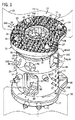
図1を参照すると、小線源治療(近接照射療法)用脊柱インプラント20は、脊柱インプラント21として構成され、これは、1つの実施形態に従って、拡張可能な椎骨間インプラント22として例示され、インプラント22における1又は複数のシード取付位置77に、図示の照射を受けたシード24である、1又は複数の放射線源を保持し又は他の方法にて支持している。照射を受けたシード24は、所定の線量の放射線を照射するように構成されている。インプラント22は、椎体切除術(corpectomy)の拡張可能なスペーサとして図示され、病んだ又は損傷した椎体の少なくとも一部分と置換されるように構成されている。インプラント22は、上位及び下位の終板28及び30をそれぞれ具備し、そのサイズ及び構造は、隣接する椎骨50における対応する隣接係合面と接触するようになっており、隣接する椎骨50によって定められる前彎角度又は後彎角度の範囲に適合するような表面幾何学形状の範囲に提供できる。1つの実施形態においては、隣接する椎骨50の係合面は、椎骨終板を形成する。変形例としては、例えば、半椎体切除術が実行されるときには、一方又は両方の隣接する椎骨50の係合面は、切除された椎骨によって形成される。従って、上位及び下位の終板28及び30は、それぞれ椎骨係合面35及び37を呈し、これは、歯、スパイク、隆起、又はその他のテクスチャ27など、外方へ突出した抗圧出特徴を支持している。終板28及び30は、中心の長手軸線23に沿って延在するインプラント本体26の反対側端部に配置される。
With reference to FIG. 1, a brachytherapy (brachial radiation)
インプラント本体26は、第1のないしは内側の本体部材32であって略管状の形態を有するものと、第2のないしは外側の本体部材34であって略管状の形態を有するものと、拡張リング36とを具備し、これらのすべては中空であり、調整式の椎骨間インプラント22における長手軸線23に沿って、内部に軸線ボアを提供する。本体部材32及び34と、拡張リング36とは、それぞれ、放射状に外面54,56,58を呈している。使用に際しては、第1のないしは内側の部材32は、好ましくは、そのサイズ及び構造が、第2のないしは外側の部材34に比べて若干小さく定められ、第1の部材32が第2の部材34の内部に配置されて可動になっている。しかしながら、他の構成によって可動に関連する、第1の部材32と第2の部材34も想定できることに留意されたい。
The
終板28及び30は、内側及び外側の部材32及び34にそれぞれ結合され、そのためには、当業者に知られた任意の結合機構が用いられ、限定はしないが、締り嵌め、螺合、ねじ止め、接着などが含まれる。図示の通り、インプラント22は、終板キャップ42を具備し、これは、それぞれの上位終板28を通って長手方向に延在してなる中央開口部46の中に挿入され、内側部材32に螺着される。変形例としては、終板キャップ42は、内側部材32と一体的であっても良い。終板キャップ42は、その下端にてベース45に結合された側壁44を形成し、協働して内部空洞48を形成する。従って、外科医は、オステオバイオロジカル(osteobiological)であるか、又はその他の生物学的適合性である材料、例えば、PMMAや骨セメントを空洞48の中に挿入でき、上位椎体50の相補的な終板において、椎骨の融合を促進する。
このように、椎骨間インプラント22は、複数の異なる終板28及び30を備えたキットとして提供でき、従って、ユーザは、患者の椎骨の終板の輪郭に最も良く一致する所望の終板を選択することができる。例えば、様々な終板28及び30が提供され、それらには、限定はしないが、様々な形状、すなわち、円形、正方形、矩形、楕円、腎臓形などが含まれ、及び/又は、1又は複数の以下の特性、すなわち、略楔形状の面、曲面、平坦面などが含まれる。変形例としては、上側及び下側の終板28及び30は、内側及び外側の部材32及び34と共に、一体的に形成しても良い。
Thus, the
拡張リング36の放射状の内面は、ねじを具備し、内側部材32の外側放射状表面に形成されたねじ39と合致するように構成されており、拡張リング36を回転させると、内側部材32が、調整可能な椎骨間インプラント22の長手軸線23に沿って、外側部材34に対して並進し、又は略直線状に移動する。すなわち、使用に際しては、内側及び外側の部材32及び34は、好ましくは、共通の長手軸線23に沿って同軸的に配置され、好ましくは、(例えば、入子式に)互いに対して摺動式に配置されて、内側部材32の軸線位置は外側部材34に対して調整可能になっている。それにより、拡張リング36の回転は、回転の相対的方向に応じて、内側及び外側部材32及び34を拡張又は収縮させることになる。
The radial inner surface of the
1又は複数の止めねじ40は、拡張リング36のねじ開口部41に挿入され、調整可能な椎骨間インプラント22の高さを選択的に係止する。変形例としては、拡張リング36は、自己ロック式でも良い。1つの実施形態においては、止めねじ40は、拡張リング36を自由に回転させて所望の高さを提供するのに充分な深さに位置決めされ、一方、依然として、止めねじ40とこれに対応する開口部41との結合固定を両者間の締り嵌めによって確実にする。適切な器具によって止めねじ40を前進させると、前進した止めねじ40の遠位端が、内側部材32の外面に対して当接し、拡張リング36がさらに回転することを防ぎ、それにより、調整可能な椎骨間インプラント22の高さをロックする。
One or
椎骨間インプラント22は、あらゆる生物学的適合性の材料や、当業者に知られているあらゆる生物学的適合性の材料の組合せから構築することができ、限定はしないが、それらには、ステンレス鋼、チタン、チタン合金、セラミック、及びポリマー、すなわち、限定はしないが、例えば、ポリテトラフルオロエチレン(PTFE)などが含まれる。1つの実施形態においては、内側及び外側の管状部材32及び34は、X線透過性の材料、例えば、ポリマーやポリエーテルエーテルケトン(PEEK)から形成され、一方、拡張リング36は、好ましくは、金属、例えば、チタンやステンレス鋼から形成される。
The
インプラント22は、1又は複数の比較的大きい骨パッキング開口部52を、外側部材34の外面58に形成されて備えている。開口部52は、外側部材34を放射状に又は水平に通って延びる棚部60を形成している。また、インプラント22は、小さい開口部64の配列を具備し、開口部64は図1に示すように内側部材32又はリング部材36に延入しても良いことが認識されるけれども、開口部は、外側部材34の外面58の中に又は通して放射状に延びるように図示されている。1又は複数の骨パッキング開口部52と小さい開口部64とは、インプラント本体26の内側に長手方向に延びてなる内側ボア62へのアクセスを提供する。インプラント22は、開口部52及び64を備えて製造され、又は1又は複数の開口部52及び64は、例えば、外科手順の前に又は最中などに、(例えば、ドリルを用いて)インシトゥーにてインプラントに形成されても良いことを認識されたい。ボア62は、一方又は両方の終板28及び30を延通しても良い。
The
外科医は、オステオバイオロジカル(osteobiological)であるか、又はその他の生物学的適合性である材料、例えば、PMMAや骨セメントを一方又は両方の開口部52及び64を通して骨62の中へ入れて、下位椎体50の終板において、椎骨の融合を促進する。重力は、椎体50の終板に、移植材料の方向を適用するのを補助する。椎骨間インプラント22は、骨パッキング開口部52や小さい開口部64を含むものには限られず、開口部を具備せずとも良く、又はインプラント22の特定の用途又は構造に依存して、追加的な形状又は位置が可変である開口部を具備しても良い。開口部52及び64はさらに、詳しくは後述するように、シード取付位置77を備えても良い。
The surgeon places an osteobiological or other biocompatible material, such as PMMA or bone cement, into
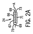
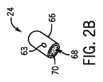
次に図1及び図2を参照すると、小線源治療用インプラント20は、1又は複数の小線源治療用シード24を具備し、これらは、椎骨間インプラント22に嵌められ又は別な方法で取り付けられる。それぞれの小線源治療用シード24は、放射性核種70を収容した内部コア68を形成している、生物学的適合性の保護外殻66を具備している。放射性核種は、任意の適当なアイソトープから選択され、例えば、ヨー素、パラジウム、イリジウムのアイソトープ、又は任意のアイソトープであって所望の線量の放射線を照射するものが含まれる。特定の例によるアイソトープには、ヨー素125及びパラジウム103が含まれ、ヨー素125は低線量の放射線を照射し、また、パラジウム103は高線量の放射線を照射する。従って、放射線シード24は、限られた時間、例えば、2〜3ヶ月にわたって放射線を照射すると良いけれども、治療の好みに応じて、放射線を無期限に又は比較的短時間だけ照射するように構成しても良い。
Referring now to FIGS. 1 and 2, the
外殻66は、あらゆる適当なインプラント等級の材料から構築でき、それらには、例えば、ポリエーテルエーテルケトン(PEEK)、チタン、及びその他のものが含まれる。外殻66は、細長い卵形又は管状の構造物として例示されているけれども、これは、変形例においては、望まれる任意の適当な形状として形成しても良く、例えば、球体、曲線構造、又は任意の所望の多角形構造にすることができる。図示の通り、外殻66は、中心軸線Aに沿って延びてなる、細長い円筒形本体67を形成している。円筒形本体67は、一対の対向する丸められた端部69を形成し、反対側の外側端面73を形成している。円筒形本体67は、反対側の端部69の間に延在してなる外側側面71を形成している。
The
ある種の実施形態においては、放射線を腫瘍に向けて導きつつ、放射線を脊髄から遠ざけるように導くことが望ましい。故に、シード24は、インプラント22において可変に位置決め及び配向させることができ、身体のその他の部分に悪影響を与えない狭い範囲にて治療部位を照射し、一般的に、移植位置とその周囲において、悪性の脊柱腫瘍が成長ないし再成長するのを防ぐように作用する。シード24は、それぞれX線不透過のマーカー63を、外殻66上に又は外殻66の中に配置されて具備し、X線透視術の助けによって治療部位の内部を視認できる。
In certain embodiments, it may be desirable to direct radiation away from the spinal cord while directing radiation toward the tumor. Thus, the
小線源治療用シード24は、1つの実施形態に従って図示して説明されたけれども、シード24は、任意の適当な変形例による実施形態に従って構成しても良いことを認識されたい。例えば、小線源治療用シード24は、放射性核種から構成された、一元的な固体の部材を形成できる。さらに、シード24は、インプラント22の1又は複数の構成要素を提供できることを認識されたい。例えば、抗圧出特徴27は、小線源治療用シード24から形成され、図1に示すように、終板28及び30から長手方向に突出した、スパイク、隆起、テクスチャ、その他を提供するように幾何学的に構成される。
Although the
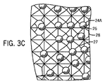
シード24は、望むように、構築され及び/又は配置される。インプラント22は、様々な実施形態によるシード24を具備するものとして示され、1又は複数の第1のシード24A、1又は複数の第2のシード24B、1又は複数の第3のシード24C、1又は複数の第4のシード24D、1又は複数の第5のシード24E、及び1又は複数の第6のシード24Fによって指示されるように構築及び/又は配置されるけれども、インプラント22は、任意の変形例によるタイプのシードを望むようにインプラント22に結合及び配置して具備できることを認識されたい。
The
また図3A乃至図3Eを参照すると、第1のシード24Aは、片方又は両方の終板28及び30に配置され、終板から隣接する椎骨50へ向けて長手方向に延出している。特に、インプラント22は、片方又は両方の終板28及び30の中へ長手方向に延入してなるシード受入れ開口部72として示される、1又は複数のシード取付位置77を具備している。インプラント22は、開口部72を備えて製造され、又は1又は複数の開口部は、例えば、外科手順の前に又は最中などに、(例えば、ドリルを用いて)インシトゥーにてインプラント22に形成されても良いことを認識されたい。
Referring also to FIGS. 3A-3E, the
開口部72は、図示の通り、歯27と組み合わせられて提供されるか、又は歯27の代わりに提供される。第1のシード24Aの外側端部69の片方は、矢印Aの方向に沿った任意の所望の方法にて、開口部72の中へ挿入できる。例えば、開口部72は、第1のシード24A(例えば、外殻66)の外側直径又は代わりに横断面寸法と実質的に等しいような直径又は横断面寸法を形成し、第1のシード24Aは、開口部72の中へ圧入されることができる。代わりに又は加えて、1又は複数の開口部72は、第1のシード24Aに比べて大きい、横断面寸法を形成しても良い。オステオバイオロジカル又はその他の生物学的適合性の材料、例えばPMMAや骨セメントは、開口部72の中へ挿入して、外殻66を片方又は両方の終板28及び30に接着できる。変形例としては、外殻66は、インプラント22に超音波溶接しても良い。
The
開口部72は、片方又は両方の終板28及び30の中へ深さDだけ延入し、この深さは、シード24Aの長手方向長さに比べて短くなっており、シード24Aは、当業者には共通の抗反発歯又はスパイク27と類似して構成及び配置され、小線源治療用脊柱インプラント20の位置ズレを防止する。従って、第1のシード24Aは、椎骨係合面25を呈し、終板28及び30の歯27を補助して、インプラント20を椎骨50に固定するか、又は歯27と置換されて、インプラント20の椎骨50への固定を提供する。椎骨係合面25は、図示のように丸められているか、又は望むならば、スパイク状で、ピラミッド又は円錐の形状であっても良い。インプラント20の拡張、又は代わりに、拡張可能に構築された本体間スペーサは、さらに、第1のシード24Aの表面25を隣接する椎骨終板に貫通させるように促す助けとなる。第1のシード24Aは、外殻66に結合され得る、追加的なクラッディングを具備し、椎骨係合面25にて、隣接する椎骨終板を貫通するような所望の幾何学形状に構成される。所定の1つの開口部72の深さDは、所定のその他の開口部72とは相違しており、シード24Aが、必要に応じて、一方又は両方の終板28及び30から可変長だけ突出するようにさせる。変形例としては、深さDは一定値でも良く、突出の長さLは一定値でも良い。
The
第1のシード24Aは、開口部72が長手軸線Lに対して平行に延びるとき、上位終板28から上方へ突出し、下位終板30から下方へ突出する。変形例としては、開口部72は、長手軸線Lと交差する方向に沿って延び、挿入されたシード24Aの軸線Aは、上位又は下位の方向成分を有する方向へ延び、長手軸線Lに対して斜めに延びても良い。
The
代わりに又は加えて、1又は複数の、又はすべての、開口部72は、シード24Aの長手長さ以上の深さだけ、一方又は両方の終板28及び30の中に延入し、シード24Aは、対応する終板から長手方向に突出することがなく、終板の中に押し込まれる。従って、いくつかのシード24Aは、終板28内に窪み、一方又は両方の終板28及び30から突出しないようにされ、一方、その他のシード24Aは、一方又は両方の終板28及び30から突出して、図3Dのようになる。さらに変形例としては、一方又は両方の終板28及び30の全体は、その外殻が終板28及び30の椎骨係合面の外側を形成するシードとして提供でき、その放射性核種は、上述した方法にて、外殻の内側に配置されることができる。本願に開示されるそれぞれの実施形態においては、放射線は、一方又は両方の終板28及び30からそれぞれ上位及び下位の方向へ外側へ導かれ、腫瘍再発の一般的部位である、隣接する椎体50の中へ入る。
Alternatively or additionally, one or more or all of the
更なる変形例としては、シード24Aは、第2の本体部材34から放射状外方へ延びて、図1に示すように、第2のシード24Bを提供することもできる。特に、シード24Bの片方の外側端部69は、相補的な開口部64の中へ挿入され、開口部は、シード24Bに比べてわずかに大きいか、又は実質的に等しいような直径又は横断面寸法を形成して、シード24Bは、開口部64の中に圧入される。変形例としては、開口部64は、シード24Cに比べて大きいサイズにされ、オステオバイオロジカルであるか、又はその他の生物学的適合性である材料65、例えば、PMMAや骨セメントを開口部64の中に挿入し、外殻66を開口部64の内側にてインプラント22に接着すると良い。変形例としては、外殻66は、インプラント22に超音波溶接しても良い。
As a further variation, the
開口部64は、シード24Bをインプラント22から突出させる深さを有するか、又はシード24Bを窪ませることを許容するか、又はインプラント22の外壁に対して、内方へ変位させることができる。インプラント22が、隣接する椎骨50の間に配置されたとき、開口部64は、前方に、後方に、内側に、外側に、又は両者の間のどこかに対面する。さらに、開口部64は、上位方向において上向きに、又は下位方向において下向きに、角度を付けられる。従って、シード24Bは、開口部64に据え付けられ、放射線を、前方に、後方に、内側に、外側に、又は両者の間のどこかに導く。従って、放射線は、腫瘍の部位へ向けて、かつ、健康な組織から遠ざけて、導かれる。1つの実施形態においては、放射線シード24を、それらが脊髄に向けた方向に延びないように、取り付けることが望ましい。
The
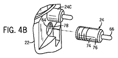
次に図1及び図4A及び図4Bを参照すると、1又は複数の第3のシード24Cは、外殻66から延出してなる結合要素74を具備している。1つの実施形態においては、結合要素74は、インプラント22へシード24Cを取り付けけるのを容易にするため、クラッディング76を具備している。クラッディングは、ポリマー、例えば、ポリエーテルエーテルケトン(PEEK)又はチタン又は任意の代替的なインプラント等級の材料として提供され、インプラント22の一部又は全部と同一の材料から作られる。シード24Cは、外殻66に取り付けられた結合要素74と共に提供され、又は結合要素は、別個に提供され、インシトゥーにて外殻に取り付けられる。1つの実施形態においては、結合要素74は、外殻66に超音波溶接されている。
Referring now to FIGS. 1 and 4A and 4B, the one or more
結合要素74は、開口部64に比べて実質的に等しいか、又はわずかに小さいような直径又は横断面寸法を有し、結合要素は、図4Aに示すように、開口部64の中に圧入される。変形例としては、結合要素74は、開口部64に比べて実質的に小さい直径又は横断面寸法を形成し、外殻66は、開口部64の中に緩く受け入れられて、その中に接着して取り付けられる。結合要素74は、骨セメントを使用してインプラント22に取り付けられるか、又は代替的な接着剤が使用されて、結合要素74をインプラント22の対応する開口部64の中に結合させる。変形例としては、結合要素は、インプラント22に超音波溶接しても良い。更なる変形例としては、結合要素74は、図4Bに示すように、開口部64の対応するねじ付き内面78と螺合するように構成された、ねじ付き外面75を有している。結合要素74は、外殻66の外側端部69の片方に結合され、外殻66の全長に比べて短い、外殻66の長さの一部分に沿って延在し、外殻66の本体部分67を結合要素74から突出させている。
The
図示の通り、外殻66は、結合要素74の中に配置され、結合要素が開口部64の中に挿入されたとき、開口部64に整列され、外殻66はインプラント22から放射状に突出する。変形例としては、外殻66は、結合要素74内に配置され、外殻66は、結合要素74が開口部64の中に据え付けられたとき、開口部64に対して斜めにオフセットした方向に延びている。
As shown, the
結合要素74は、チタン、金、又は任意の所望の材料から作られて、放射線が通り抜けるのを防止し又は著しく制限するような、放射線シールドを提供する。従って、シード24Cは、結合要素74によって被覆されていない箇所から、放射線を照射する。従って、結合要素74を使用して、第2のシード24Cをインプラント22へ結合し又は結合を補助することで、外科医は、第2のシード24Cの位置とインプラント100に結合される第2のシード140bの数とをを選択することによって、小線源治療用脊柱インプラント20からの放射線の照射を仕立てることができる。変形例としては、第2のシード140bは、小線源治療用脊柱インプラント100に事前に組み付けておいても良い。
The
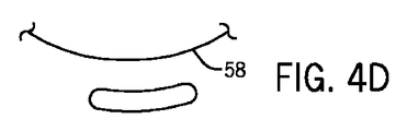
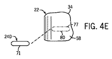
次に図4C乃至図4Eを参照すると、1又は複数の第4のシード24Dは、インプラント22の任意の表面の端の方に取り付けられ、側面71が、内側本体部材32、外側本体部材34、又は拡張リング36の任意の表面にあるシード取付位置77において、インプラント22に取り付けられる。図示の通り、外側本体部材34の外面58は、シード取付位置77を形成する。
Referring now to FIGS. 4C-4E, one or more fourth seeds 24D are attached toward the end of any surface of the
例えば、図4Cに示すように、第4のシード24Dは、外側本体部材34の外面58に直接、取り付けられる。特に、PMMA又は骨セメントなど、オステオバイオロジカルの、又は生物学的適合性の材料を、シード24D及び/又は外面58に塗布し、側面71には、シード取付位置77において外側本体部材34に塗布する。変形例としては、シード24Dは、インプラント22に超音波溶接しても良い。
For example, as shown in FIG. 4C, the fourth seed 24D is attached directly to the
シード24Dは、中心軸線Aが長手軸線に対して実質的に平行に延びるように向けられ、シード24Dの適当な長さが外面58に接着されるようになっている。代わりに又は加えて、図4Dに示すように、1つの側面71は、外面58の曲率に一致するように丸められ、シード24Dは、長手軸線Lに対する任意の向きにて、外面58に取り付けられる。従って、1又は複数の脊柱インプラント21と、インプラント21に取り付けられていないシード24とを含むキットを提供でき、上述したように、インプラント21の様々な取付位置77に取り付けられるべく異なる形状及び/又はサイズに構成されて提供できることを認識されたい。脊柱インプラント21は、代わりに又は加えて、シードを事前に取り付けられて提供されても良い。
The seed 24D is oriented so that the central axis A extends substantially parallel to the longitudinal axis so that a suitable length of the seed 24D is adhered to the
再び図1を参照すると、1又は複数の第5のシード24Eは、インプラント22の内面に取り付けられる。例えば、シード24Eは、骨パッキング開口部52の棚部60上である取付位置77に取り付けられる。シード24Eは、上述した方法で、棚部60に形成された溝部に取り付けられるのに加えて又は代わりに、例えば、PMMA又は骨セメントなど、オステオバイオロジカルであるか、又はその他の生物学的適合性である材料を用いて、取り付けられる。代わりに又は加えて、シード24Eは、インプラント22に超音波溶接しても良い。従って、シード24Eの軸線Aは、インプラント22の長手軸線Lに対して垂直な任意の方向に向けられることを認識されたい。従って、インプラント22が椎骨間の空間に据え付けられるとき、軸線Aは、長手軸線Lに対して垂直な水平面内に向けられ、内側、外側、後方、又は前方の方向に対して、又は斜めに向けられる。
Referring again to FIG. 1, one or more
次に図1及び図4Fを参照すると、インプラント22は、1又は複数のシード取付位置77を、終板キャップ42に形成している。図示の通り、第6のシード24Fは、終板キャップ42のベース45に取り付けられる。シード24Fは、上述した方法で、ベース45に形成された溝部に取り付けられるのに加えて又は代わりに、例えば、PMMA又は骨セメントなど、オステオバイオロジカルであるか、又はその他の生物学的適合性である材料を用いて、取り付けられる。変形例としては、シード24Fは、インプラント22に超音波溶接しても良い。従って、第6のシード24Fの軸線Aは、インプラント22の長手軸線Lに対して垂直である任意の方向に向けられる。従って、インプラント22が椎骨間の空間に据え付けられるとき、軸線Aは、長手軸線Lに対して垂直な水平面内に向けられ、内側、外側、後方、又は前方の方向に対して、又は斜めに向けられる。
Referring now to FIGS. 1 and 4F, the
小線源治療用インプラント20について、拡張可能なインプラント22と関連させて説明したけれども、インプラント20は、人間の脊柱に移植するのに適したあらゆる構造を呈し得ることを認識されたい。さらに、小線源治療用インプラント20は、図示して説明した位置において、6つのタイプの小線源治療用シード24A〜Fを含むものとして、説明したけれども、インプラント20は、1又は複数のタイプのシード24A〜Fを具備し得ることを認識されたい。さらに、1又は複数の、又はすべての、シード24A〜Fは、任意の取付位置77に取り付けられ、又は望むように、インプラント22上の代替的な位置に取り付けられる。
Although the
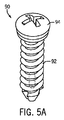
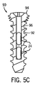
小線源治療用脊柱インプラント20の脊柱インプラント21について、拡張可能な椎骨間インプラント22の1つの実施形態に従って例示される、脊柱インプラント21として構成されたものを図示して説明したけれども、脊柱インプラント21は、所望の任意の変形例による構造を呈することができ、また拡張可能でも堅固でも良い。さらに、インプラント21は、隣接する椎骨間の運動を回復させるために、終板28及び30が互いに対してピボット可能なように構築できることを認識されたい。例えば、図5A乃至図5Dに示すように、脊柱インプラント21は、ねじ90などの小線源治療用骨固定具として提供され、これは、1又は複数のシード24を骨ねじ210の中に搭載されて具備している。変形例としては、骨ねじ90は、放射性核種を一体的に含有しても良い。骨ねじ90は、茎ねじや、前方プレート又は頚椎前方プレートなど、プレートを骨に結合するためのねじ、又はその他の整形外科の骨固定具として提供される。
Although the
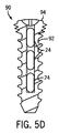
ねじ90は、長手方向に延びたねじ付き軸92と、軸92の近位端に配置された頭部94とを備えている。ねじ90は、チタンなど、任意の適当なインプラント等級の材料から作られる。頭部94は、ねじ付きであり、これは、骨プレートの対応するねじ部と螺合するもので、ねじ90は自己ロック式のねじになっている。軸92の遠位端は、切断縦溝を呈し、ねじ90は、セルフタッピング式のねじになっていても良い。ねじ90は、カニューレ挿入96を含むことができ、頭部94から軸92の中へ長手方向に延在し、軸92の遠位端の付近にて終端している。カニューレ挿入96は、任意の数のシード24を必要に応じて収容し、例えば、1つ、2つ、又は3つを、それぞれ図5A乃至図5Dに示すように収容できる。シード24は、カニューレ挿入96に圧入される。加えて又は代わりに、例えば、PMMA又は骨セメントなど、オステオバイオロジカルであるか、又はその他の生物学的適合性である材料を開口部の中に挿入できる。変形例としては、外殻66は、インプラント22に超音波溶接しても良い。1又は複数のシード24は、好ましくは、骨ねじ90に事前に組み付けられ及び/又は内部に収容される。変形例としては、1又は複数のシード24は、インシトゥーにて、すなわち、手術前に又は手術中に、骨ねじ90に結合される。骨ねじ90は、骨の中に移植され、1又は複数のシード24は続いて骨ねじ90に結合される。
The
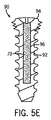
変形例としては、図5Eを参照すると、カニューレ挿入96は、放射性核種70を収容するシード24を含むカニューレ挿入96とは対照的に、上述したタイプの放射性核種70を直接収容しても良い。これに関して、軸92は、放射性核種70を取り巻く外殻を提供し、固定具90は一般に小線源治療用シード24について上述したように構築されるが、骨固定具として構成されることを認識されたい。
Alternatively, referring to FIG. 5E, the
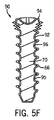
更なる変形例としては、図5Fを参照すると、固定具ないしねじ90は、上述したタイプのうち所望の放射性同位元素から構築しても良い。従って、頭部94及び軸92のうち少なくとも一方又は両方は、アイソトープから構築される。コーティング95は、頭部94及び/又は軸92の外面に適用され、放射性同位元素から形成されて、小線源治療用シード24の外殻66に対して、上述したタイプの外殻66を提供する。
As a further variation, referring to FIG. 5F, the fixture or screw 90 may be constructed from the desired radioisotope of the types described above. Accordingly, at least one or both of the
次に図5Gを参照すると、上述した任意の実施形態に従って構築された固定具90は、変形例としては、ねじの無い軸92を具備し、従って、図5Gに示すように、爪又はピン98を提供するために、滑らかにされ又はうね模様を付けられ又はその他のテクスチャを付けられて、脊柱骨又は軟質組織の中へ望むように直接移植できることをさらに認識されたい。
Referring now to FIG. 5G, a
脊柱インプラント21の例について説明したけれども、小線源治療用インプラント20は、小線源治療用シード24を所望の任意の脊柱インプラントに取り付けられ又は共に提供されて具備し、それらには、任意の望ましい椎骨間インプラント、篭、脊柱ロッドなど、又は骨プレートなどのその他のインプラントが含まれることを認識されたい。1又は複数の脊柱インプラントと、1又は複数のシード24とを含むキットを提供でき、脊柱インプラントであるか、又は脊柱骨又はその他の組織への直接的なものであるかのいずれかの移植位置及び/又は方法に従って、形状及びサイズを定められることを認識されたい。さらに、小線源治療用シード24は、ねじ90、爪98など、完全な脊柱インプラントとして構築でき、又は椎体切除装置、体内スペーサ、脊柱ロッド、椎体内部に挿入すべく構成されたインプラント、その他である。
Although an example of a
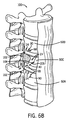
次に図6Aを参照すると、脊柱100は、複数の隣接する椎骨を含み、それらには、下位椎体50A、上位椎体50B、及び隣接する椎体50A及び50Bの間に配置された、悪性の椎体50Cが含まれる。椎間板102は、椎体を隔てている。腫瘍又は転移物104は、椎体50Cの外面に示されるけれども、腫瘍104は椎体50Cの内部に配置されていても良いことを認識されたい。
Referring now to FIG. 6A, the
1つの方法によれば、1又は複数の小線源治療用シード24は、脊柱100に移植されるが、それは、直接に、又は上述したタイプの脊柱インプラント若しくは任意の代替的に構築されたインプラントによって支持されて行われる。図6Bを参照すると、脊柱の腫瘍104を治療する方法は、小線源治療用シード24を直接に又は経皮的に悪性椎体50Cへ移植することを含み、加えて又は代わりに、小線源治療用シード24を隣接する椎体50A〜Bに、又は脊柱100の任意の代替的な位置に移植する。例えば、1又は複数の小線源治療用シード24の外側端面73の片方は、上述した態様によるスパイク形状であり、脊柱100の様々な位置へ直接押し込むことができる。シード24は、完全に脊柱100の中に配置されるか、又は脊柱100から突出して配置される。
According to one method, one or
代わりに又は加えて、1又は複数の開口部106が、脊柱100の様々な位置に形成されて、シード24は、それぞれの開口部106の中に移植しても良い。シード24は、接着せずに開口部106の中に圧入されるか、又は骨セメント若しくは代替的な接着剤108を用いて開口部に接着される。シード24は、セメント注入の前に又は後に、移植される。変形例としては、結合要素は、脊柱100に超音波溶接しても良い。代わりに又は加えて、1又は複数のシード24の側面71は、接着剤又は超音波溶接を用いて、脊柱100に直接結合しても良い。
Alternatively or additionally, one or
変形例としては、小線源治療用シード24は、例えば、別の脊柱インプラントを介して、脊柱100の中に間接的に移植しても良い。1つの実施形態においては、脊柱インプラントは、ねじ90又は爪98を具備し、上述した方法で、1又は複数の小線源治療用シード24を支持させる。ねじ90及び爪98は、従って、所望の位置にて、脊柱100の中に押し込むことができる。頭部94は、脊柱100と面一であるか、又は脊柱100から望むだけ突出する。
Alternatively, the
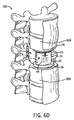
次に図6Cを参照すると、腫瘍104を治療する方法は、脊柱100から腫瘍104を除去する段階を具備している。1つの実施形態においては、椎体切除術が実行され、それにより、腫瘍104をもった椎体50Cの一部分又はすべてが除去されて、隣接する椎骨100A及び100Bの間に配置されるように椎骨間空間110が形成される。代わりに又は加えて、半椎体切除術が実行されて、それにより、椎体の一部分が除去される。図示の実施形態においては、まわりの椎間板物質102もまた除去されている。腫瘍104は除去されたけれども、悪性細胞は脊柱100に取り残されるのが普通であり、特に、腫瘍の外被が傷ついた場合には、悪性細胞が脊柱100の様々な他の位置へと逃げ出して転移することが許容されることを認識されたい。従って、シード24は、上述した脊柱位置に加えて、隣接する椎骨50A及び50Bの椎骨終板51に、直接的に又は間接的に、移植される。
Referring now to FIG. 6C, a method of treating a
図6Dを参照すると、脊柱100に間接的に小線源治療用シードを移植する別の方法は、小線源治療用インプラント20又は任意の代替的な小線源治療用椎骨間インプラントを、椎骨間空間110へ移植することを含む。インプラント22は、表面又は内部に、シード24を据え付けられて有するか、又は、変形例としては、シード24は、インプラントが椎骨間空間110に固定された後で、インプラント20の表面又は内部に据え付けられる。シード24は、インプラント22の表面又は内部の任意の位置に配置され、その向きは、上述したように、1又は複数の悪性細胞を含んでいる見込みのある位置へ向けて、放射線を導くのに適するように定められる。拡張リング36は、必要に応じて操縦され、終板28及び30を椎骨50A及び50Bの終板に係合させる。
Referring to FIG. 6D, another method of indirectly implanting a brachytherapy seed into the
当業者にあっては、広い発明的概念から逸脱せずに、上述した実施形態に変更を施すことができることを認識されたい。従って、本発明は、開示された特定の実施形態に限定されず、本明細書によって定義された本発明の精神及び範囲内において、変形例を包含する意図であることを理解されたい。 Those skilled in the art will recognize that changes can be made to the above-described embodiments without departing from the broad inventive concept. Accordingly, it is to be understood that the invention is not limited to the particular embodiments disclosed, but is intended to encompass modifications within the spirit and scope of the invention as defined by the specification.
Claims (20)
脊柱インプラントであって、長手軸線に沿って延在する本体と、本体の片側の長手端部に配置された上位終板と、本体の反対側の長手端部に配置された下位終板とを具備し、それぞれの終板が、相補的な椎骨終板に係合すべく構成された椎骨係合面を形成している、上記脊柱インプラントと、
インプラント本体に取り付けられた複数の放射線シードであって、小線源治療用インプラントが椎骨間空間に配置されたとき、所望の方向において、放射線を脊柱に向けて導くようになっている、上記複数の放射線シードと、
を備えていることを特徴とする小線源治療用インプラント。 A brachytherapy implant for brachytherapy,
A spinal implant comprising: a body extending along a longitudinal axis; an upper end plate disposed at a longitudinal end on one side of the body; and a lower end plate disposed at a longitudinal end opposite to the body The spinal column implant, wherein each endplate forms a vertebral engagement surface configured to engage a complementary vertebral endplate;
A plurality of radiation seeds attached to the implant body, wherein the plurality of radiation seeds are adapted to direct radiation toward the spinal column in a desired direction when the brachytherapy implant is placed in the intervertebral space. Radiation seeds,
A brachytherapy implant characterized by comprising:
近位端と遠位端とを形成している軸と、軸の近位端に取り付けられた頭部とを備え、軸は、1又は複数の放射線シードを受け入れるように構成されてなるカニューレを形成している、ことを特徴とする小線源治療用インプラント。 A brachytherapy implant,
A cannula comprising a shaft forming a proximal end and a distal end, and a head attached to the proximal end of the shaft, wherein the shaft is configured to receive one or more radiation seeds. A brachytherapy implant characterized in that it is formed.
Applications Claiming Priority (3)
| Application Number | Priority Date | Filing Date | Title |
|---|---|---|---|
| US11823508P | 2008-11-26 | 2008-11-26 | |
| US61/118,235 | 2008-11-26 | ||
| PCT/US2009/065897 WO2010062945A1 (en) | 2008-11-26 | 2009-11-25 | Brachytherapy treatment of the spine with irradiated implants |
Publications (2)
| Publication Number | Publication Date |
|---|---|
| JP2012509721A true JP2012509721A (en) | 2012-04-26 |
| JP2012509721A5 JP2012509721A5 (en) | 2013-01-17 |
Family
ID=41800494
Family Applications (1)
| Application Number | Title | Priority Date | Filing Date |
|---|---|---|---|
| JP2011537739A Abandoned JP2012509721A (en) | 2008-11-26 | 2009-11-25 | Method and apparatus for small dose treatment of spinal column using irradiated implant |
Country Status (6)
| Country | Link |
|---|---|
| US (1) | US20100137674A1 (en) |
| EP (1) | EP2367508A1 (en) |
| JP (1) | JP2012509721A (en) |
| AU (1) | AU2009319814A1 (en) |
| CA (1) | CA2744267A1 (en) |
| WO (1) | WO2010062945A1 (en) |
Families Citing this family (12)
| Publication number | Priority date | Publication date | Assignee | Title |
|---|---|---|---|---|
| US9144627B2 (en) | 2007-09-14 | 2015-09-29 | Exogenesis Corporation | Methods for improving the bioactivity characteristics of a surface and objects with surfaces improved thereby |
| US20100227523A1 (en) * | 2007-09-14 | 2010-09-09 | Exogenesis Corporation | Methods for improving the bioactivity characteristics of a surface and objects with surfaces improved thereby |
| WO2010105102A1 (en) * | 2009-03-11 | 2010-09-16 | Exogenesis Corporation | Methods for improving the bioactivity characteristics of a surface and objects with surfaces improved thereby |
| US20110270395A1 (en) * | 2010-04-28 | 2011-11-03 | Warsaw Orthopedic, Inc. | Device and method for delivering radiation in selected directions |
| US8317673B2 (en) * | 2010-04-30 | 2012-11-27 | Warsaw Othopedic, Inc. | Device and method for controlling emission of radiation |
| US20120010601A1 (en) * | 2010-07-09 | 2012-01-12 | Vanderbilt University | Orthopedic cement and use of same in radiation therapy |
| US8900309B2 (en) * | 2010-08-31 | 2014-12-02 | Meditech Spine, Llc | Spinal implants |
| US9700425B1 (en) | 2011-03-20 | 2017-07-11 | Nuvasive, Inc. | Vertebral body replacement and insertion methods |
| JP2014525817A (en) | 2011-08-22 | 2014-10-02 | エクソジェネシス コーポレーション | Method for improving bioactive characteristics of an object surface and surface improved thereby |
| RU2520682C2 (en) * | 2012-09-04 | 2014-06-27 | Общество с ограниченной ответственностью Экспериментальный научно-исследовательский и методический центр "Моделирующие системы" | Method of treating spinal malignant tumours and spinal metastases of tumours |
| US9968460B2 (en) | 2013-03-15 | 2018-05-15 | Medsmart Innovation Inc. | Dynamic spinal segment replacement |
| CN110215600A (en) * | 2019-05-27 | 2019-09-10 | 北京大学第三医院 | The implantation material of radion can be carried |
Family Cites Families (9)
| Publication number | Priority date | Publication date | Assignee | Title |
|---|---|---|---|---|
| US6120540A (en) * | 1998-01-21 | 2000-09-19 | Apple; Marc G. | Radio prosthesis |
| WO2002009626A1 (en) | 1999-07-26 | 2002-02-07 | Advanced Prosthetic Technologies, Inc. | Improved spinal surgical prosthesis |
| US20030144570A1 (en) * | 1999-11-12 | 2003-07-31 | Angiotech Pharmaceuticals, Inc. | Compositions and methods for treating disease utilizing a combination of radioactive therapy and cell-cycle inhibitors |
| US6558390B2 (en) * | 2000-02-16 | 2003-05-06 | Axiamed, Inc. | Methods and apparatus for performing therapeutic procedures in the spine |
| US20020169354A1 (en) * | 2001-05-10 | 2002-11-14 | Munro John J. | Brachytherapy systems and methods |
| US6695760B1 (en) * | 2002-10-11 | 2004-02-24 | Proxima Therapeutics | Treatment of spinal metastases |
| US6749555B1 (en) * | 2003-02-13 | 2004-06-15 | Proxima Therapeutics, Inc. | System and method for the treatment of spinal metastases |
| US7563281B2 (en) * | 2003-04-03 | 2009-07-21 | Warsaw Orthopedic, Inc. | Apparatus and method for supporting vertebral bodies |
| WO2008024959A2 (en) * | 2006-08-25 | 2008-02-28 | C. R. Bard, Inc. | Therapeutic and directionally dosed implants |
-
2009
- 2009-11-25 WO PCT/US2009/065897 patent/WO2010062945A1/en active Application Filing
- 2009-11-25 AU AU2009319814A patent/AU2009319814A1/en not_active Abandoned
- 2009-11-25 EP EP09764149A patent/EP2367508A1/en not_active Withdrawn
- 2009-11-25 US US12/626,010 patent/US20100137674A1/en not_active Abandoned
- 2009-11-25 JP JP2011537739A patent/JP2012509721A/en not_active Abandoned
- 2009-11-25 CA CA2744267A patent/CA2744267A1/en not_active Abandoned
Also Published As
| Publication number | Publication date |
|---|---|
| US20100137674A1 (en) | 2010-06-03 |
| EP2367508A1 (en) | 2011-09-28 |
| AU2009319814A1 (en) | 2010-06-03 |
| WO2010062945A1 (en) | 2010-06-03 |
| CA2744267A1 (en) | 2010-06-03 |
Similar Documents
| Publication | Publication Date | Title |
|---|---|---|
| JP2012509721A (en) | Method and apparatus for small dose treatment of spinal column using irradiated implant | |
| US11259934B2 (en) | Spine stabilization device, and method and kit for its implantation | |
| JP2011139935A (en) | Brachytherapy method and applicator for treatment of metastatic lesion in load bearing region | |
| EP1549227B1 (en) | Treatment of spinal metastases | |
| US7749150B2 (en) | Device for radiation treatment of proliferative tissue surrounding a cavity in an animal body | |
| US9028499B2 (en) | Bone cutting device | |
| US20130096628A1 (en) | Transcorporeal spinal decompression and repair system | |
| AU2004289269B2 (en) | Brachytherapy apparatus and method for treating a target tissue through an external surface of the tissue | |
| KR101496580B1 (en) | Reconstructing device for surgery of cervical disc | |
| US7288061B2 (en) | Device for implanting a row of radioactive seeds and non-radioactive spacers in an animal body | |
| US20080269540A1 (en) | Seed cartridge adaptor and methods for use therewith |
Legal Events
| Date | Code | Title | Description |
|---|---|---|---|
| A521 | Written amendment |
Free format text: JAPANESE INTERMEDIATE CODE: A523 Effective date: 20121126 |
|
| A621 | Written request for application examination |
Free format text: JAPANESE INTERMEDIATE CODE: A621 Effective date: 20121126 |
|
| A762 | Written abandonment of application |
Free format text: JAPANESE INTERMEDIATE CODE: A762 Effective date: 20130306 |