JP2012509429A - Ocean wave power generator - Google Patents
Ocean wave power generator Download PDFInfo
- Publication number
- JP2012509429A JP2012509429A JP2011536730A JP2011536730A JP2012509429A JP 2012509429 A JP2012509429 A JP 2012509429A JP 2011536730 A JP2011536730 A JP 2011536730A JP 2011536730 A JP2011536730 A JP 2011536730A JP 2012509429 A JP2012509429 A JP 2012509429A
- Authority
- JP
- Japan
- Prior art keywords
- water
- water flow
- flow accelerator
- accelerator
- power generation
- Prior art date
- Legal status (The legal status is an assumption and is not a legal conclusion. Google has not performed a legal analysis and makes no representation as to the accuracy of the status listed.)
- Ceased
Links
Images


Classifications
-
- F—MECHANICAL ENGINEERING; LIGHTING; HEATING; WEAPONS; BLASTING
- F03—MACHINES OR ENGINES FOR LIQUIDS; WIND, SPRING, OR WEIGHT MOTORS; PRODUCING MECHANICAL POWER OR A REACTIVE PROPULSIVE THRUST, NOT OTHERWISE PROVIDED FOR
- F03B—MACHINES OR ENGINES FOR LIQUIDS
- F03B13/00—Adaptations of machines or engines for special use; Combinations of machines or engines with driving or driven apparatus; Power stations or aggregates
- F03B13/12—Adaptations of machines or engines for special use; Combinations of machines or engines with driving or driven apparatus; Power stations or aggregates characterised by using wave or tide energy
- F03B13/14—Adaptations of machines or engines for special use; Combinations of machines or engines with driving or driven apparatus; Power stations or aggregates characterised by using wave or tide energy using wave energy
- F03B13/22—Adaptations of machines or engines for special use; Combinations of machines or engines with driving or driven apparatus; Power stations or aggregates characterised by using wave or tide energy using wave energy using the flow of water resulting from wave movements to drive a motor or turbine
-
- F—MECHANICAL ENGINEERING; LIGHTING; HEATING; WEAPONS; BLASTING
- F03—MACHINES OR ENGINES FOR LIQUIDS; WIND, SPRING, OR WEIGHT MOTORS; PRODUCING MECHANICAL POWER OR A REACTIVE PROPULSIVE THRUST, NOT OTHERWISE PROVIDED FOR
- F03B—MACHINES OR ENGINES FOR LIQUIDS
- F03B13/00—Adaptations of machines or engines for special use; Combinations of machines or engines with driving or driven apparatus; Power stations or aggregates
- F03B13/12—Adaptations of machines or engines for special use; Combinations of machines or engines with driving or driven apparatus; Power stations or aggregates characterised by using wave or tide energy
- F03B13/14—Adaptations of machines or engines for special use; Combinations of machines or engines with driving or driven apparatus; Power stations or aggregates characterised by using wave or tide energy using wave energy
- F03B13/16—Adaptations of machines or engines for special use; Combinations of machines or engines with driving or driven apparatus; Power stations or aggregates characterised by using wave or tide energy using wave energy using the relative movement between a wave-operated member, i.e. a "wom" and another member, i.e. a reaction member or "rem"
- F03B13/18—Adaptations of machines or engines for special use; Combinations of machines or engines with driving or driven apparatus; Power stations or aggregates characterised by using wave or tide energy using wave energy using the relative movement between a wave-operated member, i.e. a "wom" and another member, i.e. a reaction member or "rem" where the other member, i.e. rem is fixed, at least at one point, with respect to the sea bed or shore
-
- F—MECHANICAL ENGINEERING; LIGHTING; HEATING; WEAPONS; BLASTING
- F03—MACHINES OR ENGINES FOR LIQUIDS; WIND, SPRING, OR WEIGHT MOTORS; PRODUCING MECHANICAL POWER OR A REACTIVE PROPULSIVE THRUST, NOT OTHERWISE PROVIDED FOR
- F03B—MACHINES OR ENGINES FOR LIQUIDS
- F03B17/00—Other machines or engines
- F03B17/02—Other machines or engines using hydrostatic thrust
-
- F—MECHANICAL ENGINEERING; LIGHTING; HEATING; WEAPONS; BLASTING
- F05—INDEXING SCHEMES RELATING TO ENGINES OR PUMPS IN VARIOUS SUBCLASSES OF CLASSES F01-F04
- F05B—INDEXING SCHEME RELATING TO WIND, SPRING, WEIGHT, INERTIA OR LIKE MOTORS, TO MACHINES OR ENGINES FOR LIQUIDS COVERED BY SUBCLASSES F03B, F03D AND F03G
- F05B2240/00—Components
- F05B2240/10—Stators
- F05B2240/12—Fluid guiding means, e.g. vanes
-
- Y—GENERAL TAGGING OF NEW TECHNOLOGICAL DEVELOPMENTS; GENERAL TAGGING OF CROSS-SECTIONAL TECHNOLOGIES SPANNING OVER SEVERAL SECTIONS OF THE IPC; TECHNICAL SUBJECTS COVERED BY FORMER USPC CROSS-REFERENCE ART COLLECTIONS [XRACs] AND DIGESTS
- Y02—TECHNOLOGIES OR APPLICATIONS FOR MITIGATION OR ADAPTATION AGAINST CLIMATE CHANGE
- Y02E—REDUCTION OF GREENHOUSE GAS [GHG] EMISSIONS, RELATED TO ENERGY GENERATION, TRANSMISSION OR DISTRIBUTION
- Y02E10/00—Energy generation through renewable energy sources
- Y02E10/20—Hydro energy
-
- Y—GENERAL TAGGING OF NEW TECHNOLOGICAL DEVELOPMENTS; GENERAL TAGGING OF CROSS-SECTIONAL TECHNOLOGIES SPANNING OVER SEVERAL SECTIONS OF THE IPC; TECHNICAL SUBJECTS COVERED BY FORMER USPC CROSS-REFERENCE ART COLLECTIONS [XRACs] AND DIGESTS
- Y02—TECHNOLOGIES OR APPLICATIONS FOR MITIGATION OR ADAPTATION AGAINST CLIMATE CHANGE
- Y02E—REDUCTION OF GREENHOUSE GAS [GHG] EMISSIONS, RELATED TO ENERGY GENERATION, TRANSMISSION OR DISTRIBUTION
- Y02E10/00—Energy generation through renewable energy sources
- Y02E10/30—Energy from the sea, e.g. using wave energy or salinity gradient
Abstract
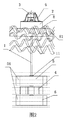
海洋波力発電装置は、浮体(2)と、浮体(2)に固定されている発電機(3)と、水車(4)とを含むものであって、さらに水流加速器(5)を含み、水流加速器(5)と浮体(2)との間には、浮体(2)及び水流加速器(5)に対して回転可能な回転軸(1)が設けられ、回転軸(1)の上端部が浮体(2)を挿通して発電機(3)の回転子に連結され、回転軸(1)の下端部が水流加速器(5)を挿通して水車(4)に固定連結され、水流加速器(5)には、高速水流を形成して水車(4)を一方向に回転させるように推し回すための水流通路(51)が設けられている。
【選択図】 図1The ocean wave power generation device includes a floating body (2), a generator (3) fixed to the floating body (2), and a water turbine (4), and further includes a water flow accelerator (5), Between the water flow accelerator (5) and the floating body (2), there is provided a rotating shaft (1) that can rotate with respect to the floating body (2) and the water flow accelerator (5), and an upper end portion of the rotating shaft (1) is The floating body (2) is inserted and connected to the rotor of the generator (3), the lower end of the rotating shaft (1) is inserted through the water flow accelerator (5) and fixedly connected to the water turbine (4), and the water flow accelerator ( 5) is provided with a water flow passageway (51) for forming a high-speed water flow and forcing the water wheel (4) to rotate in one direction.
[Selection] Figure 1
Description
本発明は、海洋波力発電装置に関するものである。 The present invention relates to an ocean wave power generation device.
海水による発電は、汚染がなく且つ燃料の消費もないという利点がある。そのため、どのように海水の波力を利用して発電するかは、世界各国の海洋工程研究者の研究テーマになっている。わが国は、約18000キロメートルの大陸海岸線を有し、さらにたくさんの島を有しており、海洋のエネルギー資源がとても豊富である。可燃エネルギー資源の減少に伴い、海洋発電技術の研究及び発展は意義深いことである。 Power generation using seawater has the advantage of being free from pollution and consuming no fuel. Therefore, how to generate power using the wave power of seawater has become the research theme of ocean process researchers around the world. Japan has a continental coastline of about 18,000 kilometers, more islands, and abundant marine energy resources. With the decrease of combustible energy resources, research and development of ocean power generation technology is significant.
海洋における波力発電とは、波力発電装置により波の運動エネルギーを電気エネルギーに変換することである。波力発電装置は、波のエネルギーを効率的に吸収できるようにその運転形態が波の上下振動特性に基づいて設計され、安定的な運動メカニズムによって運動エネルギーを取得して発電を行う。波が不安定であることから、従来の発電設備の一つとして、海底(seabed)に設けられるものが知られている。しかし、このような発電設備は、その構造が複雑で、海水による腐食及び波の侵入によって破壊され、使用寿命が短く、施工及びメンテナンスのコストが高いなどの問題がある。また、別の従来発電設備として、海面に浮かれるものが知られている。このような発電設備は、一般的に、水車により発電機の回転子を正方向と逆方向との間で切り替えながら回転させるように駆動することで発電を行う。この場合、発電機の回転子の変向において多くのエネルギーが無駄に消耗されるため、変換効率が低い。また、水車が伝達装置を介してモータの回転子に直接連結されているため、水車の回転スピードが波力の大きさに厳しく制限される。そのため、変換効率を向上させるためには、通常、水車を大きくしなければならない。そうすると、水車と協調する構造が大きくなり、コストが増加し、波力発電の発展に好ましくない。 Wave power generation in the ocean is the conversion of wave kinetic energy into electrical energy by a wave power generator. The wave power generator is designed based on the vertical vibration characteristics of the wave so that the wave energy can be efficiently absorbed, and generates power by acquiring kinetic energy through a stable motion mechanism. Since the waves are unstable, one of the conventional power generation facilities is known that is provided on the seabed. However, such a power generation facility has a problem in that its structure is complicated, it is destroyed by corrosion by seawater and the invasion of waves, the service life is short, and the cost of construction and maintenance is high. Moreover, what floats on the sea surface is known as another conventional power generation equipment. Such a power generation facility generally generates power by driving a generator rotor so as to rotate while switching between a forward direction and a reverse direction. In this case, since a lot of energy is wasted in the turning of the rotor of the generator, the conversion efficiency is low. Further, since the water wheel is directly connected to the rotor of the motor via the transmission device, the rotation speed of the water wheel is severely limited to the magnitude of wave power. Therefore, in order to improve the conversion efficiency, usually, the water turbine must be enlarged. If it does so, the structure which cooperates with a water turbine will become large, cost will increase, and it is not preferable for development of wave power generation.
本発明の目的は、動力設備が海水面以下に設けられ、発電設備が海水面に浮かれるように形成された、高発電効率を有する海洋波力発電装置を提供することにある。 An object of the present invention is to provide a marine wave power generation apparatus having high power generation efficiency, in which power equipment is provided below the sea level and the power generation equipment is formed to float on the sea level.
上記の目的を実現するために、本発明は、以下のように構成する。
海洋波力発電装置は、浮体と、浮体に固定された発電機と、水車とを含むものであって、さらに水流加速器を含み、前記水流加速器と前記浮体との間には、浮体及び水流加速器に対して回転可能な回転軸が設けられ、回転軸の上端が浮体を挿通して前記発電機の回転子に連結され、前記回転軸の下端が前記水流加速器を挿通して前記水車に固定連結され、前記水流加速器には、高速水流を形成して水車を一方向に回転させるように推し回すための水流通路が設けられていることを特徴とする。
In order to achieve the above object, the present invention is configured as follows.
The ocean wave power generation apparatus includes a floating body, a generator fixed to the floating body, and a water wheel, and further includes a water flow accelerator, and the floating body and the water flow accelerator are interposed between the water flow accelerator and the floating body. A rotating shaft that is rotatable with respect to the rotating shaft, an upper end of the rotating shaft is inserted through a floating body and connected to the rotor of the generator, and a lower end of the rotating shaft is inserted through the water flow accelerator and fixedly connected to the water turbine. The water flow accelerator is provided with a water flow passage for forming a high-speed water flow to rotate the water wheel in one direction.
上記のような海洋波力発電装置において、前記水流通路は、螺旋状をなし、その断面積が入水端から出水端に向けて漸減することを特徴とする。
上記のような海洋波力発電装置において、前記水流加速器は、前記水車の上方に位置し、水流通路の入水端において水流加速器の上端面には入水口が形成され、水流通路の出水端において水流加速器の下端面には出水口が形成され、出水口が前記水流加速器の中心からずれており、前記入水口の面積が前記出水口の面積よりも大きいことを特徴とする。
In the ocean wave power generation apparatus as described above, the water flow passage has a spiral shape, and its cross-sectional area gradually decreases from the water inlet end toward the water outlet end.
In the ocean wave power generation apparatus as described above, the water flow accelerator is located above the water wheel, a water inlet is formed at an upper end surface of the water flow accelerator at a water inlet end of the water flow passage, and a water flow is formed at a water outlet end of the water flow passage. A water outlet is formed at the lower end surface of the accelerator, the water outlet is displaced from the center of the water flow accelerator, and the area of the water inlet is larger than the area of the water outlet.
上記のような海洋波力発電装置において、前記水車の下方にさらに第2水流加速器が設けられ、前記回転軸の下端が下に延伸して第2水流加速器を挿通し、第2水流加速器には、高速水流を形成して前記水車を同じ方向に回転させるように押し回すための通路が設けられていることを特徴とする。 In the ocean wave power generation apparatus as described above, a second water flow accelerator is further provided below the water wheel, a lower end of the rotating shaft extends downward, and the second water flow accelerator is inserted. A passage for forming a high-speed water flow and pushing the water wheel to rotate in the same direction is provided.
上記のような海洋波力発電装置において、前記通路は、螺旋状をなし、その断面積が入水端から出水端に向けて漸減し、通路の入水端において第2水流加速器の上端面には第2入水口が形成され、通路の出水端において第2水流加速器の下端面には第2出水口が形成され、第2出水口は前記第2水流加速器の中心からずれており、前記第2入水口の面積が前記出水口の面積よりも大きいことを特徴とする。 In the ocean wave power generation device as described above, the passage has a spiral shape, and its cross-sectional area gradually decreases from the water inlet end toward the water outlet end, and at the water inlet end of the passage, 2 water inlets are formed, a second water outlet is formed at the lower end surface of the second water flow accelerator at the water outlet end of the passage, and the second water outlet is displaced from the center of the second water flow accelerator. The area of the water outlet is larger than the area of the water outlet.
上記のような海洋波力発電装置において、前記回転軸は、前記水流加速器及び第2水流加速器にそれぞれ回転可能に接続され、回転軸には、水流加速器及び第2水流加速器の軸方向における移動を防止するための位置決めフランジが設けられ、水流加速器及び第2水流加速器の外周にはこれらの回転を防止する垂直バッフルプレートがそれぞれ設けられていることを特徴とする。 In the ocean wave power generation device as described above, the rotation shaft is rotatably connected to the water flow accelerator and the second water flow accelerator, respectively, and the rotation shaft is moved in the axial direction of the water flow accelerator and the second water flow accelerator. Positioning flanges are provided to prevent this, and vertical baffle plates are provided on the outer peripheries of the water flow accelerator and the second water flow accelerator to prevent their rotation.
上記のような海洋波力発電装置において、前記浮体の下方には上方に向けて開口された貯水器が設けられ、貯水器と浮体とが固定接続され、貯水器の外周に垂直板が設けられ、前記回転軸は前記水流加速器及び第2水流加速器を貫通し、水流加速器及び第2水流加速器は接続片により前記貯水器に固定連結されていることを特徴とする。 In the ocean wave power generation apparatus as described above, a reservoir that opens upward is provided below the floating body, the reservoir and the floating body are fixedly connected, and a vertical plate is provided on the outer periphery of the reservoir. The rotating shaft passes through the water flow accelerator and the second water flow accelerator, and the water flow accelerator and the second water flow accelerator are fixedly connected to the water reservoir by a connecting piece.
上記のような海洋波力発電装置において、前記浮体は、水面に浮かれるのであって、上挟持板と、下挟持板と、上挟持板と下挟持板との間に固定された浮盤とを含み、上挟持板、下挟持板及び浮盤は一体に固定接続され、下挟持板の下側に複数枚の接続板が設けられ、接続板の下端が前記貯水器の底部に固定連結されていることを特徴とする。 In the ocean wave power generation apparatus as described above, the floating body is floated on the water surface, and includes an upper sandwiching plate, a lower sandwiching plate, and a floating base fixed between the upper sandwiching plate and the lower sandwiching plate. The upper clamping plate, the lower clamping plate and the floating plate are integrally fixedly connected, a plurality of connection plates are provided below the lower clamping plate, and the lower end of the connection plate is fixedly connected to the bottom of the reservoir. It is characterized by being.
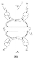
上記のような海洋波力発電装置において、前記水車には複数の羽根が設けられ、前記羽根は、平滑な円弧状片であり、前記水車の外周に沿って均一に配置されていることを特徴とする。 In the ocean wave power generation device as described above, the water turbine is provided with a plurality of blades, the blades are smooth arc-shaped pieces, and are uniformly arranged along the outer periphery of the water wheel. And
本発明によれば、以下のような効果が得られる。
1、回転軸に水車が固定されており、該水車が波浪の波動に従って上昇する場合、水車の上方に位置する水流加速器において形成される下向けの高速水流によって水車を時計方向に回転させることとした。また、水車が波に従って下降する場合、水車の下方に位置する第2水流加速器において形成される上向けの高速水流によって水車を上記と同じ方向に回転させる。これにより、水車の上昇時及び下降時の回転方向の不一致によるエネルギーの損失を回避できる。水流加速器の水流通路及び第2水流加速器の通路は、それぞれ螺旋状をなし、且つその断面積が入水端から出水端に向けて漸減する。2つの水流加速器が上へ又は下へ移動する際、その入水量と出水量が同じであるため、出水口の流速が入水口の流速よりも速くなり、水車に対する水流の衝突力が大きくなる。これにより、変換効率が向上する。
According to the present invention, the following effects can be obtained.
1. When a water turbine is fixed to the rotating shaft, and the water turbine rises according to the wave of waves, the water turbine is rotated clockwise by a downward high-speed water flow formed in a water flow accelerator located above the water wheel. did. Moreover, when a water turbine descend | falls according to a wave, a water turbine is rotated in the same direction as the above by the upward high-speed water flow formed in the 2nd water flow accelerator located under a water wheel. Thereby, it is possible to avoid energy loss due to a mismatch in the rotation direction when the water turbine is raised and lowered. The water flow passage of the water flow accelerator and the flow passage of the second water flow accelerator each have a spiral shape, and the cross-sectional area gradually decreases from the water inlet end toward the water outlet end. When the two water flow accelerators move up or down, the water flow rate is the same as the water flow rate because the water flow rate is the same as the water flow rate, and the collision force of the water flow against the water turbine is increased. Thereby, conversion efficiency improves.
2、浮体の下方には上方に向けて開口された貯水器が設けられている。浮体及び貯水器が波に従って上昇する場合、浮体は上方への浮力を受ける。該浮力により水流加速器が静水層において上方に速やかに移動して水車を時計方向に回転させるように押し回すことによって、発電を行う。波浪がピークに達した場合、浮体及び貯水器は、水車からの反作用力を受けるため、波浪とともに下降しない。その場合、貯水器内の水の位置エネルギーが第2水流加速器を下方に移動させる運動エネルギーに変換されることで、発電效率が向上する。 2. Below the floating body, a water reservoir opened upward is provided. When the floating body and the reservoir rise according to the wave, the floating body receives upward buoyancy. Due to the buoyancy, the water flow accelerator moves quickly in the still water layer and pushes the water wheel to rotate clockwise to generate power. When the wave reaches a peak, the floating body and the water reservoir are not lowered with the wave because the reaction force from the water turbine is received. In this case, the power generation efficiency is improved by converting the potential energy of the water in the water reservoir into kinetic energy that moves the second water flow accelerator downward.
3、水流加速器に2つ以上の水流通路を設けたり、第2水流加速器に2つ以上の通路を設けたりすることにより、変換効率を更に向上できる。水流通路又は通路の増加のほかに、回転軸の下部において所定の距離を置いて水流加速器、水車及び第2第2水流加速器からなる複数組の発電動力機構を取付けることにより、本発明の変換効率を大幅に向上できる。 3. The conversion efficiency can be further improved by providing two or more water passages in the water flow accelerator or providing two or more water passages in the second water flow accelerator. In addition to the water flow passage or the increase in the number of passages, the conversion efficiency of the present invention can be improved by attaching a plurality of sets of power generation power mechanisms including a water flow accelerator, a water wheel, and a second second water flow accelerator at a predetermined distance below the rotating shaft. Can be greatly improved.
4、浮体が水面に浮かれ、回転軸及び発電機が直立に置かれるため、動力を提供する水車、水流加速器及び第2水流加速器が海水面以下に位置し、発電機が海水面に浮かれる。したがって、発電機及びその取付部材が海水に侵食されることを防止でき、使用寿命を延長できる。 4. Since the floating body floats on the water surface and the rotating shaft and the generator are placed upright, the water turbine, the water flow accelerator and the second water flow accelerator that provide power are positioned below the sea water surface, and the generator floats on the sea water surface. Therefore, the generator and its mounting member can be prevented from being eroded by seawater, and the service life can be extended.
以下、本発明の実施形態を図面に従って詳しく説明する。
図に示すように、本発明に係る海洋波力発電装置は、浮体2と、発電機3と、水車4と、水流加速器5とを含んでいる。発電機3は、浮体2に固定され、浮体2の下方には、上方に向けて開口する貯水器8が設けられている。貯水器8は、浮体2に固定接続され、貯水器8の外周にはその回転を防止する垂直板81が設けられている。水流加速器5と浮体2との間には、浮体2及び水流加速器5に対して回転可能な回転軸1が設けられている。回転軸1は、その上端が浮体2を貫通して発電機3の回転子に連結され、その下端が水流加速器5を貫通して水車4に固定連結されている。水流加速器5には、高速水流を形成して水車4を一方向に回転させるように推し回すための水流通路51が設けられている。水車4が回転軸1を介して発電機3を駆動して発電を行う場合、発電機3は回転軸1の回転方向と同方向の駆動力を受ける。そして、貯水器8の外周に形成された垂直板81が海水に浸され、発電機3の受けられた駆動力が貯水器8に伝達される。垂直板81が回転しようとすると、海水による抵抗に打ち勝たなければならない。しかし、垂直板81の回転の際に発生する抵抗は、発電機3が発電の際に受ける駆動力よりも遥かに大きくなるように設計されている。このようにして、発電機3が発電する際に、台座30が回転しないことを確保できる。
As shown in the figure, the ocean wave power generation device according to the present invention includes a floating
本発明の3つの実施例において、回転軸1は、直立に設けられた長ロッドである。水流加速器5は、直立に設けられた円柱体である。浮体2は、揺動中において常に水面に浮かれるような大きさを有する。浮体2は、上挟持板21と、下挟持板23と、挟持板21と下挟持板23との間に固定された浮盤22とを含み、上挟持板21、下挟持板23及び浮盤22が一体に固定接続されている。下挟持板23の下側には、複数枚の接続板24が設けられ、接続板24の下端が貯水器8の底部に固定連結されている。浮体2の上挟持板21の上端には、支持枠9が設けられ、支持枠9の一端が上挟持板21に固定連結され、支持枠9の他端が発電機3の台座30に固定連結されている。
In the three embodiments of the present invention, the
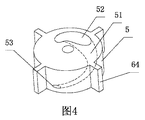
水車4は、その外周方向に沿って複数の羽根41が設けられ、当該羽根41が平滑な円弧状片に設計されている。水流加速器5は、水車4の上方に位置している。水流通路51は、螺旋状をなし、その断面積が入水端から出水端に向けて漸減する。水流通路51の入水端において水流加速器5の上端面には入水口52が形成され、水流通路51の出水端において水流加速器5の下端面には出水口53が形成され、当該出水口53が水流加速器5の中心から外れている。また、水流通路51は、出水口53よりも入水口52が遥かに大きい。入水口52の面積が出水口53の面積よりも大きく、且つ水流通路5の断面積が入水口52から出水口53に向けて漸減するように形成されているため、水流通路5内の海水が出水口53において高流速の水流を形成できる。高流速の水流が水車4の羽根41に衝突することにより回転軸1を時計方向に回転させるように駆動することで、発電が行われる。より高速の水流を形成するために、入水口52の面積が出水口53の面積よりも大幅に大きくなるように、例えば入水口52の面積が出水口53の面積の3−10倍、ひいてはさらに大きくなるようにしてもよい。
The
水車4の下方には、第2水流加速器6が設けられ、回転軸1の下端が下方に延びて第2水流加速器6を挿通する。第2水流加速器6は、直立に設けられた円柱体である。第2水流加速器6には、高速水流を形成して水車4を同じ方向に回転させるように駆動するための通路61が設けられている。通路61は、螺旋状をなし、その断面積が入水端から出水端に向けて漸減する。通路61の入水端において第2水流加速器6の下端面には第2入水口62が形成され、通路61の出水端において第2水流加速器6の上端面には第2出水口63が形成され、当該第2出水口63が第2水流加速器6の中心から外れている。また、通路61は、第2入水口62の面積が第2出水口63の面積よりも大きい。第2入水口62の面積が第2出水口63の面積よりも大きく、且つ通路61の断面積が漸減するように形成されているため、通路61内の海水が第2出水口63において高流速の水流を形成できる。当該高流速の水流が水車4の羽根41に衝突することにより回転軸1を時計方向に回転させるように駆動することで、発電が行われる。より高速の水流を形成するために、第2入水口62の面積が第2出水口63の面積よりも大幅に大きくなるように、例えば第2入水口62の面積が第2出水口63の面積3−10倍、ひいてはさらに大きくなるようにしてもよい。
A second
図1〜図7に示すように、実施例1では、水流加速器5に一つの水流通路51が設けられ、第2水流加速器6に一つの通路61が設けられている。回転軸1は、水流加速器5及び第2水流加速器6にそれぞれ回転可能に接続されている。回転軸1には、水流加速器5及び第2水流加速器の軸方向における移動を防止するための位置決めフランジ11が設けられている。このようにして、回転軸1は、動作中において水流加速器5及び第2水流加速器6に対して回転でき、且つ水流加速器5及び第2水流加速器6とともに上下移動できる。また、水流加速器5及び第2水流加速器6の外周にはこれらの回転を防止するための垂直バッフルプレート64がそれぞれ設けられている。垂直バッフルプレート64の作用は、水流加速器5及び第2水流加速器6内で高速水流の反作用力による影響を抵抗することで、水流加速器5及び第2水流加速器6の回転によって変換効率が影響されることを回避することにある。
As shown in FIGS. 1 to 7, in the first embodiment, one
本発明の実施例1に係る装置の動作手順は以下のとおりである。
第1ステップにおいて、浮体2が波に従って上方向に移動する場合、水車4は静水層において上昇移動し、海水が水流加速器5の入水口52、水流通路51及び出水口53を経由した後、出水口53において入水口52での水流速度よりも遥かに速い高速水流を形成する。そして、水流が高速で水車4に衝突して回転軸1を時計方向に回転させるように駆動することで、第1ステップの発電が行われる。そのとき、第2水流加速器6は動作しない状態にある。上昇の際、浮体2の上方向への移動は不均速運動であり、ピークに達した時、水流加速器5が静水層において上方向への移動を停止するが、水車4は慣性によって回転し続ける。その時、回転軸1も回転し続ける。その後、浮体2及びその下方に位置する貯水器8、並びに貯水器8内に貯留された海水は、重力の作用で波に従って下方向へ移動して、第2ステップに入る。
The operation procedure of the apparatus according to the first embodiment of the present invention is as follows.
In the first step, when the floating
第2ステップにおいて、水流加速器5は動作しない状態にある。海水は、第2水流加速器6の第2入水口62、通路61及び第2出水口63を経由した後、第2出水口63において第2入水口62での水流速度よりも遥かに速い高速水流を形成する。そして、水流が高速で水車4に衝突して回転軸を時計方向に回転させるように駆動することで、第2ステップの発電が行われる。下降の際、浮体2の下方向への移動は不均速運動であり、トラフに達した時、第2水流加速器6が静水層において下方向への移動を停止するが、水車4は慣性によって回転し続ける。その後、本発明の装置は、波に従って再び上方向に移動することで、周期的に発電を行う。前述したように、本発明の装置は、上下移動する際に回転軸1が常に時計方向に回転するため、回転軸の正逆両方向への回転に起因するエネルギー損失を回避できる。
In the second step, the
海洋の表面から所定の深さまでの部分は、波浪運動によりその中の物質もともに浮動するため、「波動層」と呼ばれる。また、更に深い部分は、海水が静止状態にあるため、「静水層」と呼ばれる。本発明の装置が海洋で動作する場合、浮体2は、海水面、即ち波動層に位置しており、波浪の波動に従って上下移動し、水車4、水流加速器5及び第2水流加速器6は、静止層にある。こうして、本発明の装置は、海水の波運動の特徴により波力エネルギーから機械エネルギーへ変換でき、さらに機械エネルギーを電気エネルギーに変換できる。また、浮体2が水面に浮かれ、回転軸1及び発電機3が直立に設けられているため、動力を供給する水車4、水流加速器5及び第2水流加速器6が海水面以下に位置するとともに、発電機3が海水面に浮かれる。これにより、発電機3及びその取付部材が海水に侵食されることを回避でき、使用寿命を延長できる。
The part from the surface of the ocean to a certain depth is called the “wave layer” because the material in it floats together with the wave motion. Further, the deeper portion is called a “hydrostatic layer” because the seawater is still. When the apparatus of the present invention operates in the ocean, the floating
実際に使用する場合、回転軸1を常に時計方向に回転させるほか、水流通路51或いは通路61の螺旋方向を変えることによって回転軸1を常に反時計方向に回転させてもよい。それらの動作原理は同様である。また、実際に使用する場合は、所定面積を有する海面に本発明に係る装置を複数個設置した後、全ての装置によって発生した電気量を収集して海岸へ伝送し、さらに電力品質加工及び処理を行う。各装置からの電気エネルギーの収集は、浮枠によって行われる。電気エネルギーの収集において、それぞれ電気エネルギー処理を行ってから収集してもよく、収集してから一括的に電気エネルギー処理を行ってもよい。また、近くで海水を電解して水素を生成し、生成した水素を海岸へ輸送してもよい。
When actually used, the
図8及び図9に示すように、実施例2では、水流加速器5に、2つの水流通路51と、各水流通路51に対応する入水口52及び出水口53とを設けることで、変換効率をさらに向上させる。また、第2水流加速器6にも、2つの通路61と、各通路61に対応する二つの第2入水口62及び第2出水口63を設けることで、変換効率をさらに向上させる。回転軸1は、水流加速器5及び第2水流加速器6に回転可能に接続され、回転軸1には、水流加速器5及び第2水流加速器6が軸方向に沿って移動することを防止するための位置決めフランジ11が設けられている。こうして、回転軸1は、動作中に水流加速器5及び第2水流加速器6に対して回転可能であり、水流加速器5及び第2水流加速器6とともに上下移動できる。また、水流加速器5及び第2水流加速器6の外周にはこれらの回転を防止する垂直バッフルプレート64がそれぞれ設けられている。実施例2において、水流通路51或いは通路61の増加の他、回転軸1の下部に間隔を置いて水流加速器5、水車4及び第2水流加速器6からなる複数組の発電動力機構(図示せず)を取付けることによっても、変換効率を向上できる。
As shown in FIGS. 8 and 9, in the second embodiment, the
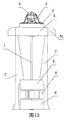
図10に示す実施例3のように、水流加速器5及び第2水流加速器6に一つ或いは複数の水流通路(図示せず)を設けてもよい。回転軸1は、水流加速器5及び第2水流加速器6を回転可能に挿通しており、水流加速器5と第2水流加速器6とは、接続片7を介して前記貯水器8に固定連結されている。貯水器8は、その外周に位置する垂直板81の抵抗作用により回転しないため、水流加速器5及び第2水流加速器6も回転しない。したがって、水流加速器5及び第2水流加速器6の回転により変換効率が影響されることを回避できる。
As in the third embodiment shown in FIG. 10, the
Claims (9)
さらに水流加速器(5)を含み、前記水流加速器(5)と前記浮体(2)との間には、浮体(2)及び水流加速器(5)に対して回転可能な回転軸(1)が設けられ、回転軸(1)の上端部が浮体(2)を挿通して前記発電機(3)の回転子に連結され、前記回転軸(1)の下端部が前記水流加速器(5)を挿通して前記水車(4)に固定連結され、前記水流加速器(5)には、高速水流を形成して水車(4)を一方向に回転させるように推し回すための水流通路(51)が設けられていることを特徴とする海洋波力発電装置。 An ocean wave power generation device including a floating body (2), a generator (3) fixed to the floating body (2), and a water turbine (4),
Furthermore, a rotating shaft (1) that includes a water accelerator (5) and is rotatable with respect to the floating body (2) and the water accelerator (5) is provided between the water accelerator (5) and the floating body (2). The upper end of the rotating shaft (1) is inserted through the floating body (2) and connected to the rotor of the generator (3), and the lower end of the rotating shaft (1) is inserted through the water flow accelerator (5). The water flow accelerator (5) is provided with a water flow passage (51) for forming a high-speed water flow and rotating the water wheel (4) to rotate in one direction. The ocean wave power generation device characterized by being made.
Applications Claiming Priority (3)
| Application Number | Priority Date | Filing Date | Title |
|---|---|---|---|
| CN2008102194311A CN101737234B (en) | 2008-11-21 | 2008-11-21 | Device for ocean wave energy power generation |
| CN200810219431.1 | 2008-11-21 | ||
| PCT/CN2009/074934 WO2010057419A1 (en) | 2008-11-21 | 2009-11-13 | Oceanic wave electric-generating equipment |
Publications (1)
| Publication Number | Publication Date |
|---|---|
| JP2012509429A true JP2012509429A (en) | 2012-04-19 |
Family
ID=42197839
Family Applications (1)
| Application Number | Title | Priority Date | Filing Date |
|---|---|---|---|
| JP2011536730A Ceased JP2012509429A (en) | 2008-11-21 | 2009-11-13 | Ocean wave power generator |
Country Status (11)
| Country | Link |
|---|---|
| US (1) | US8450869B2 (en) |
| EP (1) | EP2351930A4 (en) |
| JP (1) | JP2012509429A (en) |
| KR (1) | KR101254869B1 (en) |
| CN (1) | CN101737234B (en) |
| AU (1) | AU2009317697B2 (en) |
| BR (1) | BRPI0914087A2 (en) |
| CA (1) | CA2743984A1 (en) |
| MY (1) | MY158360A (en) |
| RU (1) | RU2470179C1 (en) |
| WO (1) | WO2010057419A1 (en) |
Cited By (1)
| Publication number | Priority date | Publication date | Assignee | Title |
|---|---|---|---|---|
| JP2017129151A (en) * | 2012-06-13 | 2017-07-27 | 木村 光照 | Wave power generating system, transmission body and rotation conversion part used in wave power generating system |
Families Citing this family (24)
| Publication number | Priority date | Publication date | Assignee | Title |
|---|---|---|---|---|
| CN102434370B (en) * | 2010-09-29 | 2013-12-25 | 中山市创想模型设计有限公司 | Hydrostatic-layer wave energy power generating device |
| CN102434356B (en) * | 2010-09-29 | 2015-03-25 | 中山市创想模型设计有限公司 | Tidal wave energy power generation device |
| CN102562422A (en) * | 2010-12-24 | 2012-07-11 | 孙毅 | Wave energy conversion method |
| CN102720628B (en) * | 2012-06-15 | 2015-03-25 | 郑贵林 | Method for quickened extraction of wave energy based on compressible fluid and two-way water turbine for realizing method |
| CN103511162B (en) * | 2012-06-19 | 2017-02-08 | 集美大学 | Double-spiral rotor type marine energy conversion system |
| ES2495216B1 (en) * | 2013-03-12 | 2015-09-17 | Marc GARRETA CUBO | Hydraulic turbine |
| KR101504866B1 (en) * | 2014-02-18 | 2015-03-23 | 포항공과대학교 산학협력단 | Wave-power generating apparatus |
| CN104976017B (en) * | 2014-04-11 | 2017-07-11 | 王希章 | A kind of water motor |
| KR101505781B1 (en) * | 2014-07-03 | 2015-03-26 | 포항공과대학교 산학협력단 | Position control type wave power generating apparatus |
| CN104481788A (en) * | 2014-09-29 | 2015-04-01 | 华北电力大学(保定) | Bidirectional double-channel and double-rotor sea wave impact power generating device |
| WO2016129786A1 (en) * | 2015-02-10 | 2016-08-18 | 주식회사 인진 | Prefabricated buoy |
| CN104775978B (en) * | 2015-03-18 | 2017-03-01 | 李质玉 | Goalpost ocean wave generator |
| CN105840392B (en) * | 2016-06-15 | 2017-12-22 | 王德辉 | A kind of Floating Tidal TRT |
| CN109026512B (en) * | 2016-11-25 | 2020-12-22 | 福建省新能海上风电研发中心有限公司 | Wind energy and ocean energy comprehensive power generation device capable of reducing resistance |
| RU2655182C1 (en) * | 2017-02-08 | 2018-05-24 | ФЕДЕРАЛЬНОЕ ГОСУДАРСТВЕННОЕ КАЗЕННОЕ ВОЕННОЕ ОБРАЗОВАТЕЛЬНОЕ УЧРЕЖДЕНИЕ ВЫСШЕГО ОБРАЗОВАНИЯ "Военная академия Ракетных войск стратегического назначения имени Петра Великого" МИНИСТЕРСТВА ОБОРОНЫ РОССИЙСКОЙ ФЕДЕРАЦИИ | Electric power installation for self-contained power supply of marine devices in areas with a complex ice situation |
| CN107829880A (en) * | 2017-10-31 | 2018-03-23 | 浙江海洋大学 | A kind of wind energy, tidal current energy generating equipment |
| CN107816412A (en) * | 2017-10-31 | 2018-03-20 | 浙江海洋大学 | A kind of tidal generating set and ship |
| CN108087189A (en) * | 2017-12-14 | 2018-05-29 | 王彦程 | A kind of two-way Wave power generation device based on wave fluctuation momentum |
| CN108443051B (en) * | 2018-03-20 | 2020-09-11 | 天津工业大学 | Novel high-efficient sealed wave energy power generation device |
| CN110195681A (en) * | 2019-05-23 | 2019-09-03 | 贵州航天天马机电科技有限公司 | A kind of two-way hydraulic turbine of ocean power generation device |
| CN110671257B (en) * | 2019-10-12 | 2020-11-24 | 浙江海洋大学 | Offshore power generation device |
| CN111219286B (en) * | 2020-01-16 | 2020-12-22 | 兰州理工大学 | Floating type hydraulic turbine set |
| CN112709668A (en) * | 2020-12-28 | 2021-04-27 | 南京坛欣旭贸易有限公司 | New energy utilization device |
| CN114483420B (en) * | 2022-02-21 | 2023-08-18 | 山东环科环保科技有限公司 | Flow pushing device using water pump residual pressure as power |
Citations (6)
| Publication number | Priority date | Publication date | Assignee | Title |
|---|---|---|---|---|
| JPS5770959A (en) * | 1980-10-20 | 1982-05-01 | Ryokichi Umagami | Underwater vanes for wave force power generation |
| JPH0323384A (en) * | 1989-06-20 | 1991-01-31 | Katsuyuki Kawaguchi | Floating body type wave pump |
| JPH0828429A (en) * | 1994-07-13 | 1996-01-30 | Akira Narisada | Driving force generating method and hydraulic booster engine |
| JPH10159704A (en) * | 1996-12-03 | 1998-06-16 | Taiyo Plant Kk | Wave force pump activated by energy of wave |
| JP2007016770A (en) * | 2005-06-06 | 2007-01-25 | Masaharu Uchida | Power generation device using fluid energy |
| WO2008101381A1 (en) * | 2007-01-27 | 2008-08-28 | Zhihui Deng | A method and device of using oceanic wave to generate electricity |
Family Cites Families (19)
| Publication number | Priority date | Publication date | Assignee | Title |
|---|---|---|---|---|
| US4214712A (en) * | 1977-04-28 | 1980-07-29 | Hoorn Jacques J B Van | Micro-mill-mixer |
| US4447740A (en) * | 1979-11-08 | 1984-05-08 | Heck Louis J | Wave responsive generator |
| FR2606835B1 (en) * | 1986-11-17 | 1991-04-19 | Onde Marcel | INSTALLATION FOR TRANSFORMING CINETIC ENERGY OF WAVES INTO MECHANICAL ENERGY |
| RU1822467C (en) * | 1990-06-26 | 1993-06-15 | В.Ф.Раковский | Hydroelectric plant |
| FR2671048A1 (en) * | 1991-01-02 | 1992-07-03 | Jean Bernard Chas | PROPELLER ATTACHED IN ITS HOLLOW JET. |
| DK171714B1 (en) * | 1994-01-18 | 1997-04-01 | Tage Stenberg Basse | Wave-driven power station |
| GB9804770D0 (en) * | 1998-03-07 | 1998-04-29 | Engineering Business Ltd | Apparatus for extracting power from moving water |
| GB2390876A (en) * | 2002-05-23 | 2004-01-21 | Keith White | Wave energy electricity generator |
| US20030227173A1 (en) * | 2002-06-07 | 2003-12-11 | Vladislav Gorshkov | Floating electrical power production utilizing energy of sea waves |
| UA74414C2 (en) * | 2003-08-14 | 2005-12-15 | Віктор Олексійович Слободюк | Sea electric power plant “energotriada” |
| US7329964B2 (en) * | 2005-03-10 | 2008-02-12 | Jae-Hong Park | Compact hydropower generator adopting multiple rotary drums |
| CN1737362A (en) * | 2005-09-01 | 2006-02-22 | 李德强 | Impulse and enclosed type wave energy gatherer |
| JP5143825B2 (en) * | 2006-05-01 | 2013-02-13 | オーシャン パワー テクノロジーズ,インク. | Improved wave energy converter (WEC) with heave plate |
| CN201021651Y (en) * | 2007-01-27 | 2008-02-13 | 邓志辉 | A device for power generation based on ocean wave energy |
| CN101240768B (en) * | 2007-02-09 | 2010-09-01 | 胡伟 | Generating set utilizing fluid as dynamic power |
| ES2304099B1 (en) * | 2007-02-20 | 2009-06-04 | Julio De La Cruz Blazquez | INSTALLATION TO PRODUCE ELECTRICAL ENERGY FROM THE WAVES OF THE SEA BY THE BASIC IMPULSION METHOD. |
| US8084873B2 (en) * | 2008-01-07 | 2011-12-27 | Carter Richard W | Induced surface flow wave energy converter |
| CN101737362A (en) * | 2008-11-19 | 2010-06-16 | 沈阳耐蚀合金泵股份有限公司 | Self-control fluid jet and drainage lift pump |
| CN110123083A (en) * | 2019-05-10 | 2019-08-16 | 班岚 | A kind of cartoon Revolving display rack |
-
2008
- 2008-11-21 CN CN2008102194311A patent/CN101737234B/en not_active Expired - Fee Related
-
2009
- 2009-11-13 KR KR1020117008777A patent/KR101254869B1/en not_active IP Right Cessation
- 2009-11-13 JP JP2011536730A patent/JP2012509429A/en not_active Ceased
- 2009-11-13 MY MYPI2011001722A patent/MY158360A/en unknown
- 2009-11-13 BR BRPI0914087A patent/BRPI0914087A2/en not_active IP Right Cessation
- 2009-11-13 RU RU2011117041/06A patent/RU2470179C1/en not_active IP Right Cessation
- 2009-11-13 WO PCT/CN2009/074934 patent/WO2010057419A1/en active Application Filing
- 2009-11-13 AU AU2009317697A patent/AU2009317697B2/en not_active Ceased
- 2009-11-13 EP EP09827168.7A patent/EP2351930A4/en not_active Withdrawn
- 2009-11-13 CA CA2743984A patent/CA2743984A1/en not_active Abandoned
-
2011
- 2011-05-18 US US13/110,019 patent/US8450869B2/en not_active Expired - Fee Related
Patent Citations (6)
| Publication number | Priority date | Publication date | Assignee | Title |
|---|---|---|---|---|
| JPS5770959A (en) * | 1980-10-20 | 1982-05-01 | Ryokichi Umagami | Underwater vanes for wave force power generation |
| JPH0323384A (en) * | 1989-06-20 | 1991-01-31 | Katsuyuki Kawaguchi | Floating body type wave pump |
| JPH0828429A (en) * | 1994-07-13 | 1996-01-30 | Akira Narisada | Driving force generating method and hydraulic booster engine |
| JPH10159704A (en) * | 1996-12-03 | 1998-06-16 | Taiyo Plant Kk | Wave force pump activated by energy of wave |
| JP2007016770A (en) * | 2005-06-06 | 2007-01-25 | Masaharu Uchida | Power generation device using fluid energy |
| WO2008101381A1 (en) * | 2007-01-27 | 2008-08-28 | Zhihui Deng | A method and device of using oceanic wave to generate electricity |
Cited By (1)
| Publication number | Priority date | Publication date | Assignee | Title |
|---|---|---|---|---|
| JP2017129151A (en) * | 2012-06-13 | 2017-07-27 | 木村 光照 | Wave power generating system, transmission body and rotation conversion part used in wave power generating system |
Also Published As
| Publication number | Publication date |
|---|---|
| BRPI0914087A2 (en) | 2015-10-27 |
| CN101737234B (en) | 2012-06-13 |
| EP2351930A1 (en) | 2011-08-03 |
| MY158360A (en) | 2016-09-30 |
| CA2743984A1 (en) | 2010-05-27 |
| KR20110053488A (en) | 2011-05-23 |
| AU2009317697B2 (en) | 2014-01-30 |
| KR101254869B1 (en) | 2013-04-15 |
| EP2351930A4 (en) | 2014-12-24 |
| RU2470179C1 (en) | 2012-12-20 |
| AU2009317697A1 (en) | 2010-05-27 |
| WO2010057419A1 (en) | 2010-05-27 |
| CN101737234A (en) | 2010-06-16 |
| US8450869B2 (en) | 2013-05-28 |
| US20110215581A1 (en) | 2011-09-08 |
| RU2011117041A (en) | 2012-11-10 |
Similar Documents
| Publication | Publication Date | Title |
|---|---|---|
| JP2012509429A (en) | Ocean wave power generator | |
| JP2019152212A (en) | System and method for improvement type water rotor | |
| US7397144B1 (en) | Bearing-less floating wind turbine | |
| CN101988463B (en) | Vertical shaft tidal current generating set | |
| CN106014862A (en) | Novel floating type multi-floater wind-wave energy hybrid power generation device | |
| JP3187842U (en) | Kinetic energy production equipment | |
| CN201021651Y (en) | A device for power generation based on ocean wave energy | |
| WO2008101381A1 (en) | A method and device of using oceanic wave to generate electricity | |
| US20130088013A1 (en) | Water current energy converter system | |
| WO2021196531A1 (en) | Vertical axis magnetic suspension tidal stream energy power generation apparatus and method combined with offshore horizontal axis wind turbine tower | |
| KR101333049B1 (en) | Flexible wave power generator against wave height and control method | |
| CN114033618A (en) | Deep and open sea floating type wind-wave-flow combined power generation device | |
| KR20130013476A (en) | Seawater power plant | |
| CN103334860A (en) | Floating body type dual-impeller tidal current energy power generating device | |
| KR20110026069A (en) | Electric power plant use wind and water | |
| KR101318480B1 (en) | Multi-stage tidal current power plant with high efficiency | |
| GB2485574A (en) | Vertical axis turbine tower | |
| CN112128057A (en) | Floating type wind power generation device capable of automatically lifting along with water level in river dam | |
| CN111271212A (en) | Oscillating float type wave energy and tidal current energy combined power generation device | |
| KR101003457B1 (en) | An energy generator powered by tidal currents | |
| CN105927461A (en) | Wave-focusing turbine type power generating device | |
| CN107448350B (en) | Wave floating box type power generation device | |
| CN115076018B (en) | Self-lifting lever type tidal current energy power generation device | |
| KR20040033161A (en) | Current energy power generation system using vertical type cylindric water mill | |
| CN213870110U (en) | Wave energy conversion equipment |
Legal Events
| Date | Code | Title | Description |
|---|---|---|---|
| RD04 | Notification of resignation of power of attorney |
Free format text: JAPANESE INTERMEDIATE CODE: A7424 Effective date: 20120217 |
|
| A621 | Written request for application examination |
Free format text: JAPANESE INTERMEDIATE CODE: A621 Effective date: 20120913 |
|
| A977 | Report on retrieval |
Free format text: JAPANESE INTERMEDIATE CODE: A971007 Effective date: 20130919 |
|
| A131 | Notification of reasons for refusal |
Free format text: JAPANESE INTERMEDIATE CODE: A131 Effective date: 20131015 |
|
| A521 | Written amendment |
Free format text: JAPANESE INTERMEDIATE CODE: A523 Effective date: 20140115 |
|
| A01 | Written decision to grant a patent or to grant a registration (utility model) |
Free format text: JAPANESE INTERMEDIATE CODE: A01 Effective date: 20140624 |
|
| A045 | Written measure of dismissal of application [lapsed due to lack of payment] |
Free format text: JAPANESE INTERMEDIATE CODE: A045 Effective date: 20141028 |