JP2012507708A - Coke oven combustion chamber temperature automatic measuring device - Google Patents
Coke oven combustion chamber temperature automatic measuring device Download PDFInfo
- Publication number
- JP2012507708A JP2012507708A JP2011534376A JP2011534376A JP2012507708A JP 2012507708 A JP2012507708 A JP 2012507708A JP 2011534376 A JP2011534376 A JP 2011534376A JP 2011534376 A JP2011534376 A JP 2011534376A JP 2012507708 A JP2012507708 A JP 2012507708A
- Authority
- JP
- Japan
- Prior art keywords
- attached
- combustion chamber
- coke oven
- slider
- lid
- Prior art date
- Legal status (The legal status is an assumption and is not a legal conclusion. Google has not performed a legal analysis and makes no representation as to the accuracy of the status listed.)
- Granted
Links
- 238000002485 combustion reaction Methods 0.000 title claims abstract description 105
- 239000000571 coke Substances 0.000 title claims abstract description 59
- 230000003028 elevating effect Effects 0.000 claims description 54
- 230000008878 coupling Effects 0.000 claims description 12
- 238000010168 coupling process Methods 0.000 claims description 12
- 238000005859 coupling reaction Methods 0.000 claims description 12
- 238000002347 injection Methods 0.000 claims description 7
- 239000007924 injection Substances 0.000 claims description 7
- 230000008859 change Effects 0.000 claims description 4
- 238000001816 cooling Methods 0.000 claims description 4
- 238000005259 measurement Methods 0.000 abstract description 12
- 238000009529 body temperature measurement Methods 0.000 abstract description 6
- 230000009471 action Effects 0.000 description 10
- 230000001174 ascending effect Effects 0.000 description 3
- 239000011449 brick Substances 0.000 description 2
- 238000010586 diagram Methods 0.000 description 2
- 230000000694 effects Effects 0.000 description 2
- 238000010438 heat treatment Methods 0.000 description 2
- 230000002093 peripheral effect Effects 0.000 description 2
- 230000000630 rising effect Effects 0.000 description 2
- 238000005096 rolling process Methods 0.000 description 2
- 238000003763 carbonization Methods 0.000 description 1
- 239000000463 material Substances 0.000 description 1
- 238000000034 method Methods 0.000 description 1
- 238000012986 modification Methods 0.000 description 1
- 230000004048 modification Effects 0.000 description 1
- 230000008569 process Effects 0.000 description 1
- 230000005855 radiation Effects 0.000 description 1
Images


Classifications
-
- G—PHYSICS
- G01—MEASURING; TESTING
- G01K—MEASURING TEMPERATURE; MEASURING QUANTITY OF HEAT; THERMALLY-SENSITIVE ELEMENTS NOT OTHERWISE PROVIDED FOR
- G01K1/00—Details of thermometers not specially adapted for particular types of thermometer
- G01K1/14—Supports; Fastening devices; Arrangements for mounting thermometers in particular locations
-
- C—CHEMISTRY; METALLURGY
- C10—PETROLEUM, GAS OR COKE INDUSTRIES; TECHNICAL GASES CONTAINING CARBON MONOXIDE; FUELS; LUBRICANTS; PEAT
- C10B—DESTRUCTIVE DISTILLATION OF CARBONACEOUS MATERIALS FOR PRODUCTION OF GAS, COKE, TAR, OR SIMILAR MATERIALS
- C10B45/00—Other details
-
- C—CHEMISTRY; METALLURGY
- C10—PETROLEUM, GAS OR COKE INDUSTRIES; TECHNICAL GASES CONTAINING CARBON MONOXIDE; FUELS; LUBRICANTS; PEAT
- C10B—DESTRUCTIVE DISTILLATION OF CARBONACEOUS MATERIALS FOR PRODUCTION OF GAS, COKE, TAR, OR SIMILAR MATERIALS
- C10B31/00—Charging devices
- C10B31/02—Charging devices for charging vertically
- C10B31/04—Charging devices for charging vertically coke ovens with horizontal chambers
-
- C—CHEMISTRY; METALLURGY
- C10—PETROLEUM, GAS OR COKE INDUSTRIES; TECHNICAL GASES CONTAINING CARBON MONOXIDE; FUELS; LUBRICANTS; PEAT
- C10B—DESTRUCTIVE DISTILLATION OF CARBONACEOUS MATERIALS FOR PRODUCTION OF GAS, COKE, TAR, OR SIMILAR MATERIALS
- C10B43/00—Preventing or removing incrustations
- C10B43/02—Removing incrustations
-
- G—PHYSICS
- G01—MEASURING; TESTING
- G01B—MEASURING LENGTH, THICKNESS OR SIMILAR LINEAR DIMENSIONS; MEASURING ANGLES; MEASURING AREAS; MEASURING IRREGULARITIES OF SURFACES OR CONTOURS
- G01B7/00—Measuring arrangements characterised by the use of electric or magnetic techniques
-
- G—PHYSICS
- G01—MEASURING; TESTING
- G01J—MEASUREMENT OF INTENSITY, VELOCITY, SPECTRAL CONTENT, POLARISATION, PHASE OR PULSE CHARACTERISTICS OF INFRARED, VISIBLE OR ULTRAVIOLET LIGHT; COLORIMETRY; RADIATION PYROMETRY
- G01J5/00—Radiation pyrometry, e.g. infrared or optical thermometry
- G01J5/0044—Furnaces, ovens, kilns
-
- G—PHYSICS
- G01—MEASURING; TESTING
- G01J—MEASUREMENT OF INTENSITY, VELOCITY, SPECTRAL CONTENT, POLARISATION, PHASE OR PULSE CHARACTERISTICS OF INFRARED, VISIBLE OR ULTRAVIOLET LIGHT; COLORIMETRY; RADIATION PYROMETRY
- G01J5/00—Radiation pyrometry, e.g. infrared or optical thermometry
- G01J5/02—Constructional details
- G01J5/0275—Control or determination of height or distance or angle information for sensors or receivers
-
- G—PHYSICS
- G01—MEASURING; TESTING
- G01J—MEASUREMENT OF INTENSITY, VELOCITY, SPECTRAL CONTENT, POLARISATION, PHASE OR PULSE CHARACTERISTICS OF INFRARED, VISIBLE OR ULTRAVIOLET LIGHT; COLORIMETRY; RADIATION PYROMETRY
- G01J5/00—Radiation pyrometry, e.g. infrared or optical thermometry
- G01J5/02—Constructional details
- G01J5/04—Casings
- G01J5/047—Mobile mounting; Scanning arrangements
-
- G—PHYSICS
- G01—MEASURING; TESTING
- G01K—MEASURING TEMPERATURE; MEASURING QUANTITY OF HEAT; THERMALLY-SENSITIVE ELEMENTS NOT OTHERWISE PROVIDED FOR
- G01K1/00—Details of thermometers not specially adapted for particular types of thermometer
- G01K1/08—Protective devices, e.g. casings
- G01K1/12—Protective devices, e.g. casings for preventing damage due to heat overloading
-
- G—PHYSICS
- G01—MEASURING; TESTING
- G01J—MEASUREMENT OF INTENSITY, VELOCITY, SPECTRAL CONTENT, POLARISATION, PHASE OR PULSE CHARACTERISTICS OF INFRARED, VISIBLE OR ULTRAVIOLET LIGHT; COLORIMETRY; RADIATION PYROMETRY
- G01J5/00—Radiation pyrometry, e.g. infrared or optical thermometry
- G01J5/02—Constructional details
- G01J5/08—Optical arrangements
- G01J5/084—Adjustable or slidable
Landscapes
- Chemical & Material Sciences (AREA)
- Physics & Mathematics (AREA)
- General Physics & Mathematics (AREA)
- Spectroscopy & Molecular Physics (AREA)
- Engineering & Computer Science (AREA)
- Materials Engineering (AREA)
- Oil, Petroleum & Natural Gas (AREA)
- Organic Chemistry (AREA)
- Coke Industry (AREA)
- Radiation Pyrometers (AREA)
- Waste-Gas Treatment And Other Accessory Devices For Furnaces (AREA)
- Measuring Temperature Or Quantity Of Heat (AREA)
Abstract
本発明は、コークスオーブンの燃焼室の温度測定をパイロメータを用いて自動的に測定することにより、安全事故の発生なく、正確に測定するコークスオーブンの燃焼室温度自動測定装置に関する。このため、コークスオーブンの装入車の走行方向を横切るように取付けられる第1レール部と、第1レール部に沿って移動可能に取付けられ、第1モータの駆動により前記第1レール部の長さ方向に沿って走行する第1スライダと、第1レール部と交差する方向に第1スライダに取付けられる第2レール部と、第2レール部に沿ってコークスオーブンの燃焼室方向に昇降可能に取付けられ、第2モータの駆動により走行する第2スライダと、第2スライダの移動に伴って移動するように取付けられ、燃焼室蓋の位置をセンシングする位置センサと、第2スライダに取付けられ、位置センサのセンシング信号が伝達されると、燃焼室を開閉する蓋を選択的にクランピングするクランピング部と、クランピング部による蓋のクランピング状態で、第2スライダの移動による蓋の開放作動が行われると、燃焼室内の温度を測定する温度測定器とを提供する。The present invention relates to a combustion chamber temperature automatic measurement device for a coke oven that accurately measures the temperature measurement of the combustion chamber of the coke oven using a pyrometer without causing a safety accident. For this reason, the first rail part is attached so as to cross the traveling direction of the charging car of the coke oven, and the first rail part is attached to be movable along the first rail part, and the length of the first rail part is driven by the first motor. A first slider that travels along the vertical direction, a second rail portion that is attached to the first slider in a direction that intersects the first rail portion, and can be moved up and down along the second rail portion toward the combustion chamber of the coke oven. A second slider that is attached and travels by driving the second motor, is attached so as to move with the movement of the second slider, is attached to the second slider, and is attached to the second slider; When the sensing signal of the position sensor is transmitted, a clamping unit that selectively clamps the lid that opens and closes the combustion chamber, and a clamping state of the lid by the clamping unit, When opening operation of the lid by the movement of the second slider is made to provide a temperature measuring device for measuring a temperature of the combustion chamber.
Description
本発明は、コークスオーブンの燃焼室温度自動測定装置に関し、より詳細には、コークスオーブンの燃焼室の温度測定をパイロメータを用いて自動的に測定することにより、安全事故の発生なく、正確に測定するコークスオーブンの燃焼室温度自動測定装置に関する。 The present invention relates to a coke oven combustion chamber temperature automatic measuring device, and more specifically, by measuring the temperature of a coke oven combustion chamber automatically using a pyrometer, it is possible to accurately measure without occurrence of a safety accident. The present invention relates to a combustion chamber temperature automatic measurement device for a coke oven.
一般的に、コークスオーブンの燃焼室の温度は、炭化室の稼動率、装入量、および装入量の水分などを考慮して設定された温度で管理する。 Generally, the temperature of the combustion chamber of the coke oven is managed at a temperature set in consideration of the operating rate of the carbonization chamber, the charging amount, the moisture content of the charging amount, and the like.
このようなコークスオーブンの燃焼室の温度の測定は、燃焼室内の耐火レンガの加熱温度を測定して燃焼室の温度を測定する。 Measurement of the temperature of the combustion chamber of such a coke oven measures the temperature of the combustion chamber by measuring the heating temperature of the refractory brick in the combustion chamber.
耐火レンガの加熱温度の測定は、作業者が鉤で燃焼室の蓋を開け、温度計で燃焼室内の温度を測定する。 To measure the heating temperature of the refractory brick, an operator opens the lid of the combustion chamber with a scissors and measures the temperature in the combustion chamber with a thermometer.
しかし、作業者が温度を測定する過程で、燃焼室の温度が高温であることによって安全事故が発生し得るという問題があった。 However, there is a problem that a safety accident may occur when the temperature of the combustion chamber is high in the process where the operator measures the temperature.
本発明は、装入車が装入作業を行う過程で、装入車に近接した燃焼室を自動的に探すことにより、パイロメータを用いて燃焼室の内部温度を正確に測定するコークスオーブンの燃焼室温度自動測定装置を提供するためのものである。 The present invention relates to the combustion of a coke oven that accurately measures the internal temperature of a combustion chamber using a pyrometer by automatically searching for a combustion chamber close to the charging vehicle during the charging operation of the charging vehicle. This is to provide an automatic room temperature measuring device.
本発明の一実施形態にかかるコークスオーブンの燃焼室温度自動測定装置は、コークスオーブンの装入車の走行方向を横切るように取付けられる第1レール部と、第1レール部に沿って移動可能に取付けられ、第1モータの駆動により前記第1レール部の長さ方向に沿って走行する第1スライダと、第1レール部と交差する方向に第1スライダに取付けられる第2レール部と、第2レール部に沿ってコークスオーブンの燃焼室方向に昇降可能に取付けられ、第2モータの駆動により走行する第2スライダと、第2スライダの移動に伴って移動するように取付けられ、燃焼室蓋の位置をセンシングする位置センサと、第2スライダに取付けられ、位置センサのセンシング信号が伝達されると、燃焼室を開閉する蓋を選択的にクランピングするクランピング部と、クランピング部による蓋のクランピング状態で、第2スライダの移動による蓋の開放作動が行われると、燃焼室内の温度を測定する温度測定器とを含む。 An automatic combustion chamber temperature measuring device for a coke oven according to an embodiment of the present invention is configured to move along the first rail portion, a first rail portion that is attached so as to cross the traveling direction of the coke oven charging vehicle. A first slider that is attached and travels along the length direction of the first rail portion by driving the first motor; a second rail portion that is attached to the first slider in a direction intersecting the first rail portion; The second slider is attached to the coke oven in the direction of the combustion chamber of the coke oven along the two rails, and is attached to move with the movement of the second slider. A position sensor that senses the position of the combustion chamber, and a clamp that selectively clamps the lid that opens and closes the combustion chamber when the sensing signal of the position sensor is transmitted to the second slider. Including a Npingu portion, in clamping state of the lid by the clamping unit, when the opening operation of the lid by movement of the second slider is performed, and a temperature measuring device for measuring a temperature of the combustion chamber.
第1レール部は、装入車の走行方向を横切るように取付けられる第1ビームと、第1ビームの長さ方向に沿って取付けられる第1走行レールとを含む。 The first rail portion includes a first beam attached so as to cross the traveling direction of the charging vehicle, and a first traveling rail attached along the length direction of the first beam.
第1ビームは、側面に凹部と突出部とが組み合わされたヒートシンク部が形成されることができる。第1ビームは、長さ方向に沿ってラックギヤが取付可能である。 The first beam may have a heat sink portion in which a concave portion and a protruding portion are combined on the side surface. A rack gear can be attached to the first beam along the length direction.
第1スライダは、第1ビームにスライディング可能に取付けられるブラケットと、ブラケットに取付けられる第1モータと、第1モータの駆動軸に取付けられ、ラックギヤに噛み合って駆動力を伝達するピニオンギヤとを含むことができる。ブラケットには、第1レールに沿ってローリングされる複数のローラが取付可能である。 The first slider includes a bracket that is slidably attached to the first beam, a first motor that is attached to the bracket, and a pinion gear that is attached to the drive shaft of the first motor and meshes with the rack gear to transmit the driving force. Can do. A plurality of rollers that are rolled along the first rail can be attached to the bracket.
第2レール部は、第1ビームと交差する方向に移動可能に取付けられる第2ビームと、第2ビームの長さ方向に沿って取付けられる第2走行レールとを含む。第2ビームは、長さ方向に沿ってラックギヤが取付可能である。 The second rail portion includes a second beam attached so as to be movable in a direction intersecting the first beam, and a second traveling rail attached along the length direction of the second beam. A rack gear can be attached to the second beam along the length direction.
ブラケットには、前記第2モータが取付けられ、第2モータの駆動軸には、ラックギヤに噛み合って駆動力を伝達して、第2ビームが第1ビームと交差する方向に移動するようにするピニオンギヤを含む。 The bracket is provided with the second motor, and the drive shaft of the second motor is engaged with the rack gear to transmit the driving force so that the second beam moves in a direction intersecting the first beam. including.
第2スライダは、第2ビームの端部に取付けられる連結バーと、連結バーに取付けられる昇降体とを含む。第2スライダは、蓋のクランピングを感知するクランピングセンサを含む。 The second slider includes a connection bar attached to the end of the second beam and a lifting body attached to the connection bar. The second slider includes a clamping sensor that senses the clamping of the lid.
クランピングセンサは、昇降体に取付けられる昇降ブラケットと、連結バーの端部に取付けられ、昇降ブラケットにスライディング可能に取付けられる昇降ボディーと、昇降ボディーと昇降ブラケットとの間に取付けられるロードセルとを含む。クランピング部が蓋をクランピングすると、ロードセルの電圧変化が発生し、蓋がクランピングされているか否かをセンシングする。 The clamping sensor includes an elevating bracket attached to the elevating body, an elevating body attached to the end of the connecting bar and slidably attached to the elevating bracket, and a load cell attached between the elevating body and the elevating bracket. . When the clamping unit clamps the lid, a voltage change of the load cell occurs, and it is sensed whether or not the lid is clamped.
昇降ブラケットには、長孔形状の結合孔が形成され、昇降ボディーは、結合孔に結合するように突出する結合突部が形成されて、昇降ボディーにスライディング可能に取付可能である。 The elevating bracket is formed with a long hole-shaped coupling hole, and the elevating body is formed with a coupling protrusion protruding so as to be coupled to the coupling hole, and can be slidably attached to the elevating body.
位置センサは、昇降体に取付けられるマグネチックセンサを含むことができる。 The position sensor may include a magnetic sensor attached to the lifting body.
クランピング部は、昇降体の底面に取付けられる電磁石を含むことができる。 The clamping unit may include an electromagnet attached to the bottom surface of the lifting body.
温度測定器は、昇降体の側面に突出する突出ブラケットと、突出ブラケットに取付けられ、前記燃焼室内の温度を遠隔で測定するパイロメータ(pyrometer)とを含む。 The temperature measuring device includes a protruding bracket that protrudes from a side surface of the lifting body, and a pyrometer that is attached to the protruding bracket and remotely measures the temperature in the combustion chamber.
クランピング部は、パイロメータを高温から保護する冷却器が取付可能である。冷却器は、昇降体に取付けられ、冷却エアを噴射するエア噴射ノズルを含む。エア噴射ノズルは、昇降体の側面からエアを噴射して、燃焼室の高温からパイロメータを保護することができる。 The clamping unit can be attached with a cooler that protects the pyrometer from high temperatures. The cooler is attached to the elevating body and includes an air injection nozzle that injects cooling air. The air injection nozzle can inject air from the side surface of the lifting body to protect the pyrometer from the high temperature of the combustion chamber.
クランピング部には、蓋の外側の異物を除去する異物除去器が取付可能である。異物除去器は、昇降体の底面に取付けられ、蓋にエアを噴射するエアブロワーを含むことができる。 A foreign matter remover that removes foreign matter on the outside of the lid can be attached to the clamping portion. The foreign matter remover can be attached to the bottom surface of the lifting body and include an air blower that injects air onto the lid.
本発明によれば、第一に、コークスオーブンの燃焼室蓋を自動的に開閉する装置を装入車に取付け、燃焼室の内部の温度をパイロメータを用いて遠隔で自動測定できるようにすることにより、安全事故の発生なく、正確な燃焼室の温度の測定が可能である。 According to the present invention, firstly, a device for automatically opening and closing the combustion chamber lid of the coke oven is attached to the charging vehicle so that the temperature inside the combustion chamber can be automatically measured remotely using a pyrometer. This makes it possible to accurately measure the temperature of the combustion chamber without causing a safety accident.
第二に、コークスオーブンの燃焼室内の温度を無人測定できるようにすることにより、労働力の節減が可能で、人件費の節減が可能である。 Secondly, by enabling unmanned measurement of the temperature in the combustion chamber of the coke oven, labor can be saved and labor costs can be saved.
以下、本発明の一実施形態にかかるコークスオーブンの燃焼室温度自動測定装置を、添付した図面を参照して詳細に説明する。しかし、本発明は、以下に開示される実施形態に限定されるものではなく、互いに異なる多様な形態で実現可能であり、単に、本実施形態は、本発明の開示が完全になるようにし、通常の知識を有する者に発明の範疇を完全に知らせるために提供されるものである。 Hereinafter, a coke oven combustion chamber temperature automatic measuring apparatus according to an embodiment of the present invention will be described in detail with reference to the accompanying drawings. However, the present invention is not limited to the embodiments disclosed below, and can be realized in various forms different from each other. The present embodiments merely provide a complete disclosure of the present invention, and It is provided to fully inform those having ordinary knowledge of the scope of the invention.
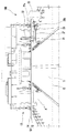
図1は、本発明の一実施形態にかかるコークスオーブンの燃焼室温度自動測定装置を概略的に示す斜視図である。 FIG. 1 is a perspective view schematically showing an automatic combustion chamber temperature measuring device for a coke oven according to an embodiment of the present invention.
図1に示されているように、本発明の一実施形態にかかるコークスオーブンの燃焼室温度自動測定装置100は、コークスオーブン11の装入車13の走行方向を横切るように取付けられる第1レール部10と、第1レール部10に沿って移動可能に取付けられ、第1モータ23の駆動により第1レール部10の長さ方向に沿って走行する第1スライダ20と、第1レール部10と交差する方向に第1スライダ10に取付けられる第2レール部34と、第2レール部34に沿ってコークスオーブン11の燃焼室18方向に昇降可能に取付けられ、第2モータ28の駆動により走行する第2スライダ30と、第2スライダ30の移動に伴って移動するように取付けられ、燃焼室蓋15の位置をセンシングする位置センサ40と、第2スライダ30に取付けられ、位置センサ40のセンシング信号が伝達されると、燃焼室18を開閉する蓋15を選択的にクランピングするクランピング部50と、クランピング部50による蓋15のクランピング状態で、第2スライダ30の移動による蓋15の開放作動が行われると、燃焼室内の温度を測定する温度測定器60とを含む。
As shown in FIG. 1, a coke oven combustion chamber temperature
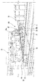
図2は、図1のコークスオーブンの燃焼室温度自動測定装置を他の方向から眺めた斜視図であり、図3は、図1のコークスオーブンの燃焼室温度自動測定装置の第1スライダと第2スライダの構成を示す要部図である。 2 is a perspective view of the coke oven automatic combustion chamber temperature measuring device of FIG. 1 as viewed from another direction. FIG. 3 is a first slider and a first slider of the coke oven automatic combustion chamber temperature measuring device of FIG. It is a principal part figure which shows the structure of 2 slider.
図2および図3に示されているように、第1レール部10は、装入車13の走行方向Aを横切るように取付けられる。第1レール部10は、燃焼室の上部から蓋15と一定間隔離隔した状態で装入車13に取付けられる。このような第1レール部10は、後述する第1スライダ20の移動のために、装入車13の一側および他側方向の間に延長される。
As shown in FIGS. 2 and 3, the
第1レール部10は、装入車の走行方向を横切るように取付けられる第1ビーム12と、第1ビーム12の長さ方向に沿って取付けられる第1走行レール14とを含む。
The
第1ビーム12は、第1レール部10を支持する四角ビームの形態で取付可能である。第1ビーム12の側面には、燃焼室上部の上昇管(uptakes)19または燃焼室から発生する高温に耐えるようにヒートシンク部16が形成されることができる。上昇管19とは、高温のガスが移動する部分をいう。ヒートシンク部16は、第1ビーム12の側面でその内側に引き込まれた複数の凹部および突出部の組み合わせによって形成されることができる。ヒートシンク部16は、第1ビーム12の側面に上昇管19を眺める方向または燃焼室方向の側面に形成される。しかし、ヒートシンク部16は、第1ビーム12の側面の1つの位置に限定することなく、第1ビーム12の全周領域または選択された側面の一部に形成されることも可能である。
The
第1走行レール14は、第1ビーム12の長さに対応する長さで第1ビーム12の上側に取付けられる。第1走行レール14は、第1ビーム12の上側から突出した状態で取付けられ、第1スライダ20のスライディング作動が行われる。第1スライダ20は、ローラ29を含む。このローラ29は、第1走行レール14との接触部分が凹形状を有する凹ローラに取付可能である。したがって、第1走行レール14は、突出した形状が、ローラ29と容易に結合するように凸状に突出する。ここで、ローラ29を、凹ローラを適用するのではなく、四角ローラを適用すると、第1走行レール14の突出した形状も併せて四角形状に変更されることはもちろんである。第1走行レール14は、第1ビーム12の上側および下側にそれぞれ形成されることができる。これは、第1走行レール14上で第1スライダ20の安定したスライディング作動が行われるようにするためである。このようなローラ29のローリング駆動は、第1スライダ20を説明しながら、より詳細に説明する。第1ビーム12の長さ方向には、ラックギヤ16が取付けられる。
The first traveling
ラックギヤ16は、第1スライダ20のスライディング駆動力を伝達するために取付けられる。
The
図4は、第1ビームに第1スライダの取付を示す要部断面図である。 FIG. 4 is a cross-sectional view of the main part showing attachment of the first slider to the first beam.
図4に示されているように、第1スライダ20は、第1ビーム12にスライディング可能に取付けられるブラケット21と、ブラケット21に取付けられる第1モータ23と、第1モータ23の駆動軸に取付けられ、ラックギヤ16に噛み合って駆動力を伝達するピニオンギヤ27とを含む。
As shown in FIG. 4, the
ブラケット21は、第1ビーム12の上側でスライディングされ、内部に取付空間を形成して、第1モータ23と、ローラ29と、ピニオンギヤ27とが取付けられる。ブラケット21は、第1モータ23と、ローラ29と、ピニオンギヤ27との取付および保護のために、第1ビーム12の上側を覆うように曲げられて延長可能である。
The
第1モータ23は、ブラケット21に本体部分が取付けられ、駆動軸25は、第1ビーム12方向に向かうように取付けられる。第1モータ23の駆動軸25には、ピニオンギヤ27が取付けられる。ピニオンギヤ27は、第1ビーム12のラックギヤ16に噛み合って第1モータ23の駆動力を伝達する。これにより、第1スライダ20は、ラックギヤ16とピニオンギヤ27との噛み合い駆動によりスライディング駆動が行われる。ローラ29は、ブラケット21にローリング可能に取付けられ、第1走行レール14上でローリング駆動される。ローラ29は、第1スライダ20のスライディング作動時に、ガイド作用によって安定したスライディング作動が行われるようにする。このため、ローラ29は、第1ビーム12を介して第1ビーム12の上側および下側にそれぞれ複数個取付可能である。ローラ29の取付数は、本発明の実施形態では、上側および下側にそれぞれ3つを取付けることができるが、安定したガイド作用および構成上レイアウトの適切な選択のために、ローラの個数は、限定されることなく、変更可能である。
As for the
このような第1スライダ20のスライディング作動は、作業者が装入車の作動を実施するに伴って移動し、燃焼室上部の蓋15の位置に移動する。つまり、装入車の装入駆動が行われると、作動信号が第1モータ23に伝達されて、第1スライダ20のスライディング駆動が行われる。そして、第1スライダ20の停止は、後述する位置センサ40の作動によって燃焼室蓋15の位置がセンシングされると停止する。次に、第2スライダ30は、第1スライダ20の停止位置で下降作動が行われ、燃焼室蓋15のクランピング作動が行われるようにする。第2スライダ30は、第2ビーム22に沿ってスライディング作動が行われる。
Such sliding operation of the
第2レール部34は、第1レール部10と交差する方向に第1スライダ20のブラケット21に取付けられる。つまり、第2レール部は、第1スライダ20の水平移動に伴って移動する。
The
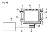
図5は、第2レール部および第2モータを概略的に示す側面図であり、図6は、図5のV−V線に沿って切断した図である。 FIG. 5 is a side view schematically showing the second rail portion and the second motor, and FIG. 6 is a view cut along the line V-V in FIG. 5.
図5および図6に示されているように、第2レール部34は、第1ビーム12と交差する方向に移動可能に取付けられる第2ビーム22と、第2ビーム22の長さ方向に沿って取付けられる第2走行レール31とを含む。参照番号「21a」は、第2レール部34を取付けるための取付ブラケットを表す。
As shown in FIGS. 5 and 6, the
第2ビーム22は、第1ビーム12と交差する方向にブラケット21に取付けられる。第2ビーム22と第1ビーム12との交差角度は垂直に交差して第2ビーム22の駆動が行われる。第2ビーム22の取付角度は、スライディング作動に連動して蓋15のクランピング作動が円滑に行われるようにするためである。つまり、第2ビーム22が蓋方向に垂直に昇降するようにし、より少ない力で蓋15のクランピング作動が行われることが可能である。このような蓋15のクランピング作動は、後述するクランピング部50を説明しながら、より詳細に説明する。
The
第2ビーム22の側面には、上昇管19の高熱から第2ビーム22の変形を防止するようにヒートシンク部24が形成される。ヒートシンク部24は、第2ビーム22の側面でその内側に引き込まれた凹部および突出部の組み合わせによって形成される。第2ビーム22に形成されるヒートシンク部24は、上昇管側にのみ形成されるか、第2ビーム22の一側面に限定することなく、全周にわたって形成されることも可能である。
A
第2ビーム22の長さ方向には、ラックギヤ26が取付けられる。ラックギヤ26は、ブラケット21に取付けられる第2モータ28の駆動軸に取付けられるピニオンギヤ23に噛み合う。したがって、第2ビーム22は、第2モータ28の駆動により蓋15方向にスライディング作動が行われる。このような第2モータ28の駆動は、位置センサ40が作動して蓋15のセンシング作動が行われると、第2ビーム22を下降するように駆動される。第2ビーム22には、第2走行レール31が取付けられる。
A
第2走行レール31は、第2ビーム22の側面から突出して取付けられる。第2走行レール31は、第2ビーム22の両側で、第2ビーム22の長さ方向に沿って一対で取付可能である。第2ビーム22は、ブラケット21に取付けられるローラ32のローリング駆動によりガイドされて昇降作動が行われる。ローラ32は、ローリングされる接触面が凹形状を有する凹ローラに取付可能である。もちろん、ローラ32が凹ローラに適用されると、第2走行レール31は凹状に突出する。第2ビーム22の先端には、第2スライダ30が取付けられる。
The second traveling
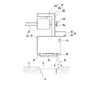
図7は、第2スライダおよびクランピングセンサの取付を概略的に示す図である。 FIG. 7 is a diagram schematically showing attachment of the second slider and the clamping sensor.
図7に示されているように、第2スライダ30は、第2ビーム22の端部に取付けられる連結バー37と、連結バー37に取付けられる昇降体33とを含む。
As shown in FIG. 7, the
連結バー37は、一端が第2ビーム22の端部に連結され、他端は第1ビーム12に水平な方向に延長される。連結バー37は、第2ビーム22のスライディング移動に伴って蓋15方向に昇降する。連結バー37は、棒状または角を有するバー状に取付けられる。昇降体33は、連結バー37の延長された他端に取付けられる。昇降体33には、蓋15のクランピング作動をセンシングするクランピングセンサ35が取付けられる。
One end of the
クランピングセンサ35は、昇降体33に取付けられる昇降ブラケット35aと、連結バー37の端部に取付けられ、昇降ブラケット35aにスライディング可能に取付けられる昇降ボディー35bと、昇降ボディー35bと昇降ブラケット35aとの間に取付けられるロードセル35cとを含む。
The clamping
昇降ブラケット35aは、昇降体33に昇降可能に取付けられる。昇降ブラケット35aの昇降作動可能な取付のために、昇降ブラケット35aの側面には、長孔形状の結合孔35dが形成される。結合孔35dには、昇降ボディー35bから突出する結合突部35eが挿入される。結合突部35eの端部には引っ掛かり部が形成されて、昇降ブラケット35aとの結合解除を防止する。これにより、昇降ブラケット35aの昇降作動は、結合孔35dの長さに対応して昇降作動が行われる。
The raising / lowering
昇降ブラケット35aと昇降ボディー35bとの間にはロードセル35cが取付けられる。ロードセル35cは、昇降ボディー35bの上側に取付けられ、昇降ブラケット35aと昇降ボディー35bの相対運動に応じた接触および接触解除をセンシングし、蓋15とクランピング部50とが接触したか否かをセンシングする。
A
以下、ロードセル35cを用いたクランピングセンサの蓋のセンシング作動をより詳細に説明する。
Hereinafter, the sensing operation of the lid of the clamping sensor using the
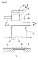
まず、図9に示されているように、位置センサ40を介して蓋15のセンシングが行われると、第2モータ28の駆動により第2ビーム22が下降する。
First, as shown in FIG. 9, when the
次に、図9bに示されているように、第2スライダ30が第2ビーム22の下降に伴って下降し、図9cに示されているように、クランピング部50が蓋15に接触して下降作動が停止する。
Next, as shown in FIG. 9b, the
次に、図9cに示されているように、クランピング部50に連結された昇降ブラケット35aも併せて下降作動が停止し、昇降ボディー35bは、下降方向に慣性力で一定距離下降作動が継続的に行われる。このような昇降ボディー35bの下降は、長孔35dの長さに限定して下降する。
Next, as shown in FIG. 9c, the lowering operation of the elevating
次に、昇降ボディー35bの上側のロードセル35cと昇降ブラケット35aとの接触が解除される。これにより、ロードセル35cは、圧力の変化が発生し、クランピング部50と蓋15との接触を容易にセンシングすることができる。
Next, the contact between the
前述したように、クランピング部50の下降は、位置センサ40を用いて蓋15の位置をセンシングすると、クランピング部50の下降作動が行われる。
As described above, when the clamping
位置センサ40は、第2スライダ30の昇降体33に取付けられる。位置センサ40は、マグネチックセンサで構成されることができる。つまり、マグネチックセンサは、磁力線により動作するものであって、蓋15がマグネチックセンサの下部に位置すると、磁力線の変動をセンシングして蓋15のセンシング作動が行われる。このような位置センサ40のセンシングにより蓋15の正確な位置がセンシングされると、第2スライダ30の昇降体33が下降して、クランピング部50が蓋15をクランピングする。
The
図8は、昇降体の底面から眺めたクランピング部を示す図である。 FIG. 8 is a diagram illustrating the clamping unit viewed from the bottom surface of the lifting body.
図8に示されているように、クランピング部50は、昇降体33の底面に電磁石によって取付けられる。このようなクランピング部50の電磁石は、昇降体33の底面に1つまたは2つ以上の複数個が取付可能である。クランピング部50の作動は、クランピングセンサ35のセンシングにより蓋15と接触したと判断されると、電源が印加されることによる電磁石の磁化作用により蓋15をクランピングする。
As shown in FIG. 8, the clamping
クランピング部50は、蓋のクランピング作動が完了すると、一側に移動作動が行われる。つまり、第1モータ23の駆動により第1スライダ20の移動作動が行われ、蓋15の移動作動が行われて燃焼室18の開放が行われる。次に、昇降体33に取付けられた温度測定器60を介して燃焼室内の温度測定が行われる。
When the clamping operation of the lid is completed, the clamping
温度測定器60は、昇降体33の側面に突出する突出ブラケット61と、突出ブラケット61に取付けられ、燃焼室内の温度を遠隔で測定するパイロメータ63とを含む。
The
突出ブラケット61は、昇降体33の側面または昇降ブラケット35aに一端が取付けられ、他端は昇降体33の外側に延長して取付可能である。突出ブラケット61は、プレート状に突出してパイロメータ63が昇降体33の外側に離隔して取付けられるようにする。
One end of the protruding
パイロメータ63の作用は、高温の物体が高温になると、熱放射が強くなって赤色から白熱色に変化していくことを利用して、色や強度を測定、温度をセンシングする温度計をいう。このようなパイロメータ63は、高温の測定対象物に直接接触せずに遠隔で温度を測定することが容易である。したがって、コークスオーブンの燃焼室内の温度測定を、燃焼室18を開放した状態で遠隔で測定可能なため、正確な温度の測定および安全事故の発生を防止することができる。昇降体33には、パイロメータ63を燃焼室の高温から保護する冷却器70が取付けられる。
The action of the
冷却器70は、昇降体33に取付けられ、冷却エア71を噴射するエア噴射ノズル70(冷却器と参照番号が同一)が取付けられる。エア噴射ノズル70は、パイロメータ63の底面に冷却エア71を噴射してエアカーテンの作用が行われるようにする。したがって、燃焼室の高温がパイロメータ63に直接伝達されないようにすることにより、損傷が発生しない。
The cooler 70 is attached to the elevating
一方、クランピング部50には、蓋15の外側の異物を除去する異物除去器80が取付けられる。
On the other hand, a
異物除去器80は、昇降体33の底面に取付けられ、蓋15方向にエアを噴射するエアブロワー80(異物除去器と参照番号が同一)を含む。これにより、クランピング部50を用いた蓋15のクランピング作動前に蓋15にエア81を噴射して、蓋15の表面の異物を除去することにより、クランピング作動が円滑に行われるようにする。
The
以下、上記の構成を有する本発明の一実施形態にかかるコークスオーブンの燃焼室温度自動測定装置の作用を説明する。 Hereinafter, an operation of the automatic combustion chamber temperature measuring device for a coke oven according to an embodiment of the present invention having the above-described configuration will be described.
まず、作業者は、測定しようとするコークスオーブンの燃焼室の測定ポイントを入力する。 First, an operator inputs a measurement point of a combustion chamber of a coke oven to be measured.
次に、第1スライダ20は、第1レール部10に沿って移動する。このような第1スライダ20の移動は、第1モータ23の駆動力により行われる。
Next, the
次に、図9に示されているように、第1スライダ20の移動に伴って移動する位置センサ40を介して、予め設定された燃焼室の測定ポイント、つまり、測定しようとする燃焼室蓋の位置をセンシングする。
Next, as shown in FIG. 9, the measurement point of the combustion chamber set in advance via the
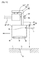
次に、位置センサ40を介して測定ポイントの蓋の位置がセンシングされると、図10に示されているように、測定位置の蓋にエアブロワー80を用いてエアを噴射する。これにより、蓋15の上側の異物を除去する。
Next, when the position of the lid of the measurement point is sensed via the
そして、図11に示されているように、第2スライダ30の下降によりクランピング部50と蓋15との接触が行われる。ここで、蓋15とクランピング部50との接触は、クランピングセンサ35を介してセンシングされる。
Then, as shown in FIG. 11, when the
次に、図12に示されているように、クランピングセンサ35の蓋15の接触センシング信号が伝達されると、クランピング部の電磁石が磁化して蓋15のクランピング作用が行われる。
Next, as shown in FIG. 12, when the contact sensing signal of the
次に、第2スライダ30が蓋15の上側に移動し、燃焼室から蓋15を除去して燃焼室が開放されるようにする。
Next, the
次に、図13に示されているように、第2スライダ30は、第1レール部10に沿って一定距離移動し、パイロメータ63が燃焼室の位置に移動するようにする。ここで、パイロメータ63の移動作動時にエア噴射ノズル70のエアが噴射され、燃焼室12の高温からパイロメータ63の損傷を防止する。
Next, as shown in FIG. 13, the
次に、パイロメータ63は、燃焼室内の温度を遠隔で正確に自動的に測定する。したがって、作業者の手業務による燃焼室の温度測定を代替して、正確で安全事故が発生することなく、燃焼室の温度の測定が可能である。
Next, the
以上、本発明を図面に示された実施形態を参照して説明した。しかし、本発明は、これに限定されず、本発明の属する技術分野における通常の知識を有する者によって本発明と均等な範囲に属する多様な変形例または他の実施形態が可能である。したがって、本発明の真の保護範囲は、下記の特許請求の範囲によって定められなければならない。 The present invention has been described above with reference to the embodiments shown in the drawings. However, the present invention is not limited to this, and various modifications or other embodiments belonging to a scope equivalent to the present invention can be made by those having ordinary knowledge in the technical field to which the present invention belongs. Accordingly, the true scope of protection of the present invention must be determined by the following claims.
図1に示されているように、本発明の一実施形態にかかるコークスオーブンの燃焼室温度自動測定装置100は、コークスオーブン11の装入車13の走行方向を横切るように取付けられる第1レール部10と、第1レール部10に沿って移動可能に取付けられ、第1モータ23の駆動により第1レール部10の長さ方向に沿って走行する第1スライダ20と、第1レール部10と交差する方向に第1スライダ20に取付けられる第2レール部34と、第2レール部34に沿ってコークスオーブン11の燃焼室18方向に昇降可能に取付けられ、第2モータ28の駆動により走行する第2スライダ30と、第2スライダ30の移動に伴って移動するように取付けられ、燃焼室蓋15の位置をセンシングする位置センサ40と、第2スライダ30に取付けられ、位置センサ40のセンシング信号が伝達されると、燃焼室18を開閉する蓋15を選択的にクランピングするクランピング部50と、クランピング部50による蓋15のクランピング状態で、第2スライダ30の移動による蓋15の開放作動が行われると、燃焼室内の温度を測定する温度測定器60とを含む。
As shown in FIG. 1, a coke oven combustion chamber temperature
第1ビーム12は、第1レール部10を支持する四角ビームの形態で取付可能である。第1ビーム12の側面には、燃焼室上部の上昇管(uptakes)19または燃焼室から発生する高温に耐えるようにヒートシンク部(図示せず)が形成されることができる。上昇管19とは、高温のガスが移動する部分をいう。ヒートシンク部は、第1ビーム12の側面でその内側に引き込まれた複数の凹部および突出部の組み合わせによって形成されることができる。ヒートシンク部は、第1ビーム12の側面に上昇管19を眺める方向または燃焼室方向の側面に形成される。しかし、ヒートシンク部は、第1ビーム12の側面の1つの位置に限定することなく、第1ビーム12の全周領域または選択された側面の一部に形成されることも可能である。
The
図5は、第2レール部および第2モータを概略的に示す側面図であり、図6は、図5のVI−VI線に沿って切断した図である。
FIG. 5 is a side view schematically showing the second rail portion and the second motor, and FIG. 6 is a view cut along line VI - VI in FIG.
第2ビーム22の長さ方向には、ラックギヤ26が取付けられる。ラックギヤ26は、ブラケット21に取付けられる第2モータ28の駆動軸に取付けられるピニオンギヤ23’に噛み合う。したがって、第2ビーム22は、第2モータ28の駆動により蓋15方向にスライディング作動が行われる。このような第2モータ28の駆動は、位置センサ40が作動して蓋15のセンシング作動が行われると、第2ビーム22を下降するように駆動される。第2ビーム22には、第2走行レール31が取付けられる。
A
次に、図10に示されているように、第2スライダ30が第2ビーム22の下降に伴って下降し、図11に示されているように、クランピング部50が蓋15に接触して下降作動が停止する。
Next, as shown in FIG. 10 , the
次に、図11に示されているように、クランピング部50に連結された昇降ブラケット35aも併せて下降作動が停止し、昇降ボディー35bは、下降方向に慣性力で一定距離下降作動が継続的に行われる。このような昇降ボディー35bの下降は、長孔35dの長さに限定して下降する。
Next, as shown in FIG. 11 , the raising / lowering
Claims (20)
前記第1レール部に沿って移動可能に取付けられ、第1モータの駆動により前記第1レール部の長さ方向に沿って走行する第1スライダと、
前記第1レール部と交差する方向に前記第1スライダに取付けられる第2レール部と、
前記第2レール部に沿って前記コークスオーブンの燃焼室方向に昇降可能に取付けられ、第2モータの駆動により走行する第2スライダと、
前記第2スライダの移動に伴って移動するように取付けられ、燃焼室蓋の位置をセンシングする位置センサと、
前記第2スライダに取付けられ、前記位置センサのセンシング信号が伝達されると、前記燃焼室を開閉する蓋を選択的にクランピングするクランピング部と、
前記クランピング部による蓋のクランピング状態で、前記第2スライダの移動による蓋の開放作動が行われると、前記燃焼室内の温度を測定する温度測定器とを含むことを特徴とするコークスオーブンの燃焼室温度自動測定装置。 A first rail portion attached so as to cross the traveling direction of the coke oven charging vehicle;
A first slider that is movably attached along the first rail portion and travels along the length direction of the first rail portion by driving a first motor;
A second rail portion attached to the first slider in a direction crossing the first rail portion;
A second slider which is attached to the coke oven in the direction of the combustion chamber along the second rail portion so as to be movable up and down, and travels by driving a second motor;
A position sensor which is attached to move with the movement of the second slider and senses the position of the combustion chamber lid;
A clamping unit that is attached to the second slider and selectively clamps a lid that opens and closes the combustion chamber when a sensing signal of the position sensor is transmitted;
A coke oven comprising: a temperature measuring device that measures a temperature in the combustion chamber when the lid is opened by the movement of the second slider in a clamping state of the lid by the clamping unit. Combustion chamber temperature automatic measuring device.
前記装入車の走行方向を横切るように取付けられる第1ビームと、
前記第1ビームの長さ方向に沿って取付けられる第1走行レールとを含むことを特徴とする請求項1に記載のコークスオーブンの燃焼室温度自動測定装置。 The first rail portion is
A first beam mounted across the direction of travel of the charging vehicle;
The apparatus for automatically measuring a combustion chamber temperature of a coke oven according to claim 1, further comprising: a first traveling rail attached along a length direction of the first beam.
前記第1ビームにスライディング可能に取付けられるブラケットと、
前記ブラケットに取付けられる第1モータと、
前記第1モータの駆動軸に取付けられ、前記ラックギヤに噛み合って駆動力を伝達するピニオンギヤとを含むことを特徴とする請求項4に記載のコークスオーブンの燃焼室温度自動測定装置。 The first slider is
A bracket slidably attached to the first beam;
A first motor attached to the bracket;
5. The coke oven combustion chamber temperature automatic measuring device according to claim 4, further comprising: a pinion gear which is attached to a drive shaft of the first motor and meshes with the rack gear to transmit a driving force.
前記第1ビームと交差する方向に移動可能に取付けられる第2ビームと、
前記第2ビームの長さ方向に沿って取付けられる第2走行レールとを含むことを特徴とする請求項6に記載のコークスオーブンの燃焼室温度自動測定装置。 The second rail portion is
A second beam movably mounted in a direction intersecting the first beam;
The combustion chamber temperature automatic measuring device of a coke oven according to claim 6, further comprising a second traveling rail attached along a length direction of the second beam.
前記第2モータの駆動軸には、前記ラックギヤに噛み合って駆動力を伝達して、前記第2ビームが前記第1ビームと交差する方向に移動するようにするピニオンギヤとを含むことを特徴とする請求項8に記載のコークスオーブンの燃焼室温度自動測定装置。 The second motor is attached to the bracket,
The drive shaft of the second motor includes a pinion gear that meshes with the rack gear and transmits a driving force so that the second beam moves in a direction intersecting the first beam. The apparatus for automatically measuring a combustion chamber temperature of a coke oven according to claim 8.
前記第2ビームの端部に取付けられる連結バーと、
前記連結バーに取付けられる昇降体とを含むことを特徴とする請求項9に記載のコークスオーブンの燃焼室温度自動測定装置。 The second slider is
A connecting bar attached to an end of the second beam;
The apparatus for automatically measuring a combustion chamber temperature of a coke oven according to claim 9, further comprising an elevating body attached to the connection bar.
前記蓋のクランピングを感知するクランピングセンサを含むことを特徴とする請求項10に記載のコークスオーブンの燃焼室温度自動測定装置。 The second slider is
The apparatus for automatically measuring a combustion chamber temperature of a coke oven according to claim 10, further comprising a clamping sensor that senses clamping of the lid.
前記昇降体に取付けられる昇降ブラケットと、
前記連結バーの端部に取付けられ、前記昇降ブラケットにスライディング可能に取付けられる昇降ボディーと、
前記昇降ボディーと前記昇降ブラケットとの間に取付けられるロードセルとを含み、
前記クランピング部が前記蓋をクランピングすると、前記ロードセルの電圧変化が発生し、蓋がクランピングされているか否かをセンシングすることを特徴とする請求項11に記載のコークスオーブンの燃焼室温度自動測定装置。 The clamping sensor is
A lifting bracket attached to the lifting body;
An elevating body attached to an end of the connecting bar and slidably attached to the elevating bracket;
A load cell attached between the elevating body and the elevating bracket;
The combustion chamber temperature of the coke oven according to claim 11, wherein when the clamping unit clamps the lid, a voltage change of the load cell is generated and sensing whether the lid is clamped or not. Automatic measuring device.
前記昇降ボディーは、
前記結合孔に結合するように突出する結合突部が形成されて、前記昇降ボディーにスライディング可能に取付けられることを特徴とする請求項12に記載のコークスオーブンの燃焼室温度自動測定装置。 The elevating bracket is formed with a long hole-shaped coupling hole,
The lifting body is
13. The apparatus for automatically measuring a combustion chamber temperature of a coke oven according to claim 12, wherein a coupling protrusion projecting so as to be coupled to the coupling hole is formed and is slidably attached to the elevating body.
前記昇降体に取付けられるマグネチックセンサを含むことを特徴とする請求項13に記載のコークスオーブンの燃焼室温度自動測定装置。 The position sensor is
The apparatus for automatically measuring a combustion chamber temperature of a coke oven according to claim 13, further comprising a magnetic sensor attached to the elevating body.
前記昇降体の底面に取付けられる電磁石を含むことを特徴とする請求項14に記載のコークスオーブンの燃焼室温度自動測定装置。 The clamping unit is
The apparatus for automatically measuring a combustion chamber temperature of a coke oven according to claim 14, further comprising an electromagnet attached to a bottom surface of the elevating body.
前記昇降体の側面に突出する突出ブラケットと、
前記突出ブラケットに取付けられ、前記燃焼室内の温度を遠隔で測定するパイロメータ(pyrometer)とを含むことを特徴とする請求項15に記載のコークスオーブンの燃焼室温度自動測定装置。 The temperature measuring instrument is
A projecting bracket projecting on a side surface of the lifting body;
The apparatus for automatically measuring a combustion chamber temperature in a coke oven according to claim 15, further comprising a pyrometer attached to the protruding bracket and remotely measuring a temperature in the combustion chamber.
前記昇降体に取付けられ、冷却エアを噴射するエア噴射ノズルを含み、
前記エア噴射ノズルは、
前記昇降体の側面からエアを噴射して、前記燃焼室の高温から前記パイロメータを保護することを特徴とする請求項17に記載のコークスオーブンの燃焼室温度自動測定装置。 The cooler is
An air injection nozzle attached to the elevating body and for injecting cooling air;
The air injection nozzle is
The apparatus for automatically measuring a combustion chamber temperature of a coke oven according to claim 17, wherein air is injected from a side surface of the elevating body to protect the pyrometer from a high temperature of the combustion chamber.
前記昇降体の底面に取付けられ、前記蓋にエアを噴射するエアブロワーを含むことを特徴とする請求項19に記載のコークスオーブンの燃焼室温度自動測定装置。 The foreign matter remover is
The apparatus for automatically measuring a combustion chamber temperature of a coke oven according to claim 19, further comprising an air blower attached to a bottom surface of the elevating body and injecting air onto the lid.
Applications Claiming Priority (3)
| Application Number | Priority Date | Filing Date | Title |
|---|---|---|---|
| KR10-2008-0107433 | 2008-10-31 | ||
| KR1020080107433A KR101009037B1 (en) | 2008-10-31 | 2008-10-31 | Apparstus for measuring the temperature of combustion chamber of cokes oven |
| PCT/KR2009/005768 WO2010050681A2 (en) | 2008-10-31 | 2009-10-09 | Apparatus for automatically measuring the temperature of a combustion chamber of a coke oven |
Publications (2)
| Publication Number | Publication Date |
|---|---|
| JP2012507708A true JP2012507708A (en) | 2012-03-29 |
| JP5608663B2 JP5608663B2 (en) | 2014-10-15 |
Family
ID=42129413
Family Applications (1)
| Application Number | Title | Priority Date | Filing Date |
|---|---|---|---|
| JP2011534376A Expired - Fee Related JP5608663B2 (en) | 2008-10-31 | 2009-10-09 | Coke oven combustion chamber temperature automatic measuring device |
Country Status (4)
| Country | Link |
|---|---|
| JP (1) | JP5608663B2 (en) |
| KR (1) | KR101009037B1 (en) |
| CN (1) | CN102203573B (en) |
| WO (1) | WO2010050681A2 (en) |
Cited By (2)
| Publication number | Priority date | Publication date | Assignee | Title |
|---|---|---|---|---|
| CN105112077A (en) * | 2015-08-14 | 2015-12-02 | 武汉平煤武钢联合焦化有限责任公司 | Coke oven crude gas riser working state monitoring system |
| JP2017506351A (en) * | 2014-02-21 | 2017-03-02 | フサン カンパニー, リミテッドFusang Co., Ltd. | Coke oven combustion chamber temperature measurement device |
Families Citing this family (10)
| Publication number | Priority date | Publication date | Assignee | Title |
|---|---|---|---|---|
| KR101433477B1 (en) * | 2012-12-14 | 2014-08-22 | 주식회사 포스코 | Coke oven combustion chamber opener having a temperature sensing function |
| CN103471732B (en) * | 2013-08-29 | 2015-08-05 | 苏州工业园区华福科技有限公司 | Automatic TME |
| CN107860240A (en) * | 2017-09-22 | 2018-03-30 | 太原理工大学 | Coking furnace roof flue modularization carries lid temperature measuring equipment |
| CN112102976B (en) * | 2019-06-18 | 2024-02-02 | 国家电投集团科学技术研究院有限公司 | Underwater movable measuring device for measuring high-temperature steam spraying condensation temperature |
| CN110617884B (en) * | 2019-08-13 | 2024-05-07 | 山东旷为信息科技有限公司 | Intelligent coke oven straight-running temperature measurement robot system and temperature measurement control method |
| CN111004636A (en) * | 2019-12-19 | 2020-04-14 | 武汉钢铁有限公司 | Automatic temperature measurement robot for straight movement of coke oven |
| CN113618755B (en) * | 2021-10-12 | 2021-12-28 | 陕西祥瑞电气工程自动化有限公司 | Intelligent temperature measuring robot and temperature measuring method for temperature measuring hole in top of coke oven |
| CN113959950B (en) * | 2021-10-28 | 2024-04-12 | 绍兴泊盛科技有限公司 | Detection device for detecting liquid refractive index based on optofluidic chip |
| CN114136480B (en) * | 2021-11-26 | 2024-04-30 | 广东电网有限责任公司 | Temperature detection device |
| CN115265791B (en) * | 2022-06-23 | 2023-05-12 | 安徽工业大学 | Device and method for distinguishing single-number and double-number fire holes of coke oven and automatically and accurately measuring temperature |
Citations (5)
| Publication number | Priority date | Publication date | Assignee | Title |
|---|---|---|---|---|
| JPS57139630A (en) * | 1981-02-23 | 1982-08-28 | Mitsubishi Chem Ind Ltd | Coke oven temperature measuring device |
| JPS5882134A (en) * | 1981-11-11 | 1983-05-17 | Mitsubishi Chem Ind Ltd | Temperature measuring apparatus for coke oven |
| JPS61138689A (en) * | 1984-12-10 | 1986-06-26 | Mitsubishi Chem Ind Ltd | Device for measuring furnace temperature of coke oven |
| JPS61103449U (en) * | 1984-12-10 | 1986-07-01 | ||
| KR20000014717U (en) * | 1998-12-30 | 2000-07-25 | 이구택 | Coke oven combustion chamber temperature measuring device |
Family Cites Families (7)
| Publication number | Priority date | Publication date | Assignee | Title |
|---|---|---|---|---|
| US4447805A (en) * | 1981-02-23 | 1984-05-08 | Mitsubishi Kasei Kogyo Kabushiki Kaisha | Apparatus for measuring temperature of coke ovens |
| JPS6035084A (en) * | 1983-08-08 | 1985-02-22 | Mitsubishi Chem Ind Ltd | Apparatus for measuring temperature of coke oven |
| KR20000014717A (en) * | 1998-08-24 | 2000-03-15 | 윤종용 | System for billing road cost by digital portable telephone |
| KR100524605B1 (en) * | 2001-11-28 | 2005-11-02 | 주식회사 포스코 | Apparatus for measuring the temperature of combustion chamber of cokes oven |
| KR100812161B1 (en) * | 2002-05-29 | 2008-03-12 | 주식회사 포스코 | Apparatus for measuring cokes dry temperature |
| CN1247738C (en) * | 2004-04-08 | 2006-03-29 | 张建 | Automatic method of measuring temperature for coke furnace and system of measuring temperature |
| CN101078653B (en) * | 2007-07-06 | 2010-05-26 | 太原理工大学 | Coke oven combustion chamber temperature metering system and metering method |
-
2008
- 2008-10-31 KR KR1020080107433A patent/KR101009037B1/en not_active IP Right Cessation
-
2009
- 2009-10-09 WO PCT/KR2009/005768 patent/WO2010050681A2/en active Application Filing
- 2009-10-09 JP JP2011534376A patent/JP5608663B2/en not_active Expired - Fee Related
- 2009-10-09 CN CN2009801433873A patent/CN102203573B/en active Active
Patent Citations (5)
| Publication number | Priority date | Publication date | Assignee | Title |
|---|---|---|---|---|
| JPS57139630A (en) * | 1981-02-23 | 1982-08-28 | Mitsubishi Chem Ind Ltd | Coke oven temperature measuring device |
| JPS5882134A (en) * | 1981-11-11 | 1983-05-17 | Mitsubishi Chem Ind Ltd | Temperature measuring apparatus for coke oven |
| JPS61138689A (en) * | 1984-12-10 | 1986-06-26 | Mitsubishi Chem Ind Ltd | Device for measuring furnace temperature of coke oven |
| JPS61103449U (en) * | 1984-12-10 | 1986-07-01 | ||
| KR20000014717U (en) * | 1998-12-30 | 2000-07-25 | 이구택 | Coke oven combustion chamber temperature measuring device |
Cited By (3)
| Publication number | Priority date | Publication date | Assignee | Title |
|---|---|---|---|---|
| JP2017506351A (en) * | 2014-02-21 | 2017-03-02 | フサン カンパニー, リミテッドFusang Co., Ltd. | Coke oven combustion chamber temperature measurement device |
| CN105112077A (en) * | 2015-08-14 | 2015-12-02 | 武汉平煤武钢联合焦化有限责任公司 | Coke oven crude gas riser working state monitoring system |
| CN105112077B (en) * | 2015-08-14 | 2017-06-20 | 武汉平煤武钢联合焦化有限责任公司 | A kind of raw coke over gas riser working state monitoring system |
Also Published As
| Publication number | Publication date |
|---|---|
| JP5608663B2 (en) | 2014-10-15 |
| WO2010050681A3 (en) | 2010-06-17 |
| CN102203573A (en) | 2011-09-28 |
| KR101009037B1 (en) | 2011-01-17 |
| CN102203573B (en) | 2013-11-27 |
| WO2010050681A2 (en) | 2010-05-06 |
| KR20100048329A (en) | 2010-05-11 |
Similar Documents
| Publication | Publication Date | Title |
|---|---|---|
| JP5608663B2 (en) | Coke oven combustion chamber temperature automatic measuring device | |
| KR101129179B1 (en) | An apparatus for centering drop sleeve of charging car | |
| KR100524605B1 (en) | Apparatus for measuring the temperature of combustion chamber of cokes oven | |
| CN214066421U (en) | Air tightness detection device for automobile warm air radiator | |
| KR101246234B1 (en) | Heating furnace and control method thereof | |
| JP4851127B2 (en) | Insulation box insertion method and insertion device | |
| JP4022008B2 (en) | Coke oven inspection and repair equipment and coke oven repair method | |
| KR200310343Y1 (en) | Coke Oven Combustion Chamber Temperature Measuring Device_ | |
| JP4454175B2 (en) | Heat insulation device for coke oven repair | |
| JP4718027B2 (en) | Observation and repair equipment for coke oven combustion chamber | |
| CN220447223U (en) | Hot melt frame pressing machine of intelligent instrument panel | |
| CN220920862U (en) | Ladle car connects inserts motor robot system | |
| KR102203377B1 (en) | Insulation apparatus for repairing of coke oven | |
| JPH0820778A (en) | Temporary cover for repairing coke oven wall | |
| KR20100050852A (en) | A hood devicef for collecting dust in furnace | |
| CN113843330B (en) | Hot stamping steel plate emissivity calibration experiment platform | |
| CN208087655U (en) | A kind of small set of blast furnace uptake is with applying mechanically mobile infrared temperature measurement system | |
| KR20080099699A (en) | Apparatus for measuring filling level of cokes | |
| KR100938287B1 (en) | Device measuring temperature charging inlet of cokes oven | |
| CN113957223B (en) | Box-type heating furnace for heat treatment | |
| KR101766543B1 (en) | Apparatus and method for measuring temperature of combustionchamber in a coke oven | |
| JP3156901B2 (en) | Method and apparatus for repairing the furnace wall below the coal mouth of the coke oven | |
| KR101736004B1 (en) | Conservation device of blast furnace | |
| JP3565082B2 (en) | Method and apparatus for correcting ram beam curvature of coke extruder in coke oven | |
| SU817060A1 (en) | Device for liquid metal treatment |
Legal Events
| Date | Code | Title | Description |
|---|---|---|---|
| A621 | Written request for application examination |
Free format text: JAPANESE INTERMEDIATE CODE: A621 Effective date: 20120913 |
|
| A977 | Report on retrieval |
Free format text: JAPANESE INTERMEDIATE CODE: A971007 Effective date: 20130315 |
|
| A131 | Notification of reasons for refusal |
Free format text: JAPANESE INTERMEDIATE CODE: A131 Effective date: 20140204 |
|
| A521 | Written amendment |
Free format text: JAPANESE INTERMEDIATE CODE: A523 Effective date: 20140403 |
|
| TRDD | Decision of grant or rejection written | ||
| A01 | Written decision to grant a patent or to grant a registration (utility model) |
Free format text: JAPANESE INTERMEDIATE CODE: A01 Effective date: 20140805 |
|
| A61 | First payment of annual fees (during grant procedure) |
Free format text: JAPANESE INTERMEDIATE CODE: A61 Effective date: 20140901 |
|
| R150 | Certificate of patent or registration of utility model |
Ref document number: 5608663 Country of ref document: JP Free format text: JAPANESE INTERMEDIATE CODE: R150 |
|
| R250 | Receipt of annual fees |
Free format text: JAPANESE INTERMEDIATE CODE: R250 |
|
| R250 | Receipt of annual fees |
Free format text: JAPANESE INTERMEDIATE CODE: R250 |
|
| R250 | Receipt of annual fees |
Free format text: JAPANESE INTERMEDIATE CODE: R250 |
|
| LAPS | Cancellation because of no payment of annual fees |