JP2012506597A - How to achieve recognizable power management - Google Patents
How to achieve recognizable power management Download PDFInfo
- Publication number
- JP2012506597A JP2012506597A JP2011533304A JP2011533304A JP2012506597A JP 2012506597 A JP2012506597 A JP 2012506597A JP 2011533304 A JP2011533304 A JP 2011533304A JP 2011533304 A JP2011533304 A JP 2011533304A JP 2012506597 A JP2012506597 A JP 2012506597A
- Authority
- JP
- Japan
- Prior art keywords
- power
- state
- performance
- processing unit
- server
- Prior art date
- Legal status (The legal status is an assumption and is not a legal conclusion. Google has not performed a legal analysis and makes no representation as to the accuracy of the status listed.)
- Pending
Links
Images
Classifications
-
- G—PHYSICS
- G06—COMPUTING; CALCULATING OR COUNTING
- G06F—ELECTRIC DIGITAL DATA PROCESSING
- G06F1/00—Details not covered by groups G06F3/00 - G06F13/00 and G06F21/00
- G06F1/26—Power supply means, e.g. regulation thereof
- G06F1/32—Means for saving power
- G06F1/3203—Power management, i.e. event-based initiation of a power-saving mode
- G06F1/3206—Monitoring of events, devices or parameters that trigger a change in power modality
- G06F1/3209—Monitoring remote activity, e.g. over telephone lines or network connections
-
- G—PHYSICS
- G06—COMPUTING; CALCULATING OR COUNTING
- G06F—ELECTRIC DIGITAL DATA PROCESSING
- G06F1/00—Details not covered by groups G06F3/00 - G06F13/00 and G06F21/00
- G06F1/26—Power supply means, e.g. regulation thereof
-
- G—PHYSICS
- G06—COMPUTING; CALCULATING OR COUNTING
- G06F—ELECTRIC DIGITAL DATA PROCESSING
- G06F1/00—Details not covered by groups G06F3/00 - G06F13/00 and G06F21/00
- G06F1/26—Power supply means, e.g. regulation thereof
- G06F1/32—Means for saving power
- G06F1/3203—Power management, i.e. event-based initiation of a power-saving mode
- G06F1/3234—Power saving characterised by the action undertaken
- G06F1/324—Power saving characterised by the action undertaken by lowering clock frequency
-
- G—PHYSICS
- G06—COMPUTING; CALCULATING OR COUNTING
- G06F—ELECTRIC DIGITAL DATA PROCESSING
- G06F1/00—Details not covered by groups G06F3/00 - G06F13/00 and G06F21/00
- G06F1/26—Power supply means, e.g. regulation thereof
- G06F1/32—Means for saving power
- G06F1/3203—Power management, i.e. event-based initiation of a power-saving mode
- G06F1/3234—Power saving characterised by the action undertaken
- G06F1/3296—Power saving characterised by the action undertaken by lowering the supply or operating voltage
-
- G—PHYSICS
- G06—COMPUTING; CALCULATING OR COUNTING
- G06F—ELECTRIC DIGITAL DATA PROCESSING
- G06F9/00—Arrangements for program control, e.g. control units
- G06F9/06—Arrangements for program control, e.g. control units using stored programs, i.e. using an internal store of processing equipment to receive or retain programs
- G06F9/46—Multiprogramming arrangements
- G06F9/50—Allocation of resources, e.g. of the central processing unit [CPU]
- G06F9/5094—Allocation of resources, e.g. of the central processing unit [CPU] where the allocation takes into account power or heat criteria
-
- Y—GENERAL TAGGING OF NEW TECHNOLOGICAL DEVELOPMENTS; GENERAL TAGGING OF CROSS-SECTIONAL TECHNOLOGIES SPANNING OVER SEVERAL SECTIONS OF THE IPC; TECHNICAL SUBJECTS COVERED BY FORMER USPC CROSS-REFERENCE ART COLLECTIONS [XRACs] AND DIGESTS
- Y02—TECHNOLOGIES OR APPLICATIONS FOR MITIGATION OR ADAPTATION AGAINST CLIMATE CHANGE
- Y02D—CLIMATE CHANGE MITIGATION TECHNOLOGIES IN INFORMATION AND COMMUNICATION TECHNOLOGIES [ICT], I.E. INFORMATION AND COMMUNICATION TECHNOLOGIES AIMING AT THE REDUCTION OF THEIR OWN ENERGY USE
- Y02D10/00—Energy efficient computing, e.g. low power processors, power management or thermal management
Landscapes
- Engineering & Computer Science (AREA)
- Theoretical Computer Science (AREA)
- Physics & Mathematics (AREA)
- General Engineering & Computer Science (AREA)
- General Physics & Mathematics (AREA)
- Software Systems (AREA)
- Power Sources (AREA)
- Management, Administration, Business Operations System, And Electronic Commerce (AREA)
Abstract
CPUレベル電力管理の技術によって、企業サービス利用の異なる構成と、電力使用を相関させるための統合された環境及び計算パワーモニタリングにより生成されるデータセンタの包括的な動的モデルに基づき電力管理アプローチを統合することによって、データセンタにおける全体的な電力使用の効率性を向上させるシステム及び方法。 CPU-level power management technology provides a power management approach based on a comprehensive dynamic model of the data center generated by different configurations of enterprise service usage, an integrated environment to correlate power usage and computational power monitoring Systems and methods that improve overall power usage efficiency in a data center by integrating.
Description
本発明は、電力管理に関する。特に、データセンタ及びサーバ施設に設けられる計算及び電気機器の最適化された電力管理を実現するシステム及び方法が提供される。 The present invention relates to power management. In particular, systems and methods are provided that implement optimized power management of computation and electrical equipment provided in data centers and server facilities.
今日、大部分の企業組織は、データ解析、サプライチェーン管理、在庫追跡、オンライン取引及びカスタマサポートを含む企業サービスのため計算パワーに依拠している。この計算パワーは、ウェブサービス、ウェブポータル、リース又は所有されるデータセンタで運用される他のオープンソース及び専用アプリケーションの形態をとる。これらのデータセンタは、データセンタコピーペースト機器と間接的には湿度及び温度調整装置とを介す電力のかなりの使用となる。最近のデータは、サーバ企業に提供される電力のほとんど50%が冷却インフラストラクチャに費やされ、50%未満しかサーバ消費を実際には使用しないことを示す。サーバ内の活動の実行中の電力使用量は、熱負荷に変換される。電力量は、ラック内のサーバハードウェアの相対位置、サーバの空気の流れの特性及び本開示で後述される他の多数のパラメータに依存する動作中の温度を維持するよう固守される。データセンタにより利用される計算パワーと供給される電力との間に直接的な関係があったとしても、当該関係に影響を与えるファクタは多数あり、効果的な制御のために要求される精度までそれらを定量化するのに必要とされる装置及び解析は困難である。既存の電力制御機構は、所与の電源ユニットとこのような利用とを関連付けしようとするものでなく、電力利用、データセンタ及びサーバ施設のグローバルな最適化には不足するものである。相互参照される出願は、異なる環境動作状態の下で消費される協調的なサーバコピーデジタル電力測定及び電力ユニットを利用してモニタリング及び制御を実現するためのシステマティックな処理装置を開示している。相互参照される出願は、インフラストラクチャ施設における各種データセンタサーバ企業に対処するのに必要とされる適応的な学習を提供するための方法を開示する。上述されたアプローチで用いられるヒューリスティックは、サーバハードウェアを考慮する。 Today, most enterprise organizations rely on computational power for enterprise services including data analysis, supply chain management, inventory tracking, online trading and customer support. This computational power takes the form of web services, web portals, leases or other open source and dedicated applications that operate in owned data centers. These data centers represent a significant use of power through data center copy paste equipment and indirectly through humidity and temperature regulation devices. Recent data shows that almost 50% of the power provided to server companies is spent on the cooling infrastructure, and less than 50% actually uses server consumption. The power usage during the activity in the server is converted into a heat load. The amount of power is adhered to to maintain the operating temperature depending on the relative position of the server hardware in the rack, the airflow characteristics of the server, and a number of other parameters described later in this disclosure. Even if there is a direct relationship between the computational power used by the data center and the power supplied, there are many factors that affect that relationship, up to the accuracy required for effective control. The equipment and analysis required to quantify them is difficult. Existing power control mechanisms do not attempt to correlate such usage with a given power supply unit, and are insufficient for global optimization of power usage, data centers and server facilities. The cross-referenced application discloses a systematic processing unit for implementing monitoring and control utilizing coordinated server copy digital power measurement and power units consumed under different environmental operating conditions. The cross-referenced application discloses a method for providing the adaptive learning needed to address various data center server companies in infrastructure facilities. The heuristic used in the approach described above considers server hardware.
いくつかの方法が相互参照される出願において開示されるが、本願では、低レベル電力管理で使用され、データセンタによって用いられる計算パワーと供給される電力との間の直接的な関係をモニタリング及び制御するのには適用されなかった技術が開示される。具体的には、マザーボード及びCPUレベルにおけるエネルギー消費量を制御する技術がまた、データセンタのサーバにより使用される電力をモニタリング及び制御するのに利用されてもよい。 Although several methods are disclosed in cross-referenced applications, this application is used in low-level power management to monitor the direct relationship between the computational power used by the data center and the power supplied and Techniques that have not been applied to control are disclosed. Specifically, techniques for controlling energy consumption at the motherboard and CPU levels may also be utilized to monitor and control the power used by data center servers.
従来、このような機能は、ラップトップや他のモバイルシステムにおける電力管理に主として適用された。データセンタにより使用される計算パワーと供給電力とのバランスのため、相互参照される出願において開示されるようなシステマティックな方法に当該技術を適用するための技術が必要とされる。 Traditionally, such functionality has been mainly applied to power management in laptops and other mobile systems. Due to the balance between the computational power used by the data center and the supply power, techniques are needed to apply the techniques to systematic methods as disclosed in cross-referenced applications.
CPUレベルの電力管理技術と企業サービスの利用の各種構成と電力利用とを相関させるための統合された環境及び計算パワーモニタリングにより生成されるデータセンタの包括的なダイナミックモデルに基づく電力管理アプローチとを一体化することによって、データセンタにおける全体的な電力使用の効率を向上させるシステム及び方法が開示される。 A power management approach based on a comprehensive dynamic model of the data center generated by an integrated environment and computational power monitoring to correlate power usage with CPU level power management technology and various configurations of enterprise service usage Systems and methods are disclosed that, by integrating, improve overall power usage efficiency in a data center.
本発明のより良好な理解のため、以下の説明と添付した図面とが参照されるが、本発明の範囲は添付した請求項により与えられる。
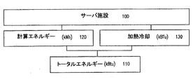
図1は、サーバ施設100におけるエネルギー消費の主要な部分を示す。トータルエネルギー110は、計算目的に用いられる電力120と、加熱冷却機能に用いられる電力130との和である。環境に基づく電力管理は、これらの主要な消費エリアを用いてトータルエネルギー使用を適応的に最小化する。繰り返しの解析は、アセット情報からのサーバ及びネットワークハードウェア構成によって消費されるトータル電力の初期的な指標を計算することによって開始される。アセットとは、サーバ、ルータ、スイッチ、冷却ユニット、ラック、センサ及び電力配分パネルをカバーするインフラストラクチャの電気計算ユニットを示す。このベース計算は、その後に、冷却及び他のインフラストラクチャ要素に提供される電力によって補完される。この電気サイドの電力消費は、企業サービスにより消費される計算パワーに対して追跡され、それをサーバレベルのリアルタイム電気測定に相関させる。アセット情報及び他のコンフィギュレーション情報は、電力管理システムに直接供給されるか、又は企業レベルの施設に一般的な既存のIT管理システムから移入することも可能である。環境を意識した電力管理システム及び方法は、環境及びサーバモニタリングのために簡単化された一般的な管理インタフェース(SNMP(Simple Network Management Protocol)ウェブサービスなど)を用いて電力配分サイドとサーバ施設の消費サイドとにおける協調的な電力モニタリングを利用することによって全体的な電力使用効率を向上させる。システム及び方法は、計算ユニット毎の電力使用効率を向上させ、ラック構成、冷却ユニット、データセンタルームの熱特性などの環境コンテクストとアプリケーションロードとに基づく動的なロード配分機能のためのポリシーを提供する。動的な計算ロードバランシングポリシーは、(i)環境について最適化された位置へのサーバの配置、(ii)物理的に多様な位置への計算タスクのスケジューリング、(iii)仮想化技術を利用したバーチャル環境におけるVMotion(VMwareにより提供される物理的サーバの間のバーチャルマシーンの移動のためのユーティリティ)によって採用可能である。提案されるアプローチは、このようなバーチャル環境における電力要求を測定するのに必要とされる改良に対処する。
FIG. 1 shows the main part of energy consumption in the
調整されたフレームワークは、図示されるモニタとして示される環境及びサーバ測定エージェントにより収集される情報の効果を最大化するのに最も重要な要素である。実際には、上記要求を正確に決定できないローカルな電気最適化が扱われる。複数の企業サービスがサーバレベルで集約される環境では、それらは、各サーバの消費電力を低減するのに役立つかもしれない。しかしながら、それらは動作状態を考慮せず、サーバがサーバブレードなどの稠密な構成において構成されるときなど、これらの状態が重要である状況において効果的でない。電力消費を最小限にするため、複数の企業サービスを単一の又は少数のサーバに集約するのに加えて、環境コンテクストに基づきサーバハードウェアの最適位置を決定することが重要である。例えば、ラックに搭載された冷却ユニットを備えるサーバにより実行されるアプリケーションは、より効率の低い冷却環境の同一のサーバ上で実行される同一のアプリケーションより全体的に少ない電力しか使用しないであろう。同様に、低電力ハードドライブを備えたサーバ上で実行されるアプリケーションは、大きな電力消費又は非効率な熱放散設計によるサーバ上で実行される同一のアプリケーションより少ない電力しか使用しないであろう。ロードバランシングのためのサーバの選択は、現在のプラクティスでは、ほとんどアドホックであり、詳細な解析を伴うものでない。 A coordinated framework is the most important factor in maximizing the effect of the information collected by the environment and server measurement agent shown as the monitor shown. In practice, local electrical optimization is handled, where the above requirements cannot be accurately determined. In an environment where multiple enterprise services are aggregated at the server level, they may help reduce the power consumption of each server. However, they do not take into account operational states and are not effective in situations where these states are important, such as when the server is configured in a dense configuration such as a server blade. In order to minimize power consumption, it is important to determine the optimal location of server hardware based on the environmental context, in addition to aggregating multiple enterprise services into a single or a small number of servers. For example, an application executed by a server with a cooling unit mounted in a rack will use less overall power than an identical application running on the same server in a less efficient cooling environment. Similarly, applications running on servers with low power hard drives will use less power than identical applications running on servers with high power consumption or inefficient heat dissipation designs. The choice of server for load balancing is mostly ad hoc in current practice and does not involve detailed analysis.
電力管理における最も重要なチャレンジは、グローバルに最適化されたロードバランシング及びコントロールのための必要とされる精度によって、サービスに関する計算処理パワーと電力消費とを相関させるための構成要素の欠落である。単一位置環境をモニタリングすることが必要とされるチャレンジに加えて、ITサービスと今日の企業とは、典型的には、地理的に遠隔地に配置され、人的、時間的及び物質的リソースのより良好な利用である。これらの地理的変数は考慮されず、このような能力に対処するための包括的な手段の欠落のため、電力動作プロファイルを提供しない。複数の地理空間的位置に対して企業サービスが提供されるため、企業サービスのグローバルコンテクスト内における企業レベルでの電力管理及び計算処理動作の何れにおける協調を含むかが重要である。全体的な電力使用の最適化は、協調的なフレームワーク、システマティック処理及び制御要素が、グローバル電力管理決定のための環境の設定可能かつ適応的なモニタリング及び継続的な解析によって、物理的位置と論理的位置(アプリケーションとサーバクラスタ又はバーチャルマシーンとして)との双方における企業計算ロードを分散させることを要求する。 The most important challenge in power management is the lack of components to correlate computational power and power consumption for services with the required accuracy for globally optimized load balancing and control. In addition to the challenges required to monitor a single location environment, IT services and today's enterprises are typically geographically located remotely, with human, temporal and material resources Better utilization of These geographic variables are not considered and do not provide a power operating profile due to the lack of comprehensive means to address such capabilities. Since enterprise services are provided for multiple geospatial locations, it is important to include coordination in enterprise-level power management and computing operations within the global context of enterprise services. The optimization of overall power usage is based on collaborative frameworks, systematic processing and control elements, which are linked to physical locations through configurable and adaptive monitoring and continuous analysis of the environment for global power management decisions. Require enterprise computing load to be distributed both at logical locations (as applications and server clusters or virtual machines).
サーバモニタリングツール及び装置は、エージェント又は非エージェントベース技術を利用して、サーバハードウェアにおいて運用されるオペレーティングシステムに主として依存する異なる機構を利用して、各サーバ上で実行される各アプリケーションのインスタンスの個数を決定することから始まって、アプリケーションロードを測定する。モニタリング及び測定のために利用可能な典型的なモニタリングインタフェースは、MicrosoftプラットフォームのWMI(Windows Management Instrumentation)、SNMP、ウェブサービス管理(WS−MAN)を含む。電力ユーザのアプリケーションロードを関連付けるのに必要な情報の詳細さは、標準的なインタフェースから直接計算可能でない。従って、利用可能な知的な電力計算であるこれら既存のベース指標から正しい指標を取得することが有用である。環境ベースの電力管理フレームワークは、環境ファクタ、サーバハードウェア特性、オペレーティングシステムオーバヘッド及び企業サービスを提供するための実行中のアプリケーションに基づき、予測される電力ユニットの消費の精度を向上させるため、異なる機構(RaritanのコマンドセンタNOC、RaritanのKiraなどのベースボード管理コントローラ、Raritan Dominion PXなどの電力環境モニタリング装置を含む)からの処理レベル情報における制約に対処する。以下に示されるように、第1レベルの電力指標は、サーバハードウェアとサーバ内に設置された電源ユニットとから取得され、第2レベル電力指標は、サーバ内で実行されるオペレーティングシステムとアプリケーションとから取得される。第3レベルの指標は、実際の企業の利用、コンフィギュレーション、トポロジー、熱活動及び電力使用の長期のモニタリングから計算される。 Server monitoring tools and devices use agent or non-agent based technology to utilize different mechanisms that depend primarily on the operating system running on the server hardware, and for each application instance running on each server. Start with determining the number and measure the application load. Typical monitoring interfaces available for monitoring and measurement include the Microsoft Platform's Windows Management Instrumentation (WMI), SNMP, Web Service Management (WS-MAN). The details of the information required to associate the power user's application load are not directly computable from the standard interface. Therefore, it is useful to obtain the correct indicator from these existing base indicators that are available intelligent power calculations. Environment-based power management frameworks differ based on environmental factors, server hardware characteristics, operating system overhead and running applications to provide enterprise services, to improve the accuracy of expected power unit consumption Address constraints in processing level information from mechanisms (including baseboard management controllers such as Raritan's command center NOC, Raritan's Kira, and power environment monitoring devices such as Raritan Dominion PX). As shown below, the first level power index is obtained from the server hardware and a power supply unit installed in the server, and the second level power index is determined from the operating system and application running in the server. Obtained from. Third level metrics are calculated from long-term monitoring of actual enterprise usage, configuration, topology, thermal activity and power usage.
サーバモニタリング装置と電気環境モニタリング装置とが別々に設置され、独立して維持される電力管理処理における他の制約は、これらの測定のスネーキングキャリブレーションとこれらの測定値の調整とを相対的に困難にする。環境を意識した電力管理システム及び方法は、サーバと環境モニタリングとを統合し、指標の協調的な収集及び処理を提供し、グローバルレベルにおける最適化の範囲を向上させる。測定装置と分散されたデータの収集との互換性を向上させるため、CIM(Common Information Model)が提案され、当該CIMのプロファイルをサポートする管理インタフェースが推奨される。インテリジェントプラットフォーム管理インタフェース(IPMI)は、このような1つの標準的なRaritan Bay sport管理コントローラ(KIRA)であり、ドミニオンPXは、電力最適化アプリケーションに適したものにするIPMIインタフェースをサポートするモニタリング及び管理装置のいくつかの具体例である。 Other constraints in the power management process where the server monitoring device and the electrical environment monitoring device are installed separately and maintained independently make it relatively difficult to calibrate these measurements and calibrate these measurements. To. Environmentally aware power management systems and methods integrate servers and environmental monitoring, provide coordinated collection and processing of indicators, and improve the scope of optimization at the global level. In order to improve the compatibility between the measurement device and the collection of distributed data, a CIM (Common Information Model) is proposed, and a management interface that supports the profile of the CIM is recommended. Intelligent Platform Management Interface (IPMI) is one such standard Raritan Bay sport management controller (KIRA), Dominion PX monitoring and management supporting IPMI interface making it suitable for power optimization applications Fig. 2 is some examples of apparatus.
環境を認識した電力管理フレームワークはまた、仮想的かつ物理的なサーバ環境に適用される。特に、仮想化技術は、協調的な電力管理を簡単化するのに役立つ動的なロードバランシング処理を提供する。後述されるように、物理的なサーバ施設と共にバーチャルなサーバ施設が提案及び採用される。 An environment aware power management framework is also applied to virtual and physical server environments. In particular, virtualization technology provides a dynamic load balancing process that helps to simplify collaborative power management. As will be described later, a virtual server facility is proposed and adopted together with a physical server facility.
プログラムされた期間中にサーバの計算パワーの指標と電力測定値を収集するのに必要な装置に加えて、当該情報の同期は、双方の利用サプライの正確な関連性と低京都に対して明確に決定される必要がある。管理コントローラ及び電力最適化(330)システムは、各種時間インターバルとの複数のインタフェースを介し収集されたデータセットをオーダ及びグループ化するのに必要なコンポーネントをサポートする。情報パートは、測定値のローカルかつ短期のバーストと異なる長期の傾向を計算する。このような場合、管理コントローラは、必要に応じてメンテナンスサイクルとの間の異なるサンプリングインターバルにおいて測定値を収集するのに必要なデータ収集装置を構成する。 In addition to the equipment required to collect the server's computational power metrics and power measurements during the programmed period, the synchronization of this information is clear to the precise relevance of both used supplies and low Kyoto. Need to be determined. The management controller and power optimization (330) system supports the components necessary to order and group data sets collected through multiple interfaces with various time intervals. The information part calculates long-term trends that differ from local and short-term bursts of measurements. In such cases, the management controller configures the data collection device necessary to collect measurements at different sampling intervals between maintenance cycles as needed.
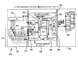
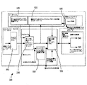
図2を参照するに、協調的な電力管理サーバ施設、データセンタ及び他の構成を利用したシステム200が示される。システム200は、管理モニタリング装置15に接続されるサーバ205,210を有する。サーバ215,210は、例えば、サーバアプリケーション、データベースアプリケーション、ウェブアプリケーション、企業アプリケーションを運用するオペレーティングシステムなどを含む何れかのハードウェア及びソフトウェア構成における何れかの計算装置であってもよい。管理モニタリング装置15は、RaritanのコマンドセンタNOC又は他の同様の装置であってもよい。サーバ205,210はまたそれぞれ、電力管理装置220,225に接続される。電力管理装置220〜225は、RaritanのドミニオンPX又は他の何れかのインテリジェント電力管理装置であってもよい。管理モニタリング装置215と電力管理装置225とはさらに、クライアントインタフェース235によってユーザにアクセス可能なモニタリング制御解析装置230に接続される。
Referring to FIG. 2, a
環境を意識した電力管理システム及び方法は、電力管理フレームワークのための構成ブロックとして上記管理コンポーネントを利用する。特に、管理モニタリング装置215は、サーバ上で実行されるリアルタイムのオペレーティングシステムとアプリケーションを決定する。さらに、管理モニタリング装置215は、各サーバ上でリアルタイムにオペレーティングシステムとアプリケーションのモニタリングを決定する。さらに、管理モニタリング装置215は、RaritanのKira装置などの埋め込みモジュール又はパーツとして利用可能なベースボード管理コントローラのハードウェアを用いてサーバハードウェアパラメータをモニタリングする。電力サイクルイベントやCPU温度を含むこれらのパラメータは、企業アプリケーションによって生成される計算ロードとCPU利用とに相関する追加的なレベルの電力指標を提供する。電力管理装置225は、有線及び無線センサ装置による環境データ(主として、温度、気流及び湿度)と同様に、各接続装置により使用される電力の情報を収集する。この環境モニタリング統合は、冷却ユニットにおけるエネルギー要求として計算ロード及び周囲の状態に拡大する。この対立的なモードは、冷却サプライにより消費されるレキシカル電力(lexical power)にその後に影響を与える熱エネルギーを生成する電力に影響を与える。データセンタ内の環境状態は、冷却ユニットの効率性に影響を与え、データセンタの動的モデルへのローカル化パラメータを含むことを必要にする。外部の環境状態はまた、所望の動作温度のクリニックインデンティング(clinic indenting)ユニットを動作させることを必要とし、モデルに搭載されるべきである。
Environmentally aware power management systems and methods utilize the management component as a building block for a power management framework. In particular, the
これらの構成要素と電力最適化の相互作用は、図2において詳述される。このシナリオでは、企業アプリケーションは中央処理エンジン(メインコントローラ)実行制御解析装置230により計算される動作プロファイルに従って分散される。すなわち、企業アプリケーションは、それの効率性、電力及び熱プロファイル、ラック内の位置、サーバルーム又は施設内の位置並びに環境状態に基づき、特定のサーバに置いて実行されるようスケジューリングされる。装置230の処理ロジックは、共通のモニタに接続される(又は電力管理装置220,225に統合される)環境センサから環境状態と、電力管理装置220,225から直接利用可能な測定電力使用とを収集する。230によりITサービスのための最適化された動作プロファイルをヒューリスティックに導出し、フレームワークは以下を考慮する。
The interaction between these components and power optimization is detailed in FIG. In this scenario, enterprise applications are distributed according to an operational profile calculated by the central processing engine (main controller)
第1に、交流(AC)電力をサーバハードウェア内で使用される直流(DC)電力に変換する電源ユニットの電流引き込み効率性。この情報は、IT技術におけるアセットデータとして知られるコンフィギュレーション管理データベース(CMDB)から取得される。アセット情報は、ハードウェアにより引き込まれる最大電力と、それの物理的設計と機能的特徴とに基づく適切な動作状態に必要な入口及び出口温度とを記述するネームプレートデータを含む。コンポーネントレベル情報に加えて、ラックの物理的位置、冷却システムからのサーバの相対距離及びラックの方向がまた、利用可能である場合、CMDB又は他のデータソースからシステムに提供される。 First, the current draw efficiency of a power supply unit that converts alternating current (AC) power into direct current (DC) power used in server hardware. This information is obtained from a configuration management database (CMDB) known as asset data in IT technology. Asset information includes nameplate data that describes the maximum power drawn by the hardware and the inlet and outlet temperatures required for proper operating conditions based on its physical design and functional characteristics. In addition to the component level information, the physical location of the rack, the relative distance of the server from the cooling system, and the orientation of the rack are also provided to the system from the CMDB or other data source, if available.
第2に、サーバ上で実行されるオペレーティングシステムとアプリケーションとによるベースレベル電力ガーメント(base level power garment)。これは、オペレーティングシステムの実装に加えて、中央処理ユニット又はCPU、ランダムアクセスメモリ、ハードディスク及び他のリソースの利用に依存する。この情報は、典型的には、ITインフラストラクチャシステムから移入され、ベースボード管理コントローラ(BMC)に自動収集される。 Second, base level power garment with operating system and applications running on the server. This depends on the use of a central processing unit or CPU, random access memory, hard disk and other resources in addition to the operating system implementation. This information is typically populated from the IT infrastructure system and automatically collected by the baseboard management controller (BMC).
第3に、環境及び時間コンテクスト内の企業計算サービスの実際の利用。このプロセスレベルの指標は、メインコントローラから計算されるようなインターバルにおけるインタフェースからのWMI及びSNMPを介しモニタリング装置15により取得される。 Third, the actual use of enterprise computing services within the environment and time context. This process level indicator is obtained by the monitoring device 15 via WMI and SNMP from the interface at intervals as calculated from the main controller.
各種装置からの情報と電力要求との相関の精度を向上させるため、測定データは、装置230内で実行されるクロックサーバに同期される。何れかの装置から取得される測定データのシーケンシング処理は、さらなる処理のための格納前の相対的なイベント発生の到着時間に基づき確認される。同期能力に加えて、ウェブサービス機能は、装置230において実行される処理エンジンと情報プロバイダサービスとの間の検出及び通信を自動化する。モニタリング及びデータ収集の開始前、不適切に登録されたすべての測定装置は、イベントをそれのコンテクストにより良好に解釈するため検出される必要がある。動作状態のコンテクストは、測定にとって重要である。例えば、ロードの少ない環境のSea RACコンピュータルームエアコンユニットの電力使用は、ロードの高い動作状態の測定とは異なって扱われるべきである。システム全体を通じて受信されるデータは、グローバルレベルの動作コンテクスト内で解釈される。モニタデータは受信機にアクセス可能であり、通常のシナリオでは、それはシステムのメインコントローラである。1以上の装置からデータを受信することに失敗した場合、管理コントローラは、次のレベルの指標又は導出された指標を調整し、システムへの以前のコンテクスト又は以前のデータ取得が通常動作に戻る。ウェブサービスを利用した標準的なインタフェースは、スケーラブルな再設定可能な企業プラットフォームに適合し、提案されるアプローチは、それの既存のインフラストラクチャに容易に採用可能である。情報技術サービスのための従来の電力管理は、ネットワークを介し協調的な処理の各機能を提供するものでなく、このため、電力使用におけるインフラストラクチャ及び計算装置におけるロードバランシングを享受することができない。本発明のシステム及び方法は、各装置においてネットワークアウェアサービスを提供することによって、この制約に対処する。これは、複数のユニットにおける移行処理の異なるユニット間のリアルタイムな同期を実現する。ネットワーク対応ウェブサービス技術は、アプリケーションの動作、短期の不具合又は置換不可なクラッシュがある複雑な環境において価値がある受動的及び能動的電力モニタリングをサポートする。ウェブサービスは、本ケースでは、データ測定装置、データを処理するデータ受信機であるピア・ツー・ピアシステムの間の加入方法による再設定を可能にする日付の設定を提供することが可能である。
In order to improve the accuracy of the correlation between information from various devices and power requirements, the measurement data is synchronized to a clock server running in the
電力(及び冷却)が極めて重要である場合、サーバレベルの電力モニタリングが、検査、容量プランニング、熱評価及びパフォーマンス向上のため、情報技術管理に特に効果的である。これらのシナリオは、電力使用とサーバ上のモニタリング動作が所定の及び/又は動的な電力ポリシーに基づきロードを再スケジューリングする必要性を決定することを実質的に要求する。動的な電力管理ポリシーは、システムに格納されるか、又は外部のネットワーク管理システムから参照される。電力プロファイルの基本レベルは、制御方法が提供される場合、オペレーティングシステムレベルとACPI(Advanced Configuration and Power Interface)においてサポートされる。提案されるアプローチは、ACPIを含む何れかの電力プロファイルに適用され、各種のプロファイルについて適切な指標を利用する。ACPIを利用した現在の電力ポリシーは、無停電電源生成装置と同様に、他のソースからの電力の利用性に基づき計算ユニットに供給される信頼できる電力に着目される。 Where power (and cooling) is critical, server level power monitoring is particularly effective for information technology management for inspection, capacity planning, thermal evaluation and performance improvement. These scenarios substantially require that power usage and monitoring operations on the server determine the need to reschedule the load based on predetermined and / or dynamic power policies. The dynamic power management policy is stored in the system or referenced from an external network management system. The basic level of the power profile is supported at the operating system level and ACPI (Advanced Configuration and Power Interface) if a control method is provided. The proposed approach applies to any power profile, including ACPI, and utilizes appropriate metrics for the various profiles. The current power policy using ACPI focuses on the reliable power supplied to the computing unit based on the availability of power from other sources, similar to the uninterruptible power generation device.
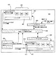
図3を参照するに、本発明によるサーバ企業又はデータセンタのためのインテリジェント電力モニタリングシステム300のフレームワークが示される。第1段階301において、ターゲットサーバ310への電力配分ユニット(PDU)として動作する電力管理装置305としてのシステム300は、ユーザがターゲットサーバ310又はPDUレベル(配分されるトータル電力)の電力消費の正確な観点を提供する出口レベルにおける電力を測定することを可能にする。既存の電力配分ユニットの大部分は、サーバレベルにおける電力モニタリングには十分でない可能性があるラックレベル又はブランチ回路レベルの電力測定値を測定する。第2段階302において、管理モニタリング装置315は、WMI、SNMP又はWS−MANクライアントインタフェースを利用して、ターゲットサーバからのITサービス利用情報を収集し、それをモニタ331のデータアプリケーションレイヤ325に提供する。さらに、IPMIクライアントインタフェース320は、データ取得レイヤ325の電力管理装置305から情報を収集する。これは、直交的な指標であり、最大、最小及び平均電力消費の評価を提供する。モニタ331はまた、閾値を入力し、モニタ331に警告するコンフィギュレーションスクリプティングインタフェース333に接続される。本開示では、モニタは、サーバ側指標を取得する装置(オペレーティングシステム、CPU温度、アプリケーションインスタンスなど)と共に、電気側指標(電力使用、温度、気流、湿度など)を取得する装置からの測定値をモニタリングするソフトウェアコンポーネントを参照する。これは、システムのデータインタフェースレイヤであり、メインコントローラ330から設定可能である。メインコントローラ330は、ポーリングインターバル、イベント受信機構及び装置トポロジー及び通信インタフェースを規定可能である。
Referring to FIG. 3, a framework of an intelligent
次に、データ取得レイヤ325は、それをデータベース340に提供する。データベース340は、解析により構成されるフィードバックに接続され、アプリケーションサーバ又はウェブサーバ350に接続されるユーザインタフェース(可視化及び相互作用)レイヤ335のための処理された情報を適用する。第3段階303では、アプリケーションサーバ又はウェブサーバ350は、トレンド解析、キャパシティ解析、効率性指標を含む処理された情報をクライアント側のJavaクライアント又はウェブブラウザ355と交換する。
The
このフレームワークの報告及び公表ロジックは、エネルギー検査のための警告又は報告の何れかの形式により2種類の情報配信を含む。図3に示されるように、フレームワークから導出された指標は、キャパシティデータ収集336から厳密な最適化345に基づく推定までの範囲である。解析エンジンの出力の報告は、データセンタ及び環境コンテクストにおいて実行中のアプリケーションに、個別のサーバの効率性と関連性とを含むデータセンタ効率性指標を提供可能である。出力はまた、トレンドを追跡するためのデータセンタ電力使用のベースモデル及び適応的学習のサービスを提供する。これらの出力は、所望の企業サービス、サーバハードウェア及びソフトウェアテロリスト特性、冷却及び換気施設を含むデータセンタ環境パラメータを考慮して、電力消費を最適化するのに利用可能である。このフレームワークの長所は、設定可能な電力モニタリングロジックと、ヒューリスティック解析に基づくIT企業サービス従属性の抽出である。
The reporting and publication logic of this framework includes two types of information distribution, either in the form of warnings or reports for energy testing. As shown in FIG. 3, the metrics derived from the framework range from
図4を参照するに、バーチャルマシーン実現形態における協調的な電力管理を利用するシステム400が示される。システム400は、クライアントインタフェース135を介しユーザによりアクセス可能な制御解析装置430に接続されるサーバ405,410を有する。サーバ400,510は、VMWare又はXenなどのバーチャルマシーン環境を実現する計算装置であってもよい。一実施例では、プロバイダ407(412)は複数のバーチャルマシーン409(414)を管理する。サーバ405,410はそれぞれ、電力管理装置424,425と接続される。各サーバ405,410は、メモリ、ディスク及びネットワーク利用に関してすべてのアプリケーションレベルにおけるすべての実行中のプロセス(コンピュータパワー)及びそれらのリソース利用を有する。これは、ハードウェアリソースのための仮想化サーバにより供給されるハイパバイザAPIをモニタリングすることによって実現される。装置430は、装置405,410からこの情報を収集し、装置420,425から追加的な情報を収集する。
With reference to FIG. 4, illustrated is a
図2及び4に示される両方のシナリオでは、エネルギー消費指標は、オペレーティングシステム、ネットワーク、メモリ、ストレージ及びインフラストラクチャなどのコアサービスを処理するのに必要とされる電力に正規化される。一実施例では、アプリケーションロードは、計算及び冷却に関して政策的な電力利用を最小化するため、異なる物理的及び論理的ビンの間に高度に分散化されてもよい。 In both scenarios shown in FIGS. 2 and 4, the energy consumption index is normalized to the power required to handle core services such as operating system, network, memory, storage and infrastructure. In one embodiment, application loads may be highly distributed between different physical and logical bins to minimize policy power usage with respect to computation and cooling.
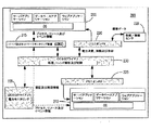
データドリブンフレームワークは、モニタリングを実行し、電気計算電力管理の動的制御のためのインタフェースを提供する。この方法は、何れか所与の時点における企業により必要とされるトータルの計算ロードの最適な配分のための基礎を提供することによって、必要とされる等しい計算パワーのコストを低減する。一般に、図5は、所与の計算ロードのための効果的な電力利用のための動作中の計算電力を計算するため、サービスコンテクストにおいて現在の動作状態を解析する電力最適化方法に関するステージを示す。判定ルールは、ITアドミニストレータとインフラストラクチャプロバイダにより設定可能な企業サービスの重要性に従って確定されてもよい。例えば、アドミニストレータは、データセンタの電力消費の合計レートに対する絶対的なリミットを設定し、電力消費リミットが満たされた場合に実行が保留されるべきアプリケーションを特定することを決定可能である。当該ステージの出力は制御ロジック状態に提供され、トータルの電力使用を最小化するため、サービス間にアプリケーションが配分される。 The data driven framework performs monitoring and provides an interface for dynamic control of electrical computational power management. This method reduces the cost of equal computational power required by providing a basis for optimal allocation of the total computational load required by the enterprise at any given time. In general, FIG. 5 shows the stages for a power optimization method that analyzes the current operating state in a service context to calculate operating power for operation for effective power utilization for a given computational load. . The decision rules may be determined according to the importance of enterprise services that can be set by the IT administrator and infrastructure provider. For example, an administrator can set an absolute limit on the total rate of data center power consumption, and can determine to identify applications that should be suspended from running if the power consumption limit is met. The output of the stage is provided to the control logic state, and applications are distributed among the services to minimize total power usage.
図5を参照するに、本発明の方法のトップレベルのフローチャートが示される。環境アプリケーションサーバ電力データが、フィルタ505に入力される。図2の装置230及び図4の装置430を介し収集されるデータのデータ量は極めて大きいため、フィルタ505は、装置230,430のフロントエンドに収容される。フィルタ505は、図2の装置220,225などから受信した電力データと相関させるのに適した政策的な電力消費コンピュータCPU電力指標に関する情報を優先順位付けするための機能を提供する。フィルタは、多数のノード及び収集装置を介し収集されたデータから、短期の詳細と共に長期のトレンドとを供給する。多数のバーチャルマシーンに共有されるCPU利用、メインメモリ、ディスクI/O及びCPUタイムスライスは、サーバハードウェア上の電力消費に対する大きな影響を有する指標の具体例である。フィルタ505の機能は、このようなリソース利用を電力を示した企業間のマッピングを実現する表現に累積することである。特に低レベルの複雑さを有する小規模なデータセンタでは、フィルタは要求されなくてもよく、リソース利用情報が使用される。
Referring to FIG. 5, a top level flowchart of the method of the present invention is shown. Environmental application server power data is input to filter 505. Since the amount of data collected through the
フィルタリングされたデータは、その後に動作モデリングモジュール510に入力される。ワークロード又は企業サービス特性は、一般的な企業サービスと一般的なサーバプラットフォームのために予め実行され、データセンタ電力使用のための基本モデルを生成する。これは、第2入力モジュール510を提供する知識ベース515に格納される。サーバの合成された特性とアプリケーションの組み合わせのベースモデリングはまた、所与の時点におけるサーバ処理の利用性の電力を処理するのに必要なデータを低減するのに役立つ。ワークロード特性は、アセットデータベースから取得されたハードウェアパラメータに正規化された。モジュール510への第3入力は、パラメータにおいて現在の動的モデル情報を提供するデータベース20である。
The filtered data is then input to the
モジュール510は、必要に応じてデータベースを更新するのに利用される現在のデータセンタコンフィギュレーション及び計算ロードに関する情報をデータベース520に送信する。現在状態情報はまた、それを利用して動的モデルにより予測される電力使用及び環境指標(周囲の温度など)を完了するパスター電力指標計算モジュール525である。電力消費測定モジュール530は、モジュール510からの各種サーバ間へのアプリケーションロードの既存の分散化に関する情報を取得し、モジュール525から予測された電力環境指標を取得する。モジュール530は、時間に正確で相関的な方法により、装置220,225などから、モニタリング入力への実際の電力、熱及び他の環境状態に関する情報を取得する。予測されたデータが実際のデータの規定された許容リミット内である場合、動的モデルが確認され、そうでない場合、情報は、データベース520の動的モデリングアルゴリズムパラメータを更新及び規定するためのフィードバックを提供するトレンド解析モジュール535に出力される。
最終ステップとして、動的モデリングは、電力使用の最適化のため、サービス間へのロードの緩和が必要か決定するため、現在のアプリケーションに適用される。共通の環境ファクタとサーバのハードウェア及びソフトウェア特性の適用に基づきモデルの予測電力使用が与えられると、当該決定をする既知の方法が多数存在する。例えば、シンプルなアプローチは、既存の環境状態の下での計算ロードのインクリメントのための予測された増分的な電力引き込みに基づきサーバを順位付けし、計算ロードの予想されるスケジュールに基づきアプリケーションを順位付けすることであろう。大きなロードを有するアプリケーションから始めて、当該プロセスは、アプリケーションのインスタンスをまず最も効率的なサーバに配分し、サーバの最大コンペティションに到達すると、次に最も効率的なサーバに移行する。このアプローチは、妥当な結果をもたらし、シンプルかつ迅速であるという効果を有する。それはしばしば、サブ最適な割当てをもたらす。好適な実施例のより良好なアプローチは、ホームネットワークにおいて用いられるバックプロパゲーション学習アルゴリズムに類似した処理を用いて、最小数のルールしか決定しない。何れのネットワークも、学習に基づきニューロンセットと各ニューロン間の相互接続とによるコンピュータアルゴリズムを利用した人間の学習及び知能をモデル化することを試みた人工知能方法に類似しない。アプリケーションロードの配分が実現されるか、又は環境状態インフラストラクチャへの調整が必要であると解析により結論付けされると、1)加熱冷却コントロール540と、2)所望の変更を実現するためサーバ及びアプリケーションロードバランスコントロール545とに送信される。
As a final step, dynamic modeling is applied to current applications to determine if load mitigation between services is necessary to optimize power usage. Given the predictive power usage of a model based on the application of common environmental factors and server hardware and software characteristics, there are many known ways to make that determination. For example, a simple approach ranks servers based on predicted incremental power draws for compute load increments under existing environmental conditions, and ranks applications based on the expected schedule of compute loads. It will be attached. Starting with an application that has a large load, the process first allocates instances of the application to the most efficient server and then moves to the next most efficient server when the server's maximum competition is reached. This approach has the effect of providing reasonable results and being simple and quick. It often results in sub-optimal assignments. A better approach of the preferred embodiment uses a process similar to the back-propagation learning algorithm used in the home network to determine a minimal number of rules. None of the networks are similar to artificial intelligence methods that attempt to model human learning and intelligence using computer algorithms with neuron sets and interconnections between neurons based on learning. Once the analysis concludes that application load allocation is realized or adjustment to the environmental infrastructure is needed, 1) heating and
一般に、エネルギー保存のため環境を探索するためのフレームワークにおける主要な構成要素は、メインコントローラ、モニタ、データベース及び解析エンジンを含む、モニタエンジンに収集されるメタデータは、管理困難であり、エネルギーデータ収集のために十分には利用されていない可能性がある。フレームワークは、電気計算エネルギー計算に関する選択された関連情報の取得及び解析を実現する初期的な実行の後にカスタマ環境を調整するインテリジェントコンフィギュレーションモジュールを提供する。フレームワークは、精度とサンプリングレートとにより必要なインターバルで測定値を収集するよう構成される。このモジュールは、企業サービスとそれの影響が取得解析ロジックに直近に追加されるような方法により設計される。フレームワーク全体は、環境の情報と共にロジックを有するか、又は外部レポジトリに統合可能である。この情報は、電気エンティティと計算パワーエンティティとの間の関連付けを適応的に追跡するため、ヒューリスティック情報において利用される。フレームワークは、動的学習又は静的インポートを介しサービス及びインフラストラクチャを収集する。この情報は、その後に、人間の精神活動に典型的なものに加えて、サービスの解析のための基礎として利用される。これは、その後の配置労力と自動化された学習に関して効率性を向上させる。フレームワークのすべての構成要素の同期は、外部のネットワークタイムサービスに関して内部タイムサーバに設定可能である。 In general, the main components in a framework for exploring the environment for energy conservation are the main controller, monitor, database and analysis engine, and the metadata collected by the monitor engine is difficult to manage and energy data It may not be fully utilized for collection. The framework provides an intelligent configuration module that coordinates the customer environment after initial execution to achieve acquisition and analysis of selected relevant information regarding electrical computational energy calculations. The framework is configured to collect measurements at required intervals depending on accuracy and sampling rate. This module is designed in such a way that enterprise services and their impact are added to the acquisition analysis logic most recently. The entire framework can have logic with environmental information or can be integrated into an external repository. This information is used in heuristic information to adaptively track the association between the electrical entity and the computational power entity. The framework collects services and infrastructure via dynamic learning or static import. This information is then used as a basis for analysis of services in addition to what is typical of human mental activity. This increases efficiency with respect to subsequent placement effort and automated learning. Synchronization of all components of the framework can be set to an internal time server with respect to external network time services.
開示されたアプローチは、各種電力使用ヒューリスティックの設定及び特徴付けのための複数の機構を利用して収集される電力マターのシステマティックな処理によって、計算利用545のためのグローバルプロファイルを生成する。動作プロファイルは、各サーバのロード量、計算ロードを収容するサーバの位置、及び要求されるスケジュールに従って冷却ユニットに提供される電気ユニットを指定する。本方法は、環境全体における電力最適化の精度を最大化するため、プロセスレベルでのエネルギー消費をモデル化する。ウェブサービスベースのアプローチは、分散化された企業に対して良好に機能し、通信フレームワークは、中央電力管理システムから離れた位置における動的なロード状態とロードバランシング処理を収集するため、複数レベルの集約的な制御を介し階層的に拡張される。
The disclosed approach generates a global profile for
図5が単なる例示であり、他のプログラムエントリ及びイグジットポイント、タイムアウト機能、エラーチェックルーチンなど(図示せず)が典型的なシステムソフトウェアにより通常に実現されることが理解される。また、システムは、埋め込みシステムにおいて連続的に実行されるよう実現可能であることが理解される。従って、スタートブロックとエンドブロックとは、メインプログラムに統合され、連続的なシステム処理をサポートするため必要に応じて呼び出し可能なコードの一部の論理的なスタート及びエンドポイントを示すためのものである。本発明のこれらの態様の実現は、ここでの開示に基づき当業者の理解の範囲内で容易に明らかである。 It will be appreciated that FIG. 5 is merely exemplary and that other program entries and exit points, timeout functions, error checking routines, etc. (not shown) are typically implemented by typical system software. It will also be appreciated that the system can be implemented to run continuously in an embedded system. The start block and end block are therefore integrated into the main program and indicate the logical start and end points of the code that can be called as needed to support continuous system processing. is there. Implementation of these aspects of the invention will be readily apparent to those of ordinary skill in the art based on the disclosure herein.
上述されるような一例となるネットワーク環境は、相互接続されたコンピュータ、サーバ、アプリケーション及び他の装置のネットワークにおいて適用可能であり、上述された方法に関して利用可能である。コンピュータは、1以上のピアとの論理的接続を利用するネットワーク化された環境において一般に動作する。本方法に関して利用されるコンピュータは、パーソナルコンピュータ8、サーバ、ルータ、ネットワークPC、ピア装置又は他の一般的なネットワークノードであってもよく、典型的には、上述された多数の又はすべての要素を含む。これらの接続は、以下に限定することなく、ローカルエリアネットワーク(LAN)、ワイドエリアネットワーク(WAN)及び、オフィス、企業ワイドコンピュータネットワーク、イントラネット及びインターネットにおいて一般的な他のネットワーク環境を含む。図示されるネットワーク接続は一例であり、コンピュータ間の通信リンクを確立するための他の手段がまた利用されてもよいことが理解されるであろう。図示のため、プログラム及びオペレーティングシステムなどの他の実行可能なプログラムコンポーネントが個別のブロックとして示されるが、このようなプログラム及びコンポーネントはコンピュータの異なる記憶要素において各時点で存在し、コンピュータのデータプロセッサにより実行されることが認識される。ハードウェアとソフトウェアの各種組み合わせは、本発明の教示を実行するため利用可能である。コンピュータ又は計算装置は、典型的にはプロセッサを含む。プロセッサは、典型的には、マイクロプロセッサなどのCPUを含む。CPUは、一般に算術及び論理処理を実行する算術論理ユニットALUと、メモリから命令(コードなど)を抽出し、それらを復号化及び実行し、必要に応じてALUを呼び出す制御ユニットとを有する。ここで用いられるメモリは、限定することなく、1以上のメモリ(RAM)、ROM(Read−Only Memory)、PROM(Programmable ROM)、EPROM(Erasable PROM)、EEPROM(Electrically PROM)チップを意味する。メモリは、プロセッサを有する集積ユニットの内部又は外部にあってもよい。メモリは、好ましくは、プロセッサにより実行可能な命令のコード又はシーケンスなどのコンピュータプログラムを格納する。 The example network environment as described above is applicable in a network of interconnected computers, servers, applications and other devices, and can be used with respect to the methods described above. Computers typically operate in a networked environment that utilizes logical connections with one or more peers. The computer utilized in connection with the method may be a personal computer 8, a server, a router, a network PC, a peer device or other common network node, typically a number or all of the elements described above. including. These connections include, but are not limited to, local area networks (LANs), wide area networks (WANs), and other network environments common in offices, enterprise wide computer networks, intranets and the Internet. It will be appreciated that the network connections shown are exemplary and other means of establishing a communications link between the computers may also be utilized. For purposes of illustration, other executable program components, such as programs and operating systems, are shown as separate blocks, but such programs and components exist at different points in the computer's different storage elements and may be It is recognized that it will be executed. Various combinations of hardware and software can be used to implement the teachings of the present invention. A computer or computing device typically includes a processor. The processor typically includes a CPU such as a microprocessor. The CPU generally includes an arithmetic logic unit ALU that performs arithmetic and logical processing, and a control unit that extracts instructions (codes and the like) from the memory, decodes and executes them, and calls the ALU as necessary. The memory used here means, without limitation, one or more memories (RAM), ROM (Read-Only Memory), PROM (Programmable ROM), EPROM (Erasable PROM), EEPROM (Electrically PROM) chip. The memory may be internal or external to the integrated unit having the processor. The memory preferably stores a computer program such as a code or sequence of instructions executable by the processor.
上述されるように、アプリケーションロードの再配分又は環境調整インフラストラクチャへの調整が求められると解析が結論付ける場合、適切な命令が、1)加熱冷却コントロール540と、2)所望の変化を実現するためサーバ及びアプリケーションロードバランシングコントロール545とに送信される。APCI対応ハードウェア及びOSは、効率的なエネルギー消費を介しエネルギーコストを低減する他の方法を可能にする。具体的には、装置、マザーボード、チップセット及びCPUレベルにおけるエネルギー消費量を制御する技術がまた、上述されたステップ540及び545に加えて利用されてもよい。多くのテクノロジー企業は、ACPIとの準拠を実現している。上述されるように、ACPIは、プロセッサレベルにおける電力管理を実現するための現在のオープンな規格である。ACPIは、それの最も基本的なものにおいて、シュリンクラップ(shrink−wrap)OSコードがこのようなハードウェアインタフェースを利用することを可能にしながら、フレキシブルなハードウェア実現を可能にするのに十分な抽象性においてハードウェアインタフェースを記述する方法である。OSPM(Operating System−directed Power Management)は、OSが中心的な役割を担う電力(及びシステム)管理のモデルであり、グローバル情報を用いて対象となるタスクのシステム動作を最適化する。ACPIハードウェアは、OSPMをサポートするのに必要な機能と、ACPI記述テーブルを用いて記述される機能とのインタフェースととを備えるコンピュータハードウェアである。
As described above, if the analysis concludes that application load redistribution or adjustment to the environmental conditioning infrastructure is required, appropriate instructions will achieve 1) heating and
オペレーティングシステムは、システム、プロセッサ又は装置の特定の動作を規定するシステム、プロセッサ又は装置の処理モードである各種ACPIにより規定される状態を選択することによって、ACPIハードウェアとやりとりする。未完成の状態リストが以下に与えられる。これら各種状態は、例えば、Advanced Configuration and Power Interface Specification(Revision 3.0b October 10,2006)などに記述される。
・利用するのに可視的であり、4つの状態G0,G1,G2,G3に分割される全体的なシステム状態であるグローバルシステム状態;
・グローバルシステム状態G1(S5を除く)内にあって、S1,S2,S3,.S4,S5に分割されるスリーピング状態;
・4つの状態D0,D1,D2,D3に分割され、各装置により変更されるユーザに通常は可視的でない装置電力状態;
・グローバルシステム状態G内にあって、C0,C1,C2,C3,C4に分割されるCPUスリープ状態としても知られるCPU電力状態;
・アクティブであるときCPU/装置の電力管理を制御し、ワークロードに依存してクロックスピードと電圧変化とを通常含み、CPIに依存する状態数を有するCPU/装置パフォーマンス状態;
・温度が閾値を超えるとCPUを低パフォーマンス状態にスロットルし、TM1スロットルがデューティサイクルを変更することによって実行され、TM2スロットルがクロックスピード又はコア電圧(P状態)を変更することによって実行されるCPU温度モニタ;
電力管理とCPU又は装置により使用される電力量の決定のため、S1−S4が2〜30秒のウェークアップ遅延を決定することによって、G1状態又はスリーピング状態を確立することは、明らかに有用である。さらに、各種CPU電力状態(C−state)はまた、CPUレベルにおけるオペレーティングシステムの調整電力を有するのに有用な方法を可能にする。C0状態はベースラインであり、この状態においてプロセッサは命令を実行する。C1状態は、最も小さな遅延を有する。この状態におけるハードウェア遅延は、オペレーティングシステムがそれを利用するか否か決定する際に状態の遅延特徴を考慮しないだけ十分低いものでなければならない。非実行電力状態にプロセッサを置くのとは別に、当該状態は他の何れのソフトウェアによる可視的な効果を有しない。これは、10nsの大きさのオーダを有するウェークアップ時間によるアセンブリ命令“halt”を利用することによって、実際の実行では実行される。C2状態は、C1状態に対して電力セービングを向上させる。この状態のワーストケースのハードウェア遅延は、ACPIシステムファームウェアを介し提供され、オペレーティングシステムは、当該情報を利用してC1状態がC2状態の代わりに利用されるべき時点を決定することができる。C2からC0への遷移時間は、100ナノ秒の大きさのオーダであり、当該処理は、プロセッサコアクロック及びプラットフォームI/Oバッファをゲート処理することによって、プロセッサレベルにおいて実現される。プロセッサを非実行電力状態に置くのとは別に、当該状態は他のソフトウェアによる可視的な効果を有しない。C3状態は、C1及びC2状態に対して電力セービングを向上させる。C3状態では、バスクロックとPLLとがゲート処理される。ウェークアップ時間は、現在は50μsのオーダである。当該状態のワーストケースのハードウェア遅延は、ACPIシステムファームウェアを介し提供され、オペレーティングシステムは、当該情報を利用して、C3状態の代わりにC2状態が利用されるべき時点を決定することができる。C3状態では、プロセッサのキャッシュは状態を維持するが、スヌープを無視する。オペレーティングソフトウェアは、キャッシュがコヒーレンシを維持することを保障するためのものである。
The operating system interacts with the ACPI hardware by selecting states defined by various ACPIs that are processing modes of the system, processor or device that define the specific operation of the system, processor or device. An unfinished state list is given below. These various states are described in, for example, Advanced Configuration and Power Interface Specification (Revision 3.0b October 10, 2006).
A global system state that is visible to use and is an overall system state divided into four states G0, G1, G2, G3;
In the global system state G1 (except S5), S1, S2, S3,. Sleeping state divided into S4 and S5;
A device power state that is divided into four states D0, D1, D2, D3 and that is not normally visible to the user as modified by each device;
CPU power state, also known as CPU sleep state, which is in global system state G and divided into C0, C1, C2, C3 and C4;
A CPU / device performance state that controls power management of the CPU / device when active, typically includes clock speed and voltage changes depending on the workload, and has a CPI-dependent number of states;
CPU that throttles the CPU to a low performance state when the temperature exceeds a threshold, the TM1 throttle is executed by changing the duty cycle, and the TM2 throttle is executed by changing the clock speed or core voltage (P state) Temperature monitor;
For power management and determination of the amount of power used by the CPU or device, it is obviously useful to establish a G1 state or sleeping state by S1-S4 determining a wakeup delay of 2-30 seconds. . In addition, the various CPU power states (C-states) also allow a useful way to have operating system adjustment power at the CPU level. The C0 state is a baseline, in which the processor executes instructions. The C1 state has the smallest delay. The hardware delay in this state should be low enough not to consider the state's delay characteristics when the operating system decides whether to use it. Apart from placing the processor in a non-executable power state, the state has no visible effect by any other software. This is performed in actual execution by utilizing an assembly instruction “halt” with a wake-up time having an order of magnitude of 10 ns. The C2 state improves power saving over the C1 state. The worst case hardware delay of this state is provided via the ACPI system firmware, and the operating system can use this information to determine when the C1 state should be used instead of the C2 state. The transition time from C2 to C0 is on the order of 100 nanoseconds, and the processing is realized at the processor level by gating the processor core clock and platform I / O buffers. Apart from placing the processor in a non-executable power state, this state has no visible effect by other software. The C3 state improves power saving over the C1 and C2 states. In the C3 state, the bus clock and the PLL are gated. The wake-up time is currently on the order of 50 μs. The worst case hardware delay for that state is provided via the ACPI system firmware, and the operating system can use this information to determine when the C2 state should be used instead of the C3 state. In the C3 state, the processor cache maintains state but ignores snoops. The operating software is to ensure that the cache maintains coherency.
さらに、装置及びプロセッサパフォーマンス状態(Px状態)は、アクティブ/実行中の状態C0及びD0内の電力消費能力状態である。Px状態が、以下で簡単に規定される。P0−装置又はプロセッサが当該状態にある間、それは自らの最大パフォーマンス能力を利用し、最大電力を消費してもよい。P1−このパフォーマンス電力状態では、装置又はプロセッサのパフォーマンス能力はそれの最大値以下に制限され、最大電力未満を消費する。Pn−このパフォーマンス状態では、装置又はプロセッサのパフォーマンス能力は、それの最小レベルにあり、アクティブ状態に留まりながら最小電力を消費する。状態nは、最大数であり、プロセッサ又は装置に依存する。 Furthermore, the device and processor performance states (Px states) are power consumption capability states in the active / running states C0 and D0. The Px state is briefly defined below. While the P0-device or processor is in that state, it may utilize its maximum performance capability and consume maximum power. P1-In this performance power state, the performance capability of the device or processor is limited below its maximum value and consumes less than maximum power. Pn—In this performance state, the performance capability of the device or processor is at its minimum level and consumes minimum power while remaining active. State n is the maximum number and depends on the processor or device.
P状態は、動的な電圧スケーリング及び動的な周波数スケーリングによって実現可能である。動的な電圧スケーリングは、コンポーネントで用いられる電圧が状況に応じて増減されるコンピュータアーキテクチャにおける電力管理技術である。電圧を低下させることは、電力消費を低下させながらプログラムランタイムを増加させることを意味する。動的周波数スケーリング(CPUスロットリングとしても知られる)は、電力を節約するためプロセッサが最大値未満の周波数で実行されるコンピュータアーキテクチャにおける技術である。 The P state can be realized by dynamic voltage scaling and dynamic frequency scaling. Dynamic voltage scaling is a power management technique in a computer architecture where the voltage used in a component is increased or decreased depending on the situation. Reducing the voltage means increasing the program runtime while reducing power consumption. Dynamic frequency scaling (also known as CPU throttling) is a technique in computer architecture where the processor is run at a frequency below a maximum value to save power.
この動的電圧及び周波数スケーリング技術(DVFS)では、CPUコア電圧、クロックレート又はその双方が、可能性のあるパフォーマンスを犠牲にして電力消費を減少させるよう変更可能である。これは、電力−パフォーマンスのトレードオフを最適化するのに利用可能である。DVFS技術は、動的な電圧スケーリングと動的な周波数スケーリングとを含む。動的な電圧スケーリングは、コンポーネントにおいて用いられる電圧が状況に応じて増減されるコンピュータアーキテクチャにおける電力管理技術である。電圧を減少させるための動的な電圧スケーリングは、不足電圧として知られる。MOSFETベースのデジタル回路は、論理状態を表すため回路ノードの電圧を用いて動作する。これらのノードにおける電圧は、通常動作中は高電圧と定電圧との間で切り替えられ、論理ゲートへの入力が遷移すると、これを構成するトランジスタがゲート出力を切り替える。回路の各ノードには、特定量の電気容量がある。この電気容量は、拡散容量の電気容量及び電気容量を接続する配線を介し主としてトランジスタなどの各種ソースから生じる。回路ノードにおける電圧の切替は、電圧に関するカーソルがないため、これに係る時間が印加される電圧に依存するため、電気容量を充電又は放電することを必要とする。より高い電圧を回路の装置に印加することによって、電気容量はより迅速に充電及び放電され、回路のより迅速な処理とより高い周波数の処理のための出力を生じさせる。状態CMOSゲートを用いてチップにより放散されるスイッチング電力は、数式C*V2*fにより決定される。ここで、Cはクロックサイクル毎にスイッチされる電気容量であり、Vは電圧であり、fはスイッチング周波数である。この数式は、現在のチップがCMOS技術のみにより実現されていないため、正確なものでないが、それは、電力消費全体が電圧に従って低下することを示す。従って、動的な電圧スケーリングが、携帯電話やラップトップコンピュータなどのバッテリ駆動装置におけるスイッチング電力消費を管理するための戦略の一部として広く利用される。定電圧モードは、CPUやDSPなどに関する電力消費を最小化するため、より低いクロック周波数に関して利用される。多くの周辺装置がまた定電圧動作モードをサポートすることに留意されたい。電圧の低下は、回路スイッチがより低速であり、当該回路が実行可能な最大周波数を生成することを意味することに留意されたい。これは、プログラム命令が発行可能なレートを低下させ、CPUバウンドを有意に成功させたプログラムセグメントのランタイムを増大させるものであってもよい。従って、電力管理と計算ロードとの間には複雑なトレードオフがある。また、レギュレータなどの一部の論理コンポーネントの効率性は温度の上昇と共に低下することに留意されたい。これは、電力使用が温度と共に増大する可能性があるためである。電力使用の増大は温度を上昇させるため、電圧又は周波数の増大はまた、上述したCMOS数式が示すよりはるかに速くシステム電力需要を増大させる可能性がある。 With this dynamic voltage and frequency scaling technique (DVFS), the CPU core voltage, clock rate or both can be modified to reduce power consumption at the expense of possible performance. This can be used to optimize the power-performance tradeoff. DVFS technology includes dynamic voltage scaling and dynamic frequency scaling. Dynamic voltage scaling is a power management technique in a computer architecture where the voltage used in a component is increased or decreased depending on the situation. Dynamic voltage scaling to reduce the voltage is known as undervoltage. MOSFET-based digital circuits operate using the voltage at the circuit node to represent the logic state. The voltages at these nodes are switched between a high voltage and a constant voltage during normal operation, and when the input to the logic gate transitions, the transistors constituting this switch the gate output. Each node of the circuit has a certain amount of capacitance. This electric capacity is generated mainly from various sources such as a transistor through the electric capacity of the diffusion capacity and the wiring connecting the electric capacity. Since switching of the voltage at the circuit node does not have a cursor related to the voltage, it depends on the voltage to be applied for a time related to this, so that it is necessary to charge or discharge the capacitance. By applying a higher voltage to the device of the circuit, the capacitance is charged and discharged more quickly, producing an output for faster processing of the circuit and higher frequency processing. The switching power dissipated by the chip using the state CMOS gate is determined by the formula C * V 2 * f. Here, C is a capacitance switched every clock cycle, V is a voltage, and f is a switching frequency. This formula is not accurate because current chips are not implemented only with CMOS technology, but it shows that the overall power consumption decreases with voltage. Therefore, dynamic voltage scaling is widely used as part of a strategy for managing switching power consumption in battery powered devices such as cell phones and laptop computers. The constant voltage mode is used for lower clock frequencies to minimize power consumption for CPUs, DSPs, etc. Note that many peripheral devices also support a constant voltage mode of operation. Note that the drop in voltage means that the circuit switch is slower and produces the maximum frequency that the circuit can perform. This may reduce the rate at which program instructions can be issued and increase the runtime of program segments that have made CPU bound significantly successful. Thus, there is a complex trade-off between power management and computational load. It should also be noted that the efficiency of some logic components such as regulators decreases with increasing temperature. This is because power usage can increase with temperature. Since increasing power usage raises temperature, increasing voltage or frequency can also increase system power demand much faster than the CMOS formula described above.
動的な周波数スケーリングは、電力を節約するためプロセッサが最大周波数未満で実行されるアーキテクチャへの技術である。再び、電圧レギュレータなどの一部の電気コンポーネントの効率性は温度の上昇と共に減少する。これは、電力使用が温度に従って増大するためである。電力使用の増大は温度を上昇させるため、電圧又は周波数の増加は、シームレスな数式が示すよりはるかにシステム電力需要を増大させる可能性がある。 Dynamic frequency scaling is a technique to an architecture where the processor is run below the maximum frequency to save power. Again, the efficiency of some electrical components such as voltage regulators decreases with increasing temperature. This is because power usage increases with temperature. Since increasing power usage raises temperature, increasing voltage or frequency can increase system power demand much more than seamless formulas show.
上述した各技術は、CPU全体又はCPU内の機能ユニットに印加される電圧又は周波数の生成がCPU又はそれのコンポーネントにより生成される熱量を低下させる強化的な効果があることに留意されたい。また、冷却の低下が必要なマザーボードであり、さらにシステムエネルギー消費全体を減少させる。 It should be noted that in each of the above-described techniques, generation of a voltage or frequency applied to the entire CPU or a functional unit in the CPU has an enhanced effect of reducing the amount of heat generated by the CPU or its components. It is also a motherboard that requires reduced cooling, further reducing overall system energy consumption.
上述した技術は、ラップトップ及び他の装置の電力管理の技術において周知である。これらの技術は、最も有名なACPIなどの多数の方法により実現される。ACPIは、確立された産業内のオープンな産業規格である。本発明の上記態様の実現は、ここでの開示に基づき当業者の理解の範囲内で容易に明らかである。 The techniques described above are well known in the art of power management for laptops and other devices. These techniques are implemented by a number of methods such as the most famous ACPI. ACPI is an open industry standard within an established industry. Implementation of the above aspects of the invention will be readily apparent to those of ordinary skill in the art based on the disclosure herein.
本発明の一実施例では、図2のサーバ205,210は、ACPI規格への準拠を可能にするACPIハードウェア及びファームウェアと、OSPM対応可能なオペレーティングシステムとを含む。図5は、上述された本発明の一方法のトップレベルのフローチャートであり、動的周波数電圧スケーリングコントロール548を含む。サーバ内及び/又はサーバ210,215などのサーバ群における同質的でないCPU群における利用可能な状態セットの特異性は、知識ベース515に含まれ、電力指標計算モジュール525と電力消費管理モジュール530とのアルゴリズムが電力最適化を向上させるため当該情報を含むことを可能にするよう、モジュール510を更新する。これらの追加されたCPU状態の大きさはアルゴリズムの計算複雑性を増大させる可能性があることに留意されたい。動作について、図5に示される解析エンジンなどのアプリケーションは、CPU状態を変更するためオペレーティングシステムにAPCIコールを発行する。このオペレーティングシステムは、その後にサーバ210又は215などのサーバ又はハイパバイザ407又は412などのハイパバイザを呼び出してもよい。ハイパバイザは、CPU状態を変更させるためハードウェアとインタフェースをとる。
In one embodiment of the present invention, the
本発明の他の実施例では、図5に示される解析エンジンは、複数の装置、中央処理ユニット、マザーボード又は他の何れかのAPCIに準拠したハードウェアの何れかにおけるAPCI状態に対する変更要求を発行してもよい。 In another embodiment of the present invention, the analysis engine shown in FIG. 5 issues a change request for the APCI state in multiple devices, central processing units, motherboards or any other APCI compliant hardware. May be.
上記説明及び図面は本発明の好適な実施例を表すが、本発明の趣旨及び範囲から逸脱することなく、各種変更及び改良が可能であることは理解されるであろう。 While the above description and drawings represent preferred embodiments of the invention, it will be understood that various changes and modifications can be made without departing from the spirit and scope of the invention.
Claims (18)
a)電力指標義務の精度を向上させるため、異なる機構からプロセスレベル情報を収集するステップと、
b)環境指標を収集するステップと、
c)前記プロセスレベル情報と前記環境指標とに基づき動作モデルを生成するステップと、
d)前記動作モデルをアプリケーション、利用及び環境コンテクストに適用することに基づき、前記処理ユニットの少なくとも1つの状態を設定するステップと、
を有する方法。 A method for power management that is easily recognizable in a distributed computing system having several processing units, comprising:
a) collecting process level information from different mechanisms to improve the accuracy of the power index obligation;
b) collecting environmental indicators;
c) generating an behavior model based on the process level information and the environmental indicator;
d) setting at least one state of the processing unit based on applying the behavior model to an application, usage and environmental context;
Having a method.
前記第1パフォーマンス状態は、前記第2パフォーマンス状態より大きな計算ロードをもたらしうる、請求項2記載の方法。 One of the plurality of performance states includes at least a first performance state and a second performance state;
The method of claim 2, wherein the first performance state may result in a greater computational load than the second performance state.
前記第1スリープ状態は、前記第2スリープ状態より少ないウェークアップ時間を有する、請求項8記載の方法。 One of the plurality of sleep states includes at least a first sleep state and a second sleep state,
9. The method of claim 8, wherein the first sleep state has a wake-up time that is less than the second sleep state.
a)電力指標義務の精度を向上させるため、異なる機構からプロセスレベル情報を収集するステップと、
b)環境指標を収集するステップと、
c)前記プロセスレベル情報と前記環境指標とに基づき動作モデルを生成するステップと、
d)前記動作モデルをアプリケーション、利用及び環境コンテクストに適用することに基づき、前記処理ユニットの少なくとも1つの状態を選択するステップと、
e)前記動作モデルをアプリケーション、利用及び環境コンテクストに適用することに基づき、前記処理ユニットの少なくとも1つの状態を設定するために、前記処理ユニットの少なくとも1つにおいて実行されるオペレーティングシステムにソフトウェアコールを発行するステップと、
を有する方法。 A method for power management that is easily recognizable in a distributed computing system having several processing units, comprising:
a) collecting process level information from different mechanisms to improve the accuracy of the power index obligation;
b) collecting environmental indicators;
c) generating an behavior model based on the process level information and the environmental indicator;
d) selecting at least one state of the processing unit based on applying the behavior model to an application, usage and environmental context;
e) Based on applying the behavior model to application, usage and environmental context, a software call is made to an operating system running on at least one of the processing units to set at least one state of the processing unit. Issuing step;
Having a method.
前記第1パフォーマンス状態は、前記第2パフォーマンス状態より大きな計算ロードをもたらしうる、請求項12記載の方法。 One of the plurality of performance states includes at least a first performance state and a second performance state;
The method of claim 12, wherein the first performance state can result in a greater computational load than the second performance state.
前記第1スリープ状態は、前記第2スリープ状態より少ないウェークアップ時間を有する、請求項17記載の方法。 One of the plurality of sleep states includes at least a first sleep state and a second sleep state,
The method of claim 17, wherein the first sleep state has a wake-up time less than the second sleep state.
Applications Claiming Priority (3)
| Application Number | Priority Date | Filing Date | Title |
|---|---|---|---|
| US10717208P | 2008-10-21 | 2008-10-21 | |
| US61/107,172 | 2008-10-21 | ||
| PCT/US2009/061521 WO2010048316A1 (en) | 2008-10-21 | 2009-10-21 | Methods of achieving cognizant power management |
Publications (2)
| Publication Number | Publication Date |
|---|---|
| JP2012506597A true JP2012506597A (en) | 2012-03-15 |
| JP2012506597A5 JP2012506597A5 (en) | 2012-12-06 |
Family
ID=42119660
Family Applications (1)
| Application Number | Title | Priority Date | Filing Date |
|---|---|---|---|
| JP2011533304A Pending JP2012506597A (en) | 2008-10-21 | 2009-10-21 | How to achieve recognizable power management |
Country Status (7)
| Country | Link |
|---|---|
| US (3) | US8429431B2 (en) |
| EP (1) | EP2350770A4 (en) |
| JP (1) | JP2012506597A (en) |
| CN (1) | CN102227693A (en) |
| AU (1) | AU2009308467A1 (en) |
| CA (1) | CA2741088C (en) |
| WO (1) | WO2010048316A1 (en) |
Cited By (2)
| Publication number | Priority date | Publication date | Assignee | Title |
|---|---|---|---|---|
| JP2016514301A (en) * | 2013-02-22 | 2016-05-19 | クアルコム,インコーポレイテッド | System and method for temperature-driven selection of voltage modes in portable computing devices |
| KR101828443B1 (en) | 2014-01-28 | 2018-02-13 | 한국전자통신연구원 | User-Friendly Apparatus for Per-Device Power/Energy Measurement and Managemet Method thereof |
Families Citing this family (79)
| Publication number | Priority date | Publication date | Assignee | Title |
|---|---|---|---|---|
| US9021074B2 (en) * | 2007-11-08 | 2015-04-28 | International Business Machines Corporation | System and method for providing server status awareness |
| US8429431B2 (en) * | 2008-03-07 | 2013-04-23 | Raritan Americas, Inc. | Methods of achieving cognizant power management |
| JP4724730B2 (en) * | 2008-04-09 | 2011-07-13 | 株式会社日立製作所 | Information processing system operation management method, operation management program, operation management apparatus, and information processing system |
| US20100161368A1 (en) * | 2008-12-23 | 2010-06-24 | International Business Machines Corporation | Managing energy in a data center |
| US9239994B2 (en) * | 2009-02-25 | 2016-01-19 | Empire Technology Development Llc | Data centers task mapping |
| DE102009050170B4 (en) * | 2009-10-21 | 2013-08-01 | Diehl Ako Stiftung & Co. Kg | Home automation and home information system |
| US9235250B2 (en) | 2010-01-12 | 2016-01-12 | International Business Machines Corporation | Customized power rating for computer equipment |
| US8352757B2 (en) | 2010-01-12 | 2013-01-08 | International Business Machines Corporation | Oversubscribing branch circuits while lowering power distribution costs |
| JP2011155712A (en) * | 2010-01-25 | 2011-08-11 | Sony Corp | Electronic appliance, power management apparatus, and method of identifying appliance |
| US8359598B2 (en) * | 2010-04-01 | 2013-01-22 | Ca, Inc. | Energy efficient scheduling system and method |
| US8805998B2 (en) | 2010-06-11 | 2014-08-12 | Eaton Corporation | Automatic matching of sources to loads |
| US10205319B2 (en) | 2010-06-11 | 2019-02-12 | Eaton Intelligent Power Limited | Automatic matching of sources to loads |
| EP2609508B1 (en) * | 2010-08-26 | 2016-03-02 | Tata Consultancy Services Limited | Generation of energy consumption profiles |
| US8811377B1 (en) | 2010-08-30 | 2014-08-19 | Synapsense Corporation | Apparatus and method for instrumenting devices to measure power usage using a multi-tier wireless network |
| US8600575B2 (en) * | 2010-09-24 | 2013-12-03 | Synapsense Corporation | Apparatus and method for collecting and distributing power usage data from rack power distribution units (RPDUs) using a wireless sensor network |
| US20120072752A1 (en) * | 2010-09-22 | 2012-03-22 | Sony Corporation | Method and apparatus for providing power management enhancements |
| US9568974B2 (en) * | 2010-10-04 | 2017-02-14 | Avocent Huntsville, Llc | System and method for monitoring and managing data center resources in real time |
| US8909767B2 (en) * | 2010-10-13 | 2014-12-09 | Rackware, Inc. | Cloud federation in a cloud computing environment |
| GB2485526A (en) * | 2010-11-04 | 2012-05-23 | Univ Greenwich | Modeling data centre power consumption to determine if a physical server can be virtualized |
| US8630822B2 (en) | 2011-02-11 | 2014-01-14 | International Business Machines Corporation | Data center design tool |
| US8219258B1 (en) * | 2011-02-25 | 2012-07-10 | eCurv, Inc. | Queuing access to a shared power supply |
| WO2012138340A1 (en) * | 2011-04-07 | 2012-10-11 | Hewlett-Packard Development Company, L.P. | Systems and methods for determining a power phase and/or a phase rotation |
| US8924752B1 (en) | 2011-04-20 | 2014-12-30 | Apple Inc. | Power management for a graphics processing unit or other circuit |
| US8589929B2 (en) * | 2011-05-06 | 2013-11-19 | International Business Machines Corporation | System to provide regular and green computing services |
| US8589480B2 (en) * | 2011-05-24 | 2013-11-19 | Sony Computer Entertainment America Llc | Automatic performance and capacity measurement for networked servers |
| US20130054981A1 (en) | 2011-08-23 | 2013-02-28 | International Business Machines Corporation | Branch Circuit Power Measurement and Dynamic Power Distribution |
| US8689220B2 (en) | 2011-11-30 | 2014-04-01 | International Business Machines Corporation | Job scheduling to balance energy consumption and schedule performance |
| TWI539296B (en) * | 2011-12-12 | 2016-06-21 | 和沛科技股份有限公司 | Method for triggering computing process for migration location of virtual machines and application program for the same |
| US8856566B1 (en) | 2011-12-15 | 2014-10-07 | Apple Inc. | Power management scheme that accumulates additional off time for device when no work is available and permits additional power consumption by device when awakened |
| US9223630B2 (en) * | 2011-12-22 | 2015-12-29 | Alcatel Lucent | Method and apparatus for energy efficient distributed and elastic load balancing |
| US9154367B1 (en) * | 2011-12-27 | 2015-10-06 | Google Inc. | Load balancing and content preservation |
| US8615763B2 (en) * | 2012-02-01 | 2013-12-24 | Texas Instruments Incorporated | System and method of task allocation in multiprocessing environment based on minimum density or maximum harmonicity that results in lower clock frequency |
| US9200621B2 (en) * | 2012-02-16 | 2015-12-01 | Spyros James Lazaris | Transmission system for delivery of dynamic demand response in a renewable energy-based electricity grid infrastructure |
| US9027141B2 (en) * | 2012-04-12 | 2015-05-05 | Netflix, Inc. | Method and system for improving security and reliability in a networked application environment |
| US9390461B1 (en) * | 2012-05-08 | 2016-07-12 | Apple Inc. | Graphics hardware mode controls |
| US8843773B2 (en) * | 2012-06-13 | 2014-09-23 | Cisco Technology, Inc. | System and method for automated service profile placement in a network environment |
| DE102012017966A1 (en) | 2012-09-12 | 2014-03-13 | Big Dutchman International Gmbh | Method and system for monitoring and / or controlling the resource consumption of an agricultural facility |
| US9158345B1 (en) * | 2012-10-15 | 2015-10-13 | Google Inc. | Managing computer performance |
| JP6008695B2 (en) * | 2012-11-01 | 2016-10-19 | 株式会社日立製作所 | Power system facility data model conversion method, power system facility data model conversion device, and power system facility data model conversion program |
| CN103869923B (en) * | 2012-12-07 | 2018-10-12 | 联想(北京)有限公司 | A kind of method and device of state switching |
| US10102594B2 (en) * | 2013-01-09 | 2018-10-16 | International Business Machines Corporation | Dynamic power allocation among points of energy consumption for attaining an objective |
| US9594411B2 (en) * | 2013-02-28 | 2017-03-14 | Qualcomm Incorporated | Dynamic power management of context aware services |
| KR20140144520A (en) * | 2013-06-11 | 2014-12-19 | 삼성전자주식회사 | Processor module, server system and method for controlling processor module |
| US9851726B2 (en) | 2013-09-04 | 2017-12-26 | Panduit Corp. | Thermal capacity management |
| US9563724B2 (en) | 2013-09-28 | 2017-02-07 | International Business Machines Corporation | Virtual power management multiprocessor system simulation |
| US11749988B2 (en) * | 2014-01-09 | 2023-09-05 | Nautilus True, Llc | System and method for intelligent data center power management and energy market disaster recovery |
| US9977439B2 (en) | 2014-04-08 | 2018-05-22 | Qualcomm Incorporated | Energy efficiency aware thermal management in a multi-processor system on a chip |
| KR102270239B1 (en) | 2014-08-07 | 2021-06-28 | 삼성전자 주식회사 | Method and apparatus for executing software in a electronic device |
| US9696781B2 (en) * | 2015-05-28 | 2017-07-04 | Cisco Technology, Inc. | Automated power control for reducing power usage in communications networks |
| CN105138105A (en) * | 2015-07-31 | 2015-12-09 | 北京金山安全软件有限公司 | Power-saving processing method and device, mobile terminal and cloud server |
| WO2017030525A1 (en) * | 2015-08-14 | 2017-02-23 | Hewlett Packard Enterprise Development Lp | Program deployment according to server efficiency rankings |
| US10554519B2 (en) * | 2016-02-08 | 2020-02-04 | Cray Inc. | System and method for dampening power swings in distributed computer environments |
| US10430251B2 (en) * | 2016-05-16 | 2019-10-01 | Dell Products L.P. | Systems and methods for load balancing based on thermal parameters |
| US10234833B2 (en) * | 2016-07-22 | 2019-03-19 | Intel Corporation | Technologies for predicting power usage of a data center |
| US10379893B2 (en) | 2016-08-10 | 2019-08-13 | Rackware, Inc. | Container synchronization |
| US11107016B2 (en) * | 2016-08-18 | 2021-08-31 | Virtual Power Systems, Inc. | Augmented power control within a datacenter using predictive modeling |
| US20180052574A1 (en) * | 2016-08-22 | 2018-02-22 | United States Of America As Represented By Secretary Of The Navy | Energy Efficiency and Energy Security Optimization Dashboard for Computing Systems |
| US11076509B2 (en) | 2017-01-24 | 2021-07-27 | The Research Foundation for the State University | Control systems and prediction methods for it cooling performance in containment |
| CN108090563A (en) * | 2017-12-15 | 2018-05-29 | 烟台港股份有限公司 | A kind of electric flux Forecasting Methodology based on BP neural network |
| US10739843B2 (en) * | 2018-02-21 | 2020-08-11 | Dell Products L.P. | System and method of monitoring device states |
| US10664324B2 (en) | 2018-05-30 | 2020-05-26 | Oracle International Corporation | Intelligent workload migration to optimize power supply efficiencies in computer data centers |
| KR102105681B1 (en) * | 2018-10-23 | 2020-04-28 | 울산과학기술원 | Method and apparatus for controlling heterogeneous computing system |
| US10922283B2 (en) | 2019-02-22 | 2021-02-16 | Rackware, Inc. | File synchronization |
| US11616295B2 (en) | 2019-03-12 | 2023-03-28 | Epirus, Inc. | Systems and methods for adaptive generation of high power electromagnetic radiation and their applications |
| US11658410B2 (en) | 2019-03-12 | 2023-05-23 | Epirus, Inc. | Apparatus and method for synchronizing power circuits with coherent RF signals to form a steered composite RF signal |
| WO2020246985A1 (en) * | 2019-06-07 | 2020-12-10 | Hewlett-Packard Development Company, L.P. | Device operation modifications based on monitored power levels |
| US11269677B2 (en) | 2019-08-08 | 2022-03-08 | Vigyanlabs Innovations Private Limited | System and method to analyze and optimize application level resource and energy consumption by data center servers |
| US11809250B2 (en) * | 2019-10-29 | 2023-11-07 | Intel Corporation | Workload aware power limiting and multiple-input multiple-output control |
| KR20210077329A (en) * | 2019-12-17 | 2021-06-25 | 에스케이하이닉스 주식회사 | Storage System, Storage Device and Operating Method Therefor |
| US11429176B2 (en) * | 2020-05-14 | 2022-08-30 | Dell Products L.P. | Intelligent and predictive optimization of power needs across virtualized environments |
| US11327545B2 (en) * | 2020-06-19 | 2022-05-10 | Dell Products L.P. | Automated management of power distribution during a power crisis |
| US12003223B2 (en) | 2020-06-22 | 2024-06-04 | Epirus, Inc. | Systems and methods for modular power amplifiers |
| US12068618B2 (en) | 2021-07-01 | 2024-08-20 | Epirus, Inc. | Systems and methods for compact directed energy systems |
| US11989596B2 (en) | 2022-01-26 | 2024-05-21 | Dell Products L.P. | Carbon footprint climate impact scores for datacenter workloads |
| US11966274B2 (en) * | 2022-01-26 | 2024-04-23 | Dell Products L.P. | Datacenter carbon footprint climate impact reduction |
| US12066908B2 (en) | 2022-07-29 | 2024-08-20 | Dell Products Lp | System and method for predicting and avoiding hardware failures using classification supervised machine learning |
| US12056031B2 (en) | 2022-10-17 | 2024-08-06 | Dell Products Lp | System and method for pro-actively limiting a client information handling system from increase in greenhouse gas emissions |
| US11996988B1 (en) * | 2023-04-27 | 2024-05-28 | Dell Products Lp | Reinforced computer learning system and method for minimizing power consumed by underutilized data center hardware components |
| CN117032996B (en) * | 2023-10-09 | 2023-12-22 | 湖南中青能科技有限公司 | Power metadata management method and system |
Citations (3)
| Publication number | Priority date | Publication date | Assignee | Title |
|---|---|---|---|---|
| JPH05250188A (en) * | 1992-03-05 | 1993-09-28 | Hitachi Ltd | Priority control system of process |
| WO2007024403A2 (en) * | 2005-08-25 | 2007-03-01 | Apple Computer, Inc. | Methods and apparatus for dynamic thermal control |
| WO2007072458A2 (en) * | 2005-12-23 | 2007-06-28 | Nxp B.V. | Performance analysis based system level power management |
Family Cites Families (133)
| Publication number | Priority date | Publication date | Assignee | Title |
|---|---|---|---|---|
| US4321582A (en) * | 1980-03-11 | 1982-03-23 | Banghart Thomas S | Data retrieval system and method |
| US4543649A (en) * | 1983-10-17 | 1985-09-24 | Teknar, Inc. | System for ultrasonically detecting the relative position of a moveable device |
| US4955821A (en) * | 1989-07-10 | 1990-09-11 | Litton Systems, Inc. | Method for controlling connector insertion or extraction sequence on power distribution panel |
| US5396635A (en) * | 1990-06-01 | 1995-03-07 | Vadem Corporation | Power conservation apparatus having multiple power reduction levels dependent upon the activity of the computer system |
| JPH06221649A (en) | 1993-01-28 | 1994-08-12 | Mitsubishi Electric Corp | Air conditioner |
| WO1996019764A1 (en) * | 1994-12-22 | 1996-06-27 | Intel Corporation | Power budgeting with device specific characterization of power consumption |
| US5515853A (en) * | 1995-03-28 | 1996-05-14 | Sonometrics Corporation | Three-dimensional digital ultrasound tracking system |
| US5719800A (en) * | 1995-06-30 | 1998-02-17 | Intel Corporation | Performance throttling to reduce IC power consumption |
| JPH0996672A (en) | 1995-09-29 | 1997-04-08 | Sukuuea:Kk | Method and system for generating three-dimensional positional data |
| US6229899B1 (en) * | 1996-07-17 | 2001-05-08 | American Technology Corporation | Method and device for developing a virtual speaker distant from the sound source |
| US7171461B2 (en) * | 1996-07-23 | 2007-01-30 | Server Technology, Inc. | Network remote power management outlet strip |
| US7216043B2 (en) * | 1997-02-12 | 2007-05-08 | Power Measurement Ltd. | Push communications architecture for intelligent electronic devices |
| AU1249699A (en) | 1997-12-04 | 1999-06-16 | Olivetti Research Limited | Detection system for determining positional information about objects |
| US6167330A (en) * | 1998-05-08 | 2000-12-26 | The United States Of America As Represented By The Secretary Of The Air Force | Dynamic power management of systems |
| JP3780130B2 (en) | 1998-11-16 | 2006-05-31 | キヤノン株式会社 | Power consumption management device |
| GB9901300D0 (en) | 1999-01-22 | 1999-03-10 | Olivetti Research Ltd | A method of increasing the capacity and addressing rate of an Ultrasonic location system |
| WO2001001366A2 (en) * | 1999-06-25 | 2001-01-04 | Telemonitor, Inc. | Smart remote monitoring system and method |
| US6499102B1 (en) * | 1999-12-29 | 2002-12-24 | Intel Corporation | Method of dynamically changing the lowest sleeping state in ACPI |
| US6413104B1 (en) * | 2000-01-28 | 2002-07-02 | Northrop Grumman Corporation | Power distribution panel with sequence control and enhanced lockout capability |
| FR2806473B1 (en) | 2000-03-17 | 2002-09-27 | Pdp Personal Digital Pen | METHODS AND DEVICES FOR ULTRASONIC DETERMINATION OF THE POSITION OF A MOBILE OBJECT |
| JP2001337157A (en) | 2000-05-26 | 2001-12-07 | Toyo System Kk | Local positioning system using ultrasonic wave |
| US7032119B2 (en) * | 2000-09-27 | 2006-04-18 | Amphus, Inc. | Dynamic power and workload management for multi-server system |
| US7552350B2 (en) * | 2000-09-27 | 2009-06-23 | Huron Ip Llc | System and method for activity or event base dynamic energy conserving server reconfiguration |
| FI111489B (en) * | 2000-12-22 | 2003-07-31 | Iws Int Oy | With intelligent output voltage, intelligent power distribution system works |
| DE60209051T2 (en) | 2001-04-20 | 2006-10-26 | Lg Electronics Inc. | Location determination of a mobile communication terminal based on a combination of measurements of signals exchanged between the mobile communication terminal and base stations |
| US6567769B2 (en) * | 2001-04-24 | 2003-05-20 | Digipower Manufacturing Inc. | Unattendant data center environment protection, control, and management system |
| US7299021B2 (en) * | 2001-12-28 | 2007-11-20 | Nokia Corporation | Method and apparatus for scaling the dynamic range of a receiver for continuously optimizing performance versus power consumption |
| US6721672B2 (en) * | 2002-01-02 | 2004-04-13 | American Power Conversion | Method and apparatus for preventing overloads of power distribution networks |
| CA2789166A1 (en) * | 2002-03-01 | 2003-09-12 | Enterasys Networks, Inc. | Location aware data network |
| JP2003288236A (en) | 2002-03-27 | 2003-10-10 | Nec Software Kyushu Ltd | Management system for large scale integration server |
| US20030193777A1 (en) * | 2002-04-16 | 2003-10-16 | Friedrich Richard J. | Data center energy management system |
| US6996728B2 (en) * | 2002-04-26 | 2006-02-07 | Hewlett-Packard Development Company, L.P. | Managing power consumption based on utilization statistics |
| US6986069B2 (en) * | 2002-07-01 | 2006-01-10 | Newisys, Inc. | Methods and apparatus for static and dynamic power management of computer systems |
| US6697300B1 (en) * | 2002-09-13 | 2004-02-24 | General Dynamics Advanced Information Systems, Inc. | Method and apparatus for determining the positioning of volumetric sensor array lines |
| US20040064745A1 (en) * | 2002-09-26 | 2004-04-01 | Sudarshan Kadambi | Method and apparatus for controlling the rate at which instructions are executed by a microprocessor system |
| NO329096B1 (en) | 2002-12-04 | 2010-08-23 | Sonitor Technologies As | Ultrasonic tracking and location system |
| US7210048B2 (en) | 2003-02-14 | 2007-04-24 | Intel Corporation | Enterprise power and thermal management |
| EP1489719A3 (en) | 2003-06-20 | 2007-05-02 | Matsushita Electric Industrial Co., Ltd. | Energy management system, energy management method, and unit for providing information on energy-saving recommended equipment |
| US20040267897A1 (en) * | 2003-06-24 | 2004-12-30 | Sychron Inc. | Distributed System Providing Scalable Methodology for Real-Time Control of Server Pools and Data Centers |
| JP2005069892A (en) | 2003-08-25 | 2005-03-17 | Toyota Motor Corp | System for computing self-position of moving object |
| US6985697B2 (en) * | 2003-09-22 | 2006-01-10 | Nokia, Inc. | Method and system for wirelessly managing the operation of a network appliance over a limited distance |
| WO2005040992A2 (en) * | 2003-10-24 | 2005-05-06 | Square D Company | Intelligent power management control system |
| US7134029B2 (en) * | 2003-11-06 | 2006-11-07 | International Business Machines Corporation | Computer-component power-consumption monitoring and control |
| WO2005048415A1 (en) * | 2003-11-07 | 2005-05-26 | Powersmart Llc | Automatic sensing power systems and methods |
| JP2005198364A (en) | 2003-12-26 | 2005-07-21 | Canon Sales Co Inc | Power supply controller, power supply control method, program for control of power supply, and power supply control system |
| US7177728B2 (en) * | 2003-12-30 | 2007-02-13 | Jay Warren Gardner | System and methods for maintaining power usage within a set allocation |
| JP2005323438A (en) | 2004-05-07 | 2005-11-17 | Inter Db:Kk | Power control system |
| US7418608B2 (en) * | 2004-06-17 | 2008-08-26 | Intel Corporation | Method and an apparatus for managing power consumption of a server |
| US7281146B2 (en) * | 2004-06-30 | 2007-10-09 | Intel Corporation | Dynamic power requirement budget manager |
| JP2006025474A (en) | 2004-07-06 | 2006-01-26 | Chugoku Electric Power Co Inc:The | Method for managing power supply to electric apparatus and power management network system |
| CA2522390C (en) * | 2004-10-05 | 2017-02-07 | Ofi, Inc. | Electrical power distribution system |
| US8108929B2 (en) * | 2004-10-19 | 2012-01-31 | Reflex Systems, LLC | Method and system for detecting intrusive anomalous use of a software system using multiple detection algorithms |
| US7333000B2 (en) * | 2004-11-12 | 2008-02-19 | Afco Systems Development, Inc. | Tracking system and method for electrically powered equipment |
| US20060112286A1 (en) * | 2004-11-23 | 2006-05-25 | Whalley Ian N | Method for dynamically reprovisioning applications and other server resources in a computer center in response to power and heat dissipation requirements |
| US9182480B2 (en) | 2005-01-28 | 2015-11-10 | Hewlett-Packard Development Company, L.P. | Information technology (IT) equipment positioning system |
| US20060168975A1 (en) * | 2005-01-28 | 2006-08-03 | Hewlett-Packard Development Company, L.P. | Thermal and power management apparatus |
| US20060184936A1 (en) * | 2005-02-11 | 2006-08-17 | Timothy Abels | System and method using virtual machines for decoupling software from management and control systems |
| US20060184937A1 (en) * | 2005-02-11 | 2006-08-17 | Timothy Abels | System and method for centralized software management in virtual machines |
| US20060184935A1 (en) * | 2005-02-11 | 2006-08-17 | Timothy Abels | System and method using virtual machines for decoupling software from users and services |
| FR2882596B1 (en) * | 2005-02-25 | 2009-07-10 | Eads Ccr Groupement D Interet | LOCATION OF A NON-DESTRUCTIVE CONTROL PROBE |
| US7885795B2 (en) * | 2005-05-02 | 2011-02-08 | American Power Conversion Corporation | Methods and systems for managing facility power and cooling |
| US7881910B2 (en) * | 2005-05-02 | 2011-02-01 | American Power Conversion Corporation | Methods and systems for managing facility power and cooling |
| WO2006119248A2 (en) | 2005-05-02 | 2006-11-09 | American Power Conversion Corporation | Methods and systems for managing facility power and cooling |
| US7895012B2 (en) * | 2005-05-03 | 2011-02-22 | Hewlett-Packard Development Company, L.P. | Systems and methods for organizing and storing data |
| US7644148B2 (en) | 2005-05-16 | 2010-01-05 | Hewlett-Packard Development Company, L.P. | Historical data based workload allocation |
| US7444526B2 (en) * | 2005-06-16 | 2008-10-28 | International Business Machines Corporation | Performance conserving method for reducing power consumption in a server system |
| US7613807B2 (en) * | 2005-07-04 | 2009-11-03 | Hewlett-Packard Development Company, L.P. | System, method, and apparatus for discovering a new server connected within an automated data center |
| US7869965B2 (en) | 2005-08-17 | 2011-01-11 | Oracle America, Inc. | Inferential power monitor without voltage/current transducers |
| US7562234B2 (en) * | 2005-08-25 | 2009-07-14 | Apple Inc. | Methods and apparatuses for dynamic power control |
| JP2007139523A (en) | 2005-11-16 | 2007-06-07 | Ntt Facilities Inc | Power consumption presentation system, server device, and power consumption presentation method |
| JP4895266B2 (en) * | 2005-12-28 | 2012-03-14 | 富士通株式会社 | Management system, management program, and management method |
| US7561411B2 (en) | 2006-03-17 | 2009-07-14 | Eaton Corporation | Uninterruptible power distribution systems and methods using distributed power distribution units |
| JP2007299624A (en) | 2006-04-28 | 2007-11-15 | Dainippon Printing Co Ltd | Receptacle system with display device |
| US7669071B2 (en) * | 2006-05-05 | 2010-02-23 | Dell Products L.P. | Power allocation management in an information handling system |
| JP2007330016A (en) | 2006-06-07 | 2007-12-20 | Nec Corp | Power unit, information processing system, and method and program for controlling power unit |
| US20080052145A1 (en) * | 2006-08-10 | 2008-02-28 | V2 Green, Inc. | Power Aggregation System for Distributed Electric Resources |
| US20090262604A1 (en) | 2006-08-30 | 2009-10-22 | Junichi Funada | Localization system, robot, localization method, and sound source localization program |
| US20080148075A1 (en) * | 2006-12-15 | 2008-06-19 | Texas Instruments Incorporated | Method and system of controlling power states of devices |
| US7783910B2 (en) * | 2007-03-30 | 2010-08-24 | International Business Machines Corporation | Method and system for associating power consumption of a server with a network address assigned to the server |
| US7969156B2 (en) * | 2007-03-30 | 2011-06-28 | Liebert Corporation | Method and apparatus for monitoring a load |
| TWI327230B (en) | 2007-04-03 | 2010-07-11 | Ind Tech Res Inst | Sound source localization system and sound soure localization method |
| US7577550B2 (en) * | 2007-04-30 | 2009-08-18 | Hewlett-Packard Development Company, L.P. | System and method for detecting performance anomalies in a computing system |
| US8880907B2 (en) * | 2007-06-21 | 2014-11-04 | Schneider Electric It Corporation | Method and system for determining physical location of equipment |
| EP2248044A4 (en) * | 2007-12-28 | 2013-12-11 | Server Tech Inc | Power distribution, management, and monitoring systems and methods |
| US7796471B2 (en) * | 2008-02-20 | 2010-09-14 | Intelligent Sciences, Ltd. | Ultrasonic in-building positioning system based on phase difference array with ranging |
| US8429431B2 (en) * | 2008-03-07 | 2013-04-23 | Raritan Americas, Inc. | Methods of achieving cognizant power management |
| AU2009307654A1 (en) | 2008-10-20 | 2010-04-29 | Raritan Americas, Inc. | System and method for automatic determination of the physical location of data center equipment |
| US20120133510A1 (en) | 2010-11-30 | 2012-05-31 | Panduit Corp. | Physical infrastructure management system having an integrated cabinet |
| US9715222B2 (en) | 2011-02-09 | 2017-07-25 | Avocent Huntsville, Llc | Infrastructure control fabric system and method |
| US9746911B2 (en) | 2011-03-02 | 2017-08-29 | Tso Logic Inc. | Same linking |
| US9185824B2 (en) | 2011-04-26 | 2015-11-10 | Panduit Corp. | Cable pathway system for network architecture |
| US8924548B2 (en) | 2011-08-16 | 2014-12-30 | Panduit Corp. | Integrated asset tracking, task manager, and virtual container for data center management |
| EP2764469A4 (en) | 2011-10-03 | 2015-04-15 | Avocent Huntsville Corp | Data center infrastructure management system having real time enhanced reality tablet |
| WO2013085717A1 (en) | 2011-12-06 | 2013-06-13 | Avocent Huntsville Corp. | Data center infrastructure management system incorporating security for managed infrastructure devices |
| WO2013090365A1 (en) | 2011-12-12 | 2013-06-20 | Avocent Huntsville Corp. | System and method for monitoring and managing data center resources in real time incorporating manageability subsystem |
| US8938634B2 (en) | 2012-01-25 | 2015-01-20 | Empire Technology Development Llc | User generated data center power savings |
| US9207963B2 (en) | 2012-02-01 | 2015-12-08 | Empire Technology Development Llc | Preventing cloud cartography |
| US9463574B2 (en) | 2012-03-01 | 2016-10-11 | Irobot Corporation | Mobile inspection robot |
| WO2013147812A1 (en) | 2012-03-29 | 2013-10-03 | Empire Technology Development, Llc | Resource management for data center based gaming |
| US9183019B2 (en) | 2012-04-25 | 2015-11-10 | Empire Technology Development Llc | Certification for flexible resource demand applications |
| CN104395908B (en) | 2012-06-21 | 2017-06-13 | 阿沃森特亨茨维尔有限责任公司 | For the network security monitoring system and method for data center component |
| EP2688003A1 (en) | 2012-07-16 | 2014-01-22 | Fujitsu Limited | Method, apparatus, and program for generating a simulation model of a space |
| US8917512B2 (en) | 2012-07-30 | 2014-12-23 | Methode Electronics, Inc. | Data center equipment cabinet information center |
| US8917513B1 (en) | 2012-07-30 | 2014-12-23 | Methode Electronics, Inc. | Data center equipment cabinet information center and updateable asset tracking system |
| US8610438B1 (en) | 2012-08-09 | 2013-12-17 | Precision Air & Energy Services, LLC | Branch circuit monitor |
| WO2014059289A1 (en) | 2012-10-11 | 2014-04-17 | Avocent Huntsville Corp. | System and method for tracking assets incorporating wireless network |
| GB2525325B (en) | 2012-11-26 | 2017-06-14 | Abb Technology Ag | System and method for energy harvesting in a data center |
| KR101981258B1 (en) | 2013-01-04 | 2019-05-22 | 삼성전자주식회사 | Method for sharing contents using personal cloud device, Electronic device and Personal Cloud System thereof |
| US8964360B2 (en) | 2013-02-06 | 2015-02-24 | Jonathan D. Trout | System to connect and multiplex sensor signals |
| KR102056128B1 (en) | 2013-02-28 | 2019-12-17 | 삼성전자 주식회사 | Portable apparatus and method for taking a photograph by using widget |
| US9454501B2 (en) | 2013-07-30 | 2016-09-27 | Leviton Manufacturing Co., Inc. | Intelligent patch panel port monitoring system |
| US9784460B2 (en) | 2013-08-01 | 2017-10-10 | Nautilus Data Technologies, Inc. | Data center facility and process that utilizes a closed-looped heat management system |
| US9851726B2 (en) | 2013-09-04 | 2017-12-26 | Panduit Corp. | Thermal capacity management |
| US9218662B1 (en) | 2014-11-06 | 2015-12-22 | Duelight Llc | System, method, and computer program product for exchanging images |
| US9460118B2 (en) | 2014-09-30 | 2016-10-04 | Duelight Llc | System, method, and computer program product for exchanging images |
| GB2519547A (en) | 2013-10-24 | 2015-04-29 | Eaton Ind France Sas | Method of controlling a data centre architecture equipment |
| JP6221649B2 (en) | 2013-11-06 | 2017-11-01 | 東ソー株式会社 | Temperature controllable analyzer |
| US20150178401A1 (en) | 2013-12-19 | 2015-06-25 | Panduit Corp. | Methods and systems for identifying stranded capacity |
| US9367422B2 (en) | 2014-01-15 | 2016-06-14 | Ca, Inc. | Determining and using power utilization indexes for servers |
| US20150212126A1 (en) | 2014-01-26 | 2015-07-30 | Abb Technology Ag | System and method for unified power quality monitoring and data collection in a power system having heterogeneous devices for monitoring power quality |
| US9727515B2 (en) | 2014-02-19 | 2017-08-08 | Cyber Switching Patents, Llc | Cabinet level controller with asset management |
| US9405569B2 (en) | 2014-03-17 | 2016-08-02 | Ca, Inc. | Determining virtual machine utilization of distributed computed system infrastructure |
| US9632835B2 (en) | 2014-03-17 | 2017-04-25 | Ca, Inc. | Deployment of virtual machines to physical host machines based on infrastructure utilization decisions |
| US9448841B2 (en) | 2014-03-17 | 2016-09-20 | Ca, Inc. | Decommissioning physical host machines after relocating unproductive virtual machines therefrom |
| US9448848B2 (en) | 2014-03-17 | 2016-09-20 | Ca, Inc. | Controlling placement of virtual machines on physical host machines and placement of physical host machines in cabinets |
| US9461709B2 (en) | 2014-06-30 | 2016-10-04 | Intel Corporation | Methods and systems for server power line communication |
| US9943011B2 (en) | 2014-09-10 | 2018-04-10 | Panduit Corp. | Cooling control for data centers with cold aisle containment systems |
| US9769254B2 (en) | 2014-09-15 | 2017-09-19 | Ca, Inc. | Productive spend metric based resource management for a portfolio of distributed computing systems |
| CA2911343A1 (en) | 2014-11-06 | 2016-05-06 | Cinnos Technologies, Inc. | Smart mission critical rack |
| US9870773B2 (en) | 2014-11-11 | 2018-01-16 | Commscope, Inc. Of North Carolina | Multi-tier intelligent infrastructure management systems for communications systems and related equipment and methods |
| GB2555017B (en) | 2015-05-01 | 2020-02-12 | Baselayer Tech Llc | Side-cooled modular data center |
| GB201513039D0 (en) | 2015-07-23 | 2015-09-09 | Eaton Ind France Sas | Shutting down of a virtual system |
| US9568923B1 (en) | 2015-10-27 | 2017-02-14 | International Business Machines Corporation | Determining a time for corrective action in a data center |
-
2009
- 2009-10-21 US US12/603,322 patent/US8429431B2/en active Active
- 2009-10-21 WO PCT/US2009/061521 patent/WO2010048316A1/en active Application Filing
- 2009-10-21 AU AU2009308467A patent/AU2009308467A1/en not_active Abandoned
- 2009-10-21 EP EP09822648A patent/EP2350770A4/en not_active Withdrawn
- 2009-10-21 CN CN2009801490753A patent/CN102227693A/en active Pending
- 2009-10-21 JP JP2011533304A patent/JP2012506597A/en active Pending
- 2009-10-21 CA CA2741088A patent/CA2741088C/en active Active
-
2013
- 2013-03-08 US US13/790,601 patent/US20130191658A1/en not_active Abandoned
-
2015
- 2015-10-07 US US14/877,621 patent/US10289184B2/en active Active
Patent Citations (3)
| Publication number | Priority date | Publication date | Assignee | Title |
|---|---|---|---|---|
| JPH05250188A (en) * | 1992-03-05 | 1993-09-28 | Hitachi Ltd | Priority control system of process |
| WO2007024403A2 (en) * | 2005-08-25 | 2007-03-01 | Apple Computer, Inc. | Methods and apparatus for dynamic thermal control |
| WO2007072458A2 (en) * | 2005-12-23 | 2007-06-28 | Nxp B.V. | Performance analysis based system level power management |
Cited By (2)
| Publication number | Priority date | Publication date | Assignee | Title |
|---|---|---|---|---|
| JP2016514301A (en) * | 2013-02-22 | 2016-05-19 | クアルコム,インコーポレイテッド | System and method for temperature-driven selection of voltage modes in portable computing devices |
| KR101828443B1 (en) | 2014-01-28 | 2018-02-13 | 한국전자통신연구원 | User-Friendly Apparatus for Per-Device Power/Energy Measurement and Managemet Method thereof |
Also Published As
| Publication number | Publication date |
|---|---|
| US20100235654A1 (en) | 2010-09-16 |
| WO2010048316A1 (en) | 2010-04-29 |
| US10289184B2 (en) | 2019-05-14 |
| US20130191658A1 (en) | 2013-07-25 |
| EP2350770A1 (en) | 2011-08-03 |
| CN102227693A (en) | 2011-10-26 |
| EP2350770A4 (en) | 2012-09-05 |
| AU2009308467A1 (en) | 2010-04-29 |
| US20160252946A1 (en) | 2016-09-01 |
| CA2741088C (en) | 2017-07-11 |
| US8429431B2 (en) | 2013-04-23 |
| CA2741088A1 (en) | 2010-04-29 |
Similar Documents
| Publication | Publication Date | Title |
|---|---|---|
| US10289184B2 (en) | Methods of achieving cognizant power management | |
| Li et al. | Holistic energy and failure aware workload scheduling in Cloud datacenters | |
| CA2722946C (en) | Environmentally cognizant power management | |
| Vasan et al. | Worth their watts?-an empirical study of datacenter servers | |
| JP4724730B2 (en) | Information processing system operation management method, operation management program, operation management apparatus, and information processing system | |
| US8131515B2 (en) | Data center synthesis | |
| Cai et al. | SLA-aware energy-efficient scheduling scheme for Hadoop YARN | |
| Gu et al. | Energy efficient scheduling of servers with multi-sleep modes for cloud data center | |
| Cai et al. | Energy-aware high performance computing: A taxonomy study | |
| Mukherjee et al. | Model-driven coordinated management of data centers | |
| Bartolini et al. | Paving the way toward energy-aware and automated datacentre | |
| Kumar et al. | Heterogeneity and thermal aware adaptive heuristics for energy efficient consolidation of virtual machines in infrastructure clouds | |
| Jin et al. | Energy-efficient task scheduling for CPU-intensive streaming jobs on Hadoop | |
| Zheng et al. | An adaptive deadline constrained energy‐efficient scheduling heuristic for workflows in clouds | |
| Cocaña-Fernández et al. | Energy-efficient allocation of computing node slots in HPC clusters through parameter learning and hybrid genetic fuzzy system modeling | |
| Hebbar et al. | Pmu-events-driven dvfs techniques for improving energy efficiency of modern processors | |
| Cardoso et al. | An efficient energy-aware mechanism for virtual machine migration | |
| Pagán Ortiz et al. | A Cyber-Physical approach to combined HW-SW monitoring for improving energy efficiency in data centers | |
| JP5422729B2 (en) | Information processing system operation management method, operation management program, operation management apparatus, and information processing system | |
| Chen et al. | A state-based energy/performance model for parallel applications on multicore computers | |
| Bhattacharya | Constraints And Techniques For Software Power Management In Production Clusters | |
| Zhan | Energy-Efficiency Optimization Techniques for Computing Clusters: Exploiting the Heterogeneities | |
| Alahmadi | Innovative Generic Job Scheduling Frameworks for Cloud Computing Environments | |
| Minartz et al. | Tracing and visualization of energy-related metrics | |
| Versick et al. | The CÆSARA architecture for power and thermal-aware placement of virtual machines |
Legal Events
| Date | Code | Title | Description |
|---|---|---|---|
| A521 | Request for written amendment filed |
Free format text: JAPANESE INTERMEDIATE CODE: A523 Effective date: 20121019 |
|
| A621 | Written request for application examination |
Free format text: JAPANESE INTERMEDIATE CODE: A621 Effective date: 20121019 |
|
| A977 | Report on retrieval |
Free format text: JAPANESE INTERMEDIATE CODE: A971007 Effective date: 20130605 |
|
| A131 | Notification of reasons for refusal |
Free format text: JAPANESE INTERMEDIATE CODE: A131 Effective date: 20130618 |
|
| A601 | Written request for extension of time |
Free format text: JAPANESE INTERMEDIATE CODE: A601 Effective date: 20130917 |
|
| A602 | Written permission of extension of time |
Free format text: JAPANESE INTERMEDIATE CODE: A602 Effective date: 20130925 |
|
| A02 | Decision of refusal |
Free format text: JAPANESE INTERMEDIATE CODE: A02 Effective date: 20131217 |