US8610438B1 - Branch circuit monitor - Google Patents
Branch circuit monitor Download PDFInfo
- Publication number
- US8610438B1 US8610438B1 US13/963,844 US201313963844A US8610438B1 US 8610438 B1 US8610438 B1 US 8610438B1 US 201313963844 A US201313963844 A US 201313963844A US 8610438 B1 US8610438 B1 US 8610438B1
- Authority
- US
- United States
- Prior art keywords
- current
- branch
- branch circuit
- signal
- measured
- Prior art date
- Legal status (The legal status is an assumption and is not a legal conclusion. Google has not performed a legal analysis and makes no representation as to the accuracy of the status listed.)
- Expired - Fee Related
Links
Images


Classifications
-
- G—PHYSICS
- G01—MEASURING; TESTING
- G01R—MEASURING ELECTRIC VARIABLES; MEASURING MAGNETIC VARIABLES
- G01R15/00—Details of measuring arrangements of the types provided for in groups G01R17/00 - G01R29/00, G01R33/00 - G01R33/26 or G01R35/00
- G01R15/14—Adaptations providing voltage or current isolation, e.g. for high-voltage or high-current networks
- G01R15/20—Adaptations providing voltage or current isolation, e.g. for high-voltage or high-current networks using galvano-magnetic devices, e.g. Hall-effect devices, i.e. measuring a magnetic field via the interaction between a current and a magnetic field, e.g. magneto resistive or Hall effect devices
- G01R15/202—Adaptations providing voltage or current isolation, e.g. for high-voltage or high-current networks using galvano-magnetic devices, e.g. Hall-effect devices, i.e. measuring a magnetic field via the interaction between a current and a magnetic field, e.g. magneto resistive or Hall effect devices using Hall-effect devices
-
- G—PHYSICS
- G01—MEASURING; TESTING
- G01R—MEASURING ELECTRIC VARIABLES; MEASURING MAGNETIC VARIABLES
- G01R15/00—Details of measuring arrangements of the types provided for in groups G01R17/00 - G01R29/00, G01R33/00 - G01R33/26 or G01R35/00
- G01R15/14—Adaptations providing voltage or current isolation, e.g. for high-voltage or high-current networks
- G01R15/18—Adaptations providing voltage or current isolation, e.g. for high-voltage or high-current networks using inductive devices, e.g. transformers
- G01R15/183—Adaptations providing voltage or current isolation, e.g. for high-voltage or high-current networks using inductive devices, e.g. transformers using transformers with a magnetic core
-
- G—PHYSICS
- G01—MEASURING; TESTING
- G01R—MEASURING ELECTRIC VARIABLES; MEASURING MAGNETIC VARIABLES
- G01R19/00—Arrangements for measuring currents or voltages or for indicating presence or sign thereof
- G01R19/22—Arrangements for measuring currents or voltages or for indicating presence or sign thereof using conversion of ac into dc
-
- G—PHYSICS
- G01—MEASURING; TESTING
- G01R—MEASURING ELECTRIC VARIABLES; MEASURING MAGNETIC VARIABLES
- G01R19/00—Arrangements for measuring currents or voltages or for indicating presence or sign thereof
- G01R19/25—Arrangements for measuring currents or voltages or for indicating presence or sign thereof using digital measurement techniques
- G01R19/2513—Arrangements for monitoring electric power systems, e.g. power lines or loads; Logging
Definitions
- aspects of the present disclosure involve a branch circuit monitoring system providing information concerning the utilization of individual branch circuits, particularly within a data center, and providing the ability to manage those circuits so that individual circuits are not overloaded while at the same time fully utilizing various circuits.
- Branch circuit monitoring (BCM) devices typically utilize a multitude of current transformers (CTs) connected to a sampling and processing board, either directly or via an intermediary circuit board.
- CTs current transformers
- the standard procedure dictates a sampling of the electric signal and performing mathematical calculations to determine the RMS current. Additional calculations such as real power, apparent power, power factor, and kWh are possible with the estimation or measurement of the voltage of the branch circuit.
- RMS current value is used to determine if a circuit is in danger of being overloaded, or can be summed with other current values to give a phase current total.
- Some BCM devices use digital signal processors and a multitude of analog-to-digital (A/D) converters to accomplish this.
- A/D analog-to-digital
- Typical BCM devices require that the circuit panel be de-energized to pass the circuit wires through the CTs, making retrofits difficult in data centers that need continuous operation (or up-time).
- Use of split-core CTs alleviates some of the difficulty of installing a BCM in a “live” panel, but in general, the main processing circuitry still has the disadvantage of being large and requiring a separate cabinet and power supply for installation. These two requirements increase the cost and complexity of the BCM device installation.
- a branch circuit monitoring (BCM) device comprises a programmable panel processor, a plurality of small, modular collection devices, and a plurality of non-contact current sensors.
- An improved branch circuit monitoring device, system and methods are described herein.
- the device, system and methods overcome the major issues with current BCM devices and systems: high cost, installation complexity, and obsolescence. These factors are interrelated and are addressed by multiple approaches and methods. Together, the features and improvements presented make branch circuit current monitoring affordable and feasible for existing data centers.
- the complexity of the BCM device is reduced while simultaneously decreasing the size and footprint of the apparatus to allow a low-cost system to be installed easily inside a standard panel board without external enclosures or a dedicated power supply.
- the use of accurate RMS-to-DC voltage converter circuitry on small, decentralized collection boards allows for relatively inexpensive general purpose processor to be utilized for the data aggregation and processing while maintaining highly accurate current values.
- standard networking protocols such as TCP, HTTP, UDP, as well as any specific protocols such as BACnetTM, Modbus®, or SNMP are supported.
- the system supports long-term data storage, retrieval, and visualization using modern, open-source programs and methods and the ability to integrate numerous BCM devices into a system.
- a branch circuit monitoring system comprising: a first plurality of current sensors each coupled with at least one branch circuit of a first plurality of branch circuits, each respective current sensors of the first plurality of current sensors configured to measure a current within one of the respective first plurality of branch circuits and to provide a signal indicative of the measured current value; a first collection device configured to receive the signals indicative of the measured current value from each of the first plurality of current sensors and convert the signals indicative of the measured current value from each of the first plurality of current sensors from an alternating current (AC) signal to a direct current (DC) signal; a second plurality of current sensors each coupled with at least one branch circuit of a second plurality of branch circuits, each respective current sensor of the second plurality of current sensors configured to measure a current within one of the respective second plurality of branch circuits and to provide a signal indicative of the measured current value; a second collection device configured to receive the signals indicative of the measured current value from each of the second plurality of current sensors and convert the signals indicative of the measured current
- a method of monitoring branch circuits comprising: measuring a first plurality of currents within a first plurality of branch circuits using a first plurality of current sensors each coupled with a respective branch of the first plurality of branch circuits; receiving, at a first collection device, a first plurality of signals indicative of the first plurality of measured current values of the first plurality of branch circuits; converting, at the first collection device, the signals indicative of the measured current value from each of the first plurality of current sensors from an alternating current (AC) signal to a direct current (DC) signal; measuring a second plurality of currents within a second plurality of branch circuits using a second plurality of current sensors each coupled with a respective branch of the second plurality of branch circuits; receiving, at a second collection device, a second plurality of signals indicative of the second plurality of measured current values of the second plurality of branch circuits; converting, at the second collection device, the signals indicative of the measured current value from each of the second plurality of current sensors from an alternating current (AC)
- FIG. 1 shows an example implementation of a branch circuit monitoring system.
- FIG. 2 shows an example implementation of a collection device that may be used within a branch circuit monitoring system such as shown in FIG. 1 .
- FIG. 3 shows example implementation of a panel processor coupled to a plurality of collection devices.
- FIG. 4 is a view of an example BCM device installed in a circuit panel board.
- FIG. 5A shows an example collection device circuit board, also known as a CT interface (CTIF) board.
- CTIF CT interface
- FIG. 5B shows a simplified schematic of an example analog processing chain on the CTIF board.
- FIG. 6 shows the BCM device from software and networking perspectives.
- FIG. 7 shows the BCM System (BCMS) block diagram.
- FIG. 8 shows the alternate embodiment of the CTIF board with Hall Effect sensors.
- FIG. 9A depicts a calibration setup.
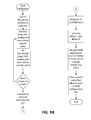
- FIG. 9B gives an example algorithm flowchart to accomplish the calibration for a sensor.
- Branch circuits Modern data centers host a tremendous number of computing devices, such as web servers and the data storage systems necessary for enterprise software operations, cloud computing, Internet access and applications, and numerous other computing functions.
- the power for the physical equipment within the data center is supplied by branch circuits. So, for example, a rack of servers that are used to host a website may be supplied by a single 20 Amp rated branch circuit.
- These branch circuits originate from a power panel where the source of power is received, which may be a 120 volt, 208 volt or other alternating current (AC) supply, and which may be two or three phase.
- the power supplied to the panel is then distributed across some number of discrete branch circuits.
- Conventional panels may include 42 or 72 branch circuits with each circuit also including a breaker.
- FIG. 1 shows one example implementation of a branch circuit monitoring device 10 .
- a branch circuit monitor 10 is a device that enables the monitoring of individual branch circuits 12 of an electrical panel 14 .
- a typical panel contains 42 or 72 branch circuits, although other panel configurations are possible. These circuits are then routed to equipment or equipment racks where individual computers, networking devices, or similar components draw power from one or more circuits.
- the monitoring of the branch circuit current values can be used, for example, to trigger alarms, both locally and remotely, as well as be archived in a database for retrieval and analysis.
- the branch current monitor 10 is configured to measure and log the branch current of a plurality of branches spanning the power panels of the data center.
- One or more current sensors 16 are used to monitor the current of each branch circuit 12 .
- more than one current sensor 16 may be deployed across various sub-branches of a branch circuit 12 .
- the sub-branch currents may later be summed, such as by a management board, to determine a total branch current.
- each of the current sensors 16 connects to a collection device 18 (e.g., a current measurement board or other collection device) located in the power panel 14 .
- the current sensors 16 provide the collection device 18 with a signal indicative of the branch circuit current.
- the collection device 18 uses the signal from the current sensor 16 to produce a voltage (or other signal) indicative of the measured current that can be understood by a panel processor 20 .
- the panel processor 20 receives each voltage signal (or other type of signal), calculates a current, and stores the current measurement along with a timestamp and address in a memory 22 . This information may be later relayed to a server, such as the Data Center BCM Server 24 shown in FIG.
- the server 24 may periodically report measurements to a building management system (BMS) 28 and/or to a user. Users may also alter the configuration of the branch current monitor 10 by accessing the server 24 .
- a user interface 30 such as a display with a graphical user interface (GUI), may be used to report data or other information to a user.
- GUI graphical user interface
- FIG. 2 shows an example implementation of a collection device 40 (in this implementation, a current measurement board although other collection devices are contemplated) that may be used within a branch circuit monitoring system, such as the branch circuit monitor 10 shown in FIG. 1 .
- the collection device may utilize any method form measuring current and provide the current measurement to a panel processor 50 (shown in FIG. 3 ).
- the collection device 40 may include a rectifier/signal conditioning element 42 , an analog-to-digital (A/D) converter 44 , and an output connection 46 . Together these elements may be configured to convert the signal captured by the current sensor 48 , such as a CT, into a signal that is usable by the panel processor 50 .
- A/D analog-to-digital
- the rectifier/signal conditioning element 42 may comprise a resistor coupled to a voltage rectifier to convert the AC resistor voltage to an equivalent direct current (DC) voltage.
- the resistor may be connected to the terminals of the current sensor 38 (e.g., CT).
- CT direct current
- branch circuit current is nonzero, a current will flow through the resistor creating a measurable voltage drop.
- the resistor voltage will likewise be an AC voltage.
- This element may also comprise a signal conditioner configured to prepare the signal for use by the A/D converter 44 .
- the signal may be amplified (or scaled down) to be in an operable range of the A/D converter 44 and may also be filtered to remove excess noise.
- the A/D converter 44 may be configured to accept a DC input and the rectifier may only provide a 0 to 1V output. In this case, it may be beneficial to amplify the output of the rectifier in the signal conditioner 42 to produce an output signal.
- the rectified and conditioned signal is then communicated to the A/D converter 44 which then converts the signals from each current sensor 48 into digital values and produces an output for transmission to the panel processor 50 .
- the A/D converter 44 interfaces with a connection element 46 , such as a standard RJ45 connection or any other suitable electrical connection. In one example, the connection element 46 may also be configured to receive DC power from the panel processor 50 .
- each collection device is connected with or otherwise configured to receive an input from N current sensors 48 (e.g., 1 to 8 current sensors). Depending on the implementation, however, any number of current sensors may be connected with to a collection device.
- each power panel may have a single collection device or a plurality of collection devices depending on the number of branch circuits and the implementation of the collection devices.
- FIG. 3 shows an example implementation of a panel processor 50 coupled to a plurality of individual collection devices 40 , such as the collection device 40 shown in FIG. 2 .
- the panel processor 50 may comprise an input circuit 52 , a processor 54 , a data storage element such as a memory 56 , and a network connection 58 .
- the processor 54 is configured to perform current calculations by executing instructions stored in the memory 56 .
- the memory 56 may also store any needed constant values for current calculations. Once each current calculation is completed, the processor 54 may store the results in the memory 56 along with an address associated with the result, and a timestamp.
- the network connection 58 may then be used to send the current measurement(s), the address(es), and a timestamp(s) to a server 60 at regular intervals, irregular intervals, or based on a command from the server 60 .
- the panel processor 50 may receive configuration data from the user via the server 60 .
- a branch circuit monitoring server 60 is coupled with each panel processor within a data center. Since there may be hundreds of panels in a data center, there may in turn be hundreds of panel processors obtaining and recording data from thousands of branch circuits.
- the server 60 is connected with a database (see, e.g., FIG. 1 ) and is configured to request data from the processors 54 of the panel processors 50 and store the collected data in the database (or other form of data storage). Like the processor 54 , the database may include the branch ID, the current value and the time stamp.
- the memory 56 at the panel processors 50 may be cleared thereby allowing the memory size at the panel processors 50 to be relatively small.
- the collection device may have only sufficient memory to store only the most recent measurements or some number of measurements that would occur between polling cycles of the panel processor to the collection device.
- the server 60 , panel processors 50 and collection devices 40 are arranged in a programmable modular system.
- the system may be deployed in any data center with any number of branch circuits; the system easily adapts to the addition or removal of circuits, and does not require extensive customization for deployment.
- the server 60 and panel processors 50 may be configured for self-discovery of new collection devices, circuits, etc., so that user programming or configuration of the system is minimized or even eliminated.
- a building management system may be configured to receive and display the measured parameters.
- the building management system is connected to the server by way of a Modbus® TCP connection, although other forms of standard or proprietary communications protocols are possible.
- the system also provides the data center or the purchasers of a circuit to manage the circuit usage.
- the data center may utilize the full capacity of a given circuit or set of circuits before installing additional panels and circuits. If, for example, a 20 amp circuit is a supplying at most 10 amps, then there are approximately 8 amps of underutilized capacity on that circuit (considering that it is typical practice to not fully load the circuit in order to avoid tripping the breaker). Across several panels there may additional underutilized capacity. Thus, the circuits may be rearranged or additional equipment coupled with the circuit rather than adding additional panels.
- the BMS module within the BMS system may be further configured to automatically notify the user when such conditions occur.
- the panel processor 50 is connected with and configured to collect data, such as via polling or interrupt, from the collection devices 40 (e.g., a plurality of individual current measurement boards).
- each of the collection devices 40 is connected with the panel processor 50 by way of a twisted pair parallel connection, although other forms of communication and connection are possible, such as I2C, SPI, or USB.
- the panel processor 50 includes an input 52 for receiving the data from the collection devices 40 , a processor 54 , and a storage device, such as some form of memory 56 , where the data is stored at the panel processor 50 .
- the processor 54 stores an indication of the branch where a particular measurement was taken (e.g., a branch ID), the measured current, and a time stamp.
- each collection device is connected with or otherwise configured to receive input from eight current sensors. Depending on the implementation, however, any number of branch circuits may be connected with a collection device. In one implementation, the collection device is configured to poll each branch circuit monitor once per second or at some other interval or in response to a command, and may further be configured to store the measured current with association to the branch circuit where the measurement was taken as well as the time.
- the panel processor 50 receives the measurements from each of the current sensors via the collection devices 40 .
- the panel processor 50 receives one or more DC voltage inputs from each collection device 40 .
- the panel processor 50 is adapted to receive a very large number of signals as the system is expanded to cover more and more branch circuits.
- the panel processor 50 may have one input for every current sensor.
- the panel processor 50 may employ an input circuit 52 comprising multiplexers and logic circuitry as needed.
- additional panel processors 50 may be added once a panel processor 50 has run out of inputs.
- the panel processor 50 may then convert the voltage measurements into current readings constantly, according to a schedule, or according to a user command. Using the example provided above, the panel processor 50 may constantly receive a 0 to 5 VDC signal representing a voltage drop across a resistor. The panel processor 50 may then solve for the branch current by determining the resistor current (using Ohm's law and accounting for any gain produced by the output circuit) and compensating for the turns ratio of the CT.
- the BCM device 100 comprises a panel processor 101 , one or more collection devices 102 (e.g., current measurement or collection circuit boards), and one or more current sensors 103 (e.g., current transformers (CTs)) per collection device.
- the panel processor 101 may comprise any known processor, such as a general purpose processor, a special purpose processor, an ASIC, a digital signal processor (DSP) or the like.
- the panel processor comprises an ARM Cortex-8 processor using a Linux operating system with an easily modifiable programming language to ensure upgrades, patches, and additional features are as simple as upgrading a standard PC computer.
- other processors and operating systems such as an Intel Atom processor using Windows 8 RT can be used.
- the BCM device uses split-core CT current sensors on each circuit to allow for easy installation of “live” panels without the need to de-energize.
- Implementations of the BCM device may also use solid core CTs, or other current sensors such as Hall Effect sensors, or Rogowski coils.
- the panel processor, collection boards, and current sensors are small modular devices that are adapted to be installed inside of the panel enclosure.
- the collection devices connect to the panel process by means of a multi-conductor cable, such as a category 5 (Cat 5) Ethernet cable 104 for a simple parallel transmission of control and sensor signals or ribbon cable for a serial connection of the collection devices in a daisy-chain fashion in an alternate embodiment.
- the current sensors connect to the collection devices by means of a simple twisted pair cable 105 .
- the PoE splitter 107 passes network communications to and from the panel processor Ethernet interface and the rest of the network, and also provides 5V DC power to the panel processor.
- FIGS. 5A and 5B show physical and logical depictions of an example implementation of a collection device and its corresponding current sensors.
- the current sensors comprise current transformer (CT) current sensors 203 and the collection device comprises a current transformer interface (CTIF) board 202 .
- CT current sensors 203 are coupled to each branch circuit and provide a signal indicative of the current flowing through the branch circuit to the CTIF board collection devices 202 .
- CT current sensor 203 may be both physically and inductively coupled to a component in the branch circuit, such as a power cable, a circuit breaker, or any other component that has the full or partial branch current.
- the CT current sensor 203 is also connected directly to the CTIF board collection device 202 , providing the CTIF board collection device 202 with a signal that is indicative of the current flowing through the branch circuit.
- the CT current sensor 203 will produce a scaled AC voltage indicative of 6 to 10 amps (e.g., according to the turns ratio of the CT current sensor to the part the CT current sensor is coupled to).
- the CT current sensors 203 generate an induced current proportional to the actual current passing through a branch circuit conductor that is installed through the air gap core of the CT current sensor 203 .
- the CT current sensors 203 may comprise a split-core or solid core device.
- a split-core CT current sensor 203 allows the CT core to open and enclose the conductor without disconnecting or de-energizing the circuit.
- a solid core CT current sensor 203 may be used on a new installation before the circuits are energized. As shown in FIGS.
- a plurality of CT current sensors 203 connect to a collection device circuit board, also known as the CT interface (CTIF) board collection device 202 .
- CTIF CT interface
- a plurality of CTIF boards collection devices 202 connect to the panel processor 101 (e.g., via Cat 5 cables or other methods) as previously described to give a total circuit capacity (e.g., a total capacity of at least 42 circuits in one implementation).
- One implementation supports six (6) CTIF board collection devices 202 , although other implementations are possible.
- each CTIF board collection device 202 provides a signal termination resistor for each of the connected CT current sensors, converting the induced current that is proportional to the branch circuit current into a voltage by Ohm's Law.
- a digital signal e.g., digital word
- a branch circuit current may be indirectly or directly coupled with a Hall Effect sensor to generate an AC or DC voltage proportional to the current in the conductor (as a function of time), or further converted to a DC signal through a rectifier or other signal conditioning circuit (e.g. integrator).
- a rectifier or other signal conditioning circuit e.g. integrator
- These voltages are then routed to a single RMS-to-DC converter integrated circuit 204 by means of a multiplexer integrated circuit 205 under the control of a panel processor, such as by way of address select lines 207 .
- a multiplexer integrated circuit 205 under the control of a panel processor, such as by way of address select lines 207 .
- an 8:1 multiplexer and thus three (3) address select lines 207 are used, although other configurations are possible.
- Other implementations, for example, could use a 16:1 or 32:1 multiplexer for supporting more CT connections per CTIF 202 .
- a benefit of using the RMS-to-DC converter circuitry 204 for the CT current sensors 203 is that the installation of the CT sensors 203 becomes non-critical since there is no longer a polarity associated with the current value, easing installation.
- the RMS-to-DC converter 204 may be omitted for use with sensors other than CT sensors 203 that product a DC voltage as their output, such as a Hall Effect current sensor.
- the DC voltage produced by the RMS-to-DC converter circuitry 204 (or directly from the multiplexer 205 in the case of a DC current sensor implementation) is transmitted to an operational amplifier circuit 206 provides buffering and a low-impedance output for the CTIF board collection device 202 for transferring the DC voltage signal to the panel processor.
- the operational amplifier circuit 206 could include non-inverting gain to increase the amplitude of the DC voltage.
- the DC voltage output of the operational amplifier 206 is connected to the signal output connector 208 of the CTIF board collection device 202 .
- the output signal radiometrically corresponds to a specific branch circuit current, and the voltage is then sampled by the panel processor via an A/D converter and a periodic interval, nominally once per second (1 Hz), or at a rate supported by the hardware and the customer's needs.
- the panel processor has a built-in A/D converter that is multiplexed by the operating system to appear as individual A/D converter inputs (e.g., seven individual A/D converter inputs).
- Other implementations may employ external A/D converter devices, either multiplexed, or dedicated, per CTIF board collection device 202 , or even per CT sensor 203 .
- the A/D converter, or A/D converters may be part of the CTIF board collection device 202 , or be part of the panel processor.
- the CTIF board collection device 202 has one or more A/D converters that transmit a CT digital word to the panel processor by a digital signal.
- the resulting digital signal value is then stored in a panel processor memory for later processing by software executing on the panel processor.
- the panel processor cycles through all the CTIF board collection devices 202 and attached CT sensors 203 connected to the CTIF board collection devices 202 to represent all the digital branch circuit current values and stores the digital branch circuit current values in the panel processor memory.
- FIG. 6 shows an example implementation of a system monitoring a branch circuit 300 .
- a collection of digital values representing the branch circuit currents are interpreted by software executing on a panel processor as a current value, measured in Amperes RMS.
- the panel processor executes two interdependent programs that retrieve, process, and communicate the branch circuit current values to the end user, or to another computer by means of a communications medium and protocol.
- the programs are written in server-side JavaScript, known as node.js. Other programming languages such as, but not limited to, C, C++, or Python are possible in alternate implementations. As shown in FIG.
- the first program called the CT collection server (ctcServer) 301 , interfaces with the panel processor digital input and output (I/O) signals 303 A and A/D converter inputs 303 B to set the digital bits of the address lines connected to the collection device's (e.g., a CTIF board collection device's) multiplexers, and sample the voltage output of the collection devices, respectively.
- the ctcServer program uses control structures to sequence and sample the DC voltage outputs presented by the collection devices, and store the converted digital value in a distinct memory location 304 for each value.
- the second program Upon completion of the collection, conversion, and storage of all the DC voltage values representing all the branch circuit currents, then collates and transmits the digital values to the second program via a network socket protocol 305 , although any type of communication such as a generic communication channel between a physical and/or logical layer may be used.
- the second program called the branch circuit monitor server (bcmServer) 306 , receives the values from the ctcServer 301 , stores them in distinct memory locations 304 , and computes short-term statistics 307 on the values for each circuit such as maximum, minimum, and average values, in addition to the current real-time value of the branch circuit current. It also provides for configuration of the panel processor via privileged access.
- the first and second programs execute on the same panel processor. In an alternate implementation, the two programs execute on separate processors connected by a networking media and protocol, or by other physical and/or logical means.
- the bcmServer 306 also instantiates and executes an embedded hypertext transfer protocol (HTTP) server 308 to provide one or more networked users 309 with one of several visualizations of the branch circuit current data 310 .
- HTTP hypertext transfer protocol
- the HTTP server of the bcmServer 306 can communicate with any number and type of HTTP clients such as, but not limited to, Internet Explorer, Firefox, or Google Chrome.
- the bcmServer 306 supports alarm threshold that activate if a branch circuit current exceed a set value, or values, on an instantaneous, or time-averaged basis. The bcmServer 306 will forward such alarm conditions to a central computer, or may display them on the embedded web server, or both.
- the bcmServer 306 web server allows privileged users to configure elements of the BCM such as client/customer name associated with a circuit, change circuit breaker amperage ratings, set, modify, and clear alarms, and perform built-in tests (BIT).
- the bcmServer 306 utilizes a configuration file 311 , such as in a JavaScript Object Notation (JSON) format, to store the parameters of each branch circuit such as customer name, circuit number, breaker capacity, CT number, etc.
- JSON JavaScript Object Notation
- the configuration file can be modified through the privileged access or offline and uploaded to the panel processor.
- Alternate formats for the configuration file such as, but not limited to, extensible markup language (XML) or comma separated values (CSV) are possible in alternative embodiments.
- the BCM devices' one or more panel processor 400 communicate to a central computer 401 executing software called the data center server (dcServer) 402 .
- the central computer 401 , dcServer program 402 , and two or more BCM devices comprise a BCM System (BCMS).
- the BCMS allows centralized access, data storage, querying, retrieval, and visualization of all the circuits in the data center.
- the BCMS can communicate with third-party data center information management (DCIM) or building management system (BMS) software 403 via standard or proprietary protocols as desired by the customer.
- DCIM third-party data center information management
- BMS building management system
- the central computer 401 and dcServer software 402 may send alarm, status, or diagnostic messages to networked users by means SMS texts, email, or voice communications.
- the central computer 401 hosts a database management system (DBMS) 404 that stores and retrieves historical branch circuit current data.
- DBMS 404 allows short-, medium-, and long-range data storage for each branch circuit.
- the panel processors 101 will send a running-average value of each branch circuit at a rate of once per minute ( 1/60 Hz) to the central computer that stores each branch circuit value in the DBMS 404 .
- the DBMS 404 will store these values in a circular buffer such that the last 24 hours of 1/60 Hz data for each branch circuit current is available for viewing or analysis.
- the DBMS 404 will calculate and store running averages for the branch circuit currents at rates of once per quarter hour, hour, six hours, and daily in a similar circular buffer of length commensurate with the sampling rate. Users can query, view, and analyze branch circuit current data in graphical format to look for trends or trouble conditions over a plurality of time and date ranges.
- a BCMS supports branch circuit current monitoring of DC currents.
- the current sensors comprise non-contact current sensors 501 , such as using Hall Effect sensor devices 502 to produce a DC voltage that is proportional to the DC or AC current flowing through a branch circuit conductor.
- the collection devices will bypass or omit the RMS-to-DC converter circuitry 504 and directly connect the Hall Effect sensor voltage through a multiplexer 505 to an operational amplifier circuit 506 .
- the branch circuit conductor is arranged parallel to the major plane of the Hall Effect sensor and the current is inferred by means of the Hall Effect.
- the branch circuit current induces a magnetic flux 508 in a permeable core 509 similar to that of a conventional CT, with the Hall Effect sensor's main plane perpendicular to the flux flow.
- the software would be minimally changed to reflect a DC current versus an AC current.
- a variation of the aforementioned Hall Effect sensors outputs a digital signal, such as a pulse width modulation (PWM) waveform.
- PWM pulse width modulation
- This method provides increased accuracy and immunity to noise as compared to an analog output.
- the panel processor starts a counter when the waveform transitions from low to high logic levels, and stops the counter when the waveform transitions from high to low logic levels.
- the counter value is compared to a value of the counter for a high to high logic level interval, indicating a radiometric representation of the current value.
- one or more voltage sensors may be connected.
- a voltage sensor connects between a phase voltage line and the neutral line of a polyphase system, typically two or three phases.
- the voltage sensor translates the line-to-neutral voltage down from a high voltage, typically 120V RMS to a lower voltage, typically less than 5V RMS.
- the voltage sensor output then connects to the collection device in a similar fashion as a current sensor.
- the voltage is applied across the sensing resistor in the same manner as the current sensor, and multiplexed and converted to a DC voltage via the RMS-to-DC converter integrated circuit, or a rectification circuit.
- the DC voltage is either transmitted to the panel processor and converted to a digital value by means of the panel processor A/D converter, or directly converted by means of an A/D converter resident on the collection device, and transmitted to the panel processor as a digital signal to a digital input port on the panel processor.
- the resulting digital values of the phase voltages are interpreted by the software on the panel processor to represent Volts RMS.
- the phase voltages are associated to one or more branch circuits by a defined pattern.
- a current sensor can determine the branch circuit current measured in Amperes RMS, and the phase voltage is determined by a voltage sensor voltage measured in Volts RMS. From these two values, the apparent power can be accurately calculated measured in Volt-Amps (VA).
- VA Volt-Amps
- the apparent power describes the accurate power drawn by the branch circuit.
- energy usage by the branch circuit can be calculated by integrating apparent power over a time interval. The resulting energy value is measured in Volt-Amp-hours (VA-h). This energy value can be used in subsequent calculations to estimate cooling requirements of a data center based on energy usage of equipment connected to branch circuits.
- FIG. 9A depicts an example calibration setup.
- the method to calibrate one or more sensors involves using a goal-seek algorithm and a test setup to provide a known value of current through the representative conductor that the sensor will be associated with by means of a calibration station.
- the response parameters of the DC sensor are an offset value and a full-scale reading value, both defined in Amperes. These two values are unique to each sensor and stored in the JSON configuration file 311 as described above.
- FIG. 9B gives an algorithm flowchart to accomplish the calibration for a sensor. The algorithm may be extended to allow calibration of any number of sensors that are connected to the calibration station.
- the new offset and full-scale values for each sensor are stored it the configuration file for use in an operational system. If a sensor is replaced, or the conductor that it is measuring is changed, the calibration needs to be repeated with the new sensor and/or the new conductor.
- joinder references do not necessarily infer that two elements are directly connected and in fixed relation to each other. It is intended that all matter contained in the above description or shown in the accompanying drawings shall be interpreted as illustrative only and not limiting. Changes in detail or structure may be made without departing from the spirit of the invention as defined in the appended claims.
Abstract
Description
Claims (20)
Priority Applications (4)
| Application Number | Priority Date | Filing Date | Title |
|---|---|---|---|
| US13/963,844 US8610438B1 (en) | 2012-08-09 | 2013-08-09 | Branch circuit monitor |
| US14/108,134 US8988062B2 (en) | 2012-08-09 | 2013-12-16 | Branch circuit monitor |
| US14/666,304 US20150260761A1 (en) | 2012-08-09 | 2015-03-23 | Branch Circuit Monitor |
| US14/666,283 US20150260767A1 (en) | 2012-08-09 | 2015-03-23 | Branch Circuit Monitor |
Applications Claiming Priority (3)
| Application Number | Priority Date | Filing Date | Title |
|---|---|---|---|
| US201261681406P | 2012-08-09 | 2012-08-09 | |
| US201261681527P | 2012-08-09 | 2012-08-09 | |
| US13/963,844 US8610438B1 (en) | 2012-08-09 | 2013-08-09 | Branch circuit monitor |
Related Child Applications (1)
| Application Number | Title | Priority Date | Filing Date |
|---|---|---|---|
| US14/108,134 Continuation US8988062B2 (en) | 2012-08-09 | 2013-12-16 | Branch circuit monitor |
Publications (1)
| Publication Number | Publication Date |
|---|---|
| US8610438B1 true US8610438B1 (en) | 2013-12-17 |
Family
ID=49725748
Family Applications (4)
| Application Number | Title | Priority Date | Filing Date |
|---|---|---|---|
| US13/963,844 Expired - Fee Related US8610438B1 (en) | 2012-08-09 | 2013-08-09 | Branch circuit monitor |
| US14/108,134 Expired - Fee Related US8988062B2 (en) | 2012-08-09 | 2013-12-16 | Branch circuit monitor |
| US14/666,304 Abandoned US20150260761A1 (en) | 2012-08-09 | 2015-03-23 | Branch Circuit Monitor |
| US14/666,283 Abandoned US20150260767A1 (en) | 2012-08-09 | 2015-03-23 | Branch Circuit Monitor |
Family Applications After (3)
| Application Number | Title | Priority Date | Filing Date |
|---|---|---|---|
| US14/108,134 Expired - Fee Related US8988062B2 (en) | 2012-08-09 | 2013-12-16 | Branch circuit monitor |
| US14/666,304 Abandoned US20150260761A1 (en) | 2012-08-09 | 2015-03-23 | Branch Circuit Monitor |
| US14/666,283 Abandoned US20150260767A1 (en) | 2012-08-09 | 2015-03-23 | Branch Circuit Monitor |
Country Status (1)
| Country | Link |
|---|---|
| US (4) | US8610438B1 (en) |
Cited By (17)
| Publication number | Priority date | Publication date | Assignee | Title |
|---|---|---|---|---|
| US20120217954A1 (en) * | 2011-02-25 | 2012-08-30 | Veris Industries, Llc | Current meter with voltage awareness |
| US20160069933A1 (en) * | 2012-12-31 | 2016-03-10 | Veris Industries, Llc | Power meter with automatic configuration |
| US20170184638A1 (en) * | 2015-12-28 | 2017-06-29 | Veris Industries, Llc | Branch current monitor with reconfiguration |
| US20170185237A1 (en) * | 2015-12-28 | 2017-06-29 | Veris Industries, Llc | Branch current monitor with client level access |
| US9912192B2 (en) | 2015-06-22 | 2018-03-06 | Iron Mountain Incorporated | Power distribution visibility in data center environments |
| US10267833B2 (en) | 2016-11-02 | 2019-04-23 | Equinix, Inc. | Power monitoring probe for monitoring power distribution in an electrical system |
| US10274572B2 (en) | 2015-12-28 | 2019-04-30 | Veris Industries, Llc | Calibration system for a power meter |
| US10289184B2 (en) | 2008-03-07 | 2019-05-14 | Sunbird Software, Inc. | Methods of achieving cognizant power management |
| US10371721B2 (en) | 2015-12-28 | 2019-08-06 | Veris Industries, Llc | Configuration system for a power meter |
| US10408911B2 (en) | 2015-12-28 | 2019-09-10 | Veris Industries, Llc | Network configurable system for a power meter |
| US10705126B2 (en) | 2017-05-19 | 2020-07-07 | Veris Industries, Llc | Energy metering with temperature monitoring |
| JP2020122805A (en) * | 2020-05-22 | 2020-08-13 | 日置電機株式会社 | Addition average unit and measuring device |
| US11193958B2 (en) | 2017-03-03 | 2021-12-07 | Veris Industries, Llc | Non-contact voltage sensor |
| US11215650B2 (en) | 2017-02-28 | 2022-01-04 | Veris Industries, Llc | Phase aligned branch energy meter |
| EP3900143A4 (en) * | 2018-12-17 | 2022-09-07 | Xslent Energy Technologies, LLC | Sensor-based energy management enclosure and distributed energy resource management based on sensor data |
| US20230417814A1 (en) * | 2022-06-28 | 2023-12-28 | Sagemcom Energy & Telecom Sas | Detection of loss of neutral or phase |
| US11914004B2 (en) | 2020-05-28 | 2024-02-27 | Anord Mardix (USA) Inc. | Current transformer with embedded voltage field detection and thermal sensing |
Families Citing this family (4)
| Publication number | Priority date | Publication date | Assignee | Title |
|---|---|---|---|---|
| US10211673B2 (en) | 2015-03-04 | 2019-02-19 | Siemens Industry, Inc. | Apparatus and methods for timestamping electrical data in a panel meter |
| WO2019090324A1 (en) * | 2017-11-06 | 2019-05-09 | Ramsey Winch Company | Electric winch control module with magnetic flux shield |
| CN109728936B (en) * | 2018-12-05 | 2021-10-29 | 北京电力自动化设备有限公司 | Communication management method, device and system for high-voltage chain type static var generator |
| US20210151876A1 (en) * | 2019-11-15 | 2021-05-20 | Anokiwave, Inc. | Integrated circuit and system with tracking |
Citations (16)
| Publication number | Priority date | Publication date | Assignee | Title |
|---|---|---|---|---|
| US5181026A (en) * | 1990-01-12 | 1993-01-19 | Granville Group, Inc., The | Power transmission line monitoring system |
| US6330516B1 (en) | 2000-03-27 | 2001-12-11 | Power Distribution, Inc. | Branch circuit monitor |
| US20050180069A1 (en) * | 2004-02-17 | 2005-08-18 | Serguei Tchernobrivets | Ground-fault monitor for multiple circuits |
| US20050212526A1 (en) * | 2004-03-23 | 2005-09-29 | Blades Frederick K | Electrical wiring inspection system |
| US7230414B2 (en) | 2004-10-21 | 2007-06-12 | Veris Industries, Llc | Current sensor that includes a pair of segments |
| US20070146944A1 (en) * | 2005-12-27 | 2007-06-28 | General Protecht Group, Inc. | Apparatus and methods for testing the life of a leakage current protection device |
| US7453267B2 (en) * | 2005-01-14 | 2008-11-18 | Power Measurement Ltd. | Branch circuit monitor system |
| US20100145641A1 (en) * | 2008-12-09 | 2010-06-10 | Consolidated Edison Company Of New York, Inc. | System for monitoring and assessing electrical circuits and method of operation |
| US20100176960A1 (en) * | 2008-11-21 | 2010-07-15 | Michael Bitsch | Branch current monitor with an alarm |
| US20100235122A1 (en) | 2009-03-13 | 2010-09-16 | Mccrea Benjamin J | Branch circuit monitor power measurement |
| US20100308792A1 (en) * | 2009-06-04 | 2010-12-09 | Matthew Rupert | Branch current monitor with configuration |
| US20110291488A1 (en) * | 2010-05-28 | 2011-12-01 | Namwook Paik | System for self-powered, wireless monitoring of electrical current, power and energy |
| US20120049879A1 (en) * | 2010-08-24 | 2012-03-01 | Crites David E | Active and passive monitoring system for installed photovoltaic strings, substrings, and modules |
| US20120278562A1 (en) * | 2011-04-27 | 2012-11-01 | Veris Industries, Llc | Branch circuit monitor with paging register |
| US20120327563A1 (en) * | 2011-06-21 | 2012-12-27 | Darcy Cook | Load Center with Branch-Level Current Sensors Integrated into Power Buses on a Unit with On-Board Circuit Breaker Mounts |
| US8421443B2 (en) | 2008-11-21 | 2013-04-16 | Veris Industries, Llc | Branch current monitor with calibration |
Family Cites Families (14)
| Publication number | Priority date | Publication date | Assignee | Title |
|---|---|---|---|---|
| AT368814B (en) * | 1979-10-05 | 1982-11-10 | Vmw Ranshofen Berndorf Ag | DEVICE FOR MEASURING THE CURRENT STRENGTH IN TRACK RAILS, ESPECIALLY ELECTROLYSIS FOR REFINING COPPER |
| US4709339A (en) * | 1983-04-13 | 1987-11-24 | Fernandes Roosevelt A | Electrical power line parameter measurement apparatus and systems, including compact, line-mounted modules |
| US4645908A (en) * | 1984-07-27 | 1987-02-24 | Uhr Corporation | Residential heating, cooling and energy management system |
| CA1330234C (en) * | 1989-09-29 | 1994-06-14 | Timothy M. Wilkerson | Overcurrent protection relay with communications |
| US5428495A (en) * | 1992-09-30 | 1995-06-27 | Eaton Corporation | Electrical switching apparatus with digital trip unit and automatic frequency selection |
| US5426360A (en) * | 1994-02-17 | 1995-06-20 | Niagara Mohawk Power Corporation | Secondary electrical power line parameter monitoring apparatus and system |
| US5861683A (en) * | 1997-05-30 | 1999-01-19 | Eaton Corporation | Panelboard for controlling and monitoring power or energy |
| US6728646B2 (en) * | 1998-02-23 | 2004-04-27 | Enerwise Global Technologies, Inc. | Energy information system and sub-measurement board for use therewith |
| US7230316B2 (en) * | 2002-12-27 | 2007-06-12 | Semiconductor Energy Laboratory Co., Ltd. | Semiconductor device having transferred integrated circuit |
| JP5248269B2 (en) * | 2008-10-31 | 2013-07-31 | 株式会社東芝 | Circuit breaker switching control device and circuit breaker switching control system |
| US8103466B2 (en) * | 2009-01-14 | 2012-01-24 | Accenture Global Services Limited | Distribution system analysis using meter data |
| US8554388B2 (en) * | 2009-11-06 | 2013-10-08 | Jeffrey Kibbie | Power intervening and management panel, system and method for a power control panel |
| US8519843B2 (en) * | 2011-01-27 | 2013-08-27 | International Business Machines Corporation | Power distribution device communications platform |
| US20130271895A1 (en) * | 2012-04-12 | 2013-10-17 | Hampden Kuhns | User installable branch circuit meter |
-
2013
- 2013-08-09 US US13/963,844 patent/US8610438B1/en not_active Expired - Fee Related
- 2013-12-16 US US14/108,134 patent/US8988062B2/en not_active Expired - Fee Related
-
2015
- 2015-03-23 US US14/666,304 patent/US20150260761A1/en not_active Abandoned
- 2015-03-23 US US14/666,283 patent/US20150260767A1/en not_active Abandoned
Patent Citations (17)
| Publication number | Priority date | Publication date | Assignee | Title |
|---|---|---|---|---|
| US5181026A (en) * | 1990-01-12 | 1993-01-19 | Granville Group, Inc., The | Power transmission line monitoring system |
| US6330516B1 (en) | 2000-03-27 | 2001-12-11 | Power Distribution, Inc. | Branch circuit monitor |
| US20050180069A1 (en) * | 2004-02-17 | 2005-08-18 | Serguei Tchernobrivets | Ground-fault monitor for multiple circuits |
| US20050212526A1 (en) * | 2004-03-23 | 2005-09-29 | Blades Frederick K | Electrical wiring inspection system |
| US7230414B2 (en) | 2004-10-21 | 2007-06-12 | Veris Industries, Llc | Current sensor that includes a pair of segments |
| US7453267B2 (en) * | 2005-01-14 | 2008-11-18 | Power Measurement Ltd. | Branch circuit monitor system |
| US20070146944A1 (en) * | 2005-12-27 | 2007-06-28 | General Protecht Group, Inc. | Apparatus and methods for testing the life of a leakage current protection device |
| US20100176960A1 (en) * | 2008-11-21 | 2010-07-15 | Michael Bitsch | Branch current monitor with an alarm |
| US8421639B2 (en) | 2008-11-21 | 2013-04-16 | Veris Industries, Llc | Branch current monitor with an alarm |
| US8421443B2 (en) | 2008-11-21 | 2013-04-16 | Veris Industries, Llc | Branch current monitor with calibration |
| US20100145641A1 (en) * | 2008-12-09 | 2010-06-10 | Consolidated Edison Company Of New York, Inc. | System for monitoring and assessing electrical circuits and method of operation |
| US20100235122A1 (en) | 2009-03-13 | 2010-09-16 | Mccrea Benjamin J | Branch circuit monitor power measurement |
| US20100308792A1 (en) * | 2009-06-04 | 2010-12-09 | Matthew Rupert | Branch current monitor with configuration |
| US20110291488A1 (en) * | 2010-05-28 | 2011-12-01 | Namwook Paik | System for self-powered, wireless monitoring of electrical current, power and energy |
| US20120049879A1 (en) * | 2010-08-24 | 2012-03-01 | Crites David E | Active and passive monitoring system for installed photovoltaic strings, substrings, and modules |
| US20120278562A1 (en) * | 2011-04-27 | 2012-11-01 | Veris Industries, Llc | Branch circuit monitor with paging register |
| US20120327563A1 (en) * | 2011-06-21 | 2012-12-27 | Darcy Cook | Load Center with Branch-Level Current Sensors Integrated into Power Buses on a Unit with On-Board Circuit Breaker Mounts |
Cited By (23)
| Publication number | Priority date | Publication date | Assignee | Title |
|---|---|---|---|---|
| US10289184B2 (en) | 2008-03-07 | 2019-05-14 | Sunbird Software, Inc. | Methods of achieving cognizant power management |
| US10006948B2 (en) * | 2011-02-25 | 2018-06-26 | Veris Industries, Llc | Current meter with voltage awareness |
| US20120217954A1 (en) * | 2011-02-25 | 2012-08-30 | Veris Industries, Llc | Current meter with voltage awareness |
| US20160069933A1 (en) * | 2012-12-31 | 2016-03-10 | Veris Industries, Llc | Power meter with automatic configuration |
| US9689899B2 (en) * | 2012-12-31 | 2017-06-27 | Veris Industries, Llc | Power meter with automatic configuration |
| US9912192B2 (en) | 2015-06-22 | 2018-03-06 | Iron Mountain Incorporated | Power distribution visibility in data center environments |
| US9778290B2 (en) * | 2015-12-28 | 2017-10-03 | Veris Industries, Llc | Branch current monitor with reconfiguration |
| US10274572B2 (en) | 2015-12-28 | 2019-04-30 | Veris Industries, Llc | Calibration system for a power meter |
| US20170184638A1 (en) * | 2015-12-28 | 2017-06-29 | Veris Industries, Llc | Branch current monitor with reconfiguration |
| US10371721B2 (en) | 2015-12-28 | 2019-08-06 | Veris Industries, Llc | Configuration system for a power meter |
| US10371730B2 (en) * | 2015-12-28 | 2019-08-06 | Veris Industries, Llc | Branch current monitor with client level access |
| US10408911B2 (en) | 2015-12-28 | 2019-09-10 | Veris Industries, Llc | Network configurable system for a power meter |
| US20170185237A1 (en) * | 2015-12-28 | 2017-06-29 | Veris Industries, Llc | Branch current monitor with client level access |
| US10267833B2 (en) | 2016-11-02 | 2019-04-23 | Equinix, Inc. | Power monitoring probe for monitoring power distribution in an electrical system |
| US11215650B2 (en) | 2017-02-28 | 2022-01-04 | Veris Industries, Llc | Phase aligned branch energy meter |
| US11193958B2 (en) | 2017-03-03 | 2021-12-07 | Veris Industries, Llc | Non-contact voltage sensor |
| US10705126B2 (en) | 2017-05-19 | 2020-07-07 | Veris Industries, Llc | Energy metering with temperature monitoring |
| US11085955B2 (en) | 2017-05-19 | 2021-08-10 | Veris Industries, Llc | Energy metering system with temperature monitoring based on circuit breakers of power panel likely to trip |
| EP3900143A4 (en) * | 2018-12-17 | 2022-09-07 | Xslent Energy Technologies, LLC | Sensor-based energy management enclosure and distributed energy resource management based on sensor data |
| JP2020122805A (en) * | 2020-05-22 | 2020-08-13 | 日置電機株式会社 | Addition average unit and measuring device |
| US11914004B2 (en) | 2020-05-28 | 2024-02-27 | Anord Mardix (USA) Inc. | Current transformer with embedded voltage field detection and thermal sensing |
| US20230417814A1 (en) * | 2022-06-28 | 2023-12-28 | Sagemcom Energy & Telecom Sas | Detection of loss of neutral or phase |
| US11921147B2 (en) * | 2022-06-28 | 2024-03-05 | Sagemcom Energy & Telecom Sas | Detection of loss of neutral or phase |
Also Published As
| Publication number | Publication date |
|---|---|
| US8988062B2 (en) | 2015-03-24 |
| US20140368190A1 (en) | 2014-12-18 |
| US20150260761A1 (en) | 2015-09-17 |
| US20150260767A1 (en) | 2015-09-17 |
Similar Documents
| Publication | Publication Date | Title |
|---|---|---|
| US8988062B2 (en) | Branch circuit monitor | |
| CN104301210B (en) | Analysis gateway for measuring device | |
| US9506952B2 (en) | Power meter with automatic configuration | |
| US7493221B2 (en) | System for power sub-metering | |
| US20150212126A1 (en) | System and method for unified power quality monitoring and data collection in a power system having heterogeneous devices for monitoring power quality | |
| US8964360B2 (en) | System to connect and multiplex sensor signals | |
| WO2013111760A1 (en) | Power usage analysis system | |
| US10371721B2 (en) | Configuration system for a power meter | |
| US9804211B2 (en) | Indicators for a power meter | |
| CN109839556A (en) | Use the electric signal measurement equipment of reference signal | |
| WO2018038000A1 (en) | State change detection apparatus, method, and program | |
| WO2021176459A1 (en) | A system and method of energy disaggregation using nonintrusive load monitoring | |
| EP2798358B1 (en) | System and method to measure neutral-to-ground voltage | |
| US20200278384A1 (en) | Monitoring an energy parameter in a distribution station | |
| KR20130096818A (en) | Fixed type mesuring device having split coil | |
| US9329996B2 (en) | Branch circuit monitor with paging register | |
| KR20110015358A (en) | Electric power measuring system for multi-line increasing efficiency and simplicity thereof | |
| Khandait et al. | Real time monitoring of transformer using IOT | |
| CA2823375A1 (en) | Branch circuit monitor | |
| US20230314491A1 (en) | Energy Meters and Energy Monitoring Systems and Methods | |
| KR101006069B1 (en) | Portable power system dynamic monitoring equipment | |
| CA3026918C (en) | Energy metering for a building | |
| US11860202B2 (en) | Devices, systems and methods for meter setup verification | |
| US10371730B2 (en) | Branch current monitor with client level access | |
| KR20200024483A (en) | Power measuring system |
Legal Events
| Date | Code | Title | Description |
|---|---|---|---|
| STCF | Information on status: patent grant |
Free format text: PATENTED CASE |
|
| AS | Assignment |
Owner name: PRECISION AIR AND ENERGY, LLC, COLORADO Free format text: ASSIGNMENT OF ASSIGNORS INTEREST;ASSIGNORS:SYKORA, MONTGOMERY J;JANOVY, DANIEL L;JANOVY, DAVID L;REEL/FRAME:033643/0920 Effective date: 20120905 |
|
| AS | Assignment |
Owner name: PRECISION AIR AND ENERGY, LLC, COLORADO Free format text: ASSIGNMENT OF ASSIGNORS INTEREST;ASSIGNORS:SYKORA, MONTGOMERY J;JANOVY, DANIEL L;JANOVY, DAVID L;REEL/FRAME:033643/0927 Effective date: 20120905 |
|
| AS | Assignment |
Owner name: PRECISION AIR & ENERGY SERVICES, LLC, COLORADO Free format text: CORRECTIVE ASSIGNMENT TO CORRECT THE NAME OF THE ASSIGNEE PREVIOUSLY RECORDED ON REEL 033643 FRAME 0927. ASSIGNOR(S) HEREBY CONFIRMS THE NAME OF THE ASSIGNEE;ASSIGNORS:SYKORA, MONTGOMERY J;JANOVY, DANIEL L;JANOVY, DAVID L;REEL/FRAME:033685/0240 Effective date: 20120905 |
|
| REMI | Maintenance fee reminder mailed | ||
| FEPP | Fee payment procedure |
Free format text: SURCHARGE FOR LATE PAYMENT, SMALL ENTITY (ORIGINAL EVENT CODE: M2554) |
|
| MAFP | Maintenance fee payment |
Free format text: PAYMENT OF MAINTENANCE FEE, 4TH YR, SMALL ENTITY (ORIGINAL EVENT CODE: M2551) Year of fee payment: 4 |
|
| FEPP | Fee payment procedure |
Free format text: MAINTENANCE FEE REMINDER MAILED (ORIGINAL EVENT CODE: REM.); ENTITY STATUS OF PATENT OWNER: SMALL ENTITY |
|
| LAPS | Lapse for failure to pay maintenance fees |
Free format text: PATENT EXPIRED FOR FAILURE TO PAY MAINTENANCE FEES (ORIGINAL EVENT CODE: EXP.); ENTITY STATUS OF PATENT OWNER: SMALL ENTITY |
|
| STCH | Information on status: patent discontinuation |
Free format text: PATENT EXPIRED DUE TO NONPAYMENT OF MAINTENANCE FEES UNDER 37 CFR 1.362 |
|
| FP | Lapsed due to failure to pay maintenance fee |
Effective date: 20211217 |