JP2012505806A - Lifting vehicle - Google Patents
Lifting vehicle Download PDFInfo
- Publication number
- JP2012505806A JP2012505806A JP2011531575A JP2011531575A JP2012505806A JP 2012505806 A JP2012505806 A JP 2012505806A JP 2011531575 A JP2011531575 A JP 2011531575A JP 2011531575 A JP2011531575 A JP 2011531575A JP 2012505806 A JP2012505806 A JP 2012505806A
- Authority
- JP
- Japan
- Prior art keywords
- vehicle
- rack
- vehicle according
- shaft
- gripping
- Prior art date
- Legal status (The legal status is an assumption and is not a legal conclusion. Google has not performed a legal analysis and makes no representation as to the accuracy of the status listed.)
- Granted
Links
Images


Classifications
-
- B—PERFORMING OPERATIONS; TRANSPORTING
- B66—HOISTING; LIFTING; HAULING
- B66F—HOISTING, LIFTING, HAULING OR PUSHING, NOT OTHERWISE PROVIDED FOR, e.g. DEVICES WHICH APPLY A LIFTING OR PUSHING FORCE DIRECTLY TO THE SURFACE OF A LOAD
- B66F9/00—Devices for lifting or lowering bulky or heavy goods for loading or unloading purposes
- B66F9/06—Devices for lifting or lowering bulky or heavy goods for loading or unloading purposes movable, with their loads, on wheels or the like, e.g. fork-lift trucks
- B66F9/065—Devices for lifting or lowering bulky or heavy goods for loading or unloading purposes movable, with their loads, on wheels or the like, e.g. fork-lift trucks non-masted
- B66F9/0655—Devices for lifting or lowering bulky or heavy goods for loading or unloading purposes movable, with their loads, on wheels or the like, e.g. fork-lift trucks non-masted with a telescopic boom
-
- B—PERFORMING OPERATIONS; TRANSPORTING
- B66—HOISTING; LIFTING; HAULING
- B66C—CRANES; LOAD-ENGAGING ELEMENTS OR DEVICES FOR CRANES, CAPSTANS, WINCHES, OR TACKLES
- B66C23/00—Cranes comprising essentially a beam, boom, or triangular structure acting as a cantilever and mounted for translatory of swinging movements in vertical or horizontal planes or a combination of such movements, e.g. jib-cranes, derricks, tower cranes
- B66C23/62—Constructional features or details
- B66C23/72—Counterweights or supports for balancing lifting couples
-
- B—PERFORMING OPERATIONS; TRANSPORTING
- B66—HOISTING; LIFTING; HAULING
- B66F—HOISTING, LIFTING, HAULING OR PUSHING, NOT OTHERWISE PROVIDED FOR, e.g. DEVICES WHICH APPLY A LIFTING OR PUSHING FORCE DIRECTLY TO THE SURFACE OF A LOAD
- B66F9/00—Devices for lifting or lowering bulky or heavy goods for loading or unloading purposes
- B66F9/06—Devices for lifting or lowering bulky or heavy goods for loading or unloading purposes movable, with their loads, on wheels or the like, e.g. fork-lift trucks
- B66F9/075—Constructional features or details
- B66F9/08—Masts; Guides; Chains
- B66F9/082—Masts; Guides; Chains inclinable
-
- B—PERFORMING OPERATIONS; TRANSPORTING
- B66—HOISTING; LIFTING; HAULING
- B66F—HOISTING, LIFTING, HAULING OR PUSHING, NOT OTHERWISE PROVIDED FOR, e.g. DEVICES WHICH APPLY A LIFTING OR PUSHING FORCE DIRECTLY TO THE SURFACE OF A LOAD
- B66F9/00—Devices for lifting or lowering bulky or heavy goods for loading or unloading purposes
- B66F9/06—Devices for lifting or lowering bulky or heavy goods for loading or unloading purposes movable, with their loads, on wheels or the like, e.g. fork-lift trucks
- B66F9/075—Constructional features or details
- B66F9/12—Platforms; Forks; Other load supporting or gripping members
- B66F9/125—Platforms; Forks; Other load supporting or gripping members rotatable about a longitudinal axis
-
- B—PERFORMING OPERATIONS; TRANSPORTING
- B66—HOISTING; LIFTING; HAULING
- B66F—HOISTING, LIFTING, HAULING OR PUSHING, NOT OTHERWISE PROVIDED FOR, e.g. DEVICES WHICH APPLY A LIFTING OR PUSHING FORCE DIRECTLY TO THE SURFACE OF A LOAD
- B66F9/00—Devices for lifting or lowering bulky or heavy goods for loading or unloading purposes
- B66F9/06—Devices for lifting or lowering bulky or heavy goods for loading or unloading purposes movable, with their loads, on wheels or the like, e.g. fork-lift trucks
- B66F9/075—Constructional features or details
- B66F9/12—Platforms; Forks; Other load supporting or gripping members
- B66F9/18—Load gripping or retaining means
- B66F9/181—Load gripping or retaining means by suction means
-
- B—PERFORMING OPERATIONS; TRANSPORTING
- B66—HOISTING; LIFTING; HAULING
- B66F—HOISTING, LIFTING, HAULING OR PUSHING, NOT OTHERWISE PROVIDED FOR, e.g. DEVICES WHICH APPLY A LIFTING OR PUSHING FORCE DIRECTLY TO THE SURFACE OF A LOAD
- B66F9/00—Devices for lifting or lowering bulky or heavy goods for loading or unloading purposes
- B66F9/06—Devices for lifting or lowering bulky or heavy goods for loading or unloading purposes movable, with their loads, on wheels or the like, e.g. fork-lift trucks
- B66F9/075—Constructional features or details
- B66F9/12—Platforms; Forks; Other load supporting or gripping members
- B66F9/18—Load gripping or retaining means
- B66F9/182—Load gripping or retaining means by magnetic means
Landscapes
- Engineering & Computer Science (AREA)
- Transportation (AREA)
- Structural Engineering (AREA)
- Mechanical Engineering (AREA)
- Civil Engineering (AREA)
- Life Sciences & Earth Sciences (AREA)
- Geology (AREA)
- Forklifts And Lifting Vehicles (AREA)
- Conveying And Assembling Of Building Elements In Situ (AREA)
- Load-Engaging Elements For Cranes (AREA)
- Handcart (AREA)
- Jib Cranes (AREA)
Abstract
【課題】 可動支持要素(3)、及びその上に取付けられた塔構造(4)を備えたシャシー(2)を含む吊上げ車両(1)を提供する。
【解決手段】 この車両(1)において、前記塔(4)は、旋回可能かつ伸縮自在の張り出し棒(5)、及び材料運搬ラック(6)を備えており、この材料運搬ラック(6)がラック(6)から延びる材料把持手段(7)を備えており、さらにラック(6)が角度的に調整可能な手段(9,10,11,13)により張り出し棒(5)に連結され、前記可動支持要素(3)がシャフト(12,12a,12b)により回転され、それらの少なくとも一つが駆動シャフトである。
【選択図】 図2PROBLEM TO BE SOLVED: To provide a lifting vehicle (1) including a movable support element (3) and a chassis (2) having a tower structure (4) mounted thereon.
In this vehicle (1), the tower (4) is provided with a swivelable and extendable extending rod (5) and a material carrying rack (6), and the material carrying rack (6) is provided. Material gripping means (7) extending from the rack (6), and the rack (6) is connected to the overhanging bar (5) by means (9, 10, 11, 13) adjustable in angle; The movable support element (3) is rotated by the shaft (12, 12a, 12b), at least one of which is the drive shaft.
[Selection] Figure 2
Description
本発明は、例えばガラス、金属、石膏、木材または花崗岩のパネルの形の材料を吊上げるための吊上げ車両に関し、それにより人間の肉体的な吊上げの介入が避けられる。 The present invention relates to a lifting vehicle for lifting materials in the form of, for example, glass, metal, gypsum, wood or granite panels, thereby avoiding human physical lifting interventions.
米国特許第4676713号は吊上げ車両の一例であり、それは可動支持要素、その上に取付けられた柱を備えたシャシーを含み、前記柱は、旋回可能及び伸縮自在の張り出し棒、及び輸送時にラックに材料を固定するための吸引カップを備えた材料運搬ラックを備えており、それによりラックは、ラックの垂直及び水平方向の角度的調整を提供する油圧シリンダーにより及びラックの張り出し棒に対する回転を提供する油圧モーターにより張り出し棒に連結される。 U.S. Pat. No. 4,676,713 is an example of a lifting vehicle that includes a movable support element, a chassis with a column mounted thereon, said column being pivotable and telescopic overhang bar, and a rack in transit. A material transport rack with suction cups for securing material is provided, whereby the rack provides rotation by a hydraulic cylinder that provides vertical and horizontal angular adjustment of the rack and relative to the rack's overhang bar It is connected to the overhang bar by a hydraulic motor.
たぶん数百キロの重い荷物を吊上げるためのかかる車両の使用は、経済的な点と時間節約的な点の両者からなされるものであり、さらに作業関連傷害を避けるものである。 Probably the use of such vehicles for lifting heavy loads of several hundred kilometers is both economical and time-saving, and also avoids work-related injuries.
従来技術の車両は、非常に大きな設置面積を必要とし、その物理的寸法とレイアウトのために建物内でかつ狭い開口を通して容易に操縦されないであろう。その容易な操縦が本発明の一つの目的である。 Prior art vehicles require a very large footprint and will not be easily maneuvered in buildings and through narrow openings due to their physical dimensions and layout. Its easy maneuvering is one object of the present invention.
さらに、従来技術の車両の吊上げ作業時の安定性は、そのプラットホームを車両の中心線から離れるようにスライドすることによる柱の足の側方のオフセットに対して敏感である。従って、ホイールベースと安定性の間で妥協しなければならない。 Furthermore, the stability of the prior art vehicle lifting operation is sensitive to the lateral offset of the column foot by sliding the platform away from the vehicle centerline. Therefore, a compromise must be made between wheelbase and stability.
さらに、前記車両は、運搬ラックに取付けられた油圧シリンダーを含む旋回及び揺動機構のかなり嵩高い構成を示す。かかる構成は、車両を操縦するためのフレキシビリティと空間を殆ど残さないかもしれない。 Furthermore, the vehicle exhibits a rather bulky configuration of swivel and swing mechanisms that include hydraulic cylinders attached to a transport rack. Such a configuration may leave little flexibility and space for maneuvering the vehicle.
多くのかかる吊上げ車両は、オフィスまたは部屋間の狭くて低い開口のために建物内で動かすには十分便利ではなく、従って幾つかの場合にはなされるべき手動操作がなお残り、運搬されるパネルまたは板が車両と並んで横に前記開口を通して輸送されるのを必要とすることが多い。それは小さなホイールベースと小型の旋回及び揺動機構に対する要求を付加する。 Many such lift vehicles are not convenient enough to move within a building due to the narrow and low opening between offices or rooms, so in some cases the manual operation to be done still remains and transported panels or Often it is necessary for the plates to be transported sideways through the opening alongside the vehicle. It adds the need for a small wheelbase and a small swivel and swing mechanism.
上に述べた従来技術の車両の欠点は本発明により除去される。 The disadvantages of the prior art vehicles mentioned above are eliminated by the present invention.
本発明は、可動支持要素を備えたシャシー、及びその上に回転可能に取付けられた塔構造を含む吊上げ車両であって、前記塔が、旋回可能及び伸縮自在の張り出し棒、及び材料運搬ラックを備えており、この材料運搬ラックがラックから延びる材料把持手段を備えており、ラックが角度的に調整可能な手段により張り出し棒に連結され、前記可動支持要素が複数のシャフトにより回転され、それらのシャフトの少なくとも一つが駆動シャフトである車両を提供する。 The present invention relates to a lifting vehicle including a chassis having a movable support element and a tower structure rotatably mounted thereon, wherein the tower includes a swivelable and telescopic overhang bar, and a material carrying rack. The material carrying rack includes material gripping means extending from the rack, the rack is connected to the overhanging bar by angularly adjustable means, and the movable support element is rotated by a plurality of shafts, A vehicle is provided in which at least one of the shafts is a drive shaft.
可動支持手段は例えばゴムまたはプラスチック材料または鋼のホイール及び/またはベルトを含む。 The movable support means includes, for example, rubber or plastic materials or steel wheels and / or belts.
シャフトの少なくとも一つはホイールベースを増大するために車両の長手方向に対して実質的に直角に延びることができる伸縮自在のシャフトである。さらに、伸縮自在のシャフトは二部品からなるシャフトであることができ、各シャフト部品はホイールまたはベルトの対応する一つに作用する。 At least one of the shafts is a telescopic shaft that can extend substantially perpendicular to the longitudinal direction of the vehicle to increase the wheelbase. Furthermore, the telescopic shaft can be a two-part shaft, each shaft part acting on a corresponding one of the wheel or belt.
ホイールまたはベルトは、それらの初期位置では、車両が通路等にひっかかることなしに狭い場所を通り抜けるのを容易にするためにシャシー周囲の内側に配置される。 In their initial positions, the wheels or belts are placed inside the chassis perimeter to facilitate the vehicle passing through a narrow area without getting caught in a passage or the like.
運搬ラックを張り出し棒の自由端と連結する角度的に調整可能な手段は、ラックの角度調整を垂直面内で自由張り出し棒端に対して180°の角度に渡ってかつ水平面内で自由張り出し棒端に対して180°の角度に渡って可能にし、かつラックを実質的に張り出し棒の軸周りに回転するのを可能にする非常に小型の多軸ジョイントである。従って、張り出し棒と多軸ジョイントの組み合わされた作用のため、ラックはラックの動きに対して多くの自由度を提供される。ラックは張り出し棒レベルの下の下方平坦位置から張り出し棒の上の上方平坦位置まで揺動することができ、ラックは張り出し棒に対して横に揺動しかつそれ自身の平面内で回転することができる。 An angularly adjustable means for connecting the transport rack to the free end of the overhang bar is a free extension bar in the horizontal plane that allows the angle adjustment of the rack to be at an angle of 180 ° to the free overhang bar end in the vertical plane. It is a very small multi-axis joint that allows over an angle of 180 ° to the end and allows the rack to rotate substantially around the axis of the overhang bar. Thus, due to the combined action of the overhang bar and the multi-axis joint, the rack is provided with many degrees of freedom for rack movement. The rack can swing from a lower flat position below the overhanging bar level to an upper flat position above the overhanging bar, and the rack can swing sideways with respect to the overhanging bar and rotate in its own plane. Can do.
ラックはそれ自体既知の構成であり、材料接触カップを運ぶ格子構造を含む。それは、減圧または磁気を使用することにより材料との接触または把持を維持することができる。本発明の好適な実施態様では、四つのカップが使用され、各カップは全ての四つのカップの全容量に等しい範囲まで減圧を供給され、それにより単一カップが全負荷を保持することができ、全てのカップが一緒に必要な合計減圧の400%を提供する。 The rack is a per se known configuration and includes a grid structure that carries the material contact cups. It can maintain contact or grip with the material by using reduced pressure or magnetism. In a preferred embodiment of the invention, four cups are used, each cup being supplied with reduced pressure to a range equal to the total volume of all four cups, so that a single cup can hold full load. All cups together provide 400% of the total vacuum required.
伸縮自在の張り出し棒は、柱の自由端に結合された一端を持ち、その結合点は柱の垂直回転軸からオフセットされており、それは、ラックの負荷から経験される運動量が車両上で良好にバランスされ、良好な安定性をもたらすことを意味する。 The telescopic overhang bar has one end connected to the free end of the column, and its connecting point is offset from the vertical axis of rotation of the column, which means that the momentum experienced from the rack load is good on the vehicle. Means to be balanced and provide good stability.
柱を備えたターンテーブルの回転及びジョイントの動きのため、ラックがパネルを車両と並んで維持しながら車両を狭い開口を通して動かすことが可能である。 Due to the rotation of the turntable with the pillars and the movement of the joints, it is possible to move the vehicle through a narrow opening while the rack keeps the panel alongside the vehicle.
本発明による車両の進歩した実施態様は、リモートコントロールユニットを含む。 An advanced embodiment of the vehicle according to the invention includes a remote control unit.
本発明の好適な実施態様は、以下の説明及び図面に関してより良く理解されることができるだろう。 Preferred embodiments of the present invention may be better understood with reference to the following description and drawings.
図1には、車両1が示され、それは可動支持要素3を備えたシャシー2、及びターンテーブル(図示せず)を介してその上に取付けられた柱4を含み、前記柱4は、旋回可能かつ伸縮自在の張り出し棒5、及び材料運搬ラック6を備えており、材料運搬ラック6は輸送時にラック6に材料を固定するための吸引カップ7を備え、それによりラック6は、垂直方向及び水平方向にラック6の角度調整を提供しかつ張り出し棒5に対するラック6の回転を提供する多軸ジョイント9,10,11により張り出し棒に連結される。
FIG. 1 shows a vehicle 1 which includes a
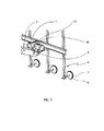
さて図2を参照すると、前記可動支持要素3はゴムホイールから構成され、各ホイールはシャフト12の端部に取付けられている。もし必要なら、シャフト12の長さは、シャシーに固定されたボックスビーム12b及びその中に受け入れられたスライド軸ビーム12aを持つ伸縮自在性であることにより延ばされることができる。図2に示された伸縮自在の解決策は、必要なときにホイールベースを増大するために前部ホイール3で使用される。前部ホイール3は、ホイールベースが調整される間、回転または静止することができる。通常、車両1の後部は、車両の操縦性を改善するために一つのホイールまたは二つの密接に配置されたホイールのいずれかを備えている。全てのホイール3は、通路等の最小幅を必要とするために車両1の周囲の内側に保持される。
Referring now to FIG. 2, the
材料運搬ラック6は、ブラケット9、第一作動器10及び第二作動器11を含む多軸ジョイント(図3)により張り出し棒5に連結され、それによりブラケット9は、伸縮自在の張り出し棒5の自由端のピボット13周りにかつ前記自由端に対して垂直面内で回転することができる。第一作動器10はブラケット9中に組み込まれかつブラケット9とともに動き、従って上述の垂直面内で可動であり、作動器10は第二作動器11と直角を規定し、前記作動器11を回転することができ、それはまたラック6を回転する。
The material carrying
把持手段は、必要な減圧を提供するために吸引管(図示せず)のための開口を備えた大きな平坦なカップ7であり、各カップ7の縁は、把持される材料に対して気密にロックされるように柔らかい可撓性材料8により覆われる。減圧源は図示されていない。
The gripping means is a large
これに代えて、もし運ばれる材料が磁性であるなら、カップ7は電源(図示せず)から荷電された電磁石であることができるだろう。
Alternatively, if the material being carried is magnetic, the
塔4の上部近くのピボット14(図1及び2)は、張り出し棒5の固定端を垂直面内で旋回させるための中心として作用する。塔4は車両の長手方向に対して少なくとも+/−90°の範囲内で垂直軸周りにターンテーブルにより回転でき、かくしてそれは車両1と並んだ位置で保持されたラック6を動かすことができる。
A pivot 14 (FIGS. 1 and 2) near the top of the
塔4の旋回点14は前記垂直回転軸からオフセットしており、それは吊上げ操作時の安定性に関して処理する運動量を低くする。
The
車両1の好適な実施態様は操作者のための座席を与えず、吊上げ操作はリモートコントロールユニットから制御される。 The preferred embodiment of the vehicle 1 does not provide a seat for the operator and the lifting operation is controlled from a remote control unit.
吊上げられる材料は実質的に平坦な形のあらゆる種類の材料、例えば、ガラス、プラスチック、木材、花崗岩、石膏または鋼等のパネルであることができる。 The material to be lifted can be any kind of material in a substantially flat shape, for example a panel of glass, plastic, wood, granite, gypsum or steel.
Claims (15)
Applications Claiming Priority (1)
| Application Number | Priority Date | Filing Date | Title |
|---|---|---|---|
| PCT/IB2008/002755 WO2010043919A1 (en) | 2008-10-17 | 2008-10-17 | Lifting vehicle |
Publications (2)
| Publication Number | Publication Date |
|---|---|
| JP2012505806A true JP2012505806A (en) | 2012-03-08 |
| JP5371019B2 JP5371019B2 (en) | 2013-12-18 |
Family
ID=40810146
Family Applications (1)
| Application Number | Title | Priority Date | Filing Date |
|---|---|---|---|
| JP2011531575A Expired - Fee Related JP5371019B2 (en) | 2008-10-17 | 2008-10-17 | Lifting vehicle |
Country Status (8)
| Country | Link |
|---|---|
| US (1) | US20110264306A1 (en) |
| EP (1) | EP2349907A1 (en) |
| JP (1) | JP5371019B2 (en) |
| CN (1) | CN102186762B (en) |
| AU (2) | AU2008363079A1 (en) |
| CA (1) | CA2739247A1 (en) |
| RU (1) | RU2492133C2 (en) |
| WO (1) | WO2010043919A1 (en) |
Cited By (1)
| Publication number | Priority date | Publication date | Assignee | Title |
|---|---|---|---|---|
| JP2013508244A (en) * | 2009-10-21 | 2013-03-07 | エイチエイチ インテリテック エーピーエス | Adjusting head for lifting device |
Families Citing this family (32)
| Publication number | Priority date | Publication date | Assignee | Title |
|---|---|---|---|---|
| US9462734B2 (en) | 2010-04-27 | 2016-10-04 | Alion Energy, Inc. | Rail systems and methods for installation and operation of photovoltaic arrays |
| US9343592B2 (en) | 2010-08-03 | 2016-05-17 | Alion Energy, Inc. | Electrical interconnects for photovoltaic modules and methods thereof |
| US9641123B2 (en) | 2011-03-18 | 2017-05-02 | Alion Energy, Inc. | Systems for mounting photovoltaic modules |
| US20130047908A1 (en) * | 2011-08-29 | 2013-02-28 | General Electric Company | Marine turbine lift |
| US9352941B2 (en) | 2012-03-20 | 2016-05-31 | Alion Energy, Inc. | Gantry crane vehicles and methods for photovoltaic arrays |
| CN102674207B (en) * | 2012-05-05 | 2015-06-24 | 无锡市新华起重工具有限公司 | Forklift sling |
| JP6278958B2 (en) | 2012-05-16 | 2018-02-14 | アリオン エナジー,インコーポレーテッド | Rotating support system and method for photovoltaic modules |
| BE1021277B1 (en) * | 2013-04-24 | 2015-10-13 | Tom Thomas | MAGNETIC HOOK FOR DETERMINING AND RELEASING MAGNETIC MATERIALS |
| JP6475246B2 (en) | 2013-09-05 | 2019-02-27 | アリオン エナジー,インコーポレーテッド | System, vehicle and method for maintaining a rail-based array of photovoltaic modules |
| US9453660B2 (en) | 2013-09-11 | 2016-09-27 | Alion Energy, Inc. | Vehicles and methods for magnetically managing legs of rail-based photovoltaic modules during installation |
| PL3134338T3 (en) * | 2014-04-24 | 2021-09-27 | Quantum Workhealth Programmes Pty Ltd | A device for lifting and transporting sheet material |
| CN104035220A (en) * | 2014-05-30 | 2014-09-10 | 京东方科技集团股份有限公司 | Rotation device |
| US9995047B2 (en) * | 2015-06-09 | 2018-06-12 | Integrated Construction Enterprises, Inc. | Construction board installation robot |
| US11919019B2 (en) | 2015-06-17 | 2024-03-05 | Revolutionice Inc. | Autonomous painting systems and related methods |
| US10124359B2 (en) | 2015-06-17 | 2018-11-13 | Integrated Construction Enterprises, Inc. | Autonomous painting systems and related methods |
| WO2017044566A1 (en) | 2015-09-11 | 2017-03-16 | Alion Energy, Inc. | Wind screens for photovoltaic arrays and methods thereof |
| CN105293390A (en) * | 2015-10-16 | 2016-02-03 | 徐州重型机械有限公司 | Work platform leveling system and elevating platform fire fighting truck using same |
| PE20181278A1 (en) * | 2015-10-22 | 2018-08-07 | Vacuworx Global Llc | QUICK DISCONNECT TRUCK MOUNTED VACUUM MATERIAL HANDLER |
| DK179078B1 (en) * | 2016-03-01 | 2017-10-09 | Smart Lift As | Compact ergonomic self-propelled lifting machine |
| BE1023719B1 (en) * | 2016-05-11 | 2017-06-26 | Vervaeke-Belavi Nv | Method for transferring pre-incubated eggs to a broiler house and the consultation machine used for this |
| BE1024985B1 (en) * | 2017-07-05 | 2018-09-05 | Vervaeke Belavi Nv | Transfer machine for laying eggs in a poultry shed on a floor thereof in hatching drawers in which they were pre-incubated |
| CN107226423B (en) * | 2017-08-07 | 2018-08-24 | 哈工大机器人集团(广州)知识产权投资控股有限公司哈尔滨分公司 | A kind of special granite vehicle resistance stone of blocking vehicular traffic captures suspension transferring machine automatically |
| IT201800004152A1 (en) * | 2018-03-30 | 2019-09-30 | Manitou Italia Srl | Remote controlled telehandler. |
| CN108829976B (en) * | 2018-06-20 | 2021-04-16 | 吉林大学 | Method for determining automobile driving stability region of multi-degree-of-freedom system |
| CN109795867B (en) * | 2019-03-12 | 2024-07-23 | 广东西江数据科技有限公司 | Automatic loading and unloading device for server |
| BE1027307B1 (en) * | 2019-05-24 | 2020-12-22 | Vervaeke Belavi | Overlay machine and use thereof for presenting incubated eggs on a floor thereof in a poultry house |
| NL2023445B1 (en) | 2019-07-05 | 2021-02-02 | Baars Hendrik | An apparatus for operating a tool, as well as a method for moving an object |
| NL2023446B1 (en) | 2019-07-05 | 2021-02-02 | Baars Gerrit | An articulated device, an apparatus for operating a tool, as well as a method for moving an object |
| CN111960333B (en) * | 2020-07-27 | 2022-03-15 | 南京欧弈物流设备制造有限公司 | Clamp for mounting on-site lifting frame column piece and using method thereof |
| GB2602125A (en) * | 2020-12-18 | 2022-06-22 | Bamford Excavators Ltd | A carriage assembly |
| CN113479648B (en) * | 2021-07-08 | 2023-08-01 | 彩虹(合肥)液晶玻璃有限公司 | Glass substrate carrying device |
| CN114379999B (en) * | 2022-03-22 | 2022-06-07 | 天津通广集团专用设备有限公司 | Automatic unloading system of container |
Citations (10)
| Publication number | Priority date | Publication date | Assignee | Title |
|---|---|---|---|---|
| JPS506700B1 (en) * | 1970-09-26 | 1975-03-17 | ||
| JPS51136263U (en) * | 1975-04-25 | 1976-11-04 | ||
| JPS5347789Y2 (en) * | 1975-06-05 | 1978-11-15 | ||
| JPS60130290U (en) * | 1984-02-09 | 1985-08-31 | 愛知車輛株式会社 | Fall prevention device for self-propelled aerial work vehicles |
| US4676713A (en) * | 1985-12-06 | 1987-06-30 | Voelpel Charles E | Material handling machine |
| JPH0162297U (en) * | 1987-10-14 | 1989-04-20 | ||
| JPH04343975A (en) * | 1991-05-20 | 1992-11-30 | Komatsu Ltd | Truck of construction site working machine |
| JPH10146781A (en) * | 1996-09-17 | 1998-06-02 | Kobelco Kenki Eng Kk | Glass handling machine, and handling device therefor |
| JP2000072393A (en) * | 1998-08-28 | 2000-03-07 | Toyota Autom Loom Works Ltd | Three-wheel type forklift truck |
| JP2003312973A (en) * | 2002-04-16 | 2003-11-06 | Furukawa Co Ltd | Magnet device for working vehicle |
Family Cites Families (19)
| Publication number | Priority date | Publication date | Assignee | Title |
|---|---|---|---|---|
| US3630389A (en) * | 1970-09-30 | 1971-12-28 | Gen Electric | Material-handling apparatus |
| US4039094A (en) * | 1975-12-23 | 1977-08-02 | Fulton Industries, Inc. | Aerial lift platform with extendable wheels |
| JPS5370537U (en) * | 1976-11-15 | 1978-06-13 | ||
| DE7805924U1 (en) * | 1978-02-27 | 1978-06-08 | Weber, Hans Heinrich, Dipl.-Ing., 2800 Bremen | MOBILE LIFTING DEVICE |
| US4280785A (en) * | 1979-05-09 | 1981-07-28 | Wismer & Becker Contracting Engineers | Multi-directional lifting and handling attachment for a crane boom |
| GB2082984B (en) * | 1980-09-03 | 1984-02-08 | Coles Cranes Ltd | Chassis for platform vehicles |
| US4456093A (en) * | 1981-06-16 | 1984-06-26 | Interstate Electronics Corp. | Control system for aerial work platform machine and method of controlling an aerial work platform machine |
| SU1512907A1 (en) * | 1987-12-08 | 1989-10-07 | Днепропетровский инженерно-строительный институт | Load engaging device |
| SE503880C2 (en) * | 1994-03-23 | 1996-09-23 | Jan Erik Johansson | magnetic |
| US5584646A (en) * | 1994-08-31 | 1996-12-17 | Wiseda Ltd. | Handling apparatus |
| US6119882A (en) * | 1998-12-04 | 2000-09-19 | Upright, Inc. | Self-propelled boom with extendible axles |
| SG82672A1 (en) * | 1999-02-04 | 2001-08-21 | Snorkel International Inc | Aerial work platform boom having ground and platform controls linked by a controller area network |
| GB9906213D0 (en) * | 1999-03-18 | 1999-05-12 | G G R Glass Services Limited | Panel manipulation device |
| JP2001019386A (en) * | 1999-07-07 | 2001-01-23 | Koa:Kk | Glass attaching executing machine, and glass sucking device |
| US6827176B2 (en) * | 2003-01-07 | 2004-12-07 | Jlg Industries, Inc. | Vehicle with offset extendible axles and independent four-wheel steering control |
| ES2378824T3 (en) * | 2004-03-30 | 2012-04-18 | Jlg Industries, Inc. | Fixing device for a telescopic material handler to handle a load with five degrees of freedom |
| ITPD20050055A1 (en) * | 2005-03-01 | 2006-09-02 | Antonio Piazza | EQUIPMENT FOR WITHDRAWAL AND TRANSPORT OF LASTRIFORMS PRODUCTS STORED IN A STORAGE WAREHOUSE |
| FR2896784B1 (en) * | 2006-02-01 | 2008-07-04 | Colin Jean Pierre Marie | CHARGE PREVENTING APPARATUS (S), PREFERABLY OF THE PANEL TYPE, IN PARTICULAR FOR TRANSFERRING THE LOAD OR LOAD BETWEEN TWO SITES |
| US8352129B2 (en) * | 2008-10-16 | 2013-01-08 | Eaton Corporation | Motion control of work vehicle |
-
2008
- 2008-10-17 EP EP08875713A patent/EP2349907A1/en not_active Withdrawn
- 2008-10-17 RU RU2011119629/11A patent/RU2492133C2/en not_active IP Right Cessation
- 2008-10-17 US US13/124,442 patent/US20110264306A1/en not_active Abandoned
- 2008-10-17 AU AU2008363079A patent/AU2008363079A1/en not_active Abandoned
- 2008-10-17 JP JP2011531575A patent/JP5371019B2/en not_active Expired - Fee Related
- 2008-10-17 CA CA2739247A patent/CA2739247A1/en not_active Abandoned
- 2008-10-17 WO PCT/IB2008/002755 patent/WO2010043919A1/en active Application Filing
- 2008-10-17 CN CN200880131565.6A patent/CN102186762B/en not_active Expired - Fee Related
-
2016
- 2016-02-23 AU AU2016201114A patent/AU2016201114A1/en not_active Abandoned
Patent Citations (10)
| Publication number | Priority date | Publication date | Assignee | Title |
|---|---|---|---|---|
| JPS506700B1 (en) * | 1970-09-26 | 1975-03-17 | ||
| JPS51136263U (en) * | 1975-04-25 | 1976-11-04 | ||
| JPS5347789Y2 (en) * | 1975-06-05 | 1978-11-15 | ||
| JPS60130290U (en) * | 1984-02-09 | 1985-08-31 | 愛知車輛株式会社 | Fall prevention device for self-propelled aerial work vehicles |
| US4676713A (en) * | 1985-12-06 | 1987-06-30 | Voelpel Charles E | Material handling machine |
| JPH0162297U (en) * | 1987-10-14 | 1989-04-20 | ||
| JPH04343975A (en) * | 1991-05-20 | 1992-11-30 | Komatsu Ltd | Truck of construction site working machine |
| JPH10146781A (en) * | 1996-09-17 | 1998-06-02 | Kobelco Kenki Eng Kk | Glass handling machine, and handling device therefor |
| JP2000072393A (en) * | 1998-08-28 | 2000-03-07 | Toyota Autom Loom Works Ltd | Three-wheel type forklift truck |
| JP2003312973A (en) * | 2002-04-16 | 2003-11-06 | Furukawa Co Ltd | Magnet device for working vehicle |
Cited By (1)
| Publication number | Priority date | Publication date | Assignee | Title |
|---|---|---|---|---|
| JP2013508244A (en) * | 2009-10-21 | 2013-03-07 | エイチエイチ インテリテック エーピーエス | Adjusting head for lifting device |
Also Published As
| Publication number | Publication date |
|---|---|
| EP2349907A1 (en) | 2011-08-03 |
| WO2010043919A8 (en) | 2011-05-05 |
| RU2492133C2 (en) | 2013-09-10 |
| CN102186762B (en) | 2014-05-07 |
| WO2010043919A1 (en) | 2010-04-22 |
| AU2008363079A1 (en) | 2010-04-22 |
| CN102186762A (en) | 2011-09-14 |
| US20110264306A1 (en) | 2011-10-27 |
| AU2016201114A1 (en) | 2016-03-10 |
| JP5371019B2 (en) | 2013-12-18 |
| CA2739247A1 (en) | 2010-04-22 |
| RU2011119629A (en) | 2012-11-27 |
Similar Documents
| Publication | Publication Date | Title |
|---|---|---|
| JP5371019B2 (en) | Lifting vehicle | |
| US7997845B2 (en) | Glass handling systems | |
| US20100170747A1 (en) | Apparatus for elevating and positioning a work platform | |
| US7581915B1 (en) | Drywall lift assembly including a center telescopically extendable lifting means | |
| US10961728B2 (en) | Wheeled concrete supply hose moving device | |
| CN104108411B (en) | Self-propel Accessory | |
| US5147170A (en) | Power-driven adjustable equipment rack carrier | |
| US20190247967A1 (en) | Gravity assist system | |
| JPS59501705A (en) | Movable machine chassis assembly | |
| US20220315085A1 (en) | Portable load lift device | |
| US20240199385A1 (en) | Cantilever hoist device | |
| US4268216A (en) | Load lifting and carrying machine | |
| JPH0747439Y2 (en) | Plate material transfer device | |
| JP3657101B2 (en) | Wagon with auxiliary power mechanism | |
| JP5818884B2 (en) | Vehicles that carry ballast weights | |
| JP2858192B2 (en) | Interior material transport mounting device | |
| JPH0249098Y2 (en) | ||
| JPH069199A (en) | Frame conveying device | |
| JPH06219698A (en) | Running type heavy object handling device |
Legal Events
| Date | Code | Title | Description |
|---|---|---|---|
| A977 | Report on retrieval |
Free format text: JAPANESE INTERMEDIATE CODE: A971007 Effective date: 20121214 |
|
| A131 | Notification of reasons for refusal |
Free format text: JAPANESE INTERMEDIATE CODE: A131 Effective date: 20121221 |
|
| A521 | Request for written amendment filed |
Free format text: JAPANESE INTERMEDIATE CODE: A523 Effective date: 20130321 |
|
| TRDD | Decision of grant or rejection written | ||
| A01 | Written decision to grant a patent or to grant a registration (utility model) |
Free format text: JAPANESE INTERMEDIATE CODE: A01 Effective date: 20130816 |
|
| A61 | First payment of annual fees (during grant procedure) |
Free format text: JAPANESE INTERMEDIATE CODE: A61 Effective date: 20130911 |
|
| R150 | Certificate of patent or registration of utility model |
Free format text: JAPANESE INTERMEDIATE CODE: R150 |
|
| R250 | Receipt of annual fees |
Free format text: JAPANESE INTERMEDIATE CODE: R250 |
|
| LAPS | Cancellation because of no payment of annual fees |