JP2012505672A - Intramedullary nail - Google Patents
Intramedullary nail Download PDFInfo
- Publication number
- JP2012505672A JP2012505672A JP2011531392A JP2011531392A JP2012505672A JP 2012505672 A JP2012505672 A JP 2012505672A JP 2011531392 A JP2011531392 A JP 2011531392A JP 2011531392 A JP2011531392 A JP 2011531392A JP 2012505672 A JP2012505672 A JP 2012505672A
- Authority
- JP
- Japan
- Prior art keywords
- intramedullary nail
- proximal
- distal
- longitudinal axis
- notch
- Prior art date
- Legal status (The legal status is an assumption and is not a legal conclusion. Google has not performed a legal analysis and makes no representation as to the accuracy of the status listed.)
- Granted
Links
- 230000007704 transition Effects 0.000 claims description 45
- 238000000926 separation method Methods 0.000 claims 4
- 238000009826 distribution Methods 0.000 abstract description 7
- 239000000463 material Substances 0.000 description 29
- 238000005520 cutting process Methods 0.000 description 26
- 210000000689 upper leg Anatomy 0.000 description 19
- 210000000988 bone and bone Anatomy 0.000 description 11
- 238000004519 manufacturing process Methods 0.000 description 6
- 206010017076 Fracture Diseases 0.000 description 5
- 208000010392 Bone Fractures Diseases 0.000 description 4
- 230000001154 acute effect Effects 0.000 description 4
- 230000000399 orthopedic effect Effects 0.000 description 3
- 230000008468 bone growth Effects 0.000 description 2
- 210000003275 diaphysis Anatomy 0.000 description 2
- 238000006073 displacement reaction Methods 0.000 description 2
- 210000002082 fibula Anatomy 0.000 description 2
- 239000007943 implant Substances 0.000 description 2
- 238000003754 machining Methods 0.000 description 2
- 210000002303 tibia Anatomy 0.000 description 2
- 208000008924 Femoral Fractures Diseases 0.000 description 1
- 229910001069 Ti alloy Inorganic materials 0.000 description 1
- 229910000883 Ti6Al4V Inorganic materials 0.000 description 1
- WAIPAZQMEIHHTJ-UHFFFAOYSA-N [Cr].[Co] Chemical class [Cr].[Co] WAIPAZQMEIHHTJ-UHFFFAOYSA-N 0.000 description 1
- 210000003484 anatomy Anatomy 0.000 description 1
- 230000015572 biosynthetic process Effects 0.000 description 1
- 238000005266 casting Methods 0.000 description 1
- 230000008859 change Effects 0.000 description 1
- 238000006243 chemical reaction Methods 0.000 description 1
- 210000003109 clavicle Anatomy 0.000 description 1
- 239000012141 concentrate Substances 0.000 description 1
- 238000007796 conventional method Methods 0.000 description 1
- 230000000694 effects Effects 0.000 description 1
- 208000020089 femoral neck fracture Diseases 0.000 description 1
- 210000002436 femur neck Anatomy 0.000 description 1
- 238000005242 forging Methods 0.000 description 1
- 208000014674 injury Diseases 0.000 description 1
- 230000003993 interaction Effects 0.000 description 1
- 238000000034 method Methods 0.000 description 1
- 230000000717 retained effect Effects 0.000 description 1
- 239000010935 stainless steel Substances 0.000 description 1
- 229910001220 stainless steel Inorganic materials 0.000 description 1
- 210000001519 tissue Anatomy 0.000 description 1
- 230000008733 trauma Effects 0.000 description 1
- 210000000623 ulna Anatomy 0.000 description 1
Images


Classifications
-
- A—HUMAN NECESSITIES
- A61—MEDICAL OR VETERINARY SCIENCE; HYGIENE
- A61B—DIAGNOSIS; SURGERY; IDENTIFICATION
- A61B17/00—Surgical instruments, devices or methods, e.g. tourniquets
- A61B17/56—Surgical instruments or methods for treatment of bones or joints; Devices specially adapted therefor
- A61B17/58—Surgical instruments or methods for treatment of bones or joints; Devices specially adapted therefor for osteosynthesis, e.g. bone plates, screws, setting implements or the like
- A61B17/68—Internal fixation devices, including fasteners and spinal fixators, even if a part thereof projects from the skin
- A61B17/72—Intramedullary pins, nails or other devices
- A61B17/7233—Intramedullary pins, nails or other devices with special means of locking the nail to the bone
- A61B17/7241—Intramedullary pins, nails or other devices with special means of locking the nail to the bone the nail having separate elements through which screws pass
-
- A—HUMAN NECESSITIES
- A61—MEDICAL OR VETERINARY SCIENCE; HYGIENE
- A61B—DIAGNOSIS; SURGERY; IDENTIFICATION
- A61B17/00—Surgical instruments, devices or methods, e.g. tourniquets
- A61B17/56—Surgical instruments or methods for treatment of bones or joints; Devices specially adapted therefor
- A61B17/58—Surgical instruments or methods for treatment of bones or joints; Devices specially adapted therefor for osteosynthesis, e.g. bone plates, screws, setting implements or the like
- A61B17/68—Internal fixation devices, including fasteners and spinal fixators, even if a part thereof projects from the skin
- A61B17/72—Intramedullary pins, nails or other devices
- A61B17/7283—Intramedullary pins, nails or other devices with special cross-section of the nail
-
- A—HUMAN NECESSITIES
- A61—MEDICAL OR VETERINARY SCIENCE; HYGIENE
- A61B—DIAGNOSIS; SURGERY; IDENTIFICATION
- A61B17/00—Surgical instruments, devices or methods, e.g. tourniquets
- A61B17/56—Surgical instruments or methods for treatment of bones or joints; Devices specially adapted therefor
- A61B17/58—Surgical instruments or methods for treatment of bones or joints; Devices specially adapted therefor for osteosynthesis, e.g. bone plates, screws, setting implements or the like
- A61B17/68—Internal fixation devices, including fasteners and spinal fixators, even if a part thereof projects from the skin
- A61B17/74—Devices for the head or neck or trochanter of the femur
- A61B17/742—Devices for the head or neck or trochanter of the femur having one or more longitudinal elements oriented along or parallel to the axis of the neck
- A61B17/744—Devices for the head or neck or trochanter of the femur having one or more longitudinal elements oriented along or parallel to the axis of the neck the longitudinal elements coupled to an intramedullary nail
-
- A—HUMAN NECESSITIES
- A61—MEDICAL OR VETERINARY SCIENCE; HYGIENE
- A61B—DIAGNOSIS; SURGERY; IDENTIFICATION
- A61B17/00—Surgical instruments, devices or methods, e.g. tourniquets
- A61B17/56—Surgical instruments or methods for treatment of bones or joints; Devices specially adapted therefor
- A61B17/58—Surgical instruments or methods for treatment of bones or joints; Devices specially adapted therefor for osteosynthesis, e.g. bone plates, screws, setting implements or the like
- A61B17/68—Internal fixation devices, including fasteners and spinal fixators, even if a part thereof projects from the skin
- A61B17/72—Intramedullary pins, nails or other devices
- A61B17/7291—Intramedullary pins, nails or other devices for small bones, e.g. in the foot, ankle, hand or wrist
Abstract
本発明は、横穴(48)が貫通した本体と、横穴の少なくとも外側において応力分布が向上された領域と、を有する髄内釘(30)を提供する。一実施例では、髄内釘は、傾斜した切欠き部などの、横穴に隣接した切欠き部(32,56,70,84)を含み、横穴の外側開口部の周りの領域における髄内釘の応力分布を向上させる。一実施例では、切欠き部は、傾斜部(78,94)、すなわち横穴の外側開口部を画定する領域を含む。その他の実施例では、切欠き部は、逃げ部(60)、すなわち横穴の外側開口部を画定する実質的に平坦な部分を画定する。 The present invention provides an intramedullary nail (30) having a body through which a lateral hole (48) passes and a region having improved stress distribution at least outside the lateral hole. In one embodiment, the intramedullary nail includes a notch (32, 56, 70, 84) adjacent to the lateral hole, such as an angled notch, and an intramedullary nail in the region around the outer opening of the lateral hole. Improve the stress distribution. In one embodiment, the notch includes a ramp (78, 94), i.e., a region that defines an outer opening of the lateral hole. In other embodiments, the notch defines a relief (60), ie, a substantially flat portion that defines the outer opening of the lateral hole.
Description
本発明は整形外科用部品に関し、特に髄内釘に関する。 The present invention relates to orthopedic components, and more particularly to intramedullary nails.
大腿骨などの長骨の骨折部分を調整し、安定させるように髄内釘が用いられる。骨折した大腿骨では、髄内釘が大腿骨の髄内管に挿入されて大腿骨の骨折線を横切って延在するように配置される。次いで、骨折した大腿骨の両側にねじもしくはその他の固定装置を髄内釘に形成された穴を通して挿入して、骨折した大腿骨の対向する部分を固定する。 Intramedullary nails are used to adjust and stabilize fractures of long bones such as the femur. In a fractured femur, an intramedullary nail is placed into the intramedullary canal of the femur and positioned to extend across the femoral fracture line. A screw or other fixation device is then inserted through the hole formed in the intramedullary nail on either side of the fractured femur to fix the opposing portions of the fractured femur.
大腿骨頭および/または大腿骨頸などの長骨頭や長骨頸が骨折した場合、髄内釘に形成された横穴にラグスクリューが挿入される。この穴はラグスクリューが頸部を通して長骨の頭部へと骨折線を横切って延在するように位置合わせされ、それによりラグスクリューが長骨の頭部および/または頸部の骨折を軽減する。 When a long bone head such as a femoral head and / or a femoral neck or a long bone neck breaks, a lag screw is inserted into a lateral hole formed in the intramedullary nail. This hole is aligned so that the lag screw extends across the fracture line through the neck to the long bone head, thereby reducing the long bone head and / or neck fracture .
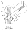
例えば、図1を参照すると、大腿骨10が骨幹部12と、頸部14と、頭部16と、を含むように示す。図示のように、大腿骨10の頸部14は線17で骨折している。横穴18が髄内釘20を通して延在するとともに、その穴を通してラグスクリュー22を収容するように寸法が取られる。特に、ラグスクリュー22は横穴18の直径よりも僅かに小さい外径を有する。これによりラグスクリュー22が横穴18に挿通されて、線17における骨折を軽減する。
For example, referring to FIG. 1, the
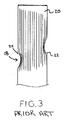
しかしながら、ラグスクリュー22が横穴18の直径よりも小さい外径を有する必要があるため、ラグスクリュー22の端部に力が加えられたときにラグスクリュー22が髄内釘20の横穴18内で僅かに旋回する。例えば、人の体重を支える大腿骨10の頭部16に起因してラグスクリュー22の端部に力FGが加えられる。ラグスクリュー22の端部に力FGが加えられたとき、髄内釘20の横穴18内でラグスクリュー22が僅かに旋回し、結果として生じる力を支える2つの支持点が形成される。第1の支持点24は、ラグスクリュー22に力FMが作用する、内側、遠位の支持点であり、第2の支持点26は、ラグスクリュー22に力FLが作用する、外側、近位の支持点である。第1および第2の支持点24,26に力を及ぼすことにより、力FMが髄内釘20の下部の主要部に圧縮応力を誘発する一方で、力FLが横穴18の領域に引張応力を誘発する。さらに、横穴18内のラグスクリュー22のてこ率により、支持点26上に及ぼされる力FLが増幅される。結果として生じる理論的な応力分布を図3に示し、横穴18の内側および外側開口部の周りに応力が集中している。
However, since the
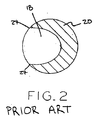
髄内釘20の断面を示す図2を参照すると、力FLに起因するマキシマム・テンションが横穴18の外側開口部付近に見られ、この横穴18は深刻な臨界形状を有する領域に形成された鋭角部27を有する。髄内釘20の最も外側に発生するマキシマム・テンションに加えて、髄内釘20の横穴18の形成により、僅かな量の部品材料しか備えていない横穴18の外側開口部の鋭角部27に沿って応力を更に集中させる切欠き効果を生じさせる。特に、横穴18の外側開口部の周りの領域には、例えば髄内釘20の形状の結果としてその上部には僅かな量の材料しか備えていない。別の言い方をすれば、髄内釘20はその長手方向軸に対して垂直な方向に実質的に環状の断面を有し、横穴18の外側開口部が髄内釘20の外縁部に配置されるため、髄内釘20の長手方向軸に近い領域における材料の量に比べ、支持点26の領域および横穴18の外側開口部には僅かな量の材料しか備えていない。横穴18の外側開口部の領域に僅かな量の材料しか存在していない結果、横穴18の外側開口部の領域の材料には、髄内釘20の長手方向軸により近い材料に比べてより大きな応力が集中する。これにより、横穴18の外側開口部に近接する材料において増大する応力集中に耐えるように、髄内釘20がより強力かつより高価な材料から形成される必要があり、かつ/または、横穴18の外側開口部に近接して存在する材料の体積を増やし、かつ応力集中を低下させるように、横穴18の外側開口部近傍の髄内釘20の領域の大きさを増加させる必要がある。特許文献1は、穴の外側端部に局所的な陥凹部を有し、その陥凹部が鋭利な遠位側縁部への曲線的な移行部を有する髄内釘を開示している。
Referring to FIG. 2, which shows a cross-section of the
本発明は、横穴が貫通した本体と、横穴の少なくとも外側において応力分布が向上された領域と、を有する髄内釘を提供する。一実施例では、髄内釘は、傾斜した切欠き部などの、横穴に隣接した切欠き部を含み、横穴の外側開口部の周りの領域における髄内釘の応力分布を向上させる。一実施例では、切欠き部は、傾斜部、すなわち横穴の外側開口部を画定する領域を含む。その他の実施例では、切欠き部の傾斜部は、逃げ部、すなわち横穴の外側開口部を画定する実質的に平坦な部分を画定する。 The present invention provides an intramedullary nail having a body through which a lateral hole penetrates and a region having improved stress distribution at least outside the lateral hole. In one embodiment, the intramedullary nail includes a notch adjacent to the lateral hole, such as a sloped notch, to improve the stress distribution of the intramedullary nail in the region around the outer opening of the lateral hole. In one embodiment, the notch includes a ramp, ie, a region that defines an outer opening of the side hole. In other embodiments, the notch ramp defines a relief, i.e., a substantially flat portion that defines the outer opening of the side hole.
特に、本発明の教示に従って髄内釘の横穴に隣接して切欠き部を形成させる際、以下に詳述するように、横穴の遠位側に配置された材料および/または横穴の外側開口部に隣接する材料が除去される。しかしながら、横穴の近位側に隣接する材料は保持される。例えば、横穴に隣接する領域が実質的に円筒形状を有する従来の髄内釘と比較して、本発明の髄内釘では、横穴の外側開口部からすぐ遠位側の領域および/または横穴の外側開口部に隣接する領域には材料がない。横穴の遠位側に材料を備えていないように製造することにより、外側支持点54(図4A)の遠位の領域等の、髄内釘の外側開口部に応力が誘発され、髄内釘の長手方向軸に向かう方向に応力が分散される。その結果、外側支持点に誘発される応力が髄内釘の異なる部位、すなわち、横穴の外側開口部にすぐに隣接する材料に関して、髄内釘の長手方向軸からの横方向距離が小さくなって隙間が空けられた部位を通して分散される。これにより応力が髄内釘の本体全体に亘って分散されるため、横穴の外側開口部に隣接する横方向支持点における応力集中を軽減することが可能となる。 In particular, when forming a notch adjacent to a lateral hole of an intramedullary nail in accordance with the teachings of the present invention, the material disposed on the distal side of the lateral hole and / or the outer opening of the lateral hole, as described in detail below The material adjacent to is removed. However, the material adjacent to the proximal side of the side hole is retained. For example, compared to a conventional intramedullary nail in which the region adjacent to the lateral hole has a substantially cylindrical shape, the intramedullary nail of the present invention has a region immediately distal to the outer opening of the lateral hole and / or the lateral hole. There is no material in the region adjacent to the outer opening. Manufacture without material on the distal side of the side hole induces stress in the outer opening of the intramedullary nail, such as the distal region of the outer support point 54 (FIG. 4A), and the intramedullary nail Stress is distributed in a direction toward the longitudinal axis of the. As a result, the lateral distance from the longitudinal axis of the intramedullary nail is reduced for different parts of the intramedullary nail where the stress induced at the outer support point is immediately adjacent to the outer opening of the lateral hole. Dispersed through the gaps. This distributes the stress across the entire body of the intramedullary nail, thus reducing stress concentration at the lateral support points adjacent to the outer opening of the lateral hole.
本発明の各々の実施例では、髄内釘に形成される切欠き部はその遠位側端部に鋭角を持たない。代わりに、本発明の各実施例は切欠き部の遠位側端部に緩やかな移行領域を利用する。上述したように、一実施例では、緩やかな移行領域は、髄内釘の軸に平行に延在するとともに髄内釘の中間部で終端する逃げ部として、切欠き部の遠位側端部に形成される。別の実施例では、切欠き部の遠位部は、髄内釘の近位部における外面の遠位で終端する斜角面を形成するとともに、髄内釘の長手方向軸と角度を形成する。切欠き部の斜角の遠位表面部分が髄内釘の長手方向軸とともに形成する角度を変更することにより、髄内釘の特定の応力伝達特性が特定の用途に応じて修正され、かつ/または、最適化される。 In each embodiment of the present invention, the notch formed in the intramedullary nail does not have an acute angle at its distal end. Instead, each embodiment of the present invention utilizes a gradual transition region at the distal end of the notch. As described above, in one embodiment, the gradual transition region extends parallel to the axis of the intramedullary nail and serves as a relief that terminates in the middle of the intramedullary nail as the distal end of the notch. Formed. In another embodiment, the distal portion of the notch forms a beveled surface that terminates distally of the outer surface at the proximal portion of the intramedullary nail and forms an angle with the longitudinal axis of the intramedullary nail. . By changing the angle that the beveled distal surface portion of the notch forms with the longitudinal axis of the intramedullary nail, certain stress transfer characteristics of the intramedullary nail are modified for a particular application, and / or Or it is optimized.
さらに、切欠き部の遠位端部における鋭角を緩やかな移行領域に置き換えることにより、高い、振動する引張応力に曝される髄内釘の部位が取り除かれる。さらに、たとえ切欠き部の領域内に骨成長が生じたとしても、髄内釘を患者の体から容易に取り除くことができる。特に、海綿様骨組織が切欠き部によって画定される領域内へと成長した場合、髄内釘を取り除くときに、切欠き部の遠位端部を画定する表面が弾力性のある海綿様骨組織を一時的に移動させ、髄内釘が移動された骨に沿って円滑に滑るのを可能にする。次に、ひとたび髄内釘が取り除かれると、以前髄内釘によって占められていた海綿様骨組織内の空間に骨組織が再び広がる。その結果、髄内釘が取り除かれた場合に骨組織の外傷が実質的に軽減される。 Further, by replacing the acute angle at the distal end of the notch with a gentle transition region, the site of the intramedullary nail exposed to high, oscillating tensile stress is removed. Furthermore, the intramedullary nail can be easily removed from the patient's body even if bone growth occurs in the area of the notch. In particular, if the cancellous bone tissue has grown into the area defined by the notch, the surface that defines the distal end of the notch is elastic when the intramedullary nail is removed. The tissue is moved temporarily, allowing the intramedullary nail to slide smoothly along the moved bone. Next, once the intramedullary nail is removed, the bone tissue re-expands into the space within the cancellous bone tissue previously occupied by the intramedullary nail. As a result, bone tissue trauma is substantially reduced when the intramedullary nail is removed.
本明細書全体を通して、遠位(distal)、近位(proximal)、内側(medial)、外側(lateral)、前部(anterior)、および後部(posterior)などの種々の位置に関する用語は、人体解剖学を参照するときに慣習的に用いられる。さらに具体的には、「遠位」は、人体への連結点から離れる領域を表し、「近位」は人体への連結点に近い領域を表す。例えば、大腿近位部は、大腿骨の臀部に近い部分を表し、大腿遠位部は、大腿骨の脛骨に近い部分を表す。用語「内側」および「外側」もまた本質的に反対のものであり、「内側」が人体の中心近くに位置するものを表すのに対し、「外側」は(人体の中心よりもむしろ)人体の左側もしくは右側の近くに位置するものを表す。前部および後部に関しては、「前部」は人体の前側近くに位置するものを表し、「後部」は人体の後ろ側近くに位置するものを表す。さらに、髄内釘などの整形外科用インプラントを特に参照しながら解剖学用語を用いるとき、それらの用語は人体内で用いられるように配置されたインプラントに関して用いられ、本発明の種々の図面に示される。 Throughout this specification, terms relating to various locations such as distal, proximal, medial, lateral, anterior, and posterior are referred to as human anatomy. It is used customarily when referring to science. More specifically, “distal” represents a region away from the connection point to the human body, and “proximal” represents a region close to the connection point to the human body. For example, the proximal femur represents a portion close to the hip of the femur, and the distal femur represents a portion close to the tibia of the femur. The terms “inner” and “outer” are also essentially opposite, where “inner” refers to those located near the center of the human body, whereas “outer” refers to the human body (rather than the center of the human body) Represents those located on the left side or near the right side. Regarding the front part and the rear part, “front part” represents one located near the front side of the human body, and “rear part” represents one located near the rear side of the human body. Furthermore, when using anatomical terms with particular reference to orthopedic implants such as intramedullary nails, these terms are used in reference to implants that are arranged for use in the human body and are shown in the various figures of the present invention. It is.
本発明の一態様では、本発明は、近位端、遠位端、内側、外側、および長手方向軸を含む長尺の本体を含む髄内釘を提供する。長尺の本体は長尺の本体表面を画定する。長尺の本体の近位部はその内部に延びる横穴を画定する内部壁を有する。横穴は、その長尺の本体の長手方向軸を横断する方向に長尺の本体の外側から内側へと延在する。近位部は、長尺の本体の外側の横穴に近接するように配置された切欠き部を有する。切欠き部は実質的に内側〜外側方向に延びるとともに横穴を画定する壁部の最も近位側の縁部に隣接して配置されたレッジ部を含む。また切欠き部は実質的に平面を画定する傾斜部を含む。傾斜部は長尺の本体の長手方向軸とランプ角を形成する。ランプ角は0〜30°であり、傾斜部は長尺の本体の長手方向軸に沿って遠位方向に延在する。長尺本体表面の遠位で終端する傾斜部は、横穴を画定する壁部の最も遠位側の縁部から遠位側に離間した位置で終端する。また切欠き部はレッジ部と傾斜部との間に配置された中間部を含む。中間部は中間部曲率半径を有する。 In one aspect of the invention, the invention provides an intramedullary nail that includes an elongate body that includes a proximal end, a distal end, an inner side, an outer side, and a longitudinal axis. The elongate body defines an elongate body surface. The proximal portion of the elongate body has an inner wall that defines a transverse hole extending therein. The transverse hole extends from the outside of the elongate body to the inside in a direction transverse to the longitudinal axis of the elongate body. The proximal portion has a notch disposed so as to be proximate to the outer lateral hole of the elongated body. The notch includes a ledge portion that extends substantially inwardly and outwardly and is disposed adjacent to the most proximal edge of the wall that defines the transverse hole. The notch includes an inclined portion that substantially defines a plane. The ramp forms a ramp angle with the longitudinal axis of the elongated body. The ramp angle is 0-30 ° and the ramp extends distally along the longitudinal axis of the elongated body. The ramp that terminates distally of the elongate body surface terminates at a location spaced distally from the most distal edge of the wall defining the transverse hole. The notch includes an intermediate portion disposed between the ledge portion and the inclined portion. The middle portion has a middle radius of curvature.
本発明の別の態様では、本発明は、近位端と、遠位端と、内側と、外側と、長手方向軸と、を有する長尺の本体を含む髄内釘を提供する。長尺の本体は、その遠位端を画定する遠位部と、遠位部から長手方向軸に沿って近位側に延びる移行部と、を有する。移行部は近位直径を有する近位端と、遠位直径を有する遠位端と、を有する。近位直径は遠位直径よりも大きい。移行部は移行部表面を画定する。長尺の本体はまた、移行部から近位側に延びるとともに、長尺本体の近位端を画定する近位部を含む。近位部は近位部表面を有する。近位部は移行部の近位直径と実質的に等しい直径を有する。近位部はその内部に延在する横穴を画定する内部壁を有する。横穴は、その長尺の本体の長手方向軸を横断する方向に長尺本体の外側から内側へと延在する。近位部は、長尺の本体の外側の横穴に近接するように配置された切欠き部を有する。切欠き部は近位部表面から移行部表面にかけて少なくとも100mm3の体積を有する偏り(ずれ)を画定する。 In another aspect of the invention, the present invention provides an intramedullary nail that includes an elongate body having a proximal end, a distal end, an inner side, an outer side, and a longitudinal axis. The elongate body has a distal portion defining its distal end and a transition portion extending proximally from the distal portion along the longitudinal axis. The transition has a proximal end having a proximal diameter and a distal end having a distal diameter. The proximal diameter is larger than the distal diameter. The transition defines a transition surface. The elongate body also includes a proximal portion that extends proximally from the transition and defines a proximal end of the elongate body. The proximal portion has a proximal surface. The proximal portion has a diameter that is substantially equal to the proximal diameter of the transition. The proximal portion has an inner wall that defines a transverse hole extending therein. The transverse hole extends from the outside of the elongate body to the inside in a direction transverse to the longitudinal axis of the elongate body. The proximal portion has a notch disposed so as to be proximate to the outer lateral hole of the elongated body. The notch defines a deviation having a volume of at least 100 mm 3 from the proximal surface to the transition surface.
本発明の上述の、およびその他の特徴、利点、およびそれらの実現方法が、添付の図面とともに本発明の実施例の以下の詳細な説明を参照しながら明らかとなり、本発明自体がより理解されるであろう。 The foregoing and other features, advantages, and manners of realization of the present invention will become apparent from the following detailed description of embodiments of the invention with reference to the accompanying drawings, and the present invention itself will be better understood. Will.
図8,9を参照すると、髄内釘30を示し、以下に詳述するように図7A,7Bの切欠き部32を含む。髄内釘30は、遠位部34と、移行部36と、近位部38と、を含んだ実質的に円筒形の長尺の本体を形成する。一実施例では、長手方向穴40が髄内釘30の長手方向軸LAに沿って延在する。髄内釘30はTi−6Al−4Vなどのチタン合金製でもよく、あるいは、医療グレードのステンレス鋼もしくはコバルト−クロム合金などのその他の任意の生体適合性の整形外科用材料から作られてもよい。横方向の遠位穴42が髄内釘30の遠位部34を通して延在するとともに、その内部に固定ねじ44を受容する。図8を参照すると、固定ねじ44が横穴42を通して延在するように位置決めされるとともに、大腿骨10の骨幹部12に固定される。固定ねじ44は、髄内釘30が大腿骨10の髄内管46内で回転し、かつ/または、髄内管46から外れてしまうのを防ぐように機能する。
8 and 9, an
図8,9に示すように、穴42に加えて、髄内釘30の近位部38が、ラグスクリュー50などのラグスクリューが配置される横穴48を画定する壁部49を含む。髄内釘30の横穴48は、ラグスクリュー50を横穴48に延在させ、かつ、大腿骨10の頸部14および/または頭部16に埋没させて大腿骨10の頸部14および/または頭部16の骨折を軽減するように、大腿骨10の頸部14の軸と揃えられる。実施例では、髄内釘30とラグスクリュー50は、約125°、130°、もしくは135°の頸体角(「CCD」)を形成する。特に大腿骨に関連して記載するが、髄内釘30はまた、脛骨、腓骨、橈骨、尺骨、および/または鎖骨などのその他の長骨にも用いることができる。
As shown in FIGS. 8 and 9, in addition to the
一実施例では、髄内釘30の近位部38は髄内釘30の近位端を画定するとともに、近位直径を有する。一実施例では、近位部38の直径は約15.5mmである。一実施例では、近位部38は、その直径に等しい直径を有する実質的な円筒形状を有するとともに近位部38の近位長さPLに沿って延在する近位表面を画定する。図9を参照すると、一実施例では、遠位部34は髄内釘30の遠位端を画定するとともに遠位直径を有する。一例では、遠位部34の直径は約10mm〜15mmの間である。一例では、遠位部34の直径は約10mm、11.5mm、13mm、もしくは14.5mmである。近位部38と遠位部34との間に移行部36が延在するとともに、近位部38と遠位部34との間に実質的に円錐形の移行部分を提供する。一実施例では、移行部36は、遠位部34の最も近位の部分の直径と実質的に等しい遠位端と、近位部38の直径と実質的に等しい直径を有する近位端と、を有する。例えば、移行部36はその近位端に約15.5mmの直径を有するとともに、その遠位端に約10mmの直径を有する。一実施例では、移行部36は、その近位端の直径と等しい近位直径と、その遠位端の直径と等しい遠位直径とを有する実質的な円錐形を有するとともに、移行部長さTLに沿って延在する移行部表面を画定する。
In one embodiment, the
さらに図9を参照すると、一実施例では、髄内釘30の近位部38は約58mmの近位長さを有し、移行部36は約31mmの移行部長さを有するとともに、髄内釘30の遠位部34は約120mm〜395mmの遠位長さDLを有する。例えば、遠位部34は、約126mm、211mm、231mm、251mm、もしくは271mmほどの小ささ、もしくは、約291mm、311mm、331mm、351mm、371mm、もしくは391mmほどの大きさの遠位長さを有する。近位部38、移行部36、および遠位部34の各々の全長PL,TL,DLを結合させることにより、髄内釘30の全長Lが決定される。一実施例では、髄内釘30は約210mm〜約480mmの全長Lを有する。例えば、髄内釘30は、約215mm、300mm、320mm、340mm、もしくは360mmほどの長さL、もしくは、約380mm、400mm、420mm、440mm、460mm、もしくは480mmの長さLを有する。一実施例では、長さLは、約215mmに等しい。
Still referring to FIG. 9, in one embodiment, the
図9に示す横穴48を参照すると、髄内釘30の横穴48は、髄内釘30の長手方向軸LAと角度λをなす。一実施例では、角度λは約48°〜60°である。例えば、角度λは、約49°、54°、59°に等しい。長手方向穴40を参照すると、一実施例では、髄内釘30の横穴48内のラグスクリュー50の変位を防ぐまたは制限するための位置決めねじ(図示せず)および/またはその他の部品を収容するように長手方向穴40が拡大された近位部38の領域を除いて、長手方向穴40は約4.8mmの直径を有する。
Referring to the
従来技術の髄内釘(図1)を参照しながら上述したように、歩行時もしくはその他の動作の際に、患者の体重が、図8のラグスクリュー50などのラグスクリューの先端部に伝えられる。その結果、ラグスクリュー50により、横穴48の内側開口部および外側開口部にそれぞれ隣接する内側支持点52および外側支持点54で、髄内釘30に力が加えられる。支持点52の近くの髄内釘30の応力分布を増大させるために、髄内釘30の近位部38の外側にその内部に形成された切欠き部を含む。図8,9に示すように、髄内釘30は、図7A,7Bを参照しながら以下に詳述する切欠き部32を含む。髄内釘30の外側に形成された切欠き部を用いて本発明を記述するが、その他の実施例では、切欠き部は、横穴48の外側開口部および内側開口部にそれぞれ隣接する髄内釘30の外側および内側の両方に形成される。
As described above with reference to the prior art intramedullary nail (FIG. 1), the patient's weight is transmitted to the tip of a lag screw, such as the
さらに、髄内釘30が切欠き部32を含むように示すが、髄内釘30は、その内側および外側に異なる切欠き設計を用いることを含む、本明細書に記載の任意の切欠き設計を含みうる。さらに、本明細書で用いるように、用語「切欠き部」とは、概ね、実質的に一貫性のある他の断面部分から偏って(ずれて)いるが、独立して材料を取り除く必要のない、材料の断面領域を指す。したがって、本明細書で用いるように、切欠き部を形成するように髄内釘30から材料を取り除くための機械加工や製造ステップが実施されないとしても、髄内釘30が切欠き部を含むように鋳造され、さもなければ切欠き部を含むように形成される。さらに、本発明の切欠き部により、近位部38の周辺すなわち上述した近位部表面、および/または、移行部36の周辺すなわち上述した移行部表面に、偏り(ずれ)が実現される。例えば、近位部38および移行部36の周辺における直径15.5mmの円筒形状からの偏りは、90mm3、95mm3、100mm3、105mm3、あるいは110mm3、115mm3、120mm3、125mm3ほどの大きさである。一例では、近位部38および移行部36の周辺における直径15.5mmの円筒形状からの偏りは、実質的に106mm3である。
Further, although the
一実施例では、以下に詳述するように、本発明の切欠き部は、髄内釘30の長手方向軸LAに関して斜角の表面を形成する傾斜部を形成し、あるいは代替的に、その傾斜部が髄内釘30の長手方向軸LAと0°の角度をなす場合、髄内釘30の長手方向軸LAと実質的に平行に延びる表面を有する逃げ(runout)を画定する。特に切欠き部56および図4A,4Bを参照しながら以下に詳述するように、これらの切欠き部もしくは逃げは、ラグスクリュー50の髄内釘30との相互作用によって生じる横穴48の外側の領域における応力の集中を低減するように機能する。その結果、本発明の切欠き部を用いることなく従来の方法で形成された図1〜3に示すものと同様の髄内釘に比べて、髄内釘30は、より高い安全域を有する。
In one embodiment, as described in detail below, the notch of the present invention forms a ramp that forms a beveled surface with respect to the longitudinal axis LA of the
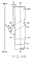
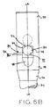
図4A,4Bを参照すると、本発明の実施例により形成された切欠き部56が、髄内釘30と関連して示される。切欠き部56が横穴48の外側開口部に隣接して設けられるとともにその外側開口部を画定する。切欠き部56はレッジ部58および逃げ部60を含む。逃げ部60は髄内釘30の長手方向軸LAに実質的に平行な方向に延在する実質的な平面を画定するとともに、横穴48の対向する前部および後部に平坦側面62,64を画定する。例えば、逃げ部60は長手方向軸LAに対して1°、2°、もしくは3°の小さい角をなしてもよく、長手方向軸LAに対して177°、178°、もしくは179°の大きい角をなしてもよい。一実施例では、平坦側面62,64は少なくとも0.2mmの幅Wを有する。少なくとも0.2mmの平坦側面62,64の幅を保証することにより、製造時に平坦側面62,64が適切に形成されることへの保証に寄与するように製造公差が設けられる。
With reference to FIGS. 4A and 4B, a notch 56 formed in accordance with an embodiment of the present invention is shown in connection with the
レッジ部58および逃げ部60が中間部66によって互いに連結されるとともに、互いに角度αで引き離される。一実施例では、中間部66は約3mmの曲率半径を有する。一実施例では、角度αは実質的に90°である。この実施例では、レッジ部58は実質的に髄内釘30の長手方向軸LAに対して垂直である。
The
一実施例では、逃げ部60は髄内釘30の長手方向軸LAに沿って移行部36を通して延び、髄内釘30の遠位部34の近位端で終端する。特にこの実施例では、逃げ部60は遠位部34の最も外側の部分と接する平面と実質的に同一平面上にあり、かつ、髄内釘30の長手方向軸LAと平行である。その他の実施例では、逃げ部60は遠位部34へと延びて、遠位部34内で終端する。それらの実施例では、逃げ部60は遠位部34の最も外側の部分と接する平面と実質的に同一平面上にないが、髄内釘30の長手方向軸LAと実質的に平行でもよい。一方、その他の実施例では、逃げ部60は移行部36内で終端する。例えば、移行部表面を参照しながら上述したように逃げ部60は移行部36表面で終端してもよい。実施例では、逃げ部60の遠位で終端する位置、すなわち逃げ部60の最も遠位の点の位置を変更するように、逃げ部60が髄内釘30の長手方向軸LAに平行な平面に維持されるとともに、髄内釘30の長手方向軸LAに近づくもしくはさらに遠ざかるように移される。
In one embodiment, the relief 60 extends through the
髄内釘30内に切欠き部56を形成することにより、厚さTを有する材料がラグスクリュー50の近位側の、逃げ部60と、ラグスクリュー50の近位に位置する髄内釘30の最も外側の表面との間に配置され、一方、ラグスクリュー50の遠位側からは対応する量の材料が除去される。ラグスクリュー50の遠位から材料を除去することにより、支持点54の遠位側の領域などの、横穴48の外側開口部にすぐ近接する材料内にもたらされる応力が、上述したように、髄内釘30の長手方向軸LAに向かう方向に分散される。その結果、横穴48の外側開口部にすぐ近接する材料内にもたらされる応力は、髄内釘30を形成する材料がより厚い肉厚を有する髄内釘30の部位、すなわち、横穴48の外側開口部にすぐ近接する材料に関して、髄内釘30の長手方向軸LAからの横方向距離が減少して隙間が空けられた髄内釘30の部位を通して分散される。これにより応力が髄内釘30の本体全体に亘って分散されるため、横穴48の外側開口部の領域における応力集中を軽減することが可能となる。
By forming a notch 56 in the
結果として、髄内釘30は公知の髄内釘に対して縮小された厚さを有する一方、公知の髄内釘に比べて実質的に同等もしくは向上された強度特性を提供する。例えば、上述したように、髄内釘30の近位部38の直径は15.5mmであるのに対し、類似の従来技術の髄内釘の近位部の直径は17mmである。同様に、髄内釘30の横穴48の直径は10.5mmであるのに対し、類似の従来技術の髄内釘における対応する横穴の直径は12mmである。
As a result, the
本発明の髄内釘30の好ましい応力分布をさらに向上させるために、平坦側面62,64が、図4Bに示し、かつ、上述したように、横穴48の外側開口部68の両側に形成される。さらに、図4A,4Bに示す実施例では、レッジ部58の最も外側の点が支持点54を画定する。その結果、切欠き部56の存在においてさえ、支持点54がその相対位置に維持される。
To further improve the preferred stress distribution of the
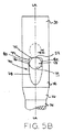
図5A,5Bを参照すると、本発明の教示にしたがって形成された切欠き部の別の実施例を切欠き部70として示す。切欠き部70は図8,9の髄内釘30とともに利用され、対応する部品を示すのに同様の参照符号が用いられる。図5A,5Bを参照すると、切欠き部70が、レッジ部72と、中間部74と、長手方向部76と、傾斜部78と、を含む。中間部74はレッジ部72を長手方向部76と接続する。一実施例では、中間部74は約3mmの曲率半径を有する。
With reference to FIGS. 5A and 5B, another embodiment of a notch formed in accordance with the teachings of the present invention is shown as a notch 70. The notch 70 is utilized with the
図5A,5Bを参照すると、長手方向部76は髄内釘30の長手方向軸LAと実質的に平行な平面に延在する実質的な平面を画定する。一実施例では、長手方向部76は、横穴48を画定する壁部の最も遠位側の部分の近傍の位置ではあるが、遠位の部分に近い位置で終端する。別の言い方をすれば、長手方向部76は横穴48の最も遠位の部分に達する手前で終端する。切欠き部70の逃げ部78と同様に、長手方向部76は横穴48の前部および後部に隣接して平坦側面80,82を画定する。一実施例では、平坦側面80,82は少なくとも0.2mmの幅Wを有する。
Referring to FIGS. 5A and 5B, the
切欠き部70の傾斜部78は、長手方向部76から遠位に延びる実質的に平坦な傾斜面を画定する。傾斜部78は髄内釘30の長手方向軸LAと角βをなす。傾斜部78は近位側方向では髄内釘30の長手方向軸LAに向かい、かつ、遠位側方向では髄内釘30の長手方向軸30から離れるように角度をなすように指向される。一実施例では、角度βは45°未満である。別の実施例では、角度βは30°未満である。実施例では、角度βは約0.0°(この場合、傾斜部78は逃げ部78を形成する)、0.5°、1°、3°、5°、10°、および、約15°、20°、25°、30°の大きさである。さらに、角度βが小さいほど、傾斜部78は髄内釘30の長手方向軸LAにより平行に近づく。その結果、製造工程時に傾斜部78の形成が簡単になり、骨成長のために確保される空間の容積が増加する。
The
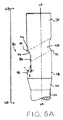
図6A,6Bを参照すると、本発明の教示にしたがって形成された切欠き部の別の実施例を切欠き部84として示す。切欠き部84は図5A,5Bの切欠き部70と実質的に同様であり、図8,9の髄内釘30とともに用いられ、同一もしくは実質的に同一の部品を表すのに同様の参照符号が用いられる。切欠き部70の長手方向部76とは対照的に、切欠き部84の長手方向部86は横穴48の最も遠位側の部分から離れた位置で終端する。別の実施例では、長手方向部86は横穴48の最も遠位側の点と一致する点で終端する。
With reference to FIGS. 6A and 6B, another embodiment of a notch formed in accordance with the teachings of the present invention is shown as notch 84. The notch 84 is substantially similar to the notch 70 of FIGS. 5A and 5B and is used with the
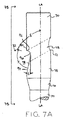
図7A,7Bを参照すると、本発明の教示にしたがって形成された切欠き部の別の実施例を切欠き部32として示す。切欠き部32は図5A,5Bの切欠き部70と実質的に同様であり、同一もしくは実質的に同一の部品を特定するのに同様の参照番号が用いられる。図7A,7Bを参照すると、図5A,5Bの切欠き部70とは異なり、髄内釘30の長手方向軸LAに平行な切欠き部32の部位はなく、切欠き部32は長手方向部76を持たない。したがって、切欠き部32のレッジ部92および傾斜部94は中間部96によって互いに接続されるとともに、角度γで互いに分離される。一実施例では、角度γは実質的に90°である。一実施例では、中間部96は約3mmの曲率半径を有する。一実施例では、レッジ部92はまた湾曲している。一実施例では、レッジ部32は約3mmの曲率半径を有する。
With reference to FIGS. 7A and 7B, another embodiment of a notch formed in accordance with the teachings of the present invention is shown as
一方、別の実施例では、レッジ部92は実質的な平面を含む。一実施例では、平面を含むレッジ部92は横穴48の長手方向軸と交差するとともに、髄内釘30の長手方向軸LAと実質的に垂直である。次に傾斜部94を参照すると、傾斜部94は、髄内釘30の長手方向軸LAから遠位方向に向かって広がるようにテーパ状となって実質的な平面98を画定し、髄内釘30の長手方向軸LAに関して角度ε(図7A)を形成する。一実施例では、角度εは9°である。別の実施例では、角度εは10°である。さらに別の実施例では、角度εは6°である。実施例では、角度εは4〜12°の範囲の角度である。
On the other hand, in another embodiment, the
一実施例では、角度γおよび角度ε(図7A)により、レッジ部92は髄内釘30の長手方向軸LAに垂直な線に関して僅かな角度を形成する。したがって、レッジ部92は実質的には長手方向軸LAと垂直なままでもよいが、髄内釘30の長手方向軸LAと角度δ(図7A)を形成してもよい。したがって、実施例では、角度δが長手方向軸LAから90°の角度をなし、レッジ部92が長手方向軸LAに垂直である代わりに、任意の特定の実施例では、角度δは、180°から角度γと角度εとの総和を差し引いた差に等しい。一例では、角度γが90°であり、角度εが10°のとき、角度δは80°である。
In one example, the angle γ and the angle ε (FIG. 7A) cause the
髄内釘30に切欠き部32,56,70,84のいずれかを形成するように、中間部66,74,96の所望の半径に実質的に等しい半径を有する切削工具を髄内釘30の長手方向軸LAに実質的に垂直な方向に向かって前進させることにより、髄内釘30に切欠き部32,56,70,84が機械加工される。一実施例では、切削工具の長手方向軸が横穴48の長手方向に垂直に揃えられる。一実施例では、機械工具の動作はコンピュータ数値制御(「CNC」)などを用いることにより、自動制御される。ひとたび機械工具が所望の深さに達すると、切削工具の髄内釘30への更なる動作、すなわち、髄内釘30の長手方向軸LAに向かう方向への動作が停止される。中間部66,74,96の曲率半径と実質的に同様の曲率半径を有する切削工具を所望の深さに進めることにより、レッジ部58,72,92および中間部66,74,96の両方が実質的に同時に形成される。
A cutting tool having a radius substantially equal to the desired radius of the intermediate portions 66, 74, 96 is formed in the
次いで、必要に応じて長手方向部76,86もしくは逃げ部60を形成するように、切削工具が髄内釘30の長手方向軸LAに実質的に平行な遠位方向に移動される。一旦、切削工具が長手方向部76,86もしくは逃げ部60の所望の遠位の終端点まで進むと、髄内釘30を形成する材料から、傾斜部78,90が形成される。一方、切欠き部32などのように、長手方向部76,86を必要としない場合、長手方向部76,86を形成するステップが省略され、レッジ部58,72,92および中間部66,74,96を形成させた後に、傾斜部もしくは逃げ部60,78,90が直接形成される。
The cutting tool is then moved in a distal direction substantially parallel to the longitudinal axis LA of the
傾斜部78,94を形成させるように、切削工具が所望の深さから遠位の方向、および髄内釘30の外側すなわち髄内釘30の長手方向軸LAから離れる方向の双方に前進する。別の言い方をすれば、長手方向軸LAに対して角度β、ε(図5A,7A)をなす平面に沿って長手方向軸LAから離れるように切削工具が前進する。このような切削工具の前進は、切削工具が髄内釘30を形成する材料と接触しなくなるまで続けられる。切削工具が髄内釘30を形成する材料と接触しなくなると、傾斜部78,94が形成される。
The cutting tool is advanced both in the direction distal from the desired depth and in the direction away from the
一方、別の実施例では、傾斜部78,94および/または長手方向部76,86を形成するように、レッジ部58,72,92、中間部66,74,96、そして一部の実施例における長手方向部76,86を形成させたのちに、髄内釘30から切削工具を取り外して、切欠き部の所望の最も遠位の位置に再び配置してもよい。切削工具をこの遠位の位置から髄内釘30内へ、すなわち、長手方向軸LAに向かう方向、および髄内釘30に関して近位側の方向の、双方へと前進させてもよい。別の言い方をすれば、長手方向軸LAに対して角度β、ε(図5A,7A)をなす平面に沿って長手方向軸LAに向かって切削工具を前進させる。切削工具が前進し続けるに従い、それに応じて傾斜部78,94の長さおよび深さが増加する。切削工具が中間部66,74,96もしくは長手方向部76,86の最も外側の点に実質的に近接し、かつ/または接触したとき、切削工具の前進は停止する。そして、まだ形成されていないとしても、切削工具を髄内釘30の長手方向軸LAに対して平行な近位方向へと進めることにより、長手方向部76,86が形成される。
On the other hand, in another embodiment,
別の実施例では、中間部96,66の所望の半径よりも大きい半径を有する切削工具を、髄内釘30の前部および後部のうちの一方から他方にかけて前進させることにより、髄内釘30に切欠き部32,56が機械加工される。特に、図7Aおよび切欠き部32を参照すると、切削工具の長手方向軸が髄内釘30の長手方向軸LAと角度εをなすように揃えられる。次いで、切削工具は、その先端がレッジ部92の所望の最も近位の点と同じ近位の位置に進められた状態で、髄内釘30の前部もしくは後部のうちの一方に配置される。そして、切削工具が髄内釘30の外側に亘って対向する前部もしくは後部へと前進し、切欠き部32のレッジ部92および傾斜部94が形成される。さらに、標準的な円筒型の切削工具を用いることにより、レッジ部92が実質的に90°に等しい角度γ(図7A)で形成される。一旦、レッジ部92および傾斜部94が形成されると、中間部96を形成するように、上述したステップのうちの一つなどの、追加の機械加工ステップが必要となる。一実施例では、機械工具の動作はコンピュータ数値制御(「CNC」)装置などを用いることにより自動制御される。有利には、中間部96,66の所望の直径よりも大きい直径を有する切削工具を用い、かつ、髄内釘30の長手方向軸LAに沿って切削工具を前進させる代わりに髄内釘30に亘って切削工具を前進させることによって切欠き部32,56を形成させることにより、切欠き部32,56の形成時に髄内釘30に生じる振動が低減される。
In another embodiment, the
その他の実施例では、切欠き部32,56,70,84は、鋳造、鍛造、もしくはその他の周知の製造技術により髄内釘30に形成される。
In other embodiments, the
本発明を好ましい設計を有するものとして記載したが、本発明は、その精神および開示の範囲内で更に修正することができる。したがって、本発明は、その一般的原則を用いる本発明のあらゆる変形例、使用、もしくは適用にまで及ぶことを意図するものである。さらに本発明は、こうした本発明からの転換が、本発明に関連して周知となりもしくは技術的に慣行となるものとして、本発明の範囲に含まれ、保護されることを意図するものである。 While this invention has been described as having a preferred design, the present invention can be further modified within the spirit and scope of the disclosure. Accordingly, the present invention is intended to cover all variations, uses, or applications of the invention using its general principles. Furthermore, the present invention is intended to be within the scope of the present invention and to be protected as such conversion from the present invention becomes well known or technically practiced in connection with the present invention.
Claims (24)
前記長尺の本体が長尺本体表面を画定し、前記長尺本体の前記近位部が、その内部を延在する横穴を画定する内部壁を有し、前記横穴は、前記長尺の本体の前記長手方向軸を横断する方向に該長尺の本体の前記外側から前記内側へと延在し、前記近位部は、前記長尺の本体の前記外側の前記横穴に近接するように配置された切欠き部を含んでおり、
前記切欠き部が、
実質的に内側方向から外側方向にかけて延在するとともに、前記横穴を画定する前記壁の最も近位側の縁部に隣接して設けられたレッジ部と、
実質的に平面を画定するとともに前記長尺の本体の前記長手方向軸と0°〜30°のランプ角を形成する傾斜部であって、該傾斜部は、前記長尺の本体の前記長手方向軸に沿って遠位方向に延在するとともに、前記長尺本体表面の遠位で終端し、かつ、前記横穴を画定する前記壁の最も遠位側の縁部から遠位側に離間した位置で終端する、傾斜部と、
前記レッジ部と、前記傾斜部と、の間に配置されるとともに、曲率半径を有する中間部と、
を備えた、髄内釘。 An intramedullary nail with an elongated body including a proximal end defined by a proximal portion, a distal end defined by a distal portion, an inner side, an outer side, and a longitudinal axis. And
The elongate body defines an elongate body surface, and the proximal portion of the elongate body has an inner wall defining a transverse hole extending therein, the transverse hole being the elongate body. Extending from the outside of the elongate body to the inside in a direction transverse to the longitudinal axis of the elongate body, the proximal portion being disposed proximate to the lateral hole on the outside of the elongate body Including a cut-out made
The notch is
A ledge portion extending substantially from the inner side to the outer side and provided adjacent to the most proximal edge of the wall defining the transverse hole;
A ramp defining a substantially planar plane and forming a ramp angle between 0 ° and 30 ° with the longitudinal axis of the elongated body, the ramp being in the longitudinal direction of the elongated body A position extending distally along the axis and terminating distally of the elongate body surface and spaced distally from the most distal edge of the wall defining the transverse hole End with an inclined part,
An intermediate portion disposed between the ledge portion and the inclined portion and having a radius of curvature;
Intramedullary nail with
前記長尺の本体の前記遠位端を画定する遠位部と、
前記遠位部から長手方向軸に沿って近位側に延びる移行部であって、近位直径を有する近位端と、遠位直径を有する遠位端と、を有しており、前記近位直径が前記遠位直径よりも大きく、かつ、移行部表面を画定する、移行部と、
前記移行部から近位側に延びるとともに、前記長尺の本体の前記近位端を画定する近位部であって、近位部表面を画定するとともに、前記移行部の前記近位直径と実質的に等しい直径を有しており、該近位部が、その内部に延在する横穴を画定する内部壁を有し、前記横穴は、前記長尺の本体の前記長手方向軸を横断する方向に該長尺本体の前記外側から前記内側へと延在し、前記長尺の本体の前記外側の前記横穴に近接するように配置された切欠き部を有しており、前記切欠き部が、前記近位部表面および前記移行部表面のうち少なくとも一方から少なくとも100mm3の体積を有する偏りを画定する、近位部と、
を備えることを特徴とする請求項1〜19のいずれかに記載の髄内釘。 An elongate body including a proximal end, a distal end, an inner side, an outer side, and a longitudinal axis, the elongate body comprising:
A distal portion defining the distal end of the elongate body;
A transition portion extending proximally from the distal portion along a longitudinal axis, the proximal portion having a proximal diameter and a distal end having a distal diameter; A transition portion having a diameter greater than the distal diameter and defining a transition surface;
A proximal portion extending proximally from the transition and defining the proximal end of the elongate body, defining a proximal surface and substantially the same as the proximal diameter of the transition The proximal portion has an inner wall defining a transverse hole extending therein, the transverse hole being transverse to the longitudinal axis of the elongate body. Extending from the outside of the elongated body to the inside, and having a notch portion disposed so as to be close to the lateral hole on the outside of the elongated body, the notch portion being A proximal portion defining a bias having a volume of at least 100 mm 3 from at least one of the proximal surface and the transition surface;
The intramedullary nail according to any one of claims 1 to 19, further comprising:
実質的に内側方向から外側方向にかけて延在するとともに、前記横穴を画定する前記壁の近位側縁部に設けられたレッジ部と、
実質的に平面を画定するとともに、前記長尺の本体の前記長手方向軸と、前記近位部表面の外側の点と接する平面と、の双方と実質的に平行な平面内に延在する逃げ部であって、前記横穴を画定する前記壁の遠位側の縁部から遠位側に離間された位置で終端する、逃げ部と、
前記レッジ部と前記逃げ部との間に配置されるとともに、曲率半径を有する中間部と、
をさらに備えることを特徴とする請求項20〜22のいずれかに記載の髄内釘。 The notch is
A ledge portion extending at a substantially inner side to an outer side and provided at a proximal edge of the wall defining the lateral hole;
A relief that extends in a plane that substantially defines a plane and that is substantially parallel to both the longitudinal axis of the elongate body and a plane that contacts a point outside the proximal surface. A relief portion terminating in a position spaced distally from a distal edge of the wall defining the transverse hole;
An intermediate portion disposed between the ledge portion and the relief portion and having a radius of curvature;
The intramedullary nail according to any one of claims 20 to 22, further comprising:
実質的に内側方向から外側方向にかけて延在するとともに、前記横穴を画定する前記壁の最も近位側の縁部に隣接して設けられたレッジ部と、
実質的に平面を画定するとともに前記長尺の本体の前記長手方向軸と0.5°〜30°のランプ角を形成する傾斜部であって、該傾斜部は、前記長尺の本体の前記長手方向軸から遠位方向に向かって広がるとともに、前記近位部表面および前記移行部表面のうちの一方の遠位で終端し、かつ、前記横穴を画定する前記壁の最も遠位側の縁部から遠位側に離間した位置で終端する、傾斜部と、
前記レッジ部と、前記傾斜部と、の間に配置されるとともに、曲率半径を有する中間部と、
をさらに備えることを特徴とする請求項20〜22のいずれかに記載の髄内釘。 The notch is
A ledge portion extending substantially from the inner side to the outer side and provided adjacent to the most proximal edge of the wall defining the transverse hole;
A ramp defining a substantially planar plane and forming a ramp angle between 0.5 ° and 30 ° with the longitudinal axis of the elongate body, the ramp being a portion of the elongate body. A distalmost edge of the wall that extends distally from the longitudinal axis and terminates distally of one of the proximal surface and the transition surface and defines the transverse hole An inclined portion that terminates at a position spaced distally from the portion; and
An intermediate portion disposed between the ledge portion and the inclined portion and having a radius of curvature;
The intramedullary nail according to any one of claims 20 to 22, further comprising:
Applications Claiming Priority (3)
| Application Number | Priority Date | Filing Date | Title |
|---|---|---|---|
| US10558308P | 2008-10-15 | 2008-10-15 | |
| US61/105,583 | 2008-10-15 | ||
| PCT/EP2009/007353 WO2010043380A1 (en) | 2008-10-15 | 2009-10-13 | Intramedullary nail |
Publications (2)
| Publication Number | Publication Date |
|---|---|
| JP2012505672A true JP2012505672A (en) | 2012-03-08 |
| JP5702290B2 JP5702290B2 (en) | 2015-04-15 |
Family
ID=41460134
Family Applications (1)
| Application Number | Title | Priority Date | Filing Date |
|---|---|---|---|
| JP2011531392A Expired - Fee Related JP5702290B2 (en) | 2008-10-15 | 2009-10-13 | Intramedullary nail |
Country Status (7)
| Country | Link |
|---|---|
| US (2) | US8668695B2 (en) |
| EP (1) | EP2349040B9 (en) |
| JP (1) | JP5702290B2 (en) |
| KR (1) | KR101631610B1 (en) |
| CN (1) | CN102176873A (en) |
| ES (1) | ES2524076T3 (en) |
| WO (1) | WO2010043380A1 (en) |
Cited By (2)
| Publication number | Priority date | Publication date | Assignee | Title |
|---|---|---|---|---|
| JP2012055463A (en) * | 2010-09-08 | 2012-03-22 | Nakashima Medical Co Ltd | Thigh bone insertion nail |
| JP2017535401A (en) * | 2014-11-25 | 2017-11-30 | スウェマック・イノヴェーション・アーベー | Intramedullary nail |
Families Citing this family (35)
| Publication number | Priority date | Publication date | Assignee | Title |
|---|---|---|---|---|
| US20030055316A1 (en) * | 2001-09-19 | 2003-03-20 | Brannon James Kevin | Endoscopic bone debridement |
| AU2006351469B2 (en) * | 2006-12-07 | 2012-10-18 | Ihip Surgical, Llc | Method and apparatus for total hip replacement |
| US8579985B2 (en) * | 2006-12-07 | 2013-11-12 | Ihip Surgical, Llc | Method and apparatus for hip replacement |
| US8974540B2 (en) | 2006-12-07 | 2015-03-10 | Ihip Surgical, Llc | Method and apparatus for attachment in a modular hip replacement or fracture fixation device |
| US8303589B2 (en) | 2008-06-24 | 2012-11-06 | Extremity Medical Llc | Fixation system, an intramedullary fixation assembly and method of use |
| US8313487B2 (en) | 2008-06-24 | 2012-11-20 | Extremity Medical Llc | Fixation system, an intramedullary fixation assembly and method of use |
| US9017329B2 (en) | 2008-06-24 | 2015-04-28 | Extremity Medical, Llc | Intramedullary fixation assembly and method of use |
| US9289220B2 (en) | 2008-06-24 | 2016-03-22 | Extremity Medical Llc | Intramedullary fixation assembly and method of use |
| US9044282B2 (en) | 2008-06-24 | 2015-06-02 | Extremity Medical Llc | Intraosseous intramedullary fixation assembly and method of use |
| US8328806B2 (en) | 2008-06-24 | 2012-12-11 | Extremity Medical, Llc | Fixation system, an intramedullary fixation assembly and method of use |
| US8668695B2 (en) | 2008-10-15 | 2014-03-11 | Zimmer Gmbh | Intramedullary nail |
| WO2011044917A1 (en) * | 2009-10-13 | 2011-04-21 | Zimmer Gmbh | An orthopedic nail and an orthopedic nail system |
| US8556896B2 (en) * | 2010-01-27 | 2013-10-15 | Zimmer, Inc. | Distal relief for a surgical device |
| EP2731553B1 (en) * | 2011-07-15 | 2022-03-23 | Smith & Nephew, Inc. | Reducing implant stress zones |
| US9427266B2 (en) | 2012-04-16 | 2016-08-30 | DePuy Synthes Products, Inc. | Bump cut on hole edge |
| EP2712562B1 (en) | 2012-10-01 | 2015-07-29 | Stryker Trauma GmbH | Intramedullary nail and implant system comprising the nail |
| EP2906248B1 (en) | 2012-10-12 | 2018-12-05 | MedImmune Limited | Pyrrolobenzodiazepines and conjugates thereof |
| HUE042731T2 (en) | 2012-10-12 | 2019-07-29 | Adc Therapeutics Sa | Pyrrolobenzodiazepine-antibody conjugates |
| BR112015008238A2 (en) | 2012-10-12 | 2017-11-28 | Adc Therapeutics Sarl | pyrrolbenzodiazepine-anti-cd22 antibody conjugates |
| SI2906253T1 (en) | 2012-10-12 | 2018-11-30 | Adc Therapeutics Sa | Pyrrolobenzodiazepine - anti-psma antibody conjugates |
| AU2013328625B2 (en) | 2012-10-12 | 2016-12-15 | Adc Therapeutics Sa | Pyrrolobenzodiazepine-antibody conjugates |
| WO2014057120A1 (en) | 2012-10-12 | 2014-04-17 | Adc Therapeutics Sàrl | Pyrrolobenzodiazepine-antibody conjugates |
| DE102013005414A1 (en) * | 2013-03-28 | 2014-10-02 | Dietmar Wolter | Osteosynthesis system for the multidirectional, angularly stable treatment of fractures of long bones including an intramedullary nail and bone screws |
| US9895177B2 (en) | 2016-01-15 | 2018-02-20 | ARTHREX, GmbH | Bone fixation device for treatment of femoral fractures |
| WO2018042595A1 (en) * | 2016-09-01 | 2018-03-08 | 株式会社オーミック | Thighbone fixing tool |
| US10492803B2 (en) | 2016-09-22 | 2019-12-03 | Globus Medical, Inc. | Systems and methods for intramedullary nail implantation |
| US11083503B2 (en) | 2016-09-22 | 2021-08-10 | Globus Medical, Inc. | Systems and methods for intramedullary nail implantation |
| US11446072B2 (en) | 2017-10-10 | 2022-09-20 | DePuy Synthes Products, Inc. | Self-retaining nail to insertion handle interface |
| EP3740145A1 (en) | 2018-01-15 | 2020-11-25 | GLW, Inc. | Hybrid intramedullary rods |
| GB201908128D0 (en) | 2019-06-07 | 2019-07-24 | Adc Therapeutics Sa | Pyrrolobenzodiazepine-antibody conjugates |
| US11633219B2 (en) | 2019-06-26 | 2023-04-25 | Globus Medical, Inc. | Fenestrated pedicle nail |
| US11285008B1 (en) * | 2019-11-08 | 2022-03-29 | Omnes Medical Inc. | Hip implant with compression resistance and self-centering features |
| KR102276643B1 (en) | 2019-11-11 | 2021-07-13 | 주식회사 제일메디칼코퍼레이션 | Leg screw for bone fixation having separate structure |
| KR102153491B1 (en) | 2020-03-31 | 2020-09-08 | 한국건설기술연구원 | Apparatus and method for estimating the sound source arrival angle |
| JP2023527085A (en) | 2020-05-29 | 2023-06-26 | ストライカー・ユーロピアン・オペレーションズ・リミテッド | Funnel hole for intramedullary nail |
Citations (5)
| Publication number | Priority date | Publication date | Assignee | Title |
|---|---|---|---|---|
| JPH09509333A (en) * | 1993-06-01 | 1997-09-22 | エンドカーレ アーゲー | Osteosynthesis aids for the treatment of subtrochanteric, peritrochanteric, and femoral neck fractures |
| JP2004237108A (en) * | 2003-02-07 | 2004-08-26 | Stryker Trauma Gmbh | Coupling nail for proximal femoral fracture |
| US20060200160A1 (en) * | 2005-02-18 | 2006-09-07 | Ebi, L.P. | Internal fixation assemblies and associated instruments |
| JP2008036094A (en) * | 2006-08-04 | 2008-02-21 | Synthes Kk | Intramedullary nail and nailing system equipped with the same |
| JP2009509660A (en) * | 2005-09-28 | 2009-03-12 | スミス アンド ネフュー インコーポレーテッド | Equipment for reducing femoral neck fractures |
Family Cites Families (160)
| Publication number | Priority date | Publication date | Assignee | Title |
|---|---|---|---|---|
| US2239088A (en) * | 1940-03-30 | 1941-04-22 | Joe J Ettinger | Fracture nail |
| US2518019A (en) * | 1946-11-29 | 1950-08-08 | Kane John Timothy | Intramedullary splint |
| US3433220A (en) * | 1966-12-30 | 1969-03-18 | Robert E Zickel | Intramedullary rod and cross-nail assembly for treating femur fractures |
| US3996931A (en) * | 1975-07-03 | 1976-12-14 | Callender Jr George R | Fractured bone setting fastener assembly |
| US4103683A (en) * | 1977-06-03 | 1978-08-01 | Neufeld John A | Sub-trochanteric nail |
| CH651192A5 (en) * | 1980-11-20 | 1985-09-13 | Synthes Ag | OSTEOSYNTHETIC DEVICE AND CORRESPONDING DRILL GAUGE. |
| CA1178150A (en) * | 1981-06-18 | 1984-11-20 | Emmanuel Anapliotis | Nail for fixing a fracture of the femur |
| US4976258A (en) * | 1983-03-09 | 1990-12-11 | Howmedica International, Inc. | Locking nail |
| CH668173A5 (en) * | 1984-05-14 | 1988-12-15 | Synthes Ag | DEVICE FOR FIXING TUBE BONE FRACTURES WITH A BONE MARBLE NAIL AND AT LEAST ONE CROSS-BOLT LOCKING. |
| CH666176A5 (en) * | 1984-11-30 | 1988-07-15 | Straumann Inst Ag | DEVICE FOR TREATING A BONE AND NAIL FOR SUCH A DEVICE. |
| US4622959A (en) * | 1985-03-05 | 1986-11-18 | Marcus Randall E | Multi-use femoral intramedullary nail |
| US4776330A (en) * | 1986-06-23 | 1988-10-11 | Pfizer Hospital Products Group, Inc. | Modular femoral fixation system |
| DE8620399U1 (en) | 1986-07-30 | 1986-10-09 | Howmedica GmbH Werk Schönkirchen, 2314 Schönkirchen | Osteosynthesis aids for the treatment of subtrochanteric fractures |
| US5312406A (en) * | 1986-12-30 | 1994-05-17 | Smith & Nephew Richards Inc. | Method of treating an intertrochanteric fracture |
| US4827917A (en) * | 1986-12-30 | 1989-05-09 | Richards Medical Company | Fermoral fracture device |
| US5167663A (en) * | 1986-12-30 | 1992-12-01 | Smith & Nephew Richards Inc. | Femoral fracture device |
| DE3729840C1 (en) | 1987-09-05 | 1989-02-02 | Dauerer Hermann Heinrich Micha | Medullary cavity - locking nail |
| US4846162A (en) * | 1987-09-14 | 1989-07-11 | Moehring H David | Orthopedic nail and method of bone fracture fixation |
| DE3734111A1 (en) * | 1987-10-06 | 1989-04-20 | Mecron Med Prod Gmbh | INTERMEDIATE NAIL FOR TREATMENT OF BONE BREAKS ACCORDING TO THE PRINCIPLE OF MARBLE NAILING AND MARNEL TOOL |
| US4805607A (en) * | 1987-12-03 | 1989-02-21 | Boehringer Mannheim Corporation | Modular intramedullary nail system |
| US5176681A (en) * | 1987-12-14 | 1993-01-05 | Howmedica International Inc. | Intramedullary intertrochanteric fracture fixation appliance and fitting device |
| US4875474A (en) * | 1988-01-29 | 1989-10-24 | Biomet, Inc. | Variable wall thickness interlocking intramedullary nail |
| CH674613A5 (en) * | 1988-03-14 | 1990-06-29 | Synthes Ag | |
| US4895572A (en) * | 1988-11-25 | 1990-01-23 | Ira Chernoff | Interlocking femoral prosthesis device |
| DE3840798A1 (en) * | 1988-12-01 | 1990-06-21 | Mecron Med Prod Gmbh | MARKING NAIL |
| US5066296A (en) * | 1989-02-02 | 1991-11-19 | Pfizer Hopsital Products Group, Inc. | Apparatus for treating a fracture |
| US5034013A (en) * | 1989-04-24 | 1991-07-23 | Zimmer Inc. | Intramedullary nail |
| US4978349A (en) * | 1989-08-03 | 1990-12-18 | Synthes (U.S.A.) | Fixation plate |
| US5032125A (en) * | 1990-02-06 | 1991-07-16 | Smith & Nephew Richards Inc. | Intramedullary hip screw |
| US5112333A (en) * | 1990-02-07 | 1992-05-12 | Fixel Irving E | Intramedullary nail |
| US5057103A (en) * | 1990-05-01 | 1991-10-15 | Davis Emsley A | Compressive intramedullary nail |
| US5122141A (en) * | 1990-08-30 | 1992-06-16 | Zimmer, Inc. | Modular intramedullary nail |
| FR2668360B1 (en) | 1990-10-25 | 1993-02-19 | Armor | DEVICE FOR OSTEOSYNTHESIS OF A HIGH OR STAGEED FRACTURE OF THE FEMUR. |
| GB9111826D0 (en) | 1991-06-01 | 1991-07-24 | Halder Subhash C Dr | Improvements in or relating to bone support |
| DE9109883U1 (en) * | 1991-08-09 | 1991-09-26 | Howmedica Gmbh, 2314 Schoenkirchen, De | |
| DE9115201U1 (en) * | 1991-12-07 | 1992-02-06 | Howmedica Gmbh, 2314 Schoenkirchen, De | |
| US5356410A (en) * | 1991-12-13 | 1994-10-18 | Dietmar Pennig | Adjuvant for osteosynthesis in the case of pertrochanteric fracture of the neck of the femur |
| FR2698261B1 (en) * | 1992-11-24 | 1995-03-17 | Lacaffiniere Jean Yves De | Device for guiding a double screw of the neck of the femur for locked trochantero-diaphyseal nail. |
| US5429640A (en) * | 1992-11-27 | 1995-07-04 | Clemson University | Intramedullary rod for fracture fixation of femoral shaft independent of ipsilateral femoral neck fracture fixation |
| AU2940092A (en) * | 1992-12-04 | 1994-07-04 | Synthes Ag, Chur | Modular marrow nail |
| US5499986A (en) * | 1994-01-07 | 1996-03-19 | Smith & Nephew Richards Inc. | Quick release handle apparatus for removing and inserting intramedullary nails |
| ATE188363T1 (en) * | 1994-02-21 | 2000-01-15 | Collux Ab | IMPLANT FOR THE TREATMENT OF FRACTURES OF THE FEMUR |
| US5620445A (en) * | 1994-07-15 | 1997-04-15 | Brosnahan; Robert | Modular intramedullary nail |
| US5855579A (en) * | 1994-07-15 | 1999-01-05 | Smith & Nephew, Inc. | Cannulated modular intramedullary nail |
| US5489284A (en) * | 1994-07-15 | 1996-02-06 | Smith & Nephew Richards Inc. | Cannulated modular intramedullary nail |
| US5549610A (en) * | 1994-10-31 | 1996-08-27 | Smith & Nephew Richards Inc. | Femoral intramedullary nail |
| US5578035A (en) * | 1995-05-16 | 1996-11-26 | Lin; Chih-I | Expandable bone marrow cavity fixation device |
| IT1275300B (en) * | 1995-06-05 | 1997-08-05 | Gruppo Ind Bioimpianti Srl | BLOCKED ENDOMIDOLLAR NAIL SUITABLE FOR FEMORE FRACTURES IN PARTICULAR |
| US5766174A (en) * | 1995-09-26 | 1998-06-16 | Orthologic Corporation | Intramedullary bone fixation device |
| DE19544750A1 (en) * | 1995-11-30 | 1997-06-05 | Christoph Rehberg | Implantable device with internal electrode to promote tissue growth |
| US5658339A (en) * | 1996-01-05 | 1997-08-19 | Wright Medical Technology, Inc. | Compression hip screw plate |
| US5779704A (en) * | 1996-03-19 | 1998-07-14 | Kim; Andrew C. | Bi-directional universal dynamic compression device |
| US5658288A (en) * | 1996-03-19 | 1997-08-19 | Kim; Andrew C. | Universal dynamic compression device for intramedullary system |
| ES2183018T3 (en) * | 1996-12-02 | 2003-03-16 | Synthes Ag | FLAT INTRAMEDULAR KEY. |
| US6106528A (en) * | 1997-02-11 | 2000-08-22 | Orthomatrix, Inc. | Modular intramedullary fixation system and insertion instrumentation |
| US6228086B1 (en) * | 1997-03-19 | 2001-05-08 | Stryker Trauma-Selzach Ag | Modular intramedullary nail |
| US5810821A (en) * | 1997-03-28 | 1998-09-22 | Biomet Inc. | Bone fixation screw system |
| JP4126091B2 (en) * | 1997-10-20 | 2008-07-30 | ジンテーズ ゲゼルシャフト ミト ベシュレンクテル ハフツング | Bone fixation device |
| AU729213B2 (en) | 1998-03-05 | 2001-01-25 | Synthes Gmbh | Medullar pin with locking opening |
| CN2362450Y (en) | 1998-06-02 | 2000-02-09 | 潘滔 | Femur neck axial controlled inner bone marrow locking nail |
| EP0976365A1 (en) | 1998-07-27 | 2000-02-02 | Osteo Ag | Tibia nail for retrograde insertion |
| JP2973316B1 (en) | 1998-08-05 | 1999-11-08 | 洋司 村嶋 | Fixing structure of lag screw used for nail for implant |
| US6010506A (en) * | 1998-09-14 | 2000-01-04 | Smith & Nephew, Inc. | Intramedullary nail hybrid bow |
| US6261289B1 (en) | 1998-10-26 | 2001-07-17 | Mark Levy | Expandable orthopedic device |
| DE19858889B4 (en) * | 1998-12-19 | 2008-08-07 | Wolter, Dietmar, Prof. Dr.Med. | Fixation system for bones |
| US6019761A (en) * | 1998-12-23 | 2000-02-01 | Gustilo; Ramon B. | Intramedullary nail and method of use |
| US6123708A (en) * | 1999-02-03 | 2000-09-26 | Pioneer Laboratories, Inc. | Intramedullary bone fixation rod |
| US6296645B1 (en) * | 1999-04-09 | 2001-10-02 | Depuy Orthopaedics, Inc. | Intramedullary nail with non-metal spacers |
| DE50015249D1 (en) * | 1999-05-12 | 2008-08-21 | Zimmer Gmbh | Locking nail for the treatment of femoral stem fractures |
| US7008425B2 (en) * | 1999-05-27 | 2006-03-07 | Jonathan Phillips | Pediatric intramedullary nail and method |
| US6221074B1 (en) * | 1999-06-10 | 2001-04-24 | Orthodyne, Inc. | Femoral intramedullary rod system |
| US7018380B2 (en) * | 1999-06-10 | 2006-03-28 | Cole J Dean | Femoral intramedullary rod system |
| ES2263442T3 (en) | 1999-08-30 | 2006-12-16 | Zimmer Gmbh | MEDULAR KEY FOR HUMER. |
| US6926719B2 (en) | 1999-10-21 | 2005-08-09 | Gary W. Sohngen | Modular intramedullary nail |
| CA2396385C (en) * | 1999-12-03 | 2007-10-30 | Synthes (U.S.A.) | Intramedullary nail |
| US20040153073A1 (en) | 2000-02-01 | 2004-08-05 | Hand Innovations, Inc. | Orthopedic fixation system including plate element with threaded holes having divergent axes |
| US6706046B2 (en) | 2000-02-01 | 2004-03-16 | Hand Innovations, Inc. | Intramedullary fixation device for metaphyseal long bone fractures and methods of using the same |
| US6235031B1 (en) * | 2000-02-04 | 2001-05-22 | Encore Medical Corporation | Intramedullary fracture fixation device |
| US6808527B2 (en) * | 2000-04-10 | 2004-10-26 | Depuy Orthopaedics, Inc. | Intramedullary nail with snap-in window insert |
| US6210414B1 (en) * | 2000-04-20 | 2001-04-03 | Chin Lin | Bone fastener for shinbone and thighbone |
| US7963966B2 (en) | 2000-06-06 | 2011-06-21 | Cole J Dean | Bone fixation system and method of use |
| JP4278289B2 (en) * | 2000-07-27 | 2009-06-10 | 有限会社ケイオーアイ | Intramedullary nail |
| US6579293B1 (en) | 2000-08-02 | 2003-06-17 | Rama E. Chandran | Intramedullary rod with interlocking oblique screw for tibio-calcaneal arthrodesis |
| US6527775B1 (en) | 2000-09-22 | 2003-03-04 | Piper Medical, Inc. | Intramedullary interlocking fixation device for the distal radius |
| RS49794B (en) | 2000-11-22 | 2008-06-05 | Milorad Mitković | Internal fixator of bones |
| CN2471292Y (en) | 2001-01-11 | 2002-01-16 | 万黎 | Automatic pressurized anti-rotation intramedullary nail |
| GB0102141D0 (en) | 2001-01-27 | 2001-03-14 | Davies John B C | Improvements in or relating to expandable bone nails |
| DE20101917U1 (en) * | 2001-02-03 | 2002-06-06 | Stryker Trauma Gmbh | Osteosynthesis aids made of a steel, cobalt and / or titanium alloy |
| US7066943B2 (en) | 2001-03-30 | 2006-06-27 | Zirkle Jr Lewis G | Method and apparatus for locating and stabilizing an orthopedic implant |
| US20020151897A1 (en) * | 2001-03-30 | 2002-10-17 | Zirkle Lewis G. | Method and apparatus for locating and stabilizing an orthopedic implant |
| US6818006B2 (en) | 2001-04-03 | 2004-11-16 | Medtronic Vascular, Inc. | Temporary intraluminal filter guidewire |
| DE20105775U1 (en) | 2001-04-03 | 2001-06-07 | Joos Martin | Bone nail for surgical purposes |
| US6443954B1 (en) * | 2001-04-24 | 2002-09-03 | Dale G. Bramlet | Femoral nail intramedullary system |
| US6648889B2 (en) * | 2001-04-24 | 2003-11-18 | Dale G. Bramlet | Intramedullary hip nail with bifurcated lock |
| US6488684B2 (en) * | 2001-04-25 | 2002-12-03 | Dale G. Bramlet | Intramedullary nail |
| US6652528B2 (en) * | 2001-07-17 | 2003-11-25 | Biomet, Inc. | Intramedullary nail with modular sleeve |
| US20030069581A1 (en) * | 2001-10-04 | 2003-04-10 | Stinson David T. | Universal intramedullary nails, systems and methods of use thereof |
| WO2003030749A1 (en) | 2001-10-12 | 2003-04-17 | Flores Davila Jorge P | Grooved centro-medullary nail and a method for the osteosynthesis of diaphyseal segments |
| US6835197B2 (en) | 2001-10-17 | 2004-12-28 | Christoph Andreas Roth | Bone fixation system |
| IL147783A0 (en) | 2002-01-23 | 2002-08-14 | Disc O Tech Medical Tech Ltd | Locking mechanism for intramedulliary nails |
| US7247171B2 (en) | 2002-03-11 | 2007-07-24 | Sotereanos Nicholas G | Modular hip implants |
| DE20204655U1 (en) | 2002-03-21 | 2002-06-13 | Stryker Trauma Gmbh | Locking nail and target device |
| US6981976B1 (en) | 2002-05-13 | 2006-01-03 | Biomet, Inc. | Method and apparatus for inserting and countersinking a modular screw |
| US20060161156A1 (en) | 2002-05-30 | 2006-07-20 | Orbay Jorge L | Fracture fixation device |
| US20060149257A1 (en) | 2002-05-30 | 2006-07-06 | Orbay Jorge L | Fracture fixation device |
| FR2841460B1 (en) | 2002-06-28 | 2005-04-01 | Sanortho | EPIPHYSARY OSTEOSYNTHESIS SCREW IN TWO PARTS, IN PARTICULAR FOR NAILS OR PLATES, AND OSTEOSYNTHESIS DEVICE INCORPORATING IT |
| US7001386B2 (en) | 2002-07-23 | 2006-02-21 | Advanced Orthopaedic Solutions, Inc. | Intramedullary nail for long bone fractures |
| MXPA05003270A (en) | 2002-09-27 | 2005-10-18 | Synthes Ag | Intramedullary nail. |
| AU2002328245A1 (en) | 2002-10-03 | 2004-04-23 | Synthes Ag Chur | Device for bone fixation |
| CN100411595C (en) | 2002-10-29 | 2008-08-20 | 斯恩蒂斯有限公司 | Device for the treatment of fractures of the femur |
| US7780664B2 (en) | 2002-12-10 | 2010-08-24 | Depuy Products, Inc. | Endosteal nail |
| EP1606809A1 (en) | 2003-03-18 | 2005-12-21 | Koninklijke Philips Electronics N.V. | Smooth heat sink or reflector layer for optical record carrier |
| ATE477757T1 (en) | 2003-03-21 | 2010-09-15 | Synthes Gmbh | INTRAMEDULLARY NAIL |
| US20050075637A1 (en) | 2003-04-04 | 2005-04-07 | Semet Elliot Charles | Interlocking IM nails with outer screw |
| NZ543421A (en) | 2003-04-09 | 2008-10-31 | Synthes Gmbh | Intramedullary nail for femur fracture fixation |
| DE10320855B4 (en) | 2003-05-09 | 2008-08-14 | Aesculap Ag & Co. Kg | Implant with a threaded hole for a bone screw |
| JP4602338B2 (en) | 2003-05-17 | 2010-12-22 | デピュー インターナショナル リミテッド | Intramedullary nail assembly |
| WO2004110290A1 (en) | 2003-06-12 | 2004-12-23 | Synthes Ag Chur | Surgical nail |
| EP1631206B1 (en) | 2003-06-12 | 2007-10-10 | Synthes GmbH | Surgical nail |
| DE20309399U1 (en) | 2003-06-18 | 2003-08-28 | Stryker Trauma Gmbh | Bone nail, especially proximal femoral nail |
| US7455673B2 (en) | 2003-07-08 | 2008-11-25 | Yechiel Gotfried | Intramedullary nail system and method for fixation of a fractured bone |
| CA2534175C (en) | 2003-07-30 | 2012-01-10 | Synthes (U.S.A.) | Surgical nail |
| ATE418924T1 (en) | 2003-08-29 | 2009-01-15 | Synthes Gmbh | INTEGRAL NAIL |
| US7799030B2 (en) | 2003-09-08 | 2010-09-21 | Smith & Nephew, Inc. | Orthopaedic plate and screw assembly |
| US20050055024A1 (en) | 2003-09-08 | 2005-03-10 | James Anthony H. | Orthopaedic implant and screw assembly |
| CN100393287C (en) | 2003-09-18 | 2008-06-11 | 斯恩蒂斯有限公司 | Device for treating femoral fractures |
| DE20314742U1 (en) | 2003-09-24 | 2003-12-04 | Stryker Trauma Gmbh | Aiming device for a locking nail and locking nail |
| KR101136221B1 (en) | 2003-10-21 | 2012-04-17 | 신세스 게엠바하 | Intramedullary pin for the tibia |
| US6932818B2 (en) | 2003-10-30 | 2005-08-23 | Alfred F. Behrens | Intramedullary nail-based bone fracture treatment |
| CN1886097B (en) | 2003-12-19 | 2010-04-28 | 斯恩蒂斯有限公司 | Intramedullary nail |
| US7601153B2 (en) | 2003-12-25 | 2009-10-13 | Homs Engineering Inc. | Intramedullary nail |
| CN1909848B (en) | 2004-01-16 | 2012-05-23 | 扩展整形外科公司 | Bone fracture treatment devices |
| US7947043B2 (en) * | 2004-01-20 | 2011-05-24 | Depuy Products, Inc. | Intramedullary nail and associated method |
| US8092454B2 (en) | 2004-03-11 | 2012-01-10 | Sohngen Gary W | Fixation instrument for treating a bone fracture |
| US7771428B2 (en) | 2004-06-11 | 2010-08-10 | Synthes Usa, Llc | Intramedullary rod with spiraling flutes |
| US20060015101A1 (en) | 2004-07-15 | 2006-01-19 | Wright Medical Technology, Inc. | Intramedullary fixation assembly and devices and methods for installing the same |
| DK1639953T3 (en) | 2004-09-27 | 2008-09-29 | Orthofix Srl | Endomedullary stitch for the treatment of proximal femur fractures |
| US8435238B2 (en) | 2004-10-05 | 2013-05-07 | Michigan State University | Devices and methods for interlocking surgical screws and nails |
| US20060106389A1 (en) | 2004-11-12 | 2006-05-18 | Reber Erik W | Anti-migration threaded fastener |
| FR2881340B1 (en) | 2005-02-01 | 2008-01-11 | Tornier Sas | HUMERAL NUTS |
| US7232442B2 (en) * | 2005-02-22 | 2007-06-19 | Advanced Orthopaedic Solutions | Humeral nail |
| WO2006105673A1 (en) | 2005-04-06 | 2006-10-12 | Synthes Ag Chur | Aiming device |
| WO2007009123A2 (en) | 2005-07-14 | 2007-01-18 | Stout Medical Group, L.P. | Implant systems and methods for use |
| DE102005039854B4 (en) | 2005-08-23 | 2007-07-12 | Königsee Implantate und Instrumente zur Osteosynthese GmbH | Proximal femoral nail |
| US20070049940A1 (en) | 2005-08-31 | 2007-03-01 | Wallace Matthew S | Intramedullary nail assembly with fixed securement and associated method |
| US20070049939A1 (en) | 2005-08-31 | 2007-03-01 | Wallace Matthew S | Intramedullary nail assembly with sleeve and screw for use therewith |
| US20070049938A1 (en) | 2005-08-31 | 2007-03-01 | Wallace Matthew S | Intramedullary nail assembly with locking component, locking component and nail for use therewith |
| US7785326B2 (en) | 2005-10-14 | 2010-08-31 | Green Daniel W | System for intramedullary rod fixation and method therefor |
| US20070123876A1 (en) | 2005-10-31 | 2007-05-31 | Czartoski Timothy J | Multiple purpose nail, nail assembly and associated method |
| US20070233104A1 (en) | 2006-03-31 | 2007-10-04 | Metzinger Anthony J | Intramedullary nail implant assembly, kit and method |
| US20080119856A1 (en) | 2006-11-20 | 2008-05-22 | Yechiel Gotfried | Intramedullary nail system and method for fixation of a fractured bone |
| US7763023B2 (en) | 2007-02-09 | 2010-07-27 | Yechiel Gotfried | Intramedullary nail system and method for fixation of a fractured bone |
| FR2913876B1 (en) * | 2007-03-20 | 2009-06-05 | Memometal Technologies Soc Par | OSTEOSYNTHESIS DEVICE |
| AU2008256740A1 (en) * | 2007-05-25 | 2008-12-04 | Zimmer, Gmbh | Reinforced intramedullary nail |
| BRPI0813156A2 (en) * | 2007-06-22 | 2014-12-23 | Anthem Orthopaedics Van Llc | INTRAMEDULAR STEM WITH PIVOT HOLDER AND METHOD FOR USE |
| US8157803B1 (en) * | 2007-08-21 | 2012-04-17 | Surgical Implant Generation Network | Bone fixation using an intramedullary nail interlocked with a buttress member |
| US8668695B2 (en) | 2008-10-15 | 2014-03-11 | Zimmer Gmbh | Intramedullary nail |
| JP5237136B2 (en) | 2009-01-23 | 2013-07-17 | 中電プラント株式会社 | Transformer coil extraction jig |
| USD638126S1 (en) | 2010-04-13 | 2011-05-17 | Zimmer, Gmbh | Intramedullary nail |
| USD638125S1 (en) | 2010-04-13 | 2011-05-17 | Zimmer, Gmbh | Intramedullary nail |
-
2009
- 2009-10-13 US US12/578,038 patent/US8668695B2/en active Active
- 2009-10-13 ES ES09740851.2T patent/ES2524076T3/en active Active
- 2009-10-13 JP JP2011531392A patent/JP5702290B2/en not_active Expired - Fee Related
- 2009-10-13 EP EP09740851.2A patent/EP2349040B9/en not_active Not-in-force
- 2009-10-13 CN CN2009801405110A patent/CN102176873A/en active Pending
- 2009-10-13 WO PCT/EP2009/007353 patent/WO2010043380A1/en active Application Filing
- 2009-10-13 KR KR1020117008644A patent/KR101631610B1/en active IP Right Grant
-
2014
- 2014-01-20 US US14/158,946 patent/US9474557B2/en active Active
Patent Citations (5)
| Publication number | Priority date | Publication date | Assignee | Title |
|---|---|---|---|---|
| JPH09509333A (en) * | 1993-06-01 | 1997-09-22 | エンドカーレ アーゲー | Osteosynthesis aids for the treatment of subtrochanteric, peritrochanteric, and femoral neck fractures |
| JP2004237108A (en) * | 2003-02-07 | 2004-08-26 | Stryker Trauma Gmbh | Coupling nail for proximal femoral fracture |
| US20060200160A1 (en) * | 2005-02-18 | 2006-09-07 | Ebi, L.P. | Internal fixation assemblies and associated instruments |
| JP2009509660A (en) * | 2005-09-28 | 2009-03-12 | スミス アンド ネフュー インコーポレーテッド | Equipment for reducing femoral neck fractures |
| JP2008036094A (en) * | 2006-08-04 | 2008-02-21 | Synthes Kk | Intramedullary nail and nailing system equipped with the same |
Cited By (2)
| Publication number | Priority date | Publication date | Assignee | Title |
|---|---|---|---|---|
| JP2012055463A (en) * | 2010-09-08 | 2012-03-22 | Nakashima Medical Co Ltd | Thigh bone insertion nail |
| JP2017535401A (en) * | 2014-11-25 | 2017-11-30 | スウェマック・イノヴェーション・アーベー | Intramedullary nail |
Also Published As
| Publication number | Publication date |
|---|---|
| EP2349040A1 (en) | 2011-08-03 |
| JP5702290B2 (en) | 2015-04-15 |
| EP2349040B1 (en) | 2014-08-20 |
| KR101631610B1 (en) | 2016-06-17 |
| ES2524076T3 (en) | 2014-12-04 |
| US8668695B2 (en) | 2014-03-11 |
| US20140135767A1 (en) | 2014-05-15 |
| EP2349040B9 (en) | 2014-12-17 |
| US20100174284A1 (en) | 2010-07-08 |
| US9474557B2 (en) | 2016-10-25 |
| WO2010043380A8 (en) | 2011-05-19 |
| CN102176873A (en) | 2011-09-07 |
| KR20110084187A (en) | 2011-07-21 |
| WO2010043380A1 (en) | 2010-04-22 |
Similar Documents
| Publication | Publication Date | Title |
|---|---|---|
| JP5702290B2 (en) | Intramedullary nail | |
| US9597129B2 (en) | Reinforced intramedullary nail | |
| US8632543B2 (en) | Composite intramedullary nail | |
| JP3009232B2 (en) | Hip intramedullary screw | |
| US9974580B2 (en) | Hammertoe implant with asymmetrical head | |
| US9532818B2 (en) | Orthopedic nail and an orthopedic nail system | |
| US8252061B2 (en) | Femoral stem for artificial hip joint and artificial hip joint including the same | |
| JPH01277551A (en) | Tibia marrow nail for treatment of leg bone fracture | |
| JP2001520071A (en) | Bone fixation device | |
| EP1865865B1 (en) | Surgical fixation pin | |
| JP2008036094A (en) | Intramedullary nail and nailing system equipped with the same | |
| US11583328B2 (en) | Femoral nail and instrumentation system | |
| US20220338907A1 (en) | Surgical system for osteosynthesis of femoral fractures | |
| EP4268742A1 (en) | Internal brace plate | |
| US20230338066A1 (en) | Retrograde femoral intramedullary nail, and related systems and methods | |
| EP2473127B1 (en) | An orthopedic nail and an orthopedic nail system |
Legal Events
| Date | Code | Title | Description |
|---|---|---|---|
| A621 | Written request for application examination |
Free format text: JAPANESE INTERMEDIATE CODE: A621 Effective date: 20120508 |
|
| RD02 | Notification of acceptance of power of attorney |
Free format text: JAPANESE INTERMEDIATE CODE: A7422 Effective date: 20120823 |
|
| RD03 | Notification of appointment of power of attorney |
Free format text: JAPANESE INTERMEDIATE CODE: A7423 Effective date: 20120823 |
|
| RD04 | Notification of resignation of power of attorney |
Free format text: JAPANESE INTERMEDIATE CODE: A7424 Effective date: 20120907 |
|
| A977 | Report on retrieval |
Free format text: JAPANESE INTERMEDIATE CODE: A971007 Effective date: 20130703 |
|
| A131 | Notification of reasons for refusal |
Free format text: JAPANESE INTERMEDIATE CODE: A131 Effective date: 20130709 |
|
| A601 | Written request for extension of time |
Free format text: JAPANESE INTERMEDIATE CODE: A601 Effective date: 20131008 |
|
| A602 | Written permission of extension of time |
Free format text: JAPANESE INTERMEDIATE CODE: A602 Effective date: 20131016 |
|
| A521 | Request for written amendment filed |
Free format text: JAPANESE INTERMEDIATE CODE: A523 Effective date: 20131213 |
|
| A521 | Request for written amendment filed |
Free format text: JAPANESE INTERMEDIATE CODE: A523 Effective date: 20140108 |
|
| A131 | Notification of reasons for refusal |
Free format text: JAPANESE INTERMEDIATE CODE: A131 Effective date: 20140513 |
|
| A521 | Request for written amendment filed |
Free format text: JAPANESE INTERMEDIATE CODE: A523 Effective date: 20140813 |
|
| TRDD | Decision of grant or rejection written | ||
| A01 | Written decision to grant a patent or to grant a registration (utility model) |
Free format text: JAPANESE INTERMEDIATE CODE: A01 Effective date: 20150120 |
|
| A61 | First payment of annual fees (during grant procedure) |
Free format text: JAPANESE INTERMEDIATE CODE: A61 Effective date: 20150219 |
|
| R150 | Certificate of patent or registration of utility model |
Ref document number: 5702290 Country of ref document: JP Free format text: JAPANESE INTERMEDIATE CODE: R150 |
|
| R250 | Receipt of annual fees |
Free format text: JAPANESE INTERMEDIATE CODE: R250 |
|
| R250 | Receipt of annual fees |
Free format text: JAPANESE INTERMEDIATE CODE: R250 |
|
| R250 | Receipt of annual fees |
Free format text: JAPANESE INTERMEDIATE CODE: R250 |
|
| R250 | Receipt of annual fees |
Free format text: JAPANESE INTERMEDIATE CODE: R250 |
|
| R250 | Receipt of annual fees |
Free format text: JAPANESE INTERMEDIATE CODE: R250 |
|
| LAPS | Cancellation because of no payment of annual fees |