JP2012505108A - Shock absorbing mechanism for vehicle and aircraft seats with foot protection function - Google Patents
Shock absorbing mechanism for vehicle and aircraft seats with foot protection function Download PDFInfo
- Publication number
- JP2012505108A JP2012505108A JP2011530628A JP2011530628A JP2012505108A JP 2012505108 A JP2012505108 A JP 2012505108A JP 2011530628 A JP2011530628 A JP 2011530628A JP 2011530628 A JP2011530628 A JP 2011530628A JP 2012505108 A JP2012505108 A JP 2012505108A
- Authority
- JP
- Japan
- Prior art keywords
- spiral
- impact
- vehicle
- attachment means
- ribbons
- Prior art date
- Legal status (The legal status is an assumption and is not a legal conclusion. Google has not performed a legal analysis and makes no representation as to the accuracy of the status listed.)
- Pending
Links
Images


Classifications
-
- F—MECHANICAL ENGINEERING; LIGHTING; HEATING; WEAPONS; BLASTING
- F16—ENGINEERING ELEMENTS AND UNITS; GENERAL MEASURES FOR PRODUCING AND MAINTAINING EFFECTIVE FUNCTIONING OF MACHINES OR INSTALLATIONS; THERMAL INSULATION IN GENERAL
- F16F—SPRINGS; SHOCK-ABSORBERS; MEANS FOR DAMPING VIBRATION
- F16F1/00—Springs
- F16F1/02—Springs made of steel or other material having low internal friction; Wound, torsion, leaf, cup, ring or the like springs, the material of the spring not being relevant
- F16F1/04—Wound springs
- F16F1/06—Wound springs with turns lying in cylindrical surfaces
-
- B—PERFORMING OPERATIONS; TRANSPORTING
- B60—VEHICLES IN GENERAL
- B60N—SEATS SPECIALLY ADAPTED FOR VEHICLES; VEHICLE PASSENGER ACCOMMODATION NOT OTHERWISE PROVIDED FOR
- B60N2/00—Seats specially adapted for vehicles; Arrangement or mounting of seats in vehicles
- B60N2/24—Seats specially adapted for vehicles; Arrangement or mounting of seats in vehicles for particular purposes or particular vehicles
- B60N2/42—Seats specially adapted for vehicles; Arrangement or mounting of seats in vehicles for particular purposes or particular vehicles the seat constructed to protect the occupant from the effect of abnormal g-forces, e.g. crash or safety seats
- B60N2/4207—Seats specially adapted for vehicles; Arrangement or mounting of seats in vehicles for particular purposes or particular vehicles the seat constructed to protect the occupant from the effect of abnormal g-forces, e.g. crash or safety seats characterised by the direction of the g-forces
- B60N2/4242—Seats specially adapted for vehicles; Arrangement or mounting of seats in vehicles for particular purposes or particular vehicles the seat constructed to protect the occupant from the effect of abnormal g-forces, e.g. crash or safety seats characterised by the direction of the g-forces vertical
-
- B—PERFORMING OPERATIONS; TRANSPORTING
- B60—VEHICLES IN GENERAL
- B60N—SEATS SPECIALLY ADAPTED FOR VEHICLES; VEHICLE PASSENGER ACCOMMODATION NOT OTHERWISE PROVIDED FOR
- B60N2/00—Seats specially adapted for vehicles; Arrangement or mounting of seats in vehicles
- B60N2/02—Seats specially adapted for vehicles; Arrangement or mounting of seats in vehicles the seat or part thereof being movable, e.g. adjustable
- B60N2/04—Seats specially adapted for vehicles; Arrangement or mounting of seats in vehicles the seat or part thereof being movable, e.g. adjustable the whole seat being movable
- B60N2/16—Seats specially adapted for vehicles; Arrangement or mounting of seats in vehicles the seat or part thereof being movable, e.g. adjustable the whole seat being movable height-adjustable
-
- B—PERFORMING OPERATIONS; TRANSPORTING
- B60—VEHICLES IN GENERAL
- B60N—SEATS SPECIALLY ADAPTED FOR VEHICLES; VEHICLE PASSENGER ACCOMMODATION NOT OTHERWISE PROVIDED FOR
- B60N2/00—Seats specially adapted for vehicles; Arrangement or mounting of seats in vehicles
- B60N2/24—Seats specially adapted for vehicles; Arrangement or mounting of seats in vehicles for particular purposes or particular vehicles
- B60N2/42—Seats specially adapted for vehicles; Arrangement or mounting of seats in vehicles for particular purposes or particular vehicles the seat constructed to protect the occupant from the effect of abnormal g-forces, e.g. crash or safety seats
- B60N2/427—Seats or parts thereof displaced during a crash
- B60N2/42709—Seats or parts thereof displaced during a crash involving residual deformation or fracture of the structure
-
- B—PERFORMING OPERATIONS; TRANSPORTING
- B64—AIRCRAFT; AVIATION; COSMONAUTICS
- B64D—EQUIPMENT FOR FITTING IN OR TO AIRCRAFT; FLIGHT SUITS; PARACHUTES; ARRANGEMENTS OR MOUNTING OF POWER PLANTS OR PROPULSION TRANSMISSIONS IN AIRCRAFT
- B64D11/00—Passenger or crew accommodation; Flight-deck installations not otherwise provided for
- B64D11/06—Arrangements of seats, or adaptations or details specially adapted for aircraft seats
- B64D11/0619—Arrangements of seats, or adaptations or details specially adapted for aircraft seats with energy absorbing means specially adapted for mitigating impact loads for passenger seats, e.g. at a crash
-
- B—PERFORMING OPERATIONS; TRANSPORTING
- B64—AIRCRAFT; AVIATION; COSMONAUTICS
- B64D—EQUIPMENT FOR FITTING IN OR TO AIRCRAFT; FLIGHT SUITS; PARACHUTES; ARRANGEMENTS OR MOUNTING OF POWER PLANTS OR PROPULSION TRANSMISSIONS IN AIRCRAFT
- B64D11/00—Passenger or crew accommodation; Flight-deck installations not otherwise provided for
- B64D11/06—Arrangements of seats, or adaptations or details specially adapted for aircraft seats
- B64D11/0689—Arrangements of seats, or adaptations or details specially adapted for aircraft seats specially adapted for pilots
-
- F—MECHANICAL ENGINEERING; LIGHTING; HEATING; WEAPONS; BLASTING
- F16—ENGINEERING ELEMENTS AND UNITS; GENERAL MEASURES FOR PRODUCING AND MAINTAINING EFFECTIVE FUNCTIONING OF MACHINES OR INSTALLATIONS; THERMAL INSULATION IN GENERAL
- F16F—SPRINGS; SHOCK-ABSORBERS; MEANS FOR DAMPING VIBRATION
- F16F7/00—Vibration-dampers; Shock-absorbers
- F16F7/12—Vibration-dampers; Shock-absorbers using plastic deformation of members
- F16F7/128—Vibration-dampers; Shock-absorbers using plastic deformation of members characterised by the members, e.g. a flat strap, yielding through stretching, pulling apart
-
- Y—GENERAL TAGGING OF NEW TECHNOLOGICAL DEVELOPMENTS; GENERAL TAGGING OF CROSS-SECTIONAL TECHNOLOGIES SPANNING OVER SEVERAL SECTIONS OF THE IPC; TECHNICAL SUBJECTS COVERED BY FORMER USPC CROSS-REFERENCE ART COLLECTIONS [XRACs] AND DIGESTS
- Y10—TECHNICAL SUBJECTS COVERED BY FORMER USPC
- Y10T—TECHNICAL SUBJECTS COVERED BY FORMER US CLASSIFICATION
- Y10T29/00—Metal working
- Y10T29/49—Method of mechanical manufacture
- Y10T29/49609—Spring making
- Y10T29/49615—Resilient shock or vibration absorber utility
Landscapes
- Engineering & Computer Science (AREA)
- Aviation & Aerospace Engineering (AREA)
- Mechanical Engineering (AREA)
- General Engineering & Computer Science (AREA)
- Transportation (AREA)
- Vibration Dampers (AREA)
- Seats For Vehicles (AREA)
- Emergency Lowering Means (AREA)
Abstract
本発明は、自動車事故、ヘリコプタ及び飛行機の破砕事故、及び爆発等で遭遇するような衝撃時の加速度を最小限にするための方法及び装置である。好ましい実施形態は、与えられた衝撃負荷閾値に基づいて所望の変形長さにわたって塑性変形するように設計された螺旋バネ状の部材(100)の形態をとる。好ましくは、バネ状部材は、衝撃下で平坦になる機械リンク機構に設置され、予測可能な方法で変形される。このシステムの動作特性(即ち、応力歪み曲線、従って保護すべきシステムの変形長さ、衝撃負荷閾値、及び許容負荷範囲)は、装置の寸法及び取り付け構造を変化させることで制御できる。 The present invention is a method and apparatus for minimizing acceleration upon impact such as encountered in automobile accidents, helicopter and airplane crushing accidents, and explosions. A preferred embodiment takes the form of a helical spring-like member (100) designed to plastically deform over a desired deformation length based on a given impact load threshold. Preferably, the spring-like member is installed in a mechanical linkage that flattens under impact and is deformed in a predictable manner. The operating characteristics of this system (i.e., the stress-strain curve, and therefore the deformation length of the system to be protected, the impact load threshold, and the allowable load range) can be controlled by changing the size of the device and the mounting structure.
Description
本発明は、自動車事故、飛行機墜落事故、爆発等で遭遇するような衝撃時における加速度を最小限にするための方法及び装置に関する。 The present invention relates to a method and apparatus for minimizing acceleration during impacts such as those encountered in automobile accidents, airplane crashes, explosions, and the like.
自動車衝突、並びに採鉱及び簡易爆発物による爆発等の状況において、負傷する主因は過激に受ける衝撃であり、人間の身体は、継続する時間にわたって受ける加速度に対し耐え得る限界を有している(加速度の関数としての負傷度を重力(y軸)対時間(x軸)で示した特性図である図9参照、[エイバンド・A 他、(1959年)])。受ける最大の衝撃を低減させるためには、初速から終速へと変化する際に身体が移動する距離を大きくするか、又はその際に加速度を受ける時間を長くする必要がある。例えば、自動車が剛性の壁に正面衝突する場合、乗員の身体は、特定の距離内で自動車の初速からゼロ速度までの速度変化を受けることとなる。その際に受ける加速度は、初速と距離とによって決まる。距離を長くすることができれば、加速度が低減される。留意すべきは、最適に設計されたエネルギ吸収要素若しくは乗員の運動量を増大する装置又はその両方を用いることで、乗客は許容できる最大の又はそれ以下の衝撃を受けるであろう点にある。乗員を車両のシートに結合する理想的なエネルギ吸収装置は、最小の移動後に、許容できる最大の又はそれ以下の応力のレベルに達し、これを乗員に伝達する。与えられる応力のレベルにかかわらず、このレベル又はそれ以下の応力を伝達する。従来から知られている解決策は、弾性変形性、塑性変形性若しくは破壊性を有する異なったタイプの金属部品、金属及び/又は複合材料による折畳み可能なバーマウント又はコラム、破砕可能なハニカム構造等々を用いた衝撃吸収シートである。いくつかの実現可能な解決策として、当初のシートと組み込み式の統合吸収機構とを含む全システムが提案されている。 In situations such as automobile collisions and mining and explosions caused by simple explosives, the main cause of injury is the impact that is severely received, and the human body has a limit that can withstand the acceleration that it receives over a period of time (acceleration). FIG. 9 is a characteristic diagram showing the degree of injury as a function of gravity in terms of gravity (y-axis) versus time (x-axis) [Abandon A et al. (1959)]). In order to reduce the maximum impact received, it is necessary to increase the distance that the body moves when changing from the initial speed to the final speed, or to increase the time during which acceleration is received. For example, if a car collides head-on with a rigid wall, the occupant's body will experience a speed change from the car's initial speed to zero speed within a certain distance. The acceleration received at that time is determined by the initial speed and the distance. If the distance can be increased, the acceleration is reduced. It should be noted that by using an optimally designed energy absorbing element and / or a device that increases the occupant's momentum, the passenger will be subjected to an acceptable maximum or lower impact. An ideal energy absorber that couples an occupant to a vehicle seat reaches a maximum or below acceptable level of stress after minimal movement and transmits it to the occupant. Regardless of the level of stress applied, it transmits stress at or below this level. Conventionally known solutions include different types of metal parts with elastic deformability, plastic deformability or destructibility, foldable bar mounts or columns with metal and / or composite materials, crushed honeycomb structures, etc. Is an impact absorbing sheet using Several possible solutions have been proposed for the entire system including the original seat and a built-in integrated absorption mechanism.
例えば、特許文献1には、破断ダイアフラムに並設された従来のショックアブソーバからなるエネルギ吸収装置が開示されている。
For example,
特許文献2には、掘削穴にいわゆるパーフォレーションガンと共に使用するよう設計されたシングルイベントエネルギ吸収装置が開示されている。このエネルギ吸収装置は、ある量を越える応力が印加された際に弾性的に変形して機械的エネルギを吸収するよう設計されている。バネとは異なり、こうした装置で吸収される機械的エネルギは熱として放出され、蓄積されない。このようなエネルギ吸収装置は、例えば、自動車事故での衝撃を吸収するよう設計されたシステムで有用である。
特許文献3には、長ストロークの塑性変形を起こし、これによりエネルギ吸収を行うように構成したコイル装置が開示されている。この装置は、装置寸法に比して大きな変形、例えば、装置の長さの20倍の変形、が可能となっている。この装置は、ある大きさより大きい応力が印加された際に伸張する平面コイル素子から構成されている。
特許文献4には、部分的に液体を満たした球形の貯液槽を複数連続して相互接続した衝撃吸収パッドが開示されている。この装置は、1つの球形槽から隣り合う球形槽に流体を強制的に通すことであるレベルの衝撃を吸収し、このレベルより大きい衝撃については球形槽を破裂させることによって衝撃を吸収するよう設計されている。 Patent Document 4 discloses a shock absorbing pad in which a plurality of spherical liquid storage tanks partially filled with liquid are interconnected in succession. This device is designed to absorb a level of impact by forcing a fluid from one spherical tank to an adjacent spherical tank, and to absorb the impact by rupturing the spherical tank for impacts greater than this level Has been.
特許文献5には、応力対ひずみ曲線が例えば骨折させない平坦な応力レベルを示すように塑性変形で衝撃を吸収する、前後に交互に形成された突起が開示されている。 Patent Document 5 discloses protrusions alternately formed before and after absorbing an impact by plastic deformation so that a stress-strain curve shows a flat stress level that does not cause fracture, for example.
特許文献6には、弾性変形及び塑性変形をいくらか組み合わせて衝撃を吸収する、「ガンマ」構造及び「デルタ」構造とを交互に配置した装置が開示されている。
特許文献1によって提供される応力歪み特性は、特性曲線における最初に高いピーク部を、これに続いて低い谷部を、さらに続いて一定の中間エネルギレベルの水平域を含むものである(特許文献1の第1欄第53行)。実際、この特性は、理想的なエネルギ吸収装置が速やかに最大許容応力に達し有効移動全体においてこのレベルを維持するごときの、次善最適特性である。さらに、この設計構造は、従来のショックアブソーバ及び付属部品に依存しており、その用途に対して必要以上に複雑な設計構造である。
The stress-strain characteristic provided by US Pat. No. 6,057,059 includes an initial high peak in the characteristic curve, followed by a low valley, followed by a horizontal region of constant intermediate energy level (see Patent Document 1).
特許文献2に記載されているエネルギ吸収装置は、いずれも圧縮エネルギを吸収するように構成された、螺旋状に巻かれたシリンダ又はハニカム状マトリックスの形態となっている。本発明の目的は、張力エネルギを吸収することにより、圧縮エネルギのみを吸収する装置とは異なる構成を提供することにある。
Each of the energy absorbing devices described in
また、特許文献2に記載の吸収装置は、パラメータの異なる素子を作製することによってのみ変えることのできる固定された応力歪み特性を提供する。本発明の目的は、装置本体に単一の切り込みを導入することで定まるパラメータを備えたユニットを提供することにある。これによって、単一形態のユニットを大量生産でき、しかも、必要に応じて特定の用途向けの特注生産が可能となる。
Further, the absorption device described in
特許文献3に記載されている装置は、コイルの平面厚、コイルの1巻回の厚さ、及びコイルの外径等のパラメータが異なる素子を作製することによってのみ変えることのできる固定された応力歪み特性を提供するものである。この装置について記載されている用途、即ち、1つの送電塔の倒壊が隣の送電塔を引き倒すことを防止するように複数の送電塔を接続する用途には、正確な応力歪み特性はさほど重要ではなく、高い変形性能が主に要求される。衝突や爆発時に人間の身体を保護するための装置では、人体がある最大応力までしか無傷で耐えられないため、正確な応力歪み曲線を把握することが最も重要であることは明らかである。同一の反力が供給されている間の移動距離を大きくするためには、コイルの巻回長さを長くする必要がある。これは、装置の外径を増大させ、この外径の増大は装置の容積を増大させる。容積、高さ及び/又は重量が制限されている用途には、特許文献3に記載されている装置は、容積及び重量を増大させずに移動距離を大きくできる装置に比して不利である。送電塔の歪緩和を目的とする上述の用途では、装置の容積及び重量はさほど重要ではないが、航空機や自動車では、この種の装置の許容重量及び容積は制限される。
The device described in
特許文献4に開示されている装置の応力歪み曲線の同調性には限度があり、その衝撃吸収パッドが提供できる最大応力が球形槽内の液体の粘度に依存すると考えた場合、これは、通常、固形材料によって得られるものより、はるかにに低い範囲内の値となる。例えば、特許文献4の図4に示されている力−速度曲線から、最大許容力の直下の平坦な値に急速に接近する理想特性は達成できていないことは明らかである。この襲撃吸収パッドは、圧縮エネルギを吸収するものであり、張力吸収部材が必要な用途には利用することができない。さらに、特許文献4に開示されている装置は、その平面的特質により最大許容移動距離が制限され、受ける加速度を低減できる度合いが制限される。 When there is a limit to the synchrony of the stress-strain curve of the device disclosed in U.S. Pat. No. 6,057,059, this is usually considered when the maximum stress that the shock absorbing pad can provide depends on the viscosity of the liquid in the spherical tank , Values in a much lower range than those obtained with solid materials. For example, from the force-velocity curve shown in FIG. 4 of Patent Document 4, it is clear that the ideal characteristic of rapidly approaching a flat value immediately below the maximum allowable force has not been achieved. This attack absorbing pad absorbs compression energy and cannot be used for applications requiring a tension absorbing member. Furthermore, the apparatus disclosed in Patent Document 4 has a maximum allowable travel distance limited by its planar characteristics, and limits the degree to which the received acceleration can be reduced.
特許文献5に記載されている装置における応力歪み曲線の同調性には限界があり、応力歪み特性を変えられるように、異なるシート材料又は突起密度で作製する必要がある。また、この特許文献5に記載されている装置は、圧縮エネルギを吸収するようになっており、張力部材が必要な用途には利用できない。さらに、特許文献5に開示されている装置は、その平面的特質により最大許容移動距離が制限され、受ける加速度を低減できる度合いが制限される。 There is a limit to the synchrony of the stress-strain curve in the apparatus described in Patent Document 5, and it is necessary to fabricate with different sheet materials or protrusion densities so that the stress-strain characteristics can be changed. In addition, the device described in Patent Document 5 absorbs compression energy and cannot be used for applications that require a tension member. Furthermore, the apparatus disclosed in Patent Document 5 is limited in the maximum allowable moving distance due to its planar characteristics, and the degree to which the received acceleration can be reduced.
特許文献6に記載されている装置における応力歪み曲線の同調性には限界があり、応力歪み特性を変えられるように、異なるシート材料、凹部の深さ、溝の深さ、凹部間の間隔、壁面の勾配、モジュール間の間隔、及び/又は凹部形状で作製する必要がある。また、この特許文献6に記載されている装置は、圧縮エネルギを吸収するようになっており、張力部材が必要な用途には利用できない。
There is a limit to the synchrony of the stress-strain curve in the apparatus described in
従って本発明の目的は、初期サイズに対して大きな変形比を提供可能であり、大量生産可能な装置に単一の切り込みを導入することで最適な安全性能を得るに必要な応力歪み特性に調整することが可能な、張力エネルギを吸収する単一形態のエネルギ吸収装置への長年にわたる切実な要求を達成することにある。 Therefore, the object of the present invention is to provide a large deformation ratio with respect to the initial size, and to adjust the stress-strain characteristics necessary to obtain the optimum safety performance by introducing a single notch into the mass-produceable device It is to achieve a long-standing need for a single form of energy absorber that absorbs tension energy that can be done.
本発明によれば、
(a)その軸に沿った所定の閾値応力より大きい応力に反応して塑性変形を起こす螺旋状リボンを形成してなり、この軸に沿った螺旋状切り込みを有するシリンダと、
(b)螺旋状リボンの両端部に設けられた取り付け手段と、
を備えており、
螺旋状リボンの力−変位曲線が、最終変位まで変位するために印加される力の平坦域に特徴付けられており、さらに、弾性領域長さに対する塑性領域長さの比率が大きいエネルギ吸収機構が提供される。
According to the present invention,
(A) forming a spiral ribbon that undergoes plastic deformation in response to a stress greater than a predetermined threshold stress along its axis, and a cylinder having a spiral cut along this axis;
(B) attachment means provided at both ends of the spiral ribbon;
With
The force-displacement curve of the spiral ribbon is characterized by a flat region of the force applied to displace to the final displacement, and an energy absorption mechanism having a large ratio of the plastic region length to the elastic region length. Provided.
本発明の一態様によれば、力−変位曲線の弾性領域長さに対する塑性領域長さの比率が約4〜70の範囲にある上述のエネルギ吸収機構が提供される。 According to one aspect of the present invention, there is provided the above energy absorbing mechanism wherein the ratio of the plastic region length to the elastic region length of the force-displacement curve is in the range of about 4 to 70.
本発明のさらなる態様によれば、シリンダの材料が、金属、カーボンファイバ、複合材料、プラスチック、及びエラストマからなる群から選択された材料である上述のエネルギ吸収機構が提供される。 According to a further aspect of the present invention, there is provided the energy absorbing mechanism as described above, wherein the material of the cylinder is a material selected from the group consisting of metal, carbon fiber, composite material, plastic, and elastomer.
本発明のさらなる態様によれば、断面が、矩形、正方形、楕円形、三角形、及び円形からなる群から選択された形状である上述のエネルギ吸収機構が提供される。 According to a further aspect of the present invention, there is provided the energy absorbing mechanism as described above, wherein the cross section is a shape selected from the group consisting of a rectangle, a square, an ellipse, a triangle, and a circle.
本発明のさらなる態様によれば、取り付け手段が、螺旋状シリンダの端部に形成した孔、ネジ、及び圧力クランプからなる群から選択された手段、又はこの技術分野で公知のあらゆる接続手段である上述のエネルギ吸収機構が提供される。 According to a further aspect of the invention, the attachment means is a means selected from the group consisting of holes, screws and pressure clamps formed at the end of the helical cylinder, or any connection means known in the art. An energy absorbing mechanism as described above is provided.
本発明によれば、さらに、着座乗員を縦方向の衝撃から保護するための装置であって、
(a)縦方向の衝撃を機械リンク機構の縦方向の収縮及び水平方向の伸張に変換するように構成された機械リンク機構と、
(b)水平方向の伸張を受ける機械リンク機構の複数の箇所を接続する1つ又はそれ以上の螺旋状リボンと、
(c)機械リンク機構の頂部を車両の座席に取り付ける取り付け手段と、
(d)機械リンク機構の底部を車両の車体に取り付ける取り付け手段と、
を備えており、
衝撃が機械リンク機構の縦方向の収縮及び水平方向の伸張となり、1つ又はそれ以上の螺旋状リボンの長さ、ピッチ、断面、及び材料によって調整可能な応力レベルで、ある程度の塑性変形を起こさせる応力が螺旋状リボンに印加されるエネルギ吸収機構が提供される。
According to the present invention, there is further provided a device for protecting a seated occupant from a longitudinal impact,
(A) a mechanical linkage configured to convert a longitudinal impact into a longitudinal contraction and a horizontal extension of the mechanical linkage;
(B) one or more helical ribbons connecting a plurality of points of the mechanical linkage subject to horizontal stretching;
(C) attachment means for attaching the top of the mechanical linkage to the vehicle seat;
(D) attachment means for attaching the bottom of the mechanical link mechanism to the vehicle body;
With
The impact is a longitudinal contraction and a horizontal extension of the mechanical linkage, causing some plastic deformation at a stress level that can be adjusted by the length, pitch, cross section, and material of one or more helical ribbons. An energy absorbing mechanism is provided in which the stress to be applied is applied to the spiral ribbon.
本発明の一態様によれば、機械リンク機構が、4−バーリンク、6−バーリンク、8−バーリンク、及び10−バーリンクからなる群から選択される機構である上述のエネルギ吸収機構が提供される。 According to an aspect of the present invention, there is provided the above energy absorption mechanism, wherein the mechanical link mechanism is a mechanism selected from the group consisting of a 4-bar link, a 6-bar link, an 8-bar link, and a 10-bar link. Provided.
本発明のさらなる態様によれば、機械リンク部材と連結しており、システムがこの衝撃に反応した際に乗員の足部を床から持ち上げるように構成された足部保護機構をさらに備えており、これによって大腿骨盤軸回りに足部を押し上げ、縦方向の加速度の発生時に床との接触を回避させる上述のエネルギ吸収機構が提供される。 According to a further aspect of the present invention, the apparatus further comprises a foot protection mechanism coupled to the mechanical link member and configured to lift the occupant's foot off the floor when the system reacts to this impact. Thus, the above-described energy absorbing mechanism is provided that pushes up the foot around the femoral pelvic axis and avoids contact with the floor when longitudinal acceleration occurs.
本発明のさらなる態様によれば、取り付け手段が、車両の側壁、車両の天井、及び車両の床から選ばれる1箇所において、機械リンク機構を車両の車体に取り付けるように構成されている上述のエネルギ吸収機構が提供される。 According to a further aspect of the present invention, the above-mentioned energy, wherein the attachment means is configured to attach the mechanical linkage to the vehicle body at one location selected from a vehicle sidewall, a vehicle ceiling, and a vehicle floor. An absorption mechanism is provided.
本発明のさらなる態様によれば、発泡体、スポンジ、ゴム、エラストマ、金属発泡体、ポリウレタン、シリコン、及びポリマからなる群から選ばれた材料で製作された衝撃吸収座席クッションをさらに備えている上述のエネルギ吸収機構が提供される。 According to a further aspect of the present invention, the above further comprises a shock absorbing seat cushion made of a material selected from the group consisting of foam, sponge, rubber, elastomer, metal foam, polyurethane, silicone, and polymer. An energy absorption mechanism is provided.
本発明のさらなる態様によれば、保護ヘッドレスト、複合座席シェル、折畳み可能ヘッドレスト、折畳み可能座席、及びゴムダンパからなる群から選ばれた要素をさらに備えている上述のエネルギ吸収機構が提供される。 According to a further aspect of the present invention there is provided the above energy absorbing mechanism further comprising an element selected from the group consisting of a protective headrest, a composite seat shell, a foldable headrest, a foldable seat, and a rubber damper.
本発明によれば、さらにまた、衝撃に起因する本体の加速度を最小限にするための方法であって、
(a)シリンダを供給するステップと、
(b)シリンダに螺旋通路に沿って切り込みを入れ、このシリンダを、螺旋状リボンの軸に沿った所定の閾値応力より大きい応力に反応して塑性変形を起こすと共に螺旋状リボンの力−変位曲線が最終変位まで変位するために印加される力の急激な傾斜部に続く長い平坦領域に特徴付けられている螺旋状リボンに形成するステップと、
(c)螺旋状リボンの両端部に取り付け手段を設けるステップと、
(d)螺旋状リボンの長さ及び螺旋度を変化させることにより塑性変形の最終変位を制御するステップと、
(e)螺旋状リボンの断面及び材料を変化させることにより所定の閾値応力を制御するステップと、
(f)上述の衝撃を受ける本体と取り付け手段によってこの衝撃から保護すべき身体との間に螺旋状リボンを介装することにより、衝撃により伝搬される応力を制限するステップと、
を備えている方法が提供される。
According to the present invention, there is further provided a method for minimizing the acceleration of the main body due to an impact,
(A) supplying a cylinder;
(B) The cylinder is cut along a spiral path, the cylinder undergoes plastic deformation in response to a stress greater than a predetermined threshold stress along the axis of the spiral ribbon, and the spiral ribbon force-displacement curve. Forming a spiral ribbon characterized by a long flat area following a steep ramp of the force applied to displace to final displacement;
(C) providing attachment means at both ends of the spiral ribbon;
(D) controlling the final displacement of the plastic deformation by changing the length and spirality of the helical ribbon;
(E) controlling the predetermined threshold stress by changing the cross-section and material of the spiral ribbon;
(F) limiting the stress propagated by the impact by interposing a helical ribbon between the body receiving the impact and the body to be protected from the impact by the attachment means;
A method is provided.
本発明によれば、さらに、着座乗員を衝撃から保護するための方法であって、
(a)縦方向の衝撃を機械リンクの縦方向の収縮及び水平方向の伸張に変換するように構成された機械リンクを供給し、
(b)1つ又はそれ以上の螺旋状リボンを供給するステップと、
(c)相対的な水平方向の伸張を受ける機械リンクの複数の箇所を1つ又はそれ以上の螺旋状リボンに接続するステップと、
(d)機械リンクの上部を車両の座席に取り付ける上部取り付け手段を供給するステップと、
(e)機械リンクを上部取り付け手段を用いて車両の座席に取り付けるステップと、
(f)機械リンクを車両の車体に取り付ける下部取り付け手段を供給するステップと、
(g)機械リンクを下部取り付け手段を用いて車両の車体に取り付けるステップと、
(h)機械リンクの縦方向の収縮及び水平方向の伸張により衝撃を吸収するステップと、
を備えており、
上部取り付け手段に伝搬される衝撃の力が1つ又はそれ以上の螺旋状リボンの力−変位曲線によって決定され、1つ又はそれ以上の螺旋状リボンは、1つ又はそれ以上の螺旋状リボンの長さ、ピッチ、断面、及び材料によって調整可能な応力レベルで、ある程度の塑性変形を受ける方法が提供される。
According to the present invention, there is further provided a method for protecting a seated occupant from an impact,
(A) providing a mechanical link configured to convert a longitudinal impact into a longitudinal contraction and a horizontal extension of the mechanical link;
(B) supplying one or more helical ribbons;
(C) connecting a plurality of points of the mechanical link subject to relative horizontal stretching to one or more helical ribbons;
(D) providing upper attachment means for attaching the upper portion of the mechanical link to the vehicle seat;
(E) attaching the mechanical link to a vehicle seat using upper attachment means;
(F) supplying lower attachment means for attaching the mechanical link to the vehicle body;
(G) attaching the mechanical link to the vehicle body using the lower attachment means;
(H) absorbing the impact by longitudinal contraction and horizontal extension of the mechanical link;
With
The impact force transmitted to the top attachment means is determined by the force-displacement curve of one or more helical ribbons, and the one or more helical ribbons are one or more helical ribbons. A method is provided that undergoes some plastic deformation at a stress level that is adjustable by length, pitch, cross section, and material.
本発明のさらなる態様によれば、取り付け手段を、螺旋状シリンダの端部に形成した孔、ネジ、及び圧力クランプからなる群から選択する上述の方法が提供される。 According to a further aspect of the invention, there is provided a method as described above wherein the attachment means is selected from the group consisting of a hole, a screw and a pressure clamp formed in the end of the helical cylinder.
本発明のさらなる態様によれば、螺旋状切り込みの両端部に形成した孔及び/又は螺旋状切り込みの両端部に設けた高剛性の補助旋回部材により、螺旋状切り込みの両端部の歪を緩和する上述の方法が提供される。 According to a further aspect of the present invention, the distortions at both ends of the spiral cut are alleviated by the holes formed at both ends of the spiral cut and / or the high-rigid auxiliary turning members provided at both ends of the spiral cut. A method as described above is provided.
本発明のさらなる態様によれば、機械リンク部材と連結されており、機械リンク部材が縦方向の圧縮を受けたときに乗員の足部を床から持ち上げ、これによって大腿骨盤軸回りに足部を押し上げるように構成した足部保護機構をさらに組み込む上述の方法が提供される。 According to a further aspect of the present invention, the foot is connected to the mechanical link member and lifts the occupant's foot from the floor when the mechanical link member is subjected to longitudinal compression, thereby causing the foot to pivot about the femoral pelvic axis. There is provided a method as described above further incorporating a foot protection mechanism configured to push up.
本発明によれば、さらに、着座乗員を水平方向の衝撃から保護するための方法であって、
(a)1つ又はそれ以上の螺旋状リボンを供給するステップと、
(b)水平方向の衝撃を1つ又はそれ以上の螺旋状リボンの伸張に変換するように構成した機構を供給するステップと、
(c)1つ又はそれ以上の螺旋状リボンを車両の座席に取り付ける前部取り付け手段を供給するステップと、
(d)1つ又はそれ以上の螺旋状リボンを前部取り付け手段を用いて車両の座席に取り付けるステップと、
(e)1つ又はそれ以上の螺旋状リボンの後部を車両の車体に取り付ける後部取り付け手段を供給するステップと、
(f)1つ又はそれ以上の螺旋状リボンを後部取り付け手段を用いて車両の車体に取り付けるステップと、
(g)1つ又はそれ以上の螺旋状リボンの水平方向の伸張により衝撃を吸収するステップと、
を備えており、
車両の座席に伝搬される衝撃の力が1つ又はそれ以上の螺旋状リボンの力−変位曲線によって決定され、1つ又はそれ以上の螺旋状リボンは、1つ又はそれ以上の螺旋状リボンの長さ、ピッチ、断面、及び材料によって調整可能な応力レベルで、ある程度の塑性変形を受ける方法が提供される。
According to the present invention, there is further provided a method for protecting a seated occupant from horizontal impact,
(A) supplying one or more helical ribbons;
(B) providing a mechanism configured to convert a horizontal impact into one or more helical ribbon stretches;
(C) providing front attachment means for attaching one or more helical ribbons to a vehicle seat;
(D) attaching one or more helical ribbons to a vehicle seat using front attachment means;
(E) providing rear attachment means for attaching the rear of one or more helical ribbons to the vehicle body;
(F) attaching one or more helical ribbons to the vehicle body using rear attachment means;
(G) absorbing impact by horizontal stretching of one or more helical ribbons;
With
The impact force propagated to the vehicle seat is determined by the force-displacement curve of one or more helical ribbons, and the one or more helical ribbons are one of one or more helical ribbons. A method is provided that undergoes some plastic deformation at a stress level that is adjustable by length, pitch, cross section, and material.
本発明は、種々の修正及び変更形態が可能であり、添付の図面によりその一例として以下に詳細に説明する特定の実施形態が示されている。しかしながら、本発明は、ここで開示する特定の形態のみに限定されるものではなく、添付の特許請求の範囲に規定される本発明の技術思想と権利範囲を逸脱しない範囲内であらゆる修正形態、均等物、変更形態を包含するものである。 While the invention is susceptible to various modifications and alternative forms, specific embodiments have been shown by way of example in the drawings and will be described in detail below. However, the present invention is not limited to the specific forms disclosed herein, and all modifications, without departing from the spirit and scope of the present invention defined in the appended claims, It includes equivalents and modifications.
対象物が衝撃を受けると、その対象物は、人間にとっては傷害となるか又は致命傷となるような大きい加速度を受ける。受ける加速度は、初速及び終速間の差と加速度の発生する移動距離とに応じたものとなる。 When an object is impacted, the object is subjected to a large acceleration that is injured or fatal to humans. The received acceleration depends on the difference between the initial speed and the final speed and the moving distance where the acceleration occurs.
a=Δv2/2d (式1)
ここで、Δvは速度変化、dは加速度の発生する移動距離、aは受ける加速度である。与えられるΔv(車が走行速度から速度ゼロとなる衝突時のように、多くの場合に制御不可能)に関して、dが大きくなると、受ける加速度は減少する。従って、車の乗員が車体内で移動する度合を可能な限り大きくすれば、受ける加速度によって負傷するレベルを軽減できる。同様に、衝撃対象のエネルギを小さくできれば、衝撃速度は低下し、Δvが低減する。地雷による負傷を最小限にするための座席においては、得られる移動距離dが制限される。よって、いくらかの初速及び終速が与えられた場合、距離dを移動する加速度は、要求される移動距離とシステムの容積とを最小限にするために、損傷を受けない許容最大レベルとすべきである。この方法でシステムを設計することで、傷害をもたらす急激な加速度が、装置が移動距離の終端に達したときに発生する可能性を低減できる。
a = Δv 2 / 2d (Formula 1)
Here, Δv is a speed change, d is a moving distance where acceleration occurs, and a is an acceleration received. For a given Δv (uncontrollable in many cases, such as when a car crashes from running speed to zero), the acceleration received decreases as d increases. Therefore, if the degree to which the vehicle occupant moves within the vehicle body is increased as much as possible, the level of injury caused by the received acceleration can be reduced. Similarly, if the energy of the impact target can be reduced, the impact speed decreases and Δv decreases. In a seat for minimizing injuries caused by landmines, the travel distance d obtained is limited. Thus, given some initial and final speeds, the acceleration traveling the distance d should be at the maximum allowable level that will not be damaged to minimize the required travel distance and system volume. It is. By designing the system in this way, it is possible to reduce the possibility that a sudden acceleration causing injury will occur when the device reaches the end of the travel distance.
スタンレー・デジャルディン著の「ヘリコプタの耐衝撃性座席用エネルギ吸収システムの進化」には次の記述がある。耐衝撃性座席のエネルギ吸収装置は、改良と洗練によるいくつかの世代を経て進化してきた。第一世代は、各ストロークにおいて一定負荷を提供する固定負荷エネルギ吸収装置(FLEA)であった。第二世代は、高効率を達成するよう開発された2つの独立したタイプからなっていた。1つは、装置の限界負荷を個別の乗員の体重に合わせて変化させ、体重に関係なく全ての乗員に等しい保護効果をもたらすように開発された「可変負荷エネルギ吸収装置(VLEA)」であった。他の1つは、座席のストローク効率を高め、特に少ないストロークで使用できるよう開発された「固定特性エネルギ吸収装置」(FPEA)であった。このタイプは、ヘリコプタのキャビンに占める必要スペースが小さくて済むため、特に民事用ヘリコプタの操縦者には魅力的であった。第三世代は、第二世代の2つのタイプにおける全ての望ましい特徴を組み合わせて試行した「改良型エネルギ吸収装置(AEA)」であった。つまり、「可変負荷エネルギ吸収装置」の長所と「固定特性エネルギ吸収装置」の長所とを組み合わせたものであった。これは、さらに、計量機能及び調節機能を自動的に働かせることによって、装置を適切な乗員体重に設定する際の人的エラー発生の可能性を排除している。これは概念的に、乗員体重に関係なく、全ての乗員を最適に保護できる究極のエネルギ吸収システムである。 Stanley Dejardin's "Evolution of energy absorbing systems for helicopter impact-resistant seats" has the following description: Impact absorbing seat energy absorbers have evolved through several generations of improvements and refinements. The first generation was a fixed load energy absorber (FLEA) that provided a constant load at each stroke. The second generation consisted of two independent types that were developed to achieve high efficiency. One is the “Variable Load Energy Absorber (VLEA)” developed to change the device's limit load to match the weight of each individual occupant and provide equal protection for all occupants regardless of weight. It was. The other was a “Fixed Characteristic Energy Absorber” (FPEA) that was developed to increase seat stroke efficiency and to be used with particularly low strokes. This type was particularly attractive to civilian helicopter operators because it required less space in the helicopter cabin. The third generation was an “Advanced Energy Absorber (AEA)” that tried combining all desirable features in the two types of the second generation. That is, the advantages of the “variable load energy absorbing device” and the advantages of the “fixed characteristic energy absorbing device” are combined. This further eliminates the possibility of human error when setting the device to the proper occupant weight by automatically applying the weighing and adjustment functions. This is conceptually the ultimate energy absorption system that can optimally protect all occupants regardless of occupant weight.
特殊な座席システムに適用するという構想でより詳細な生産可能設計の努力が果たされるまで、少なくとも当面はこうした装置を使用しないとむしろ複雑となる。費用対効果上で効果が得られることが保証できこの複雑性が低減された場合、このようなタイプの耐衝撃性座席によって実現できる最高の保護効果が提供できるであろう。 Until a more detailed manufacturable design effort is made with the idea of applying to a special seating system, at least for the time being it would be rather complicated without such a device. If this complexity is reduced if it can be guaranteed that it will be cost effective, it will be able to provide the best protection that can be achieved with this type of impact-resistant seat.
本発明の目的は、前述した概念の、簡素化した設計のAEAを提供することにある。この種の装置の究極の目的は、着座乗員を負傷させる危険の度合いを可能な限り低減させることにある。 It is an object of the present invention to provide an AEA with a simplified design of the aforementioned concept. The ultimate purpose of this type of device is to reduce as much as possible the risk of injury to the seated occupant.
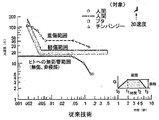
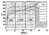
図9において、損傷レベルを加速度(y軸(G))と期間(x軸(秒))との関数として表している。同図より、負傷がある期間に受ける、ある最小加速度の結果であることが分かる。加速度が充分に小さく及び/又は期間が充分に短く、図9における「負傷域」のない状態では、負傷を回避することができる。これは代表的なグラフであり他の研究によれば種々の領域においても明らかとなるであろうことが、この技術分野に精通している者にとっては、理解できるであろう。表1(AIS、1990年)に示すように、負傷の程度を定量的に評価するために、「簡易負傷指数(AIS)」が作成されている。 In FIG. 9, the damage level is expressed as a function of acceleration (y-axis (G)) and period (x-axis (second)). From this figure, it can be seen that this is the result of a certain minimum acceleration experienced during a period of injury. Injuries can be avoided in a state where the acceleration is sufficiently small and / or the period is sufficiently short and there is no “injury zone” in FIG. It will be appreciated by those skilled in the art that this is a representative graph and will become apparent in various areas according to other studies. As shown in Table 1 (AIS, 1990), a “Simple Injury Index (AIS)” has been created to quantitatively evaluate the degree of injury.

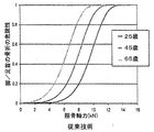
この指数の使用例として、NATO研究技術機関(RTO)のHFM−090タスクグループ25の最終報告書には、AIS指数2+(AIS指数2又はそれ以上)において危険度10%の負傷が装甲車(AV)の機雷爆発テストでの合否基準として許容されると決められてきたと記載されている。図11は、25歳、45歳及び65歳の対象者の足/足首負傷危険曲線を示している(ヨガナンダン・N 他、「人間の足/足首複合系の動的軸方向許容度」、文献番号962426、自動車技術協会、米国ペンシルベニア州ウォーレンデール、1996年)。図11の曲線によれば、25歳、45歳及び65歳の対象者の(上述のごとく規定した意味での)最大許容力は、それぞれ、危険度10%の足/足首骨折(AIS2+)を表す7.0、5.4及び3.8kNである。軍用車両内の大部分の人間(推定年齢20〜45歳)を保護するために、5.4kNの最終合否値(対象45歳)がTG−25によって選択されている。
As an example of the use of this index, the final report of the NATO Research and Technology Organization (RTO) HFM-090 Task Group 25 shows that an
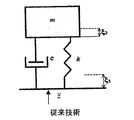
負傷軽減を研究するために有用な他の定量測定法として、動的応答指標(DRI)と呼ばれるものがある。この指標は図12に示した物理的システムに基づくものである。このシステムは、バネ定数kのバネと定数cの流体緩衝器とによって基体に接続された質量mを備えている。 Another quantitative measure useful for studying injury reduction is called Dynamic Response Index (DRI). This index is based on the physical system shown in FIG. The system comprises a mass m connected to the substrate by a spring with a spring constant k and a fluid buffer with a constant c.
DRIは、さらに、負傷の許容レベルを定量化するために用いられる。例えば、上述したNATOタスクグループは、17.7の最大DRI(AIS指数2又はそれ以上の10%の危険度に対応)について述べている。 DRI is further used to quantify the acceptable level of injury. For example, the NATO task group described above describes a maximum DRI of 17.7 (corresponding to a 10% risk with an AIS index of 2 or higher).
以下に説明する発明の1つの目的は、新規なエネルギ吸収シートに基づいた負傷軽減システム及び方法を提供することにある。 One object of the invention described below is to provide an injury reduction system and method based on a novel energy absorbing sheet.
本発明の好適な実施形態は、図1A〜図1Eに示すように、バネと同様の形状をしたコイル部材からなる。保持孔101は部材100を装着するために使用される。図1A及び図1Bの実施形態では、変化する断面103が採用されている。
As shown in FIGS. 1A to 1E, a preferred embodiment of the present invention includes a coil member having a shape similar to a spring. The holding
部材100は、引っ張り応力用に使用するために設計されており、充分に大きい力がかかると塑性変形するように構成されている。(ここでの「塑性」領域とは、物体が元の形態に通常は戻るバネのような「弾性」領域とは対照的に、その後の収縮を生じることなく変形を起こす応力の領域を称している。)この応力レベルが一致又は超過した場合は、図2(A)及び(B)に示すように、この部材に変形が起こる。この変形は、螺旋状切り込み105に沿った装置の「巻きほどき(unwinding)」でなされる。装置によってもたらされた捩れを解放すると共に螺旋状切り込みの端部における応力の集中を軽減するために、本実施形態では、歪緩和スロット102(図1A及び図1C)を用いている。応力の集中を軽減する構造については、この技術分野において自明の技術である。さらに、エネルギ吸収部材の回転を止めるか又は所定程度まで回転させて、装置の力−移動量曲線を制御できるようにすることも本発明の範囲である。エネルギ吸収素子に印加した力が所定の閾値より大きくなった場合のみ、塑性変形の領域に到達することに注意すべきである。印加した力がこの閾値を越えると、装置は、閾値力のみをシステムの他の保護する部分に伝達する。この閾値力は、装置の断面積を変化させるか、又は、壁の厚さが決まっている場合は螺旋状切り込み105のピッチを変化させることによって一定にすることができる。装置を大量生産した後であっても螺旋状切り込み105を設けることができるので、エネルギ吸収素子を大量生産した後に、必要に応じて変化するべき最終的な移動距離及び閾値反応力等の装置のパラメータを設定することができる。従来技術を越えた本発明の他の効果は、このシステムの残りの部分を再使用可能なことにある。エネルギ吸収装置だけが塑性変形を受ける部分であり、この装置は交換することができる。
The
図3を参照すれば、本発明のエネルギ吸収素子の力−移動量曲線の別の形態も理解できるはずである。弾性領域301において、装置は、印加される力と移動量とが線形特性を示すバネのような形態で機能し、印加される力が除去されると素子が元の形態に復帰する。(素子が少し移動した後に)急速に達する塑性領域302において、素子に印加可能な力は、概ね一定に維持され、エネルギ吸収部材の変形が継続すると僅かにのみ上昇する。最終領域303において、力は、継続する変位と共に益々急速に増大する。短い弾性領域及び許容移動量の最大長を持続させる塑性領域の特性はこのシステムにとって望ましい。これは、ほとんど移動量のないこの方法は、印加される力に対して反応することなく「浪費」されるためである。しかも、ほぼ全移動量が、図4(B)のグラフに示すように、設計理論上で計算される、ほぼ正確な要求される反応力を提供する。このグラフは、明らかに特定の実施形態に適応しており、他のグラフは異なる状況(壁や床等の異なる装着位置、異なる所望の加速度範囲、及びその他)に適応している。グラフの水平域領域には、理論的に可能なかぎり多くの衝撃エネルギを吸収しながら負傷を招くことなく衝撃力を伝達する望ましい効果があり、装置が移動量の終端に達すると、負傷をもたらす急激な加速度の可能性が低減する。衝撃エネルギが充分に吸収されなければ、この急激な加速度が生じ、それが原因で、最大許容加速度がこの量を超過することなく伝達される。当業者であれば明らかであるが、図3に示した関係は、単純な金属ロッド、バネ又はその他で得られる力−変位曲線から非自明でありかつ定量的に異なっている。また当然ながら、最大移動量を含む曲線の正確な形状と塑性領域における印加力の値との双方は、エネルギ吸収装置の長さ、螺旋状切り込みのピッチ、断面サイズ及び形状、材料、取り付け方法、並びにエネルギ吸収素子を設置する機械システムの設計を変えることで容易に調整できる。
With reference to FIG. 3, another form of the force-movement curve of the energy absorbing element of the present invention should be understood. In the
エネルギ吸収部品は、特定材料に限定するものではないが、低炭素鋼、ステンレス鋼、複合材料等々の塑性変形可能な材料より形成される。エネルギ吸収部品の好適な実施形態は、所望の衝撃負荷閾値に基づいて、所望の変形長さにわたって塑性変形できるように設計された螺旋バネ状の形態をとる。装置の動作特性(即ち、応力歪み曲線、従って、保護すべきシステムの変形長さ衝撃負荷閾値及び許容負荷範囲)は、下記のパラメータによって制御可能である。 The energy absorbing component is not limited to a specific material, but is formed from a plastically deformable material such as low carbon steel, stainless steel, or composite material. A preferred embodiment of the energy absorbing component takes the form of a helical spring designed to be plastically deformable over a desired deformation length based on a desired impact load threshold. The operating characteristics of the device (i.e. the stress strain curve and hence the deformation length impact load threshold and the allowable load range of the system to be protected) can be controlled by the following parameters:
1.素子の断面形状及び厚み
2.巻回ピッチ(長さ当りの巻回数)
3.長さ
4.材質
1. 1. Cross-sectional shape and thickness of element Winding pitch (number of windings per length)
3. Length 4. Material
本発明の1つ又はそれ以上のエネルギ吸収部品を備えた装置は、使用するエネルギ吸収部品の数と、1つ又はそれ以上のエネルギ吸収部品が組み込まれたシステムの機械設計とを変更することによって調整も可能である。 An apparatus with one or more energy absorbing components of the present invention is obtained by changing the number of energy absorbing components used and the mechanical design of a system incorporating one or more energy absorbing components. Adjustment is also possible.
本発明の効果は、既製の元の車両座席への追加部品として装着可能なことにある。また、いくつかの異なるタイプの座席及び車両に適応するよう製作でき、さらに、上述したように、異なる衝撃負荷作用を簡単に用意することができる。装置パラメータは、基台の構造及び重量、床からの有効空隙、並びに予想される最大の必要量サイズ等々を含むいくつかの因子の影響を受ける。図5A、図5B、図5C及び図6に示すような4バー機構に設けた際に、座席及び乗員に関して所望の力−変位曲線を生成するために必要なエネルギ吸収素子の力−変位曲線が、図4Aに示されている。図4Aに示した所望の反応曲線と実際の(測定した)反応曲線との比較が図4Bに示されている。実際の反応曲線は、理論的に望ましい曲線にかなり近いことが分かる。これは、シミュレーションによって究明できたように、装置の正しい動作を証明している。 An advantage of the present invention is that it can be mounted as an additional part on a ready-made original vehicle seat. It can also be made to accommodate several different types of seats and vehicles, and as described above, different impact loading effects can be easily prepared. Equipment parameters are affected by a number of factors, including base structure and weight, effective air gap from the floor, and maximum anticipated requirement size. When provided in a 4-bar mechanism as shown in FIGS. 5A, 5B, 5C and 6, the force-displacement curve of the energy absorbing element required to generate a desired force-displacement curve for the seat and the occupant is obtained. This is shown in FIG. 4A. A comparison between the desired response curve shown in FIG. 4A and the actual (measured) response curve is shown in FIG. 4B. It can be seen that the actual response curve is quite close to the theoretically desirable curve. This proves the correct operation of the device, as can be determined by simulation.
正しい動作の「本物の」証明を得るために、装置を実際の衝撃に晒してテストする必要がある。対象となる装置を試験システムに設置し、所定の負荷で装置に衝撃を与える。試験システムは、入出力加速度を測定し記録する。実際の衝撃下における装置の正しい動作が、図4Cに示す試験測定曲線に明確に現れている。ここで、測定された入力加速度401(例えば、車体が受ける加速度)と測定された出力加速度402(座席及び乗員が受ける加速度)とを時間当たりで示し、参考のために、時間当たりの設計出力加速度403も示している。y軸は加速度(G)であり、x軸は時間(秒)である。同図から分かるように、車両が受ける非常に大きい加速度(正弦波の半周期、0.005秒の期間で約205G)が一桁を超えて低減して4ミリ秒間に約22Gという負傷を受けないレベルの加速度となり、これに続いて0.03秒間に安定した17Gの加速度(同様に、加速度及び期間の組み合わせ条件も負傷を受けないレベル)まで降下した。また、このシステムは、商用利用されている有限要素法コードを用いた入念なシミュレーションによって確立されている設計値にかなり近い特性を発揮することが明らかになった。図示したシステムの特定の実施形態においては、乗員体重が116ポンド〜240ポンドの範囲まで有効であり、この体重範囲は全人口の90%を超えた(5パーセンタイルを超える女性から95パーセンタイル未満の男性)人口を含んでいる。 In order to obtain a “real” proof of correct operation, the device needs to be tested under real impact. The target device is installed in the test system, and the device is impacted with a predetermined load. The test system measures and records input / output acceleration. The correct operation of the device under actual impact is clearly shown in the test measurement curve shown in FIG. 4C. Here, measured input acceleration 401 (for example, acceleration received by the vehicle body) and measured output acceleration 402 (acceleration received by the seat and the occupant) are shown per time, and the design output acceleration per time for reference. 403 is also shown. The y-axis is acceleration (G), and the x-axis is time (seconds). As can be seen from the figure, the very high acceleration (sine wave half cycle, about 205G in a 0.005 second period) received by the vehicle is reduced by more than an order of magnitude, resulting in an injury of about 22G in 4 milliseconds. After that, the acceleration dropped to 17G acceleration (similarly, the combination condition of acceleration and period was not damaged) for 0.03 seconds. In addition, it has become clear that this system exhibits characteristics that are very close to the design values established by careful simulation using commercially available finite element method codes. In the particular embodiment of the system shown, the occupant weight is valid up to the range of 116 pounds to 240 pounds, and this weight range has exceeded 90% of the total population (greater than 5th percentile to less than 95th percentile male). ) Includes population.
図3、図4A、図4B及び図4Cの力-変位曲線に現れている繊細な効果について以下説明する。例えば図3の部分302のように、曲線の「水平」部分においては僅かな上昇が見られる。これは、以下の方法によって異なる体重の乗員に適応するために、このシステムの反応性を調整する効果を有している。体重の重い人と軽い人とが同じ減衰装置上に座ると、異なった作用が生じる。公称体重が105kg(23ポンド、乗員及び装置の合計)の対象用に設計したシステムの例について考察する。システムの減衰作用が、100mmの反応移動距離全体にわたって、105kgの乗員に17Gの加速度を与えたとする。前述の式1から算出できるように、同じ座席で最終重量(乗員及び装置)が128kgに達する体重の重い人は、例えば、移動距離121mmで14Gの加速度を受け、体重の軽い人は移動距離85mmで20Gの加速度を受けた。システムのこの性能を別の方法で説明すると、動的な力に応じて動的反応が変化し、実際には、体重の重い乗員及び軽い乗員の両方がこのシステムによって良好に保護される。一般に、このシステムを体重の重い乗員用に設計すると、軽い乗員はかなり大きく加速され、このシステムを体重の軽い乗員用に設計すると、重い乗員は充分に加速されず最終速度に達する前に移動量範囲を飛び出してしまい、結果として、移動量範囲の終端で急激な衝撃(衝突)を受けるため、この種のシステムの性能は決して明白なものものではないか、又は自然発生的なものではない。
The subtle effects appearing in the force-displacement curves of FIGS. 3, 4A, 4B, and 4C will be described below. There is a slight increase in the “horizontal” portion of the curve, eg,
このように、体重のより重い乗員だけが移動距離の終端に到達するので、移動距離が長いほどシステムは多少剛性を強くなっている。これら体重のより重い乗員は、その速度が最終速度に達するためには、運動量の大きな変化を受けねばならない。このため、移動距離の終端において体重のより重い乗客に大きい力を与えることは、重い乗客と軽い乗客との根本的な移動距離の差を少なくする効果をもたらし、本質的に、同一のシステムで重い乗客及び軽い乗客の両方により良好に適合する。負荷形態の変化は、実際、技術文献で公知であり、可変負荷エネルギ吸収装置(VLEA)と参照される。このようなシステムは、通常、特定の乗員の体重に合わせて事前に又は自動的に調整されるようになっており、本発明による装置に比べて著しく複雑な構成となる。一方、固定負荷エネルギ吸収装置(FLEA)は、このような制御を行わないため、上述したごとき問題が生じない。即ち、軽い乗員の体重範囲に適しており、その範囲外の体重の乗員には不適となる。実際に、本発明では、移動距離に応じて負荷が大きくなる図3のような負荷特性とすることにより、機械的な複雑さを最小限にした改良型エネルギ吸収装置(AEA)を提供している。 Thus, only the heavier occupant reaches the end of the travel distance, so the longer the travel distance, the more rigid the system. These heavier occupants must undergo significant changes in momentum in order for their speed to reach their final speed. For this reason, giving a heavy force to a heavier passenger at the end of the travel distance has the effect of reducing the fundamental difference in travel distance between heavy and light passengers, essentially in the same system. Better fit for both heavy and light passengers. The change in load form is actually known in the technical literature and is referred to as a variable load energy absorber (VLEA). Such a system is usually adapted in advance or automatically in accordance with the weight of a specific occupant and is of a considerably more complex configuration than the device according to the invention. On the other hand, since the fixed load energy absorbing device (FLEA) does not perform such control, the above-described problem does not occur. That is, it is suitable for the weight range of light occupants and unsuitable for occupants with weights outside that range. In fact, the present invention provides an improved energy absorbing device (AEA) that minimizes mechanical complexity by adopting the load characteristics shown in FIG. 3 in which the load increases with the moving distance. Yes.
このシステムの他の有用な態様においては、エネルギ吸収素子の塑性変形により反発を最小限にできる(例えば、バネを用いた場合のように収縮・伸張後には初期状態に戻るものとは異なる)。反発エネルギは、このエネルギ吸収素子の、通常はS字状であるさらなる歪曲により吸収される。あらゆる反発力による付加的な加速度が乗員の危険性を高めるため、これは極めて有用な特性である。因みに、本発明のエネルギ吸収装置は、装置が最大限に伸張した後でも、より少ない伸張位置に押し戻す作用に抵抗する傾向があるため、システムの余力によってあらゆる反発作用を吸収する性質を有している。実際には、S字状に屈曲することにより、圧縮作用に対してある程度抵抗すると共にシステムの反発力を吸収する。 In another useful aspect of this system, rebound can be minimized by plastic deformation of the energy absorbing element (e.g., different from returning to the initial state after contraction / extension as in the case of using a spring). The repelling energy is absorbed by the additional distortion of this energy absorbing element, which is usually S-shaped. This is a very useful property because the additional acceleration due to any repulsive force increases occupant risk. Incidentally, since the energy absorbing device of the present invention tends to resist the action of pushing back to a less extended position even after the device is fully extended, it has the property of absorbing any repulsive action by the remaining power of the system. Yes. In practice, bending in an S-shape will resist the compression action to some extent and absorb the repulsive force of the system.
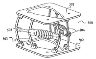
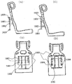
図5A、図5B及び図5Cを参照する。これらの図には、座席基部の構成要素としてエネルギ吸収素子の実施形態が示されている。図5Aは天板を外した平面図である。図5B及び図5Cはシステム全体の斜視図である。座席基部500は、座席板501上の座席(図示なし)を支持しており、床板502を用いて床に取り付けられる。装置の動きが縦方向の範囲を有することにより、乗員の受ける加速度を車両の受ける加速度より小さくすることができる。座席のこの縦方向の変位は、望ましくは4バー機構503を用いた本発明のエネルギ吸収素子504の線形運動に変換される。エネルギ吸収部品は、機構の先軸505に一体化されるか、又はシステムに負荷がかけられた際に互いに離間する機構の任意の2点間に並設される。上述したように、エネルギ吸収部品は、危険衝撃閾値に基づいて強制的に塑性軸変形させられる。
Please refer to FIG. 5A, FIG. 5B and FIG. 5C. In these figures, an embodiment of an energy absorbing element is shown as a component of the seat base. FIG. 5A is a plan view with the top plate removed. 5B and 5C are perspective views of the entire system. The
側方からの負荷に対処した好ましい実施形態においては、少なくとも2つの折畳み式機構に非平行に一体化されたエネルギ吸収部品が装着されている(図5A、図5B及び図5C)。他の実施形態においては、この技術分野で周知の多方向負荷に耐えるよう設計した機構構造と一体化されたただ1つのエネルギ吸収部品が適用される。 In a preferred embodiment that addresses side loads, energy absorbing components that are integrated non-parallel to at least two folding mechanisms are mounted (FIGS. 5A, 5B, and 5C). In other embodiments, a single energy absorbing component is applied that is integrated with a mechanical structure designed to withstand multi-directional loads well known in the art.
座席機構を車両の床に底板502若しくは補助金具(図示なし)を介して直接固定されるか、又は例えば側壁等の基台上の好ましい位置に接続される。この実施形態は、軍隊や航空機において受ける衝撃(航空機の着陸事故や機雷による縦方向の衝撃)では車両の床が最大の負荷を受けるので、軍隊及び航空機へ適用される衝突保護機構としては一般的なものである。車両の側面は、衝撃を弱め車両の残りの部分に伝わる勢いを低減するよう動作する車両の床のエネルギ吸収効果によって、より小さな負荷を受ける。従って、エネルギ伝搬の観点から見ると、座席を衝撃点から可能な限り離れた、車両の側壁又は天井に取り付けることが有利である。これに対して、実際の設置の観点から見ると、座席は車両の床に取り付けることが有利である。当業者にとって、本発明がこのような設置の選択肢を全て包含していることは自明である。特に、本発明による多大なエネルギ吸収効果によれば、許容できる程度の加速度を座席に着いている乗員に伝達しつつ、座席を床に設置することが可能である。床に設置可能な本発明の装置の利点は、人間工学基準に基づき通常の座席を床で使用するのと同じ容積の使用で良い点にある。
The seat mechanism is fixed directly to the vehicle floor via a
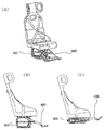
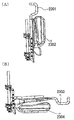
座席機構の一実施形態においては、足部保護装置600(図6(A)、(B)及び(C)参照)を備えている。この足部保護装置は足部を置くように構成されており、図6(C)に示すように座席保護装置601が付勢された場合(閾値以上の加速度を受けた場合)、足部を床から浮き上がらせる。好ましくは、乗員の身体に伝達される衝撃波を最小限にするために、足支持軸が座席機構の上部に連結される。従来技術(例えば、米国特許第6267440号明細書)に記載されているいくつかの例とは異なり、本発明の好適な実施形態における足部保護機構は、脛部を前方に伸張させるというより大腿骨盤の軸回りに足部を押し上げる自然運動をもたらす。最も一般的な車両では座席の前方の空間が制限されているので、これは望ましい構成である。足及び下肢の骨折/骨粉砕等の多くの地雷による損傷は、移動中(及び衝撃中)に、乗員の足が車両の床上に置かれていることが原因となるので、本発明のシステムは多くの重篤なこの種の損傷を劇的に減らす効果がある。
In one embodiment of the seat mechanism, a foot protection device 600 (see FIGS. 6A, 6B, and 6C) is provided. This foot protection device is configured to place the foot, and when the
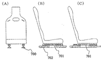
爆発は、ある範囲の振動及び衝撃波を座席及びエネルギ吸収機構にもたらす。高周波の振動や衝撃波を弱めるためには、必須ではないが、この技術分野では公知の吸収エラストマ(通常は機械エネルギを熱に変換する素子)を介して機械部分の結合部及び接続部を分離することが好ましい。本発明のエネルギ吸収部品は、また、水平衝撃(縦又は横方向の衝撃)を受けた際にこのエネルギ吸収部品を取り込みながら座席を水平方向に移動可能とする水平機構内に設置することによって、主に水平衝撃に対する保護に使用することができる。図7は、支持レール702を用いて水平運動を抑えるこの種の適用例を示している。エネルギ吸収部品701は2つの支持バー間に取り付けられ、各々は水平方向の運動のみを受け入れ、これに直交する方向の運動を抑える。長手方向の衝撃が一方の支持バーを付勢しエネルギ吸収部品を他方の支持バー方向に引っ張る。これは、本発明のエネルギ吸収部品を使用した実施形態例である。同様のエネルギ吸収部品を種々に改変実施できることは当業者にとって自明である。
The explosion brings a range of vibrations and shock waves to the seat and energy absorbing mechanism. It is not essential to weaken high-frequency vibrations and shock waves, but the coupling part and the connection part of the mechanical part are separated through an absorption elastomer (usually an element that converts mechanical energy into heat) known in this technical field. It is preferable. The energy absorbing component of the present invention can also be installed in a horizontal mechanism that allows the seat to move in the horizontal direction while taking in the energy absorbing component when subjected to a horizontal impact (longitudinal or lateral impact). Can be used mainly for protection against horizontal impact. FIG. 7 illustrates this type of application that uses support rails 702 to reduce horizontal motion. The
ここで説明した又は公知の補助機構を使用してこの種のエネルギ吸収部品を適切な方向に配設することによって、あらゆる方向の運動抑制効果を実現できる。適用負荷の安全な範囲を広げるために、弾性バンパー801を図8(A)及び(B)に示したように設置することができる。これらバンパーは、機構の動作に必須のものではない。これらバンパーは、移動範囲の終端のみで動作し、負荷−変位特性曲線の最終段階を修正し、移動量の関数として負荷をさらに増大させる。これは、さもなければ移動量の終端において受けとるものであり、例えば2つの金属部材が最終的に接触し、劇的に増大する負荷を伝達して実質的に加速度を著しく高める「発作的な動き(jerk)」を最小限にする傾向にある。
By arranging this type of energy absorbing component in an appropriate direction using the auxiliary mechanism described here or known, a movement suppressing effect in all directions can be realized. In order to widen the safe range of the applied load, the
図10(A)〜(D)は、車両の側壁に座席を取り付けた本発明の一実施形態を示している。装置は、ネジ、ボルト、クランプ、又は当業者に自明の他の方法を用いて、取り付け点1003に取り付けられている。図10(A)は衝撃を受ける前の装置を背面から見た図、図10(B)は衝撃を受ける前の装置を側面から見た図を示している。取り付け点1004は、本発明のエネルギ吸収素子1001を介して装置を座席に取り付けている。図10(C)の側面図と図10(D)の背面図に示したように、取り付け金具1002は、エネルギ吸収素子1001が伸張した時に座席が縦方向に摺動できるようにしている。
10 (A) to 10 (D) show an embodiment of the present invention in which a seat is attached to the side wall of a vehicle. The device is attached to
この壁取り付けの実施形態においては、取り付け金具1002によって保持されるロッドにある程度の「撓み」を持たせ、心立てするために、取り付け金具1002内に自動調心ベアリングを組み込むことが有効である。印加される力が完全な張力でない場合にも螺旋自体が伸張できるので、壁取り付けシステムの最適な実施形態はこの分野で公知のあらゆる種類の自動調心基部に組み込まれるべきである。この種の取り付け金具を用いる他の利点は、構造が簡単であり、精巧なベアリング又は基部構造が不要であり、しかも安価なことにある。この技術は、種々の方法で実施することができる。即ち、ゴム、シリコン、皿バネ及びその他を含むあらゆる種類の可撓性部品がこのような取り付け金具に適している。
In this wall-mounted embodiment, it is effective to incorporate a self-aligning bearing in the mounting
本発明による座席システムの設計上の利点として次の事項を挙げることができる、
・構造が簡単(内部構造又は可動部を有しない単一のエネルギ吸収素子を使用)、
・低価格、
・種々の座席及び車両への拡張機能、
・軽量、
・取り付け時間及び作業の最小化(他用途への転用可能)、
・双方向抑制効果(初期ピーク及び反発の両方)、
・集積化された足部保護機構、
・多方向保護機能(水平及び縦方向両方の衝撃抑制可能)。
The following can be mentioned as the design advantages of the seat system according to the present invention,
-Simple structure (uses a single energy absorbing element with no internal structure or moving parts),
·Low price,
・ Extended functions for various seats and vehicles,
·lightweight,
・ Minimization of installation time and work (can be diverted to other applications)
-Bidirectional suppression effect (both initial peak and rebound),
-Integrated foot protection mechanism,
・ Multi-directional protection function (impact suppression in both horizontal and vertical directions).
本発明のエネルギ吸収装置の簡易性を、例えば、衝撃吸収システムによく用いられるピストン及びシリンダシステムと比較する。ピストン及びシリンダは設計上最適な性能を得るために同軸に維持されなければならないが、爆発又はその他の強烈な加速度を受けるとピストン及びシリンダは同軸性を失い、減衰効果が低減するか又は全く喪失してしまう。これに対して、本発明のエネルギ吸収素子は「位置合わせ不良」にはなり得ない。本発明のエネルギ吸収素子は、その長手軸に非平行ないかなる応力(例えばせん断応力)も素子の変形によりほとんど吸収され、いかなる場合も、装置のエネルギ吸収能力及び加速度制限性能を損なうことはない。 The simplicity of the energy absorbing device of the present invention is compared with, for example, a piston and cylinder system often used in shock absorbing systems. Pistons and cylinders must be kept coaxial for optimum design performance, but when subjected to an explosion or other intense acceleration, the pistons and cylinders lose their coaxiality and the damping effect is reduced or lost at all Resulting in. On the other hand, the energy absorbing element of the present invention cannot be “misalignment”. In the energy absorbing element of the present invention, any stress (for example, shear stress) that is not parallel to the longitudinal axis is almost absorbed by the deformation of the element, and in any case, the energy absorbing ability and acceleration limiting performance of the device are not impaired.
さらに本発明によれば、車両の乗員が着座する座席は、車両の動き(悪路走行、タイヤのバランス不良等々の原因による)から生じる振動を低減するある程度の緩衝作用を有している。例えば、図6の要素601のような4バー機構は、弾性保持部材(絶縁ゴム等)の使用によるある程度の「撓み」を有している。僅かな加速度については無視し改善しない他の多くの大衝撃用システムの場合とは異なり、本発明におけるこの撓みは悪路走行によって生じるような小さい加速度を吸収する性能を有している。
Furthermore, according to the present invention, the seat on which the vehicle occupant is seated has a certain degree of buffering action to reduce vibrations caused by the movement of the vehicle (due to driving on rough roads, poor tire balance, etc.). For example, a 4-bar mechanism such as the
図13は本発明の床取り付けタイプの実施形態を示している。図13の(A)は装置の正面図、(B)は側面図、(C)は等角図である。この座席は、小さい振幅の加速度及び振動をさらに吸収するある程度の緩衝作用を持つ発泡体1301を備えている。
FIG. 13 shows a floor-mounted type embodiment of the present invention. 13A is a front view of the apparatus, FIG. 13B is a side view, and FIG. 13C is an isometric view. This seat is provided with a
図14は床取り付け機構全体を示しており、床取り付け板1401、座席取り付け板1403、及びエネルギ吸収部材1402が示されている。ゴムストッパ1404は、装置が移動範囲の終端に達する場合に働くように設けられている。ゴムストッパ1404は、装置が移動するにつれて徐々に反発力を増大させ、装置が移動範囲の終端に極限速度で達するかそれを超える可能性(例えば、上板及び底板間の金属接触や反発力の突然の増大)を低減している。
FIG. 14 shows the entire floor mounting mechanism, in which a
図15は、壁取り付け機構をさらに詳細に示している。壁取り付け板1501及び1503は、装置を車両に壁面に取り付ける。座席取り付け板1505は座席を所定の位置に保持する。エネルギ吸収部材1502はこれら2つの取り付け点を連結している。壁取り付け板1501及び1503はエネルギ吸収部材1502が伸張する際にシリンダ1504上を摺動可能である。図15(C)に示すように、せん断ピン1506が負荷−移動特性に初期スパイクを供給するために利用できる。加速度に短いが高振幅のスパイクをもたらすことにより、他の方法では行えなかった、著しく大きな入力運動量を吸収することができ、しかも持続時間が充分に短かければ(例えば図9を参照して判断できる)、着座乗員に対する負傷リスクを容認できるほど小さくすることができる。
FIG. 15 shows the wall mounting mechanism in more detail.
図16のグラフは、「2回の衝撃」の想定例におけるシステムの反応を示している。最初のピーク1601は爆発による加速度であり、第2のピーク1602は強烈な叩きつけ(slam-down)(即ち、車両が地雷の爆風に煽られた後に地面に叩きつけられた状況)を示している。同図から分かるように、最初の最大加速度は、5.5ミリ秒の間に約400Gに達し、DRIレベル1603は17.7の許容限界をはるかに下回っている。
The graph of FIG. 16 shows the reaction of the system in the assumed example of “two impacts”. The
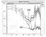
図17のグラフは「多回の衝撃」の想定例の場合である。このテストは自由落下タワーで実施された。最初のピークは210Gが5.5ミリ秒間であり、続くピーク1702は80〜100Gであった。これから分かるように、DRIレベル1701はかなり低い。
The graph of FIG. 17 is an example of an assumption example of “multiple impacts”. This test was conducted in a free fall tower. The first peak was 210G at 5.5 milliseconds and the
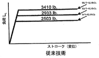
衝撃吸収システムを設計する主たる課題の1つは、種々の乗員体重への対応を可能にすることである。異なる体重の乗員には、システムから異なる反応が必要であることは当然である。体重の軽い乗員は小さいストロークで大きい加速度を受け、体重の重い乗員は長いストロークで小さい加速度を受けることも知られている。これについては、3つの互いに異なる体重の乗員について所望の負荷(y軸)に対する変位(x軸)を表す、図18Aの代表的な負荷−変位曲線に示されている。より重い乗員が衝撃減衰システムによってより軽い乗員より大きい力で駆動されることが望ましい。より重い乗員のより大きい質量によって大きい力が相殺され、重い乗員及び軽い乗員に対して同じ加速度をもたらすこととなる。このような結果を実現するために、弾性範囲に沿った変位と共に変化する、図18Bに示すような負荷−変位曲線が提供される。ここでは、負荷は、最初のピーク1801の後に最初の平坦値1802となる。ある量の変位の後、負荷は、第2の高い値1803に増加する。高振幅の短い加速度が存続し(図9参照)、衝撃エネルギをある程度吸収するため、最初のピークが有効である。
One of the main challenges in designing an impact absorbing system is to allow for different occupant weights. Of course, passengers of different weights need different responses from the system. It is also known that a light occupant receives a large acceleration with a small stroke, and a heavy occupant receives a small acceleration with a long stroke. This is shown in the representative load-displacement curve of FIG. 18A, which represents the displacement (x axis) relative to the desired load (y axis) for three different weight occupants. It is desirable for heavier occupants to be driven with greater force than lighter occupants by an impact damping system. The greater mass of the heavier occupant cancels out the greater force, resulting in the same acceleration for heavy and light occupants. To achieve such a result, a load-displacement curve as shown in FIG. 18B is provided that varies with displacement along the elastic range. Here, the load becomes the first
最近の改良システムでは、図18Bのような可変負荷−ストローク特性をシステムが備えるように設計することでこの要求に対応するようにしている。このようなシステムは、ストローク開始時においては小さい力、終端においては大きい力であることが特徴である。一般に「改良型EA」と称されるこのようなシステムは、構造がかなり複雑であり、製造コストが高い。このような可変力曲線を得るために、システムは、通常、異なるストローク/力特性を各々が有するいくつかのサブシステムからなる複雑な機構を備えている。このようなシステムの複雑さは明らかに大きな欠点である。 In recent improved systems, this requirement is met by designing the system to have variable load-stroke characteristics as shown in FIG. 18B. Such a system is characterized by a small force at the beginning of the stroke and a large force at the end. Such a system, commonly referred to as “modified EA”, is quite complex in structure and expensive to manufacture. In order to obtain such a variable force curve, the system usually comprises a complex mechanism consisting of several subsystems each having different stroke / force characteristics. The complexity of such a system is clearly a major drawback.
本発明の改良型システムは、既述した単体のエネルギ吸収素子に基づいている。この装置のコイル状又はバネ状の構造と用いる材料の変形特性との必然的効果として、ストロークに応じて負荷が増大する。従って、このシステムは、体重に関係なく広い範囲の乗員に許容可能な加速度を供給する。 The improved system of the present invention is based on the single energy absorbing element described above. As a necessary effect of the coil-like or spring-like structure of this device and the deformation characteristics of the material used, the load increases with the stroke. Thus, this system provides acceptable acceleration for a wide range of passengers regardless of weight.
このシステムは単一の構成要素に基づくため、高い信頼性と反復可能性を享受できる。環境条件もこのシステムの性能に影響を及ぼすことはなく、埃、泥、油等々にも左右されない。このシステムは常に設計通りに、かつ製造時の性能で稼働する。
2つ又はそれ以上の部品の相互作用を利用した他のシステムは、通常、摩擦力若しくは粘性力に影響され、さらには、環境温度、泥、砂若しくは油等の侵入、高温ガス等のように、システムに障害、熱損又は爆発若しくは他の原因による衝撃を受ける前若しくは受けている際に異変をもたらすような環境条件に必然的に影響される。
Since this system is based on a single component, it can enjoy high reliability and repeatability. Environmental conditions do not affect the performance of the system and are not affected by dust, mud, oil, etc. The system always operates as designed and with production performance.
Other systems that make use of the interaction of two or more parts are usually affected by frictional or viscous forces, as well as environmental temperature, intrusion of mud, sand or oil, hot gases, etc. Inevitably affected by environmental conditions that cause anomalies before or during the impact of a system failure, heat loss or explosion or other causes.
本発明の負荷−変位曲線は上述した動作性能のタイプを示している。図19は本発明のエネルギ吸収素子の負荷−変位曲線(別名、力-移動量曲線)を示している。本発明のシステムが提案する反発力1901は、移動範囲の最初で約4500N(初期弾性変形)であり、約175mm移動した後に約6500Nに徐々に増大する。この変化は、突然ではなく、「発作的な動き(jerk)」(d3z/dt3)のない徐々の変化である。システムのパラメータ(断面積、長さ、ピッチ、材料)を変化させることにより、広範囲な負荷−変位曲線を実現できることに注目すべきである。
The load-displacement curve of the present invention indicates the type of operational performance described above. FIG. 19 shows a load-displacement curve (also called force-movement amount curve) of the energy absorbing element of the present invention. The
図20は振動分析結果を示している。同図において、x軸は振動周波数(Hz又は1/秒)、y軸は振動振幅(G(対数))である。入力加速度2002については、大部分の周波数範囲において伝搬加速度2001の場合よりかなり大きく、約100Hz〜約500Hzの周波数範囲から、伝搬加速度については10〜100倍ほど減衰している。この振動の減衰は、システムが備えられている「撓み」の度合に基づくものであり、他の衝撃保護システムでは特別に設定しない限りは通常は得られないものである。このような振動の減衰は、乗員が連続的な振動で疲労し神経を擦り減らす、陸上車又は戦闘用ヘリコプタ等の他の乗り物による悪路(イラクの田園地帯等)の長時間移動に有用である。このような解析を振動の種々の軸について実施し、同様な結果が全ての方向について得られた。
FIG. 20 shows the vibration analysis result. In the figure, the x-axis is the vibration frequency (Hz or 1 / second), and the y-axis is the vibration amplitude (G (logarithm)). The
装置を座席支持機構に上述したように取り付けることで、本発明による渦巻状又は螺旋状の部材が伸張後に張力だけでなく圧縮力にも抗するため、この装置は他のシステムで自然に見られるような反発作用を防止し、これによって、機構が跳ね返るのを防いでいる。実際の装置の一例を図21(A)〜(D)に示している。衝撃時の変形を見やすくするために白いライン2101を本発明の螺旋部材の上に重ねて表している。同図(A)は衝撃前のシステムを示している。同図(B)は初期衝撃を受け、エネルギ吸収素子が最大伸張状態になっているシステムを示している。同図(C)はエネルギ吸収素子が反発により直線状態から若干S字状に湾曲した形状に変形した反発後のシステムを示している。同図(D)はエネルギ吸収素子のその後の形状を示している。初期伸張状態から完全に伸張した状態に((A)から(B)に)素子が変形した際に、エネルギを吸収し伝搬加速度を抑え、さらに、エネルギ吸収素子が反発して((B)から(C)〜(D)に)変形し、同様にエネルギを吸収して伝搬する反発加速度を抑える。本発明の螺旋部材は何度もこの作用を繰り返すことができる。
By attaching the device to the seat support mechanism as described above, the device is naturally found in other systems because the spiral or spiral member according to the present invention resists not only tension but also compressive force after stretching. Such repulsive action is prevented, thereby preventing the mechanism from bouncing back. An example of an actual apparatus is shown in FIGS. In order to make the deformation at the time of impact easy to see, a
さらに本発明によれば、乗員が足を床から持ち上げる足載せ台が提供される。縦方向の爆発によって床が足部を突き上げることにより足及び下肢を骨折又は粉砕する非致死性の様々な負傷が起きることが知られている。単純に足先を床から離すことで、このような負傷をかなり回避することができる。本発明のシステムは、図22に示すような収縮機構2201によってさらなる保護を行うことができる。同図(A)に示すように、この収縮機構2201は常時は伸張している。衝撃時、収縮機構2201は、同図(B)に示すように引っ込み、起こりうる床の変形又は破裂から足を持ち上げて離間させる。このような姿勢は、足及び足部に与える縦方向衝撃への最適な対処についてのNATOの研究(NATO研究技術機関(RTO)のHFM−90タスクグループ25の最終報告)により明らかにされている。
Furthermore, according to this invention, the footrest from which a passenger | crew lifts a foot from a floor is provided. It is known that various non-lethal injuries that cause fractures or crushing of the legs and lower limbs due to the floor pushing up the foot by a longitudinal explosion. Such injuries can be substantially avoided by simply moving the toes off the floor. The system of the present invention can provide further protection by a
さらに、座席が折り畳み可能である構成も本発明の範囲に含まれる。図23(A)及び(B)はこのような折り畳み可能な構成を示している。ヘッドレストはその展開位置2301から折り畳み位置2303へと折り畳み可能であり、着座部はその直立位置2302から展開位置2304へと折り畳み可能である。
Further, a configuration in which the seat can be folded is also included in the scope of the present invention. FIGS. 23A and 23B show such a foldable configuration. The headrest can be folded from its deployed
本発明によれば、また、危険な縦衝撃エネルギ及び横衝撃エネルギを、所定の衝撃負荷閾値内で反応するように設計された、固体部品の塑性変形に変換することが提供される。 The present invention also provides for the conversion of dangerous longitudinal impact energy and lateral impact energy into plastic deformation of a solid part designed to react within a predetermined impact load threshold.
本発明によれば、さらに、乗員が車両とは別個に加速度を受けることを可能とするために、動きの最小安全範囲が提供される。 The present invention further provides a minimum safe range of motion to allow an occupant to receive acceleration separately from the vehicle.
本発明によれば、またさらに、乗員に伝わる加速度を安全限界内に制限するように垂直加速度及び水平加速度の両方を減衰させる実施形態が提供される。 In accordance with the present invention, there is further provided an embodiment in which both vertical and horizontal acceleration are attenuated so as to limit the acceleration transmitted to the occupant within safety limits.
本発明によれば、さらに、システムが衝撃に反応した際に乗員の足を床から浮かせ、大腿骨盤軸回りに足部を持ち上げる足部保護機構の他の実施形態が提供される。 The present invention further provides another embodiment of a foot protection mechanism that floats the occupant's foot off the floor and lifts the foot about the femoral pelvic axis when the system responds to an impact.
本発明によれば、またさらに、正面衝突のような主に水平衝撃に対処できる吸収部品を設けた他の実施形態が提供される。 According to the present invention, still another embodiment is provided in which an absorbing component capable of coping with mainly horizontal impact such as a frontal collision is provided.
このシステムのテスト(米国陸軍研究所(ミシガン州連邦研究所)、イスラエル・ミリタリー・インダストリーズ等で実施)により、本発明のシステムの実施形態は、NATO研究技術機関(RTO)のHFM−090タスクグループ25の性能基準、即ち、最大DRI17.7に適合した。 Through testing of this system (performed by the US Army Research Laboratory (Michigan Federal Institute), Israel Military Industries, etc.), the embodiment of the system of the present invention is the NATO Research and Technology Organization (RTO) HFM-090 Task Group. 25 performance criteria were met, ie maximum DRI 17.7.
本発明の実施形態のほとんどにおいて、実際の性能は、下表に示すように、厳密に必要とされる性能より良好であった。 In most of the embodiments of the present invention, the actual performance was better than the strictly required performance, as shown in the table below.
Claims (23)
(b)前記螺旋状リボンの両端部に設けられた取り付け手段と、
を備えており、
前記螺旋状リボンの力−変位曲線が、エネルギ吸収機構の長さ、径、厚さ、切り込みサイズ、切り込み螺旋度、及び材料によって決まる所定の形態で特徴付けられているエネルギ吸収機構。 (A) forming a spiral ribbon that undergoes plastic deformation in response to a stress greater than a predetermined threshold stress along its axis, and a cylinder having a spiral cut along said axis;
(B) attachment means provided at both ends of the spiral ribbon;
With
An energy absorbing mechanism in which a force-displacement curve of the spiral ribbon is characterized by a predetermined form determined by the length, diameter, thickness, cutting size, cutting spiral degree, and material of the energy absorbing mechanism.
(a)張力を受けた際に塑性変形するように構成された1つ又はそれ以上の螺旋状リボンと、
(b)前記縦方向の衝撃からの運動量を前記螺旋状リボンの張力に変換するように構成された機械リンク機構と、
(c)前記機械リンク機構の第1の領域を車両の座席に取り付ける取り付け手段と、
(d)前記機械リンク機構の第2の領域を車両の車体に取り付ける取り付け手段と、
を備えており、
前記衝撃からの運動量により、前記螺旋状リボンの長さ、ピッチ、断面、及び材料によって調整可能な応力レベルで、ある程度の塑性変形を起こさせる張力を、前記螺旋状リボンに発生させる装置。 A device for protecting a seated occupant from longitudinal impacts,
(A) one or more helical ribbons configured to plastically deform when subjected to tension;
(B) a mechanical linkage configured to convert momentum from the longitudinal impact into tension on the helical ribbon;
(C) attachment means for attaching the first region of the mechanical linkage to a vehicle seat;
(D) attachment means for attaching the second region of the mechanical link mechanism to the vehicle body;
With
A device for generating a tension in the spiral ribbon that causes a certain degree of plastic deformation at a stress level that can be adjusted by the length, pitch, cross section, and material of the spiral ribbon by the momentum from the impact.
(a)シリンダを供給するステップと、
(b)前記シリンダに螺旋通路に沿って切り込みを入れ、該シリンダを、螺旋状リボンの軸に沿った所定の閾値応力より大きい応力に反応して塑性変形を起こすと共に該螺旋状リボンの力−変位曲線が最終変位まで変位するために印加される力の平坦域に特徴付けられている当該螺旋状リボンに形成するステップと、
(c)前記螺旋状リボンの両端部に取り付け手段を設けるステップと、
(d)前記螺旋状リボンの長さ及び螺旋度を変化させることにより前記塑性変形の最終変位を制御するステップと、
(e)前記螺旋状リボンの断面及び材料を変化させることにより前記所定の閾値応力を制御するステップと、
(f)前記収容する身体と前記収容された本体との間に前記取り付け手段によって前記螺旋状リボンを介装することにより、前記収容された本体への衝撃により伝搬される応力を制限するステップと、
を備えている方法。 A method for minimizing the acceleration of a contained body due to an impact applied to the containing body,
(A) supplying a cylinder;
(B) making a cut in the cylinder along the spiral path, causing the cylinder to undergo plastic deformation in response to a stress greater than a predetermined threshold stress along the axis of the spiral ribbon and the force of the spiral ribbon— Forming a displacement curve on the helical ribbon characterized by a plateau of force applied to displace to final displacement;
(C) providing attachment means at both ends of the spiral ribbon;
(D) controlling the final displacement of the plastic deformation by changing the length and spirality of the helical ribbon;
(E) controlling the predetermined threshold stress by changing a cross-section and material of the spiral ribbon;
(F) limiting the stress propagated by impact on the accommodated body by interposing the helical ribbon by the attachment means between the accommodated body and the accommodated body; ,
A method comprising:
(a)複数の螺旋状リボンを供給するステップと、
(b)前記衝撃からの運動量を前記複数の螺旋状リボンの張力に変換するように構成した複数の機械リンク機構を供給するステップと、
(c)前記機械リンク機構を車両の座席に取り付ける第1の取り付け手段を供給するステップと、
(d)前記機械リンク機構を前記第1の取り付け手段を用いて前記車両の座席に取り付けるステップと、
(e)前記機械リンク機構を車両の車体に取り付ける第2の取り付け手段を供給するステップと、
(f)前記機械リンク機構を前記第2の取り付け手段を用いて前記車両の車体に取り付けるステップと、
(g)前記複数の螺旋状リボンの張力による該複数の螺旋状リボンの機械的変形により衝撃運動量を吸収するステップと、
を備えており、
前記複数の螺旋状リボンの長さ、ピッチ、断面、及び材料によって調整可能な応力レベルで、ある程度の前記機械的変形を前記複数の螺旋状リボンが受け、前記着座乗員に伝搬される衝撃力が前記複数の螺旋状リボンの力−変位曲線によって決定される方法。 A method for protecting a seated occupant from impact,
(A) supplying a plurality of spiral ribbons;
(B) supplying a plurality of mechanical linkages configured to convert momentum from the impact into tensions of the plurality of helical ribbons;
(C) supplying first attachment means for attaching the mechanical linkage to a vehicle seat;
(D) attaching the mechanical link mechanism to a seat of the vehicle using the first attachment means;
(E) supplying second attachment means for attaching the mechanical link mechanism to a vehicle body;
(F) attaching the mechanical link mechanism to the vehicle body of the vehicle using the second attachment means;
(G) absorbing impact momentum by mechanical deformation of the plurality of spiral ribbons due to tension of the plurality of spiral ribbons;
With
The plurality of spiral ribbons are subjected to a certain degree of mechanical deformation at a stress level that can be adjusted by the length, pitch, cross section, and material of the plurality of spiral ribbons, and an impact force transmitted to the seated occupant is generated. A method determined by a force-displacement curve of the plurality of spiral ribbons.
(a)1つ又はそれ以上の螺旋状リボンを供給するステップと、
(b)前記衝撃を前記1つ又はそれ以上の螺旋状リボンの伸張に変換するように構成した機構を供給するステップと、
(c)前記1つ又はそれ以上の螺旋状リボンを車両の座席に取り付ける前部取り付け手段を供給するステップと、
(d)前記1つ又はそれ以上の螺旋状リボンを前記前部取り付け手段を用いて前記車両の座席に取り付けるステップと、
(e)前記1つ又はそれ以上の螺旋状リボンの後部を車両の車体に取り付ける後部取り付け手段を供給するステップと、
(f)前記1つ又はそれ以上の螺旋状リボンを前記後部取り付け手段を用いて前記車両の車体に取り付けるステップと、
(g)前記1つ又はそれ以上の螺旋状リボンの伸張により衝撃を吸収するステップと、
を備えており、
前記車両の座席に伝搬される前記衝撃の力が前記1つ又はそれ以上の螺旋状リボンの力−変位曲線によって決定され、前記1つ又はそれ以上の螺旋状リボンは、該1つ又はそれ以上の螺旋状リボンの長さ、ピッチ、断面、及び材料によって調整可能な応力レベルで、ある程度の塑性変形を受ける方法。 A method for protecting a seated occupant from impact,
(A) supplying one or more helical ribbons;
(B) providing a mechanism configured to convert the impact into stretching of the one or more helical ribbons;
(C) providing front attachment means for attaching the one or more helical ribbons to a vehicle seat;
(D) attaching the one or more helical ribbons to a seat of the vehicle using the front attachment means;
(E) supplying rear attachment means for attaching a rear portion of the one or more helical ribbons to a vehicle body;
(F) attaching the one or more helical ribbons to a vehicle body of the vehicle using the rear attachment means;
(G) absorbing impact by stretching the one or more helical ribbons;
With
The impact force transmitted to the vehicle seat is determined by a force-displacement curve of the one or more spiral ribbons, the one or more spiral ribbons being the one or more To undergo some degree of plastic deformation at a stress level adjustable by the length, pitch, cross section and material of the spiral ribbon.
Applications Claiming Priority (3)
| Application Number | Priority Date | Filing Date | Title |
|---|---|---|---|
| US10325108P | 2008-10-07 | 2008-10-07 | |
| US61/103,251 | 2008-10-07 | ||
| PCT/IL2009/000220 WO2010041235A1 (en) | 2008-10-07 | 2009-02-26 | Shock absorbing mechanism with feet protection for vehicle and aircraft seats |
Publications (1)
| Publication Number | Publication Date |
|---|---|
| JP2012505108A true JP2012505108A (en) | 2012-03-01 |
Family
ID=40810126
Family Applications (1)
| Application Number | Title | Priority Date | Filing Date |
|---|---|---|---|
| JP2011530628A Pending JP2012505108A (en) | 2008-10-07 | 2009-02-26 | Shock absorbing mechanism for vehicle and aircraft seats with foot protection function |
Country Status (7)
| Country | Link |
|---|---|
| US (1) | US9283874B2 (en) |
| EP (1) | EP2342475B1 (en) |
| JP (1) | JP2012505108A (en) |
| KR (1) | KR20110083653A (en) |
| CN (1) | CN102282385A (en) |
| TR (1) | TR201909172T4 (en) |
| WO (1) | WO2010041235A1 (en) |
Cited By (1)
| Publication number | Priority date | Publication date | Assignee | Title |
|---|---|---|---|---|
| JP2017219065A (en) * | 2016-06-03 | 2017-12-14 | 新日鐵住金株式会社 | Energy absorption device, earthquake proof wall and aseismic base isolation structure |
Families Citing this family (37)
| Publication number | Priority date | Publication date | Assignee | Title |
|---|---|---|---|---|
| EP2144784A2 (en) * | 2007-05-07 | 2010-01-20 | Arjuna Indraeswaran Rajasingham | Occupant support system |
| WO2011039754A1 (en) * | 2009-10-02 | 2011-04-07 | Mobius Protection Systems Ltd. | Shock absorbing device |
| WO2011077436A1 (en) | 2009-12-24 | 2011-06-30 | Mobius Protection Systems Ltd. | Energy absorbing elements |
| US8714642B2 (en) | 2010-03-31 | 2014-05-06 | Survivability Solutions Llc | Blast attenuation seat |
| CA2795824A1 (en) | 2010-05-03 | 2011-11-10 | Weber Aircraft Llc | Seat support assembly |
| DE102010033419A1 (en) | 2010-08-04 | 2012-02-09 | Grammer Aktiengesellschaft | Horizon spring device for vehicle seats with elastomer spring element with progressive spring characteristic |
| DE102010051326A1 (en) * | 2010-08-31 | 2012-03-01 | Grammer Aktiengesellschaft | Vehicle seat for vehicles |
| DE102010052619A1 (en) | 2010-11-29 | 2012-05-31 | Grammer Aktiengesellschaft | Vehicle seat with guided scissor arms |
| DE102010053752A1 (en) | 2010-12-08 | 2012-06-14 | Grammer Aktiengesellschaft | Vehicle vibration device for vehicle seats or vehicle cabins |
| DE102011053647B4 (en) | 2011-09-15 | 2022-02-03 | Grammer Aktiengesellschaft | Vehicle seat with a suspension device and motor vehicle |
| US9132754B2 (en) | 2011-09-27 | 2015-09-15 | Mobius Protection Systems Ltd. | Safety seat |
| US9327623B2 (en) * | 2011-12-16 | 2016-05-03 | Wichita State University | Energy absorbing seat mechanism |
| DE102012208721A1 (en) | 2012-05-24 | 2013-11-28 | Lufthansa Technik Ag | Airplane seat with a seat assembly |
| US9051053B2 (en) * | 2013-01-10 | 2015-06-09 | Textron Innovations, Inc. | Seat base for aircraft |
| US10220734B2 (en) | 2013-03-05 | 2019-03-05 | Pidyon Controls Inc. | Car seat |
| US20150192183A1 (en) * | 2014-01-08 | 2015-07-09 | Sabic Innovative Plastics Ip B.V. | Energy management systems and methods for making and using the same |
| WO2016015877A1 (en) | 2014-07-29 | 2016-02-04 | Santa Bárbara Sistemas, S.A. | Armored land vehicle |
| US10272863B1 (en) * | 2014-10-31 | 2019-04-30 | Safe, Inc. | Structure and method for protecting a passenger during a crash |
| EP3018056B1 (en) * | 2014-11-04 | 2017-05-31 | Fusioncopter Sp. z o.o | Aircraft seat |
| US10480908B2 (en) | 2015-02-04 | 2019-11-19 | St Engineering Land Systems Ltd | Energy absorption system and device |
| MX2017013976A (en) | 2015-05-12 | 2018-03-14 | Pidyon Controls Inc | Car seat and connection system. |
| DE102015113176B4 (en) | 2015-08-10 | 2021-12-30 | Grammer Aktiengesellschaft | Horizontal vibration device for a vehicle seat |
| US10093203B1 (en) * | 2015-09-17 | 2018-10-09 | Armorworks Holdings, Inc. | Seating system with automatic weight compensating energy attenuation |
| DE102015118442B4 (en) * | 2015-10-28 | 2020-06-04 | Grammer Aktiengesellschaft | Vehicle seat with a device for seat stabilization |
| US10150392B2 (en) * | 2016-02-24 | 2018-12-11 | Ayyakannu Mani | Combat vehicle seat installation for protection of occupants from the effects of ground explosions |
| US10470576B2 (en) * | 2016-05-04 | 2019-11-12 | Aaron DeJule | Movable human support structure |
| DE102016213085A1 (en) * | 2016-07-18 | 2018-01-18 | Lufthansa Technik Ag | Airplane seat with a seat assembly |
| DE102017124349A1 (en) * | 2017-10-18 | 2019-04-18 | Recaro Aircraft Seating Gmbh & Co. Kg | Aircraft seat device with multipoint retention unit |
| CZ2017792A3 (en) * | 2017-12-11 | 2019-02-06 | BOGGES spol. s r.o. | Damping member, damping assembly and vehicle seat |
| FR3075908B1 (en) * | 2017-12-27 | 2020-09-25 | Airbus Operations Sas | DAMPING SYSTEM INCLUDING A PRIMARY DAMPER AND A SECONDARY DAMPER DEVICE FOR DIFFERENT STIFFNESS, ASSOCIATED STRUCTURE AND AIRCRAFT |
| US20190195310A1 (en) * | 2017-12-27 | 2019-06-27 | On Top Safety, Inc. | Force damper |
| IT201800009419A1 (en) * | 2018-10-12 | 2020-04-12 | Prinoth Spa | TRACKED VEHICLE FOR THE PREPARATION OF SKI SLOPES |
| US11007912B2 (en) | 2019-01-18 | 2021-05-18 | Pratt & Miller Engineering and Fabrication, Inc. | Energy attenuating vehicle seat assembly |
| DE102019105906B4 (en) * | 2019-03-08 | 2023-08-24 | Dr. Ing. H.C. F. Porsche Aktiengesellschaft | aircraft |
| EP3835204B1 (en) * | 2019-12-13 | 2024-02-28 | Adient Aerospace LLC | Carrier device, seating area divider and vehicle cabin |
| CN111572781B (en) * | 2020-04-27 | 2021-06-22 | 北京安达维尔航空设备有限公司 | Plate-type energy-absorbing crash-resistant seat |
| EP4316904A1 (en) * | 2022-08-04 | 2024-02-07 | B/E Aerospace, Inc. | Helical connecting link and method for energy absorption using the same |
Citations (7)
| Publication number | Priority date | Publication date | Assignee | Title |
|---|---|---|---|---|
| JPS4715766Y1 (en) * | 1971-07-08 | 1972-06-03 | ||
| JPH03128530U (en) * | 1990-04-09 | 1991-12-25 | ||
| JPH10122285A (en) * | 1996-10-22 | 1998-05-12 | Makino Milling Mach Co Ltd | Manufacture of cylindrical spring and cylindrical spring produced thereby |
| JPH10323258A (en) * | 1997-05-27 | 1998-12-08 | Honda Motor Co Ltd | Vehicle seat |
| JP2001289274A (en) * | 2000-04-06 | 2001-10-19 | Techno Quartz Kk | Spring made of brittle material and its manufacturing method |
| JP2002227898A (en) * | 2001-02-06 | 2002-08-14 | Tomoe Corp | Base isolating damper |
| JP2004291940A (en) * | 2003-03-28 | 2004-10-21 | T S Tec Kk | Vehicular seat |
Family Cites Families (24)
| Publication number | Priority date | Publication date | Assignee | Title |
|---|---|---|---|---|
| US1429580A (en) * | 1918-10-25 | 1922-09-19 | Geiger Paul Neal | Shaft coupling |
| US2131739A (en) * | 1936-12-30 | 1938-10-04 | Gulf Research Development Co | Helical ribbon spring measuring apparatus |
| US2777531A (en) * | 1954-10-22 | 1957-01-15 | Norman R Erickson | Emergency crash seat |
| US3068666A (en) * | 1959-12-16 | 1962-12-18 | Sabadash George | Torque transmitting device |
| FR1523248A (en) * | 1967-03-07 | 1968-05-03 | Thomson Houston Comp Francaise | Improvements in methods of manufacturing electrodes in the form of grids for electron tubes, electrodes manufactured using these improved methods and electron tubes containing such electrodes |
| FR1543275A (en) * | 1967-07-31 | 1968-10-25 | Peugeot | New, energy-absorbing arrangement of a seat on a vehicle |
| US3705740A (en) * | 1968-12-17 | 1972-12-12 | Toyota Motor Co Ltd | Collision force absorption device |
| US3802737A (en) * | 1972-07-07 | 1974-04-09 | Heizer K | Safety seat, particularly for automotive vehicles |
| US4260143A (en) * | 1979-01-15 | 1981-04-07 | Celanese Corporation | Carbon fiber reinforced composite coil spring |
| US4364603A (en) * | 1979-11-02 | 1982-12-21 | Pontiac Furniture, Inc. | Reclining chair |
| US4608739A (en) * | 1983-04-06 | 1986-09-02 | Big-Inch Marine Systems, Inc. | Connector of and sealing of tubular members |
| US4542708A (en) * | 1984-01-06 | 1985-09-24 | Raytheon Company | Composite cable fairing |
| US5167582A (en) * | 1986-07-31 | 1992-12-01 | Hunt Anthony O | Torque transmitting flexible coupling with helical spring element |
| US5749879A (en) * | 1989-08-16 | 1998-05-12 | Medtronic, Inc. | Device or apparatus for manipulating matter |
| US5690666A (en) * | 1992-11-18 | 1997-11-25 | Target Therapeutics, Inc. | Ultrasoft embolism coils and process for using them |
| US5290089A (en) * | 1992-12-28 | 1994-03-01 | General Motors Corporation | Seat bellows energy absorber |
| US5685603A (en) * | 1996-03-05 | 1997-11-11 | Trw Vehicle Safety Systems Inc. | Apparatus with a child seat and an energy absorption mechanism |
| WO1998045009A2 (en) * | 1997-04-04 | 1998-10-15 | Oiltools International B.V. | Filter for subterranean use |
| DE29718696U1 (en) * | 1997-10-21 | 1998-02-26 | Interco Ges Fuer Die Planung U | Movable seating arrangement |
| US6241691B1 (en) * | 1997-12-05 | 2001-06-05 | Micrus Corporation | Coated superelastic stent |
| US6145926A (en) * | 1998-11-17 | 2000-11-14 | Lin; Kuan Jen | Computer chair device |
| US6616232B2 (en) * | 2001-06-12 | 2003-09-09 | Hms Seating Inc. | Tiltable spring-biased chair |
| US20030075393A1 (en) * | 2001-10-24 | 2003-04-24 | Shields Roy E. | Positionable linear friction lock assembly |
| US7393214B2 (en) * | 2006-02-17 | 2008-07-01 | Centipede Systems, Inc. | High performance electrical connector |
-
2009
- 2009-02-26 JP JP2011530628A patent/JP2012505108A/en active Pending
- 2009-02-26 TR TR2019/09172T patent/TR201909172T4/en unknown
- 2009-02-26 WO PCT/IL2009/000220 patent/WO2010041235A1/en active Application Filing
- 2009-02-26 KR KR1020117010473A patent/KR20110083653A/en not_active Application Discontinuation
- 2009-02-26 EP EP09787431.7A patent/EP2342475B1/en active Active
- 2009-02-26 CN CN2009801489050A patent/CN102282385A/en active Pending
- 2009-02-26 US US13/123,195 patent/US9283874B2/en active Active
Patent Citations (7)
| Publication number | Priority date | Publication date | Assignee | Title |
|---|---|---|---|---|
| JPS4715766Y1 (en) * | 1971-07-08 | 1972-06-03 | ||
| JPH03128530U (en) * | 1990-04-09 | 1991-12-25 | ||
| JPH10122285A (en) * | 1996-10-22 | 1998-05-12 | Makino Milling Mach Co Ltd | Manufacture of cylindrical spring and cylindrical spring produced thereby |
| JPH10323258A (en) * | 1997-05-27 | 1998-12-08 | Honda Motor Co Ltd | Vehicle seat |
| JP2001289274A (en) * | 2000-04-06 | 2001-10-19 | Techno Quartz Kk | Spring made of brittle material and its manufacturing method |
| JP2002227898A (en) * | 2001-02-06 | 2002-08-14 | Tomoe Corp | Base isolating damper |
| JP2004291940A (en) * | 2003-03-28 | 2004-10-21 | T S Tec Kk | Vehicular seat |
Cited By (1)
| Publication number | Priority date | Publication date | Assignee | Title |
|---|---|---|---|---|
| JP2017219065A (en) * | 2016-06-03 | 2017-12-14 | 新日鐵住金株式会社 | Energy absorption device, earthquake proof wall and aseismic base isolation structure |
Also Published As
| Publication number | Publication date |
|---|---|
| US9283874B2 (en) | 2016-03-15 |
| CN102282385A (en) | 2011-12-14 |
| KR20110083653A (en) | 2011-07-20 |
| US20110233975A1 (en) | 2011-09-29 |
| EP2342475B1 (en) | 2019-04-03 |
| EP2342475A1 (en) | 2011-07-13 |
| TR201909172T4 (en) | 2019-07-22 |
| WO2010041235A1 (en) | 2010-04-15 |
Similar Documents
| Publication | Publication Date | Title |
|---|---|---|
| JP2012505108A (en) | Shock absorbing mechanism for vehicle and aircraft seats with foot protection function | |
| CA2801239C (en) | Blast attenuation seat | |
| US5813649A (en) | Energy-absorbing deformable bracket | |
| US6561580B1 (en) | Energy-absorbing aircraft seat | |
| EP0049043B1 (en) | Helicopter seat | |
| KR101653308B1 (en) | An anti-crash seat and an aircraft | |
| US8439420B2 (en) | Dual stage variable load energy absorber for vehicle seating | |
| JP2012532788A (en) | Energy absorber | |
| EP0828604A1 (en) | Energy absorbing structure | |
| US20080156602A1 (en) | Adaptive energy absorption system for a vehicle seat | |
| US20070034768A1 (en) | Shock-limiting interface, compact (SLIC) | |
| US10166889B1 (en) | Series mounted energy attenuator and spring damper | |
| US20140216242A1 (en) | Blast Attenuation Device For Absorbing Force Between An Occupant And A Vehicle | |
| CN107344515A (en) | Seat suspension installing mechanism and vehicle are fried in lightning protection | |
| US6964451B1 (en) | Shock absorbing apparatus | |
| CN212400993U (en) | Military vehicle seat buffering and isolating device | |
| EP2000352A1 (en) | Energy absorbing device for a vehicle seat | |
| EP3104113A1 (en) | Suspended perforated floor for armored vehicles | |
| RU2753774C1 (en) | Energy absorbing system and helicopter seat containing energy absorbing system | |
| Iluk | Selected aspects of the control of the human body motion in the vehicle subjected to the blast load | |
| US10578406B2 (en) | Suspended floor assembly | |
| KR100343363B1 (en) | An Impact Absorbing And Relaxative Device | |
| WO2011077436A1 (en) | Energy absorbing elements | |
| Jin et al. | Structures for Energy Dissipation in Safety Protection Systems | |
| IL175679A (en) | Energy absorbing device for vehicle seat |
Legal Events
| Date | Code | Title | Description |
|---|---|---|---|
| A621 | Written request for application examination |
Free format text: JAPANESE INTERMEDIATE CODE: A621 Effective date: 20120224 |
|
| A521 | Written amendment |
Free format text: JAPANESE INTERMEDIATE CODE: A523 Effective date: 20121120 |
|
| A977 | Report on retrieval |
Free format text: JAPANESE INTERMEDIATE CODE: A971007 Effective date: 20130619 |
|
| A131 | Notification of reasons for refusal |
Free format text: JAPANESE INTERMEDIATE CODE: A131 Effective date: 20130625 |
|
| A02 | Decision of refusal |
Free format text: JAPANESE INTERMEDIATE CODE: A02 Effective date: 20131119 |