JP2012505017A - Inhalation device and method of administering a medicament - Google Patents
Inhalation device and method of administering a medicament Download PDFInfo
- Publication number
- JP2012505017A JP2012505017A JP2011530993A JP2011530993A JP2012505017A JP 2012505017 A JP2012505017 A JP 2012505017A JP 2011530993 A JP2011530993 A JP 2011530993A JP 2011530993 A JP2011530993 A JP 2011530993A JP 2012505017 A JP2012505017 A JP 2012505017A
- Authority
- JP
- Japan
- Prior art keywords
- actuator
- cavity
- foil
- inhaler
- ethyl
- Prior art date
- Legal status (The legal status is an assumption and is not a legal conclusion. Google has not performed a legal analysis and makes no representation as to the accuracy of the status listed.)
- Granted
Links
Images


Classifications
-
- A—HUMAN NECESSITIES
- A61—MEDICAL OR VETERINARY SCIENCE; HYGIENE
- A61M—DEVICES FOR INTRODUCING MEDIA INTO, OR ONTO, THE BODY; DEVICES FOR TRANSDUCING BODY MEDIA OR FOR TAKING MEDIA FROM THE BODY; DEVICES FOR PRODUCING OR ENDING SLEEP OR STUPOR
- A61M15/00—Inhalators
- A61M15/0091—Inhalators mechanically breath-triggered
-
- A—HUMAN NECESSITIES
- A61—MEDICAL OR VETERINARY SCIENCE; HYGIENE
- A61M—DEVICES FOR INTRODUCING MEDIA INTO, OR ONTO, THE BODY; DEVICES FOR TRANSDUCING BODY MEDIA OR FOR TAKING MEDIA FROM THE BODY; DEVICES FOR PRODUCING OR ENDING SLEEP OR STUPOR
- A61M15/00—Inhalators
-
- A—HUMAN NECESSITIES
- A61—MEDICAL OR VETERINARY SCIENCE; HYGIENE
- A61M—DEVICES FOR INTRODUCING MEDIA INTO, OR ONTO, THE BODY; DEVICES FOR TRANSDUCING BODY MEDIA OR FOR TAKING MEDIA FROM THE BODY; DEVICES FOR PRODUCING OR ENDING SLEEP OR STUPOR
- A61M15/00—Inhalators
- A61M15/0001—Details of inhalators; Constructional features thereof
- A61M15/0003—Details of inhalators; Constructional features thereof with means for dispensing more than one drug
-
- A—HUMAN NECESSITIES
- A61—MEDICAL OR VETERINARY SCIENCE; HYGIENE
- A61M—DEVICES FOR INTRODUCING MEDIA INTO, OR ONTO, THE BODY; DEVICES FOR TRANSDUCING BODY MEDIA OR FOR TAKING MEDIA FROM THE BODY; DEVICES FOR PRODUCING OR ENDING SLEEP OR STUPOR
- A61M15/00—Inhalators
- A61M15/0001—Details of inhalators; Constructional features thereof
- A61M15/0021—Mouthpieces therefor
- A61M15/0025—Mouthpieces therefor with caps
- A61M15/0026—Hinged caps
-
- A—HUMAN NECESSITIES
- A61—MEDICAL OR VETERINARY SCIENCE; HYGIENE
- A61M—DEVICES FOR INTRODUCING MEDIA INTO, OR ONTO, THE BODY; DEVICES FOR TRANSDUCING BODY MEDIA OR FOR TAKING MEDIA FROM THE BODY; DEVICES FOR PRODUCING OR ENDING SLEEP OR STUPOR
- A61M15/00—Inhalators
- A61M15/0028—Inhalators using prepacked dosages, one for each application, e.g. capsules to be perforated or broken-up
- A61M15/003—Inhalators using prepacked dosages, one for each application, e.g. capsules to be perforated or broken-up using capsules, e.g. to be perforated or broken-up
- A61M15/0043—Non-destructive separation of the package, e.g. peeling
-
- A—HUMAN NECESSITIES
- A61—MEDICAL OR VETERINARY SCIENCE; HYGIENE
- A61M—DEVICES FOR INTRODUCING MEDIA INTO, OR ONTO, THE BODY; DEVICES FOR TRANSDUCING BODY MEDIA OR FOR TAKING MEDIA FROM THE BODY; DEVICES FOR PRODUCING OR ENDING SLEEP OR STUPOR
- A61M15/00—Inhalators
- A61M15/0028—Inhalators using prepacked dosages, one for each application, e.g. capsules to be perforated or broken-up
- A61M15/0045—Inhalators using prepacked dosages, one for each application, e.g. capsules to be perforated or broken-up using multiple prepacked dosages on a same carrier, e.g. blisters
- A61M15/0046—Inhalators using prepacked dosages, one for each application, e.g. capsules to be perforated or broken-up using multiple prepacked dosages on a same carrier, e.g. blisters characterized by the type of carrier
- A61M15/0048—Inhalators using prepacked dosages, one for each application, e.g. capsules to be perforated or broken-up using multiple prepacked dosages on a same carrier, e.g. blisters characterized by the type of carrier the dosages being arranged in a plane, e.g. on diskettes
-
- A—HUMAN NECESSITIES
- A61—MEDICAL OR VETERINARY SCIENCE; HYGIENE
- A61M—DEVICES FOR INTRODUCING MEDIA INTO, OR ONTO, THE BODY; DEVICES FOR TRANSDUCING BODY MEDIA OR FOR TAKING MEDIA FROM THE BODY; DEVICES FOR PRODUCING OR ENDING SLEEP OR STUPOR
- A61M15/00—Inhalators
- A61M15/0091—Inhalators mechanically breath-triggered
- A61M15/0093—Inhalators mechanically breath-triggered without arming or cocking, e.g. acting directly on the delivery valve
-
- A—HUMAN NECESSITIES
- A61—MEDICAL OR VETERINARY SCIENCE; HYGIENE
- A61M—DEVICES FOR INTRODUCING MEDIA INTO, OR ONTO, THE BODY; DEVICES FOR TRANSDUCING BODY MEDIA OR FOR TAKING MEDIA FROM THE BODY; DEVICES FOR PRODUCING OR ENDING SLEEP OR STUPOR
- A61M15/00—Inhalators
- A61M15/0091—Inhalators mechanically breath-triggered
- A61M15/0096—Hindering inhalation before activation of the dispenser
-
- A—HUMAN NECESSITIES
- A61—MEDICAL OR VETERINARY SCIENCE; HYGIENE
- A61P—SPECIFIC THERAPEUTIC ACTIVITY OF CHEMICAL COMPOUNDS OR MEDICINAL PREPARATIONS
- A61P43/00—Drugs for specific purposes, not provided for in groups A61P1/00-A61P41/00
-
- B—PERFORMING OPERATIONS; TRANSPORTING
- B65—CONVEYING; PACKING; STORING; HANDLING THIN OR FILAMENTARY MATERIAL
- B65D—CONTAINERS FOR STORAGE OR TRANSPORT OF ARTICLES OR MATERIALS, e.g. BAGS, BARRELS, BOTTLES, BOXES, CANS, CARTONS, CRATES, DRUMS, JARS, TANKS, HOPPERS, FORWARDING CONTAINERS; ACCESSORIES, CLOSURES, OR FITTINGS THEREFOR; PACKAGING ELEMENTS; PACKAGES
- B65D83/00—Containers or packages with special means for dispensing contents
- B65D83/04—Containers or packages with special means for dispensing contents for dispensing annular, disc-shaped, or spherical or like small articles, e.g. tablets or pills
-
- B—PERFORMING OPERATIONS; TRANSPORTING
- B65—CONVEYING; PACKING; STORING; HANDLING THIN OR FILAMENTARY MATERIAL
- B65D—CONTAINERS FOR STORAGE OR TRANSPORT OF ARTICLES OR MATERIALS, e.g. BAGS, BARRELS, BOTTLES, BOXES, CANS, CARTONS, CRATES, DRUMS, JARS, TANKS, HOPPERS, FORWARDING CONTAINERS; ACCESSORIES, CLOSURES, OR FITTINGS THEREFOR; PACKAGING ELEMENTS; PACKAGES
- B65D83/00—Containers or packages with special means for dispensing contents
- B65D83/06—Containers or packages with special means for dispensing contents for dispensing powdered or granular material
-
- A—HUMAN NECESSITIES
- A61—MEDICAL OR VETERINARY SCIENCE; HYGIENE
- A61M—DEVICES FOR INTRODUCING MEDIA INTO, OR ONTO, THE BODY; DEVICES FOR TRANSDUCING BODY MEDIA OR FOR TAKING MEDIA FROM THE BODY; DEVICES FOR PRODUCING OR ENDING SLEEP OR STUPOR
- A61M2202/00—Special media to be introduced, removed or treated
- A61M2202/06—Solids
- A61M2202/064—Powder
-
- A—HUMAN NECESSITIES
- A61—MEDICAL OR VETERINARY SCIENCE; HYGIENE
- A61M—DEVICES FOR INTRODUCING MEDIA INTO, OR ONTO, THE BODY; DEVICES FOR TRANSDUCING BODY MEDIA OR FOR TAKING MEDIA FROM THE BODY; DEVICES FOR PRODUCING OR ENDING SLEEP OR STUPOR
- A61M2205/00—General characteristics of the apparatus
- A61M2205/07—General characteristics of the apparatus having air pumping means
- A61M2205/071—General characteristics of the apparatus having air pumping means hand operated
- A61M2205/073—Syringe, piston type
Abstract
本発明は、医薬を含む少なくとも1つの気密ホイル密閉キャビティを有するベースを備えた吸入器に関する。アクチュエータが、ホイルに取り付けられた分離要素に係合し、このアクチュエータは、前記分離要素と前記取り付けられたホイルとが前記キャビティから分離されるようにこのアクチュエータが無負荷位置に向かって付勢される付勢位置を有する。ラッチが、アクチュエータを前記付勢位置にラッチする第1の位置を有し、このラッチは、流路を通る吸入気流がラッチを第1の位置から第2の位置に移動させるように少なくとも部分的に流路に配置されている。本発明はまた、吸入器内の密閉キャビティから医薬を投与する方法に関する。 The present invention relates to an inhaler with a base having at least one hermetic foil-sealed cavity containing a medicament. An actuator engages a separation element attached to the foil, which is biased toward an unloaded position so that the separation element and the attached foil are separated from the cavity. Has a biased position. A latch has a first position that latches the actuator in the biased position, and the latch is at least partially such that inhalation airflow through the flow path moves the latch from the first position to the second position. Arranged in the flow path. The invention also relates to a method for administering a medicament from a sealed cavity in an inhaler.
Description
本発明は、医薬を含む少なくとも1つの密閉キャビティを有するベースを備えた吸入器に関する。本発明はまた、吸入器内の密閉キャビティから医薬を投与する方法に関する。 The present invention relates to an inhaler with a base having at least one sealed cavity containing a medicament. The invention also relates to a method for administering a medicament from a sealed cavity in an inhaler.
様々な種類の吸入器が市販されている。加圧式定量噴霧吸入器(pMDI)は、一定量の物質を噴霧形態で放出する。粉末吸入器は、一般に、気流に引き込まれた1回分の粉末物質を放出する。粉末吸入器では、粉末を吸入器のバルクコンテナ内に含めることができ、このコンテナから、投薬のために所定用量の粉末が測定される。バルクコンテナの代わりとして、粉末吸入器は、単一区画または1つ以上の個別用量の粉末物質を含めるための複数の区画を備えることができる。このような区画は、ブリスタパックの密閉されたブリスタの形態、密閉ストリップに結合された、キャビティを含むストリップの形態、または他の適当な形態をとることができる。 Various types of inhalers are commercially available. A pressurized metered dose inhaler (pMDI) releases a certain amount of substance in a spray form. Powder inhalers typically release a dose of powdered material that is drawn into the air stream. In a powder inhaler, the powder can be contained in the bulk container of the inhaler, from which a predetermined dose of powder is measured for dosing. As an alternative to a bulk container, a powder inhaler can comprise a single compartment or multiple compartments for containing one or more individual doses of powdered material. Such a compartment may take the form of a sealed blister in a blister pack, a strip including a cavity coupled to a sealing strip, or other suitable form.
欧州特許第1220698号に、粉末形態の医薬用の吸入器が開示されている。医薬は、吸入器内の多数の密閉容器内に配置される。吸入器内の気流が一定の閾値に達すると、呼吸で作動する作動手段により、細長い中空本体が密閉容器に刺入して医薬に到達する。 EP 1220698 discloses a pharmaceutical inhaler in powder form. The medication is placed in a number of sealed containers in the inhaler. When the airflow in the inhaler reaches a certain threshold value, the elongated hollow body is inserted into the sealed container and reaches the medicine by the operating means activated by respiration.
米国特許第6,651,341号に、吸入器用の投与カセットに保持された1回分の医薬粉末を保護するホイルを開封するホイルカッター装置が開示されている。使用者が吸入器を介して吸入すると、予め定量された粉末用量に到達できるようにホイルカッターがホイルを開封する。 US Pat. No. 6,651,341 discloses a foil cutter device for opening a foil that protects a single dose of pharmaceutical powder held in a dosing cassette for an inhaler. When the user inhales through the inhaler, the foil cutter opens the foil so that a pre-quantified powder dose can be reached.
ホイルがカットまたは刺入される場合、ホイル材料の小片が分離されて使用者に吸引されるリスクがある。 When the foil is cut or stabbed, there is a risk that small pieces of foil material will be separated and sucked by the user.
国際出願第99/36116号に、一実施形態において、医薬キャビティを覆うホイルフラップを有する乾燥粉末吸入器が開示されている。ホイルフラップは、吸入気流によって持ち上げられ、これにより医薬が露出し、次いで気流と共に吸引されると記述されている。この実施形態は、同文献の図10に示されている。キャビティに対して接着もしくは溶接されるホイル、または気密シールもしくは水密シールを形成するホイルについては開示されていない。 International Application No. 99/36116 discloses, in one embodiment, a dry powder inhaler having a foil flap covering a pharmaceutical cavity. The foil flap is described as being lifted by the inhaled airflow, thereby exposing the medicament and then being aspirated with the airflow. This embodiment is shown in FIG. There is no disclosure of foil that is bonded or welded to the cavity or that forms an air or water tight seal.
本発明の目的は、キャビティシールを形成するホイル材料が使用者によって吸入されるリスクを低下させることにある。以下の説明で明らかになるこの目的および他の目的は、添付の特許請求の範囲で規定される吸入器および方法によって達成される。 The object of the present invention is to reduce the risk that the foil material forming the cavity seal is inhaled by the user. This and other objects, which will become apparent in the following description, are achieved by an inhaler and method as defined in the appended claims.
本発明は、医薬を含むキャビティの開口を覆うとともに、この開口にわたって密閉固定されたホイルの少なくとも一部を分離すること(カットまたは刺入するのとは対照的)によって、キャビティシールのホイル材料が医薬と共に吸入されるリスクを低減することができるという洞察に基づいている。ホイルの分離に関する潜在的な問題は、キャビティの内容物が動かされること、例えば、使用者が吸入する前に吸入器が反転されると弱いということである。この状況は、例えば、中空部材を用いてキャビティに刺入してから中空部材を介してキャビティの内容物を吸入する場合と比較することができ、この場合は、チューブおよびチューブの周りに残るホイルが、キャビティの内容物がキャビティから偶発的に出てしまうのを防止することができる。 The present invention covers the cavity opening containing the medicament and separates at least a portion of the foil hermetically secured across the opening (as opposed to cutting or piercing) so that the cavity seal foil material is It is based on the insight that the risk of being inhaled with medicines can be reduced. A potential problem with foil separation is that the contents of the cavity are moved, eg, weak if the inhaler is inverted before the user inhales. This situation can be compared, for example, to using a hollow member to penetrate the cavity and then inhaling the contents of the cavity through the hollow member, in which case the foil that remains around the tube and the tube However, it is possible to prevent the contents of the cavity from accidentally exiting the cavity.
この潜在的な問題は、息を吸い込むのと同時に蓋が持ち上げられる場合、吸入前に粉末がキャビティから出てしまう恐れがないため、呼吸による作動によって対処できる。実際、本明細書に開示される吸入器デザインは、反転した向きで試験され、キャビティの口が上を向いた通常の向きと実質的に同様に機能することが分かっている。 This potential problem can be addressed by breathing actuation because if the lid is lifted at the same time as inhaling, there is no risk of the powder exiting the cavity prior to inhalation. Indeed, the inhaler designs disclosed herein have been tested in an inverted orientation and have been found to function substantially the same as the normal orientation with the cavity mouth facing up.
本発明の第1の態様によって吸入器が提供される。この吸入器は、
医薬を含む少なくとも1つの密閉キャビティを有するベースと、
2つの面を有し、一方の面がベースに取り付けられ、前記キャビティを気密シールするホイル部と、
該ホイル部を前記キャビティから分離するために前記ホイル部の他方の面に取り付けられた分離要素と、
該分離要素に係合可能なアクチュエータを含む開放機構であって、このアクチュエータが、無負荷位置に向かって付勢される付勢位置を有し、該付勢位置から前記無負荷位置への移動の際に、アクチュエータが分離要素をキャビティから分離する、開放機構と、
アクチュエータを前記付勢位置にラッチする第1の位置とアクチュエータが前記無負荷位置になることを可能にする第2の位置とを有するラッチであって、流路を通る吸入流がラッチを第1の位置から第2の位置に移動させるように少なくとも部分的に前記流路に配置されている、ラッチと、を備える。
According to a first aspect of the invention, an inhaler is provided. This inhaler
A base having at least one sealed cavity containing a medicament;
A foil portion having two surfaces, one surface being attached to the base and hermetically sealing the cavity;
A separation element attached to the other side of the foil portion to separate the foil portion from the cavity;
An opening mechanism including an actuator engageable with the separation element, the actuator having a biasing position biased toward the no-load position, and moving from the biasing position to the no-load position An opening mechanism in which the actuator separates the separating element from the cavity;
A latch having a first position for latching an actuator in the biased position and a second position allowing the actuator to be in the unloaded position, wherein a suction flow through the flow path causes the latch to And a latch disposed at least partially in the flow path to move from the first position to the second position.
したがって、キャビティ内の医薬に到達するためにホイルに孔を開けるのではなく、ホイルを、例えば、ポキッと折るか、剥がすか、または持ち上げるなどして、キャビティから分離する。分離要素に取り付けられ、分離されたホイルは、流路画定要素としてさえも機能することができる。 Thus, rather than piercing the foil to reach the medication in the cavity, the foil is separated from the cavity, for example, by snapping, peeling or lifting. The foil attached to and separated from the separation element can function as even a flow path defining element.
本願では、「上側」、「下側」、「上」、「下」などの用語は、吸入器の要素間の内部の関係を記載するために説明目的で使用されることに留意されたい。したがって、本願では、吸入器が全体として使用者によってどのように保持または回転されるかにかかわらず、キャビティは、ホイル部の「下に」配置されていると見なされ、分離要素は、ホイル部の「上に」配置されていると見なされる。同様に、「水平」は、ホイル部の平面またはホイル部の平面に平行な任意の平面に位置する方向を意味し、「垂直」は、このような平面に直交する任意の方向を意味する。したがって、垂直線は、キャビティ、ホイル部、および分離要素と交差することができる。 It should be noted that in this application, terms such as “upper”, “lower”, “upper”, “lower” are used for illustrative purposes to describe internal relationships between elements of the inhaler. Thus, in this application, regardless of how the inhaler is held or rotated as a whole by the user, the cavity is considered to be located “below” the foil portion and the separating element is the foil portion. Is considered to be placed “on”. Similarly, “horizontal” means a direction located in the plane of the foil part or an arbitrary plane parallel to the plane of the foil part, and “vertical” means an arbitrary direction orthogonal to such a plane. Thus, the vertical line can intersect the cavity, the foil portion, and the separation element.
分離要素およびアクチュエータは、様々な方法でデザインすることができる。分離要素は、アクチュエータが係合して、下から押す力もしくは上から引っ張る力、または側方の引き上げもしくは持ち上げなどを行うことができる1つ以上のドッグ、突出部、凹部、フランジ、フック、チャンネルなどの構造的特徴を有することができる。アクチュエータは、径方向、回転方向または接線方向の動作など、分離要素に係合するための種々の動作を行うことができる。 The separation element and actuator can be designed in various ways. The separation element is one or more dogs, protrusions, recesses, flanges, hooks, channels that can be engaged by an actuator to push or pull from the top, or to lift or lift sideways. Structural features such as The actuator can perform various actions to engage the separation element, such as radial, rotational or tangential movement.
本発明の少なくとも1つの例示的な実施形態によると、アクチュエータは、分離要素に一時的に係合する係合部を有する旋回可能なレバーを備え、この係合部は、前記無負荷位置にあるときよりも前記付勢位置にあるときの方がキャビティに近接する。したがって、前記係合部は、初めにベースに向かって下げられ、次いで無負荷位置に向かって持ち上げられ、引き上げる力または持ち上げる力で分離要素に作用する。前記係合部は、例えば、分離要素の噛み合い突出部を把持する一対のジョーを有する。別の代替案として、前記係合部は、分離要素の噛み合いフォークグリップ内に挿入されるドッグを有してもよい。 According to at least one exemplary embodiment of the present invention, the actuator comprises a pivotable lever having an engagement portion that temporarily engages the separation element, the engagement portion being in the unloaded position. It is closer to the cavity when in the biased position than when. Accordingly, the engaging portion is first lowered toward the base and then lifted toward the unloaded position, and acts on the separating element with a lifting force or a lifting force. The engaging portion includes, for example, a pair of jaws that grip the meshing protrusion of the separation element. As another alternative, the engagement portion may comprise a dog that is inserted into the meshing fork grip of the separating element.
本発明の少なくとも1つの例示的な実施形態によると、アクチュエータは、アクチュエータを付勢位置にするための付勢可能なばねを備える。したがって、アクチュエータは、ばね荷重と見なすことができる。付勢可能なばねは、例えば、コイルばねまたはねじりばねの形態にすることができる。アクチュエータが、レバーまたは他の比較的変形しにくい構造と組み合わせた付勢可能なばねを含む場合、付勢可能なばねの抵抗力に抗してレバーに力を加えて、アクチュエータを付勢位置にすることができる。しかし、レバーはまた、ばねに対して一切の力をかけずに静止してもよく(またはばねから離間してもよく)、ばねのみが付勢される(アクチュエータは付勢位置)。付勢されたばねが解放されると、ばねは、解放されたばねの力でレバーに作用(例えば、衝突)し、次いでレバーが分離要素に係合する(アクチュエータは無負荷位置)。別の代替案は、付勢可能なばねが、間に他の力伝達要素を一切用いずに分離要素に直接係合できるようにすることである。 According to at least one exemplary embodiment of the present invention, the actuator comprises a biasable spring for placing the actuator in a biased position. Therefore, the actuator can be regarded as a spring load. The biasable spring can be, for example, in the form of a coil spring or a torsion spring. If the actuator includes a biasable spring combined with a lever or other relatively less deformable structure, the actuator is forced into the biased position by applying a force to the lever against the resistance of the biasable spring. can do. However, the lever may also be stationary (or away from the spring) without applying any force to the spring, and only the spring is biased (actuator is in the biased position). When the biased spring is released, the spring acts on the lever with the released spring force (eg, a collision), and then the lever engages the separation element (actuator is in the unloaded position). Another alternative is to allow the biasable spring to engage directly with the separating element without any other force transmitting element in between.
少なくとも1つの例示的な実施形態によると、吸入器は、吸入器の出口の閉鎖と開放を交互に行うために移動可能なマウスピースまたは鼻腔アダプタなどの出口カバーを備える。プッシャが、出口カバーに接続されている。出口カバーの前記閉鎖動作または開放動作のいずれか一方が行われると、前記接続されたプッシャが移動して、アクチュエータを無負荷位置から付勢位置に押す。例えば、吸入後、次に使用者が吸入するまで出口を覆うために使用者が出口カバーを閉じると、この閉鎖動作が、アクチュエータをその付勢(準備)位置に配置する。後に使用者が出口カバーを開けると、吸入器が既に準備されていて、使用者の吸入力によって引き起こされる気流によって医薬が投与される。代替案として、使用者が出口カバーを開けるとアクチュエータが付勢されるように配置することとしてもよい。 According to at least one exemplary embodiment, the inhaler comprises an outlet cover such as a mouthpiece or nasal adapter that is movable to alternately close and open the outlet of the inhaler. A pusher is connected to the outlet cover. When either the closing or opening operation of the outlet cover is performed, the connected pusher moves to push the actuator from the unloaded position to the biased position. For example, after inhalation, when the user closes the outlet cover to cover the outlet until the next inhalation by the user, this closing action places the actuator in its biased (prepared) position. Later, when the user opens the outlet cover, the inhaler is already prepared and the medication is administered by the airflow caused by the user's suction input. As an alternative, the actuator may be arranged to be biased when the user opens the outlet cover.
プッシャは、移動本体にランプまたは湾曲壁などの突出部を備えることができ、アクチュエータに連続的に接触(または回転して接触)してアクチュエータをその付勢位置に押す部分を有することができる。プッシャの動作は、好ましくは、回転動作とすることができるが、直線状などの他の方向も考えられ得る。出口カバーとプッシャとの間の接続は、適切に、吸入器ハウジングの1つ以上の開口を貫通して延在することができる。 The pusher can comprise a protrusion such as a ramp or a curved wall on the moving body and can have a portion that continuously contacts (or rotates to contact) the actuator and pushes the actuator to its biased position. The action of the pusher can preferably be a rotary action, but other directions such as a straight line can also be envisaged. The connection between the outlet cover and the pusher can suitably extend through one or more openings in the inhaler housing.
少なくとも1つの例示的な実施形態によると、ラッチは、その第1の位置に向かって付勢される。付勢の程度は、適切には、使用者の吸入によって誘導される予想気流と釣り合いが保たれる。したがって、気流が一定の閾値を超えると、付勢力が負けて、ラッチがその第2の位置に移動する。気流が閾値よりも低下すると、ラッチがその付勢された第1の位置に戻ることができるが、吸入器の他の部品がラッチの前に移動する場合は、このような戻り動作を一時的に防止する機構を備えることができる。最後に、ラッチは、アクチュエータがその付勢位置に移動したときにアクチュエータをラッチする第1の位置に移動することができる。 According to at least one exemplary embodiment, the latch is biased toward its first position. The degree of bias is suitably balanced with the expected airflow induced by the user's inhalation. Thus, when the airflow exceeds a certain threshold, the biasing force is lost and the latch moves to its second position. When the airflow drops below the threshold, the latch can return to its energized first position, but if other parts of the inhaler move in front of the latch, such a return action is temporarily It is possible to provide a mechanism for preventing the above. Finally, the latch can move to a first position that latches the actuator when the actuator is moved to its biased position.
少なくとも1つの例示的な実施形態によると、ラッチは、第1の要素と第2の要素とを備え、第1の要素は、アクチュエータに接続されている。第2の要素は、第1の要素を固定してアクチュエータが無負荷位置に移動するのを防止する支持位置と、第1の要素が移動可能であることで前記付勢されたアクチュエータを無負荷位置に移動することができる非支持位置とを有する。第2の要素は、吸入気流に応答して非支持位置に移動可能である。 According to at least one exemplary embodiment, the latch comprises a first element and a second element, the first element being connected to the actuator. The second element includes a support position that fixes the first element and prevents the actuator from moving to the no-load position, and the first element is movable so that the biased actuator is unloaded. And an unsupported position that can be moved to a position. The second element is movable to an unsupported position in response to the suction airflow.
少なくとも1つの例示的な実施形態によると、第2の要素は、その支持位置に向かって付勢されている。該付勢力は、ばねまたは他の機械的記憶によって得ることができる。代替案は、向きに左右されるが、第2の要素をその支持位置に向かって付勢するために重力を利用することができるであろう。 According to at least one exemplary embodiment, the second element is biased toward its support position. The biasing force can be obtained by a spring or other mechanical memory. Alternatives, depending on the orientation, could use gravity to bias the second element towards its support position.
第1の要素の様々な考えられ得る動作が存在する。例えば、第1の要素は、アクチュエータにスライド可能に接続することができる。別の代替案の第1の要素は、少なくとも1つの例示的な実施形態に反映されるように、回転可能に接続され、この実施形態では、第1の要素は、軸を中心に旋回可能な第1の端部と、第2の要素によって支持されるように適合された第2の端部とを有する細長い支柱を備えている。ピボット軸は、アクチュエータの一部を形成する軸またはアクチュエータに接続された軸とすることができる。 There are various possible actions of the first element. For example, the first element can be slidably connected to the actuator. Another alternative first element is rotatably connected as reflected in at least one exemplary embodiment, in which the first element is pivotable about an axis. An elongate strut having a first end and a second end adapted to be supported by the second element. The pivot axis can be an axis that forms part of the actuator or an axis connected to the actuator.
同様に、第2の要素の様々な考えられ得る動作が存在する。第2の要素は、吸入器ハウジング内にスライド可能に配置することができ、吸入器ハウジングから延びたばねが、第2の要素を付勢してその支持位置にスライドさせることができる。少なくとも1つの例示的な実施形態に反映される別の代替案では、(例えば、ロッカーとしてデザインされる)第2の要素は、軸を中心に旋回可能であり、吸入気流に応答して第2の要素が旋回し、第1の要素(例えば、支柱)がその支持状態から外れることができる。 Similarly, there are various possible actions of the second element. The second element can be slidably disposed within the inhaler housing, and a spring extending from the inhaler housing can bias the second element to slide into its support position. In another alternative reflected in at least one exemplary embodiment, the second element (eg, designed as a rocker) is pivotable about an axis and is responsive to inhaled airflow The first element (eg, the strut) can move out of its support state.
本発明の原理は、単一用量吸入器に適用することができるが、好ましくは、予め定量された用量の粉末医薬を有する多用量吸入器で実施される。さらに、本発明の原理は、複数の用量が、直線状に配置されたキャビティ内に含められる吸入器に適用することができるが、環状構造または円形構造を、適切な代替案とすることができる。 The principles of the invention can be applied to a single dose inhaler, but are preferably implemented in a multi-dose inhaler having a pre-quantified dose of powdered medicament. Further, the principles of the present invention can be applied to inhalers where multiple doses are contained within linearly arranged cavities, although annular or circular structures can be suitable alternatives. .
少なくとも1つの例示的な実施形態によると、前記ベースは、周方向に一連のキャビティを有する回転可能なディスクを備え、各キャビティは、それぞれのホイル部によって密閉され、各ホイル部は、それぞれの分離要素に取り付けられており、ディスクが回転すると、次の分離要素がアクチュエータに差し出される。回転可能なディスクは、別個の手動操作可能なレバーに接続することができる。代替案では、ディスクの回転を出口カバーの動作に結び付ける。したがって、出口カバーの開放または閉鎖される際に、ディスクが回転し、これにより吸入器が次の用量まで1段階インデックスされる。例えば、出口カバーの閉鎖により、アクチュエータがその付勢位置に移動する実施形態では、回転可能なディスクを、前記閉鎖の結果として移動させる(インデックスする)こともできる。 According to at least one exemplary embodiment, the base comprises a rotatable disc having a series of cavities in the circumferential direction, each cavity being sealed by a respective foil part, each foil part being a respective separating part. When attached to the element and the disk rotates, the next separation element is presented to the actuator. The rotatable disc can be connected to a separate manually operable lever. An alternative is to couple the rotation of the disk to the action of the outlet cover. Thus, when the outlet cover is opened or closed, the disk rotates, thereby indexing the inhaler one step to the next dose. For example, in embodiments where the closure of the outlet cover causes the actuator to move to its biased position, the rotatable disk can be moved (indexed) as a result of the closure.
多用量吸入器では、ホイル部は、1つのホイルとして設けることができ、任意選択で、ホイル部は、関連する分離要素がベースから離れるときにホイル部がキャビティから引き離しやすくするミシン目または他の脆弱な材料によって画定することができる。単一ホイルの代替案として、ホイル部は、個別のパッチの形態で適用することができる。ホイル部は、溶接、接着、または他の適切な方法によってベースおよび分離要素に取り付けることができる。用語「ホイル」および「ホイル部」は、単一の材料層に限定されるものではないことに留意されたい。反対に、ホイルまたはホイル部は、複数の層を有することができる。例えば、ホイルは、望ましい剛性、取り付け性などを提供するために、任意の適切な組み合わせで一方の側または両側にラッカーまたはポリマー層が被覆された材料層を含むことができる。 In a multi-dose inhaler, the foil portion can be provided as a single foil and, optionally, the foil portion is perforated or other that facilitates the foil portion to be pulled away from the cavity when the associated separating element leaves the base. It can be defined by a fragile material. As an alternative to a single foil, the foil portion can be applied in the form of individual patches. The foil portion can be attached to the base and separation element by welding, gluing, or other suitable method. Note that the terms “foil” and “foil part” are not limited to a single layer of material. Conversely, a foil or foil portion can have multiple layers. For example, the foil can include a layer of material coated with a lacquer or polymer layer on one or both sides in any suitable combination to provide the desired stiffness, attachment, and the like.
ホイル部を、このホイル部が密閉しているキャビティから分離するために、ホイル部を、その関連する分離要素に適切に取り付けるべきである。本発明の少なくとも1つの例示的な実施形態によると、分離要素とそれぞれの関連する分離要素との間の付着力は、ベースとホイル部との間の接着よりも大きいため、このような分離要素がその関連するキャビティから離れると、関連するホイル部がベースから分離されることになる。 In order to separate the foil part from the cavity in which it is sealed, the foil part should be properly attached to its associated separation element. In accordance with at least one exemplary embodiment of the present invention, such a separation element because the adhesion force between the separation element and each associated separation element is greater than the adhesion between the base and the foil portion. When the is separated from its associated cavity, the associated foil is separated from the base.
好適には、ホイル部とその関連する取り付けられた分離要素との間の接触面積は、分離された後に、気流を乱す破れたホイル部が残らないような寸法である。言い換えれば、キャビティ開口の下流および上流の流路に、邪魔になるホイルの切れ端が一切存在しないようにすべきである。適切に、ベース上には、キャビティ開口の上流および下流の流路は、分離された後はホイルがまったく存在しない。これは、ホイル部よりも長い(または等しい)流路方向の延長部を備えた分離要素をデザインすることによって達成することができる。ホイル部が、キャビティを密閉するためにキャビティ開口にわたって延在するため、取り付けられた分離要素も、少なくともキャビティ開口にわたって延在すべきである。上述したように、ホイル部は、ホイル部を画定するミシン目または脆弱部を備えた1つのカバーホイルの一部を形成することができる。このようなミシン目は、キャビティ開口間に存在することができ、ホイル部がこれらのミシン目または脆弱部で破れると、どの切れ端も、流路方向から見てキャビティの横方向に位置するため、キャビティの上流または下流に、邪魔になる切れ端がまったく存在しないことになるであろう。 Preferably, the contact area between the foil portion and its associated attached separation element is dimensioned such that after separation, no torn foil portion that disturbs the airflow remains. In other words, there should be no disturbing foil strips in the flow path downstream and upstream of the cavity opening. Suitably, on the base, the channels upstream and downstream of the cavity opening are free of any foil after being separated. This can be achieved by designing a separation element with an extension in the flow direction that is longer (or equal) than the foil. Since the foil portion extends over the cavity opening to seal the cavity, the attached separation element should also extend at least over the cavity opening. As described above, the foil portion may form part of one cover foil with perforations or fragile portions that define the foil portion. Such perforations can exist between the cavity openings, and if the foil part is torn at these perforations or weak parts, any cut ends are located in the lateral direction of the cavity as viewed from the flow path direction, There will be no obstacles upstream or downstream of the cavity.
ホイル部/ベースの接合面での付着力よりも大きい分離要素/ホイル部の接合面での付着力を得る様々な方法が存在する。本発明の少なくとも1つの例示的な実施形態によると、分離要素とその関連するホイル部との間の接合面は、ホイル部とベースとの間の接合面よりも大きい。言い換えれば、分離要素/ホイル部の接合面は、ホイル部/ベースの接合面よりも大きい。分離要素がホイル部全体を覆う場合は、キャビティ開口の真上に位置するホイル部の片が、どこにも取り付けられず、ホイルの周囲部分のみがベースに取り付けられているため、接触面は、分離要素とホイル部との間の接触面の方が、ホイル部とベースとの間の接触面よりも自動的に大きくなる。 There are various ways to obtain an adhesion at the interface of the separating element / foil that is greater than the adhesion at the interface of the foil / base. According to at least one exemplary embodiment of the present invention, the interface between the separating element and its associated foil is larger than the interface between the foil and the base. In other words, the separation element / foil interface is larger than the foil / base interface. If the separation element covers the entire foil part, the piece of foil part located directly above the cavity opening is not attached anywhere and only the peripheral part of the foil is attached to the base, so the contact surface is separated The contact surface between the element and the foil part is automatically larger than the contact surface between the foil part and the base.
異なる付着力を得る別の方法が、本発明の少なくとも1つの他の例示的な実施形態で考慮される。ホイル部は、ベースが取り付けられる第1の被覆層と分離要素が取り付けられる第2の被覆層とを有することができ、第2の被覆層の引張り強さの方が、第1の被覆層の引っ張り強さよりも大きい。これらの層は、異なる結合特性、例えば、異なる種類の材料の溶接、異なる種類もしくは量の接着剤、または任意のこれらの組み合わせを提供することができる。 Alternative ways of obtaining different adhesion forces are contemplated in at least one other exemplary embodiment of the present invention. The foil portion may have a first covering layer to which the base is attached and a second covering layer to which the separating element is attached, and the tensile strength of the second covering layer is that of the first covering layer. Greater than tensile strength. These layers can provide different bonding characteristics, such as welding different types of materials, different types or amounts of adhesive, or any combination thereof.
異なる付着力を得る他の方法は、特別にデザインされた幾何学的特徴、例えばホイルを取り付けることができる溝、または他の特徴、例えば強固なグリップを得るためにホイルに刺入することを備えた分離要素を提供することとしてもよい。 Other methods of obtaining different adhesion forces comprise specially designed geometric features such as grooves that can be fitted with foil, or other features such as piercing the foil to obtain a firm grip A separate element may be provided.
ホイル部は、例えば、取り付け面積を増加させるために、分離要素の溝内に折り込むか、または他の方法で分離要素の周りに湾曲させても良いが、ホイル部は、適切に、単に平坦にする、すなわちベースに平行な単一平面に延在するだけでも良い。こうすることにより、分離要素のホイル部への単純な組み立てが可能となる。これらが組み立てられると、ホイルをベースに取り付けることができる。代替案は、初めにホイル部をベースに取り付けて、次いで分離要素をそれぞれのホイル部に取り付けることとしてもよい。 The foil may be folded into the groove of the separating element or otherwise curved around the separating element, for example to increase the mounting area, but the foil is suitably simply flattened It may only extend into a single plane parallel to the base. In this way, a simple assembly of the separating element into the foil part is possible. Once these are assembled, the foil can be attached to the base. An alternative may be to first attach the foil part to the base and then attach the separating element to the respective foil part.
好ましくは、分離要素の剛性は、ホイル部の剛性よりも実質的に高く、分離要素が、ホイル部の剛体運動を可能にし、このため、ホイル部はベースから引き剥がされのではなく、持ち上げられるかまたは折り外されるようにしてもよい。 Preferably, the rigidity of the separating element is substantially higher than the rigidity of the foil part, so that the separating element allows a rigid movement of the foil part, so that the foil part is lifted rather than being peeled off from the base Or may be folded off.
上に例示した実施形態は、1つの関連する分離要素を有する1つのキャビティについて説明したが、代替案では、共通の1つの関連する分離要素を有する2つのキャビティを有することとしてもよい。例えば、2つの配合禁忌の薬物成分が本質的に同時に吸入される場合は、これらの薬物成分は、適切に、2つの別個のキャビティに設けることができる。2つのキャビティは、1つの共通のホイル部(またはそれぞれに1つのホイル部)によって覆って密閉することができ、次にこのホイル部が、両方のキャビティにわたって延在する関連する共通の分離要素に取り付けられる。したがって、分離要素がキャビティから引き離されるときに、分離要素がホイル部も一緒に引き離され、両方のキャビティが露出され、両方のキャビティから薬物成分が吸入気流に引き込まれ得る。これらのキャビティは、ベースに連続して配置する、すなわち一方のキャビティが他方のキャビティの下流とするか、または平行に配置する、すなわち吸入気流がこれらのキャビティに本質的に同時に到達することができる。 Although the embodiments illustrated above have been described for a single cavity with one associated separation element, in the alternative, it may have two cavities with one common associated separation element. For example, if two contraindicated drug components are inhaled at essentially the same time, these drug components can be suitably provided in two separate cavities. The two cavities can be covered and sealed by one common foil part (or one foil part each), which in turn is associated with an associated common separating element extending across both cavities. It is attached. Thus, when the separation element is pulled away from the cavity, the separation element is also pulled away with the foil portion, both cavities are exposed, and drug components can be drawn from both cavities into the inhalation airflow. These cavities are arranged in succession in the base, i.e. one cavity is downstream of the other cavity or in parallel, i.e. the suction airflow can reach these cavities essentially simultaneously. .
本発明の第2の態様によると、吸入器内のホイル密閉キャビティから医薬を投与する方法が提供される。この方法は、
密閉キャビティの開封が行われるように吸入器を介して気流を供給するステップと、
前記気流に応答して、キャビティ開口に一致しているホイルの部分を少なくとも分離することによって密閉キャビティを開封するステップと、
気流に引き込まれた医薬を投与するステップと、を含む。
According to a second aspect of the invention, there is provided a method of administering a medicament from a foil sealed cavity in an inhaler. This method
Supplying airflow through an inhaler so that the sealed cavity is opened;
In response to the air flow, opening the sealed cavity by separating at least a portion of the foil that coincides with the cavity opening;
Administering a medicament drawn into the air stream.
したがって、キャビティ開口(すなわち、キャビティのリムによって囲まれた空間領域)を覆うホイルのすべての部分を分離し、任意選択でキャビティ開口によって囲まれているベース部分に取り付けられたホイルの部分も分離することにより、キャビティ開口の上にはホイル材料の断片が全く残らない。ホイル部は、分離されるが、例えば、本発明の第1の態様で例示された分離要素を使用することによって実質的に無傷のままにすることができる。 Thus, all parts of the foil covering the cavity opening (i.e. the space area surrounded by the rim of the cavity) are separated, and optionally also the part of the foil attached to the base part enclosed by the cavity opening. This leaves no piece of foil material above the cavity opening. The foil portion is separated but can be left substantially intact, for example, by using the separation element illustrated in the first aspect of the invention.
密閉キャビティの開封は、少なくとも1つの例示的な実施形態によると、呼吸で開始することができる。したがって、使用者が吸入すると、気流が誘発され、密閉キャビティが開封される。代替案では、例えば、ピストンなどを押すことによって手動で気流を引き起こすことができる。 The opening of the sealed cavity can be initiated with breathing according to at least one exemplary embodiment. Thus, when the user inhales, an airflow is induced and the sealed cavity is opened. In the alternative, the airflow can be caused manually, for example by pushing a piston or the like.
本発明の少なくとも1つの例示的な実施形態によると、密閉キャビティを開封する行為は、ホイルをキャビティから持ち上げるステップを含む。考えられ得る代替案として、ホイルを剥がすこととしてもよい。 According to at least one exemplary embodiment of the present invention, the act of opening the sealed cavity includes lifting the foil from the cavity. As a possible alternative, the foil may be peeled off.
本発明の第2の態様の方法は、本発明の第1の態様の吸入器に関連して記載された任意の実施形態または任意の特徴が第2の態様の方法に適合可能である限り、これらの実施形態および特徴を含み、これらの実施形態および特徴を用いて実施することができることを理解されたい。 The method of the second aspect of the invention is provided that any embodiment or any feature described in connection with the inhaler of the first aspect of the invention is compatible with the method of the second aspect. It should be understood that these embodiments and features are included and can be practiced with these embodiments and features.
吸入器は、様々な活性成分を含むことができる。活性成分は、任意の治療薬または診断薬から選択することができる。例えば、活性成分は、抗アレルギー薬、気管支拡張薬(例えば、β2−アドレナリン受容体作動薬またはムスカリン拮抗薬)、気管支収縮薬、肺表面活性剤、鎮痛薬、抗生物質、肥満細胞阻害剤、抗ヒスタミン薬、抗炎症薬、抗新生物薬、麻酔薬、抗結核薬、造影剤、心血管薬、酵素、ステロイド、遺伝物質、ウイルスベクター、アンチセンス剤、タンパク質、ペプチド、非ステロイド性糖質コルチコイド受容体(GR受容体)作動薬、抗酸化剤、ケモカイン拮抗薬(例えば、CCR1拮抗薬)、コルチコステロイド、CRTh2拮抗薬、DP1拮抗薬、ヒストンデアセチラーゼ誘導物質、IKK2阻害剤、COX阻害剤、リポキシゲナーゼ阻害剤、ロイコトリエン受容体拮抗薬、MPO阻害剤、p38阻害剤、PDE阻害剤、PPARγ作動薬、プロテアーゼ阻害剤、スタチン、トロンボキサン拮抗薬、血管拡張薬、ENAC遮断薬(上皮ナトリウムチャンネル遮断薬)、およびこれらの組み合わせとすることができる。 Inhalers can contain a variety of active ingredients. The active ingredient can be selected from any therapeutic or diagnostic agent. For example, active ingredients include antiallergic agents, bronchodilators (eg, β2-adrenergic receptor agonists or muscarinic antagonists), bronchoconstrictors, lung surfactants, analgesics, antibiotics, mast cell inhibitors, anti Histamine, anti-inflammatory, anti-neoplastic, anesthetic, antituberculosis, contrast agent, cardiovascular, enzyme, steroid, genetic material, viral vector, antisense, protein, peptide, nonsteroidal glucocorticoid Receptor (GR receptor) agonist, antioxidant, chemokine antagonist (eg, CCR1 antagonist), corticosteroid, CRTh2 antagonist, DP1 antagonist, histone deacetylase inducer, IKK2 inhibitor, COX inhibitor Agent, lipoxygenase inhibitor, leukotriene receptor antagonist, MPO inhibitor, p38 inhibitor, PDE inhibitor, PPARγ agonist Drugs, protease inhibitors, statins, thromboxane antagonists, vasodilators, ENAC blockers (epithelial sodium channel blockers), and combinations thereof.
吸入器に含めることができる特定の活性成分の例として、
(i)酸化防止剤:アロプリノール、エルドステイン、マンニトール、N−アセチルシステインコリンエステル、N−アセチルシステインエチルエステル、N−アセチルシステイン、N−アセチルシステインアミド、およびナイアシン、
(ii)ケモカイン拮抗薬:BX471((2R)−1−[[2−[(アミノカルボニル)アミノ]−4−クロロフェノキシ]アセチル]−4−[(4−フルオロフェニル)メチル]−2−メチルピペラジンモノヒドロクロライド)、CCX634、N−{2−[((2S)−3−{[1−(4−クロロベンジル)ピペリジン−4−イル]アミノ}−2ヒドロキシ−2−メチルプロピル)オキシ]−4−ヒドロキシフェニル}アセトアミド(国際出願第2003/051839号を参照)、および2−{2−クロロ−5−{[(2S)−3−(5−クロロ−1’H,3H−スピロ[1−ベンゾフラン−2,4’−ピペリジン]−1’−イル)−2−ヒドロキシプロピル]オキシ}−4−[(メチルアミノ)カルボニル]フェノキシ}−2−メチルプロパン酸(国際出願第2008/010765号を参照)、656933(N−(2−ブロモフェニル)−N’−(4−シアノ−1H−1,2,3−ベンゾトリアゾール−7−イル)尿素)、766994(4−({[({[(2R)−4−(3,4−ジクロロベンジル)モルホリン−2−イル]メチル}アミノ)カルボニル]−アミノ}メチル)ベンズアミド)、CCX−282、CCX−915、シアノビリンN、E−921、INCB−003284、INCB−9471、マラビロック、MLN−3701、MLN−3897、T−487(N−{1−[3−(4−エトキシフェニル)−4−オキソ−3,4−ジヒドロピリド[2,3−d]ピリミジン−2−イル]エチル}−N−(ピリジン−3−イルメチル)−2−[4−(トリフルオロメトキシ)フェニル]アセトアミド)、およびビクリビロック、
(iii)コルチコステロイド:ジプロピオン酸アルクロメタゾン、アメロメタゾン、ジプロピオン酸ベルクロメタゾン、ブデソニド、プロピオン酸ブチキソコルト(Butixocort propionate)、シクレソニド、プロピオン酸クロベタゾール、脱イソブチリルシクレソニド(Desisobutyrylciclesonide)、ジクロ酢酸エチプレドノール(Etiprednol dicloacetate)、フルオシノロンアセトニド、フロ酸フルチカゾン、プロピオン酸フルチカゾン、エタボン酸ロテプレドノール(局所)、およびフロ酸モメタゾン、
(iv)DP1拮抗薬:L888839およびMK0525、
(v)ヒストンデアセチラーゼ誘導物質:ADC4022、アミノフィリン、メチルキサンチン、またはテオフィリン、
(vi)IKK2阻害剤:2−{[2−(2−メチルアミノ−ピリミジン−4−イル)−1H−インドール−5−カルボニル}−アミノ}−3−(フェニル−ピリジン−2−イル−アミノ)−プロピオン酸、
(vii)COX阻害剤:セレコキシブ、ジクロフェナクナトリウム、エトドラク、イブプロフェン、インドメタシン、メロキシカム、ニメスリド、OC1768、OC2125、OC2184、OC499、OCD9101、パレコキシブナトリウム、ピセアタンノール、ピロキシカム、ロフェコキシブ、およびバルデコキシブ、
(viii)リポキシゲナーゼ阻害剤:アジュレム酸(Ajulemic acid)、ダルブフェロン、メシル酸ダルブフェロン、デキシブプロフェンリシン(一水和物)、エタロシブナトリウム(Etalocib sodium)、リコフェロン、リナゾラスト、ロナパレン、マソプロコール、MN−001、テポキサリン、UCB−35440、ベリフラポン(Veliflapon)、ZD−2138、ZD−4007、およびジロートン((±)−1−(1−ベンゾ[b]チエン−2−イルエチル)−1−ヒドロキシ尿素);
(ix):ロイコトリエン受容体拮抗薬:アブルカスト、イラルカスト(CGP45715A)、モンテルカスト、モンテルカストナトリウム、オンタゾラスト、プランルカスト、プランルカスト水和物(モノナトリウム塩)、ベルルカスト(MK−679)、およびザフィルルカスト、
(x):MPO阻害剤:ヒドロキサム酸誘導体(N−(4−クロロ−2−メチル−フェニル)−4−フェニル−4−[[(4−プロパン−2−2イルフェニル)スルホニルアミノ]メチル]ピペリジン−1−カルボキサミド)、ピセアタンノール、およびレスベラトロール、
(xi)β2−アドレナリン受容体作動薬:メタプロテレノール、イソプロテレノール、イソプレナリン、アルブテロール、(例えば、硫酸塩としての)サルブタモール、ホルモテロール(例えば、フマル酸塩として)、(例えば、キシナホ酸塩としての)サルメテロール、テルブタリン、オルシプレナリン、ビトルテロール(例えば、メシル酸塩として)、ピルブテロール、(例えば、塩酸塩としての)バンブテロール、カルモテロール、インダカテロール(CAS番号312753−06−3;QAB−149)、ホルムアニリド誘導体、例えば、3−(4−{[6−({(2R)−2−[3−(ホルミルアミノ)−4−ヒドロキシフェニル]−2−ヒドロキシエチル}アミノ)ヘキシル]オキシ}−ブチル)−ベンゼンスルホンアミド;3−(4−{[6−({(2R)−2−ヒドロキシ−2−[4−ヒドロキシ−3−(ヒドロキシ−メチル)フェニル]エチル}アミノ)−ヘキシル]オキシ}ブチル)ベンゼンスルホンアミド;GSK159797、GSK159802、GSK597901、GSK642444、GSK678007;およびN−[2−(ジエチルアミノ)エチル]−N−(2−{[2−(4−ヒドロキシ−2−オキソ−2,3−ジヒドロ−1,3−ベンゾチアゾール−7−イル)エチル]アミノ}エチル)−3−[2−(1−ナフチル)エトキシ]プロパンアミド、N−[2−(ジエチルアミノ)エチル]−N−(2−{[2−(4−ヒドロキシ−2−オキソ−2,3−ジヒドロ−1,3−ベンゾチアゾール−7−イル)エチル]アミノ}エチル)−3−[2−(3−クロロフェニル)エトキシ]プロパンアミド、7−[(1R)−2−({2−[(3−{[2−(2−クロロフェニル)エチル]アミノ}プロピル)チオ]エチル}アミノ)−1−ヒドロキシエチル]−4−ヒドロキシ−1,3−ベンゾチアゾール−2(3H)−オン、およびN−シクロヘキシル−N3−[2−(3−フルオロフェニル)エチル]−N−(2−{[2−(4−ヒドロキシ−2−オキソ−2,3−ジヒドロ−1,3−ベンゾチアゾール−7−イル)エチル]アミノ}エチル)−β−アラニンアミド、またはその薬学的に許容され得る塩(例えば、対イオンは、塩酸塩(例えば、一塩酸塩または二塩酸塩)、臭化水素酸塩(例えば、一臭化水素酸塩または二臭化水素酸塩)、フマル酸塩、メタンスルホン酸塩、エタンスルホン酸塩、ベンゼンスルホン酸塩、2,5−ジクロロヒドロベンゼンスルホン酸塩、p−トルエンスルホン酸塩、ナパジシル酸塩(ナフタレン−1,5−ジスルホン酸塩またはナフタレン−1−(スルホン酸)−5−スルホン酸塩)、エジシル酸塩(エタン−1,2−ジスルホン酸塩またはエタン−1−(スルホン酸)−2−スルホン酸塩)、D−マンデル酸塩、L−マンデル酸塩、ケイ皮酸塩、または安息香酸塩)からなる群から選択される化合物、
(xii)ムスカリン拮抗薬:臭化アクリジニウム(Aclidinium bromide)、グリコピロレート(例えば、R,R−、R,S−、S,R−、またはS,S−臭化グリコピロニウム)、臭化オキシトロピウム、ピレンゼピン、テレンゼピン、臭化チトロピウム、臭化3(R)−1−フェネチル−3−(9H−キサンテン−9−カルボニルオキシ)−1−アゾニアビシクロ[2.2.2]オクタン、臭化(3R)−3−[(2S)−2−シクロペンチル−2−ヒドロキシ−2−チエン−2−イルアセトキシ]−1−(2−フェノキシエチル)−1−アゾニアビシクロ[2.2.2]アクタン、第4級塩(例えば、[2−((R)−シクロヘキシル−ヒドロキシ−フェニル−メチル)−オキサゾール−5−イルメチル]−ジメチル−(3−フェノキシ−プロピル)−アンモニウム塩、[2−(4−クロロ−ベンジルオキシ)−エチル]−[2−((R)−シクロヘキシル−ヒドロキシ−フェニル−メチル)−オキサゾル−5−イルメチル]−ジメチル−アンモニウム塩、および(R)−1−[2−(4−フルオロ−フェニル)−エチル]−3−((S)−2−フェニル−2−ピペリジン−1−イル−プロピオニルオキシ)−1−アゾニア−ビシクロ[2.2.2]オクタン塩(対イオンは、例えば、塩酸塩、臭化物、硫酸塩、メタンスルホン酸塩、ベンゼンスルホン酸塩(ベシル酸塩)、トルエンスルホン酸塩(トシル酸塩)、ナフタレンジスルホン酸塩(ナパジシル酸塩またはヘミ−ナパジシル酸塩)、リン酸塩、酢酸塩、クエン酸塩、乳酸塩、酒石酸塩、メシル酸塩、マレイン酸塩、フマル酸塩、またはコハク酸塩)、
(xiii)p38阻害剤:681323、856553、AMG548(2−[[(2S)−2−アミノ−3−フェニルプロピル]アミノ]−3−メチル−5−(2−ナフタレニル)−6−(4−ピリジニル)−4(3H)−ピリミジノン)、Array−797、AZD6703、ドラマピモド(Dramapimod)、KC−706、PH797804、R1503、SC−80036、SCIO469、6−クロロ−5−[[(2S,5R)−4−[(4−フルオロフェニル)メチル]−2,5−ドメチル−1−ピペラジニル]カルボニル]−N,N,1−トリメチル−α−オキソ−1H−インドール−3−アセトアミド、VX702、およびVX745(5−(2,6−ジクロロフェニル)−2−(フェニルチオ)−6H−ピリミド[1,6−b]ピリダジン−6−オン)、
(xiv)PDE阻害剤:256066、アロフィリン(3−(4−クロロフェニル)−3,7−ジヒドロ−1−プロピル−1H−プリン−2,6−ジオン)、AWD12−281(N−(3,5−ジクロロ−4−ピリジニル)−1−[(4−フルオロフェニル)メチル]−5−ヒドロキシ−α−オキソ−1H−インドール−3−アセトアミド)、BAY19−8004(Bayer)、CDC−801(Calgene)、Celgene化合物((βR)−β−(3,4−ジメトキシフェニル)−1,3−ジヒドロ−1−オキソ−2H−イソインドール−2−プロパンアミド)、シロミラスト(シス−4−シアノ−4−[3−(シクロペンチルオキシ)−4−メトキシフェニル]−シクロヘキサンカルボン酸)、2−(3,5−ジクロロ−4−ピリジニル)−1−(7−メトキシスピロ[1,3−ベンソジオキソール−2,1’−シクロペンタン]−4−イル)エタノン(CAS番号185406−34−2))、(2−(3,4−ジフルオロフェノキシ)−5−フルオロ−N−[シス−4−[(2−ヒドロキシ−5−メチルベンゾイル)アミノ]シクロヘキシル]−)−3−ピリジンカルボキサミド)、(2−(3,4−ジフルオロフェノキシ)−5−フルオロ−N−[シス−4−[[2−ヒドロキシ−5−(ヒドロキシメチル)ベンゾイル]アミノ]シクロヘキシル]−3−ピリジンカルボキサミド)、CT2820、GPD−1116、イブジラスト、IC485、KF31334、KW−4490、リリミラスト(Lirimilast)([2−(2,4−ジクロロベンゾイル)−6−[(メチルスルホニル)オキシ]−3−ベンゾフラニル])−尿素)、(N−シクロプロピル−1,4−ジヒドロ−4−オキソ−1−[3−(3−ピリジニルエチニル)フェニル]−)−1,8−ナフチリジン−3−カルボキサミド)、(N−(3,5−ジクロロ−4−ピリジニル)−4−(シフルオロメトキシ)−8−[(メチルスルホニル)アミノ])−1−ジベンゾフランカルボキサミド)、ONO6126、ORG20241(4−(3,4−ジメトキシフェニル)−N−ヒドロキシ−)−2−チアゾールカルボキシミドアミド)、PD189659/PD168787(Parke−Davis)、ペントキシフィリン(3,7−ジヒドロ−3,7−ジメチル−1−(5−オキソヘキシル)−)−1H−プリン−2,6−ジオン)、化合物(5−フルオロ−N−[4−[(2−ヒドロキシ−4−メチル−ベンゾイル)アミノ]シクロヘキシル]−2−(チアン−4−イルオキシ)ピリジン−3−カルボキサミド)、ピクラミラスト(3−(シクロペンチルオキシ)−N−(3,5−ジクロロ−4−ピリジニル)−4−メトキシ−ベンズアミド)、PLX−369(WO2006026754)、ロフルミラスト(3−(シクロプロピルメトキシ)−N−(3,5−ジクロロ−4−ピリジニル)−4−(ジフルオロメトキシ)ベンズアミド)、SCH351591(N−(3,5−ジクロロ−1−オキシド−4−ピリジニル)−8−メトキシ−2−(トリフルオロメチル)−5−キノリンカルボキサミド)、SelCID(商標)CC−10004(Calgene)、T−440(Tanabe)、テトミラスト(6−[2−(3,4−ジエトキシフェニル)−4−チアゾリル]−2−ピリジンカルボン酸)、トフィミラスト(Tofimilast)(9−シクロペンチル−7−エチル−6,9−ジヒドロ−3−(2−チエニル)−5H−ピラゾロ[3,4−c]−1,2,4−トリアゾロ[4,3−a]ピリジン)、TPI1100、UCB101333−3(N,2−ジシクロプロピル−6−(ヘキサヒドロ−1H−アゼピン−1−イル)−5−メチル−4−ピリミジンアミン)、V−11294A(Napp)、VM554/VM565(Vernalis)、およびザルダベリン(6−[4−(ジフルオロメトキシ)−3−メトキシフェニル]−3(2H)−ピリダジノン)、
(xv)PDE5阻害剤:γ−グルタミル[s−(2−ヨードベンジル)システイニル]グリシン、タダラフィル、バルデナフィル、シルデナフィル、4−フェニル−メチルアミノ−6−クロロ−2−(1−イミダゾリル)−キナゾリン、4−フェニル−メチルアミノ−6−クロロ−2−(3−ピリジル)−キナゾリン、1,3−ジメチル−6−(2−プロポキシ−5−メタンスルホニルアミドフェニル)−1,5−ジヒドロピラゾロ[3,4−d]ピリミジン−4−オン、および1−シクロペンチル−3−エチル−6−(3−エトキシ−4−ピリジル)−ピラゾロ[3,4−d]ピリミジン−4−オン、
(xvi)PPARγ作動薬:ピオグリタゾン、塩酸ピオグリタゾン、マレイン酸ロシグリタゾン、マレイン酸ロシグリタゾン((−)−エナンチオマー、遊離塩基)、マレイン酸ロシグリタゾン/塩酸メトホルミン、およびテスアグリチザー(Tesaglitizar)、
(xvii)プロテアーゼ阻害剤:α1−アンチトリプシンプロテイナーゼ阻害剤、EPI−HNE4、UT−77、ZD−0892、DPC−333、Sch−709156、およびドキシサイクリン、
(xviii)スタチン:アトルバスタチン、ロバスタチン、プラバスタチン、ロスバスタチン、およびシンバスタチン、
(xix)トロンボキサン拮抗薬:ラマトロバンおよびセラトロダスト、
(xx)血管拡張剤:A−306552、アンブリセンタン、アボセンタン、BMS−248360、BMS−346567、BMS−465149、BMS−509701、ボセンタン、BSF−302146(アンブリセンタン)、カルシトニン遺伝子関連ペプチド、ダグルトリル(Daglutril)、ダルセンタン、ファンドセンタンカリウム(Fandosentan potassium)、ファスジル、イロプロスト、KC−12615(ダグルトリル)、KC−12792 2AB(ダグルトリル)、リポソームトレプロスチニル、PS−433540、シタクスセンタンナトリウム、フェルラ酸ナトリウム、TBC−11241(シタクスセンタン)、TBC−3214(N−(2−アセチル−4,6−ジメチルフェニル)−3−[[(4−クロロ−3−メチル−5−イソオキサゾリル)アミノ]スルホニル]−2−チオフェンカルボキサミド)、TBC−3711、トラピジル、トレプロスチニルジエタノールアミン、およびトレプロスチニルナトリウム、
(xxi)ENAC:アミロリド、ベンザミル、トリアムテレン、552−02、PSA14984、PSA25569、PSA23682、およびAER002、が挙げられる。
As examples of specific active ingredients that can be included in an inhaler,
(I) antioxidants: allopurinol, erdosteine, mannitol, N-acetylcysteine choline ester, N-acetylcysteine ethyl ester, N-acetylcysteine, N-acetylcysteine amide, and niacin,
(Ii) Chemokine antagonist: BX471 ((2R) -1-[[2-[(aminocarbonyl) amino] -4-chlorophenoxy] acetyl] -4-[(4-fluorophenyl) methyl] -2-methyl Piperazine monohydrochloride), CCX634, N- {2-[((2S) -3-{[1- (4-chlorobenzyl) piperidin-4-yl] amino} -2hydroxy-2-methylpropyl) oxy] -4-hydroxyphenyl} acetamide (see International Application No. 2003/051839), and 2- {2-chloro-5-{[(2S) -3- (5-chloro-1'H, 3H-spiro [ 1-benzofuran-2,4′-piperidine] -1′-yl) -2-hydroxypropyl] oxy} -4-[(methylamino) carbonyl] phenoxy} -2-methyl Lopanic acid (see International Application No. 2008/010765), 656933 (N- (2-bromophenyl) -N ′-(4-cyano-1H-1,2,3-benzotriazol-7-yl) urea) , 766994 (4-({[({[(2R) -4- (3,4-dichlorobenzyl) morpholin-2-yl] methyl} amino) carbonyl] -amino} methyl) benzamide), CCX-282, CCX -915, Cyanovirin N, E-921, INCB-003284, INCB-9471, Marabilock, MLN-3701, MLN-3897, T-487 (N- {1- [3- (4-ethoxyphenyl) -4-oxo -3,4-dihydropyrido [2,3-d] pyrimidin-2-yl] ethyl} -N- (pyridin-3-ylmethyl) -2- [4- (tri Ruorometokishi) phenyl] acetamide), and Vicriviroc,
(Iii) Corticosteroids: alcrometasone dipropionate, amelomethasone, velcromethasone dipropionate, budesonide, butixorcort propionate, ciclesonide, clobetasol propionate, deisobutyryl ciclesonide Etiprednol diloacetate), fluocinolone acetonide, fluticasone furoate, fluticasone propionate, loteprednol etabonate (topical), and mometasone furoate,
(Iv) DP1 antagonists: L8888839 and MK0525,
(V) histone deacetylase inducer: ADC4022, aminophylline, methylxanthine, or theophylline,
(Vi) IKK2 inhibitor: 2-{[2- (2-methylamino-pyrimidin-4-yl) -1H-indole-5-carbonyl} -amino} -3- (phenyl-pyridin-2-yl-amino) ) -Propionic acid,
(Vii) COX inhibitors: Celecoxib, diclofenac sodium, etodolac, ibuprofen, indomethacin, meloxicam, nimesulide, OC1768, OC2125, OC2184, OC499, OCD9101, parecoxib sodium, piceatannol, piroxicam, rofecoxib, and decofoxib
(Viii) Lipoxygenase inhibitors: Ajulemic acid (Ajulemic acid), Dulbferon, Dulbferon mesylate, Dexibuprofen lysine (monohydrate), Etalocib sodium (Etalocib sodium), Lycoferon, Linazolast, Ronapalene, MN -001, tepoxaline, UCB-35440, beliflapon, ZD-2138, ZD-4007, and zileuton ((±) -1- (1-benzo [b] thien-2-ylethyl) -1-hydroxyurea) ;
(Ix): leukotriene receptor antagonists: abrukast, ilarukast (CGP45715A), montelukast, montelukast sodium, ontazolast, pranlukast, pranlukast hydrate (monosodium salt), berlukast (MK-679), and zafirlukast,
(X): MPO inhibitor: hydroxamic acid derivative (N- (4-chloro-2-methyl-phenyl) -4-phenyl-4-[[(4-propan-2-2ylphenyl) sulfonylamino] methyl] Piperidine-1-carboxamide), piceatannol, and resveratrol,
(Xi) β2-adrenergic receptor agonists: metaproterenol, isoproterenol, isoprenaline, albuterol, salbutamol (eg as sulfate), formoterol (eg as fumarate), (eg as xinafoate) Salmeterol, terbutaline, orciprenaline, vitorterol (eg as mesylate), pyrbuterol, bambuterol (eg as hydrochloride), carmoterol, indacaterol (CAS number 312753-06-3; QAB-149), form Anilide derivatives such as 3- (4-{[6-({(2R) -2- [3- (formylamino) -4-hydroxyphenyl] -2-hydroxyethyl} amino) hexyl] oxy} -butyl) -Benzenesulfonamide 3- (4-{[6-({(2R) -2-hydroxy-2- [4-hydroxy-3- (hydroxy-methyl) phenyl] ethyl} amino) -hexyl] oxy} butyl) benzenesulfonamide; GSK1599797, GSK159802, GSK597901, GSK642444, GSK678007; and N- [2- (diethylamino) ethyl] -N- (2-{[2- (4-hydroxy-2-oxo-2,3-dihydro-1,3- Benzothiazol-7-yl) ethyl] amino} ethyl) -3- [2- (1-naphthyl) ethoxy] propanamide, N- [2- (diethylamino) ethyl] -N- (2-{[2- ( 4-hydroxy-2-oxo-2,3-dihydro-1,3-benzothiazol-7-yl) ethyl] amino} ethyl) -3 -[2- (3-chlorophenyl) ethoxy] propanamide, 7-[(1R) -2-({2-[(3-{[2- (2-chlorophenyl) ethyl] amino} propyl) thio] ethyl} amino) -1-hydroxyethyl] -4-hydroxy-1,3-benzothiazol -2 (3H) - one, and N- cyclohexyl -N 3 - [2- (3- fluorophenyl) ethyl] -N- ( 2-{[2- (4-Hydroxy-2-oxo-2,3-dihydro-1,3-benzothiazol-7-yl) ethyl] amino} ethyl) -β-alaninamide, or a pharmaceutically acceptable salt thereof Salts (eg counterions may be hydrochloride (eg monohydrochloride or dihydrochloride), hydrobromide (eg monohydrobromide or dihydrobromide), fumarate , Methanesulfonate, Tansulfonate, benzenesulfonate, 2,5-dichlorohydrobenzenesulfonate, p-toluenesulfonate, napadisylate (naphthalene-1,5-disulfonate or naphthalene-1- (sulfonic acid) -5-sulfonate), edicylate (ethane-1,2-disulfonate or ethane-1- (sulfonic acid) -2-sulfonate), D-mandelate, L-mandelate, A compound selected from the group consisting of cinnamate or benzoate),
(Xii) muscarinic antagonists: acridinium bromide, glycopyrrolate (eg, R, R-, R, S-, S, R-, or S, S-glycopyronium bromide), bromide Oxitropium, pyrenzepine, telenzepine, titropium bromide, 3 (R) -1-phenethyl-3- (9H-xanthene-9-carbonyloxy) -1-azoniabicyclo [2.2.2] octane, bromide (3R) -3-[(2S) -2-cyclopentyl-2-hydroxy-2-thien-2-ylacetoxy] -1- (2-phenoxyethyl) -1-azoniabicyclo [2.2.2] actane, Quaternary salts (eg [2-((R) -cyclohexyl-hydroxy-phenyl-methyl) -oxazol-5-ylmethyl] -dimethyl -(3-phenoxy-propyl) -ammonium salt, [2- (4-chloro-benzyloxy) -ethyl]-[2-((R) -cyclohexyl-hydroxy-phenyl-methyl) -oxazol-5-ylmethyl] -Dimethyl-ammonium salt and (R) -1- [2- (4-fluoro-phenyl) -ethyl] -3-((S) -2-phenyl-2-piperidin-1-yl-propionyloxy)- 1-azonia-bicyclo [2.2.2] octane salt (counter ions include, for example, hydrochloride, bromide, sulfate, methanesulfonate, benzenesulfonate (besylate), toluenesulfonate (tosyl) Acid salt), naphthalene disulfonate (napadisylate or hemi-napadisylate), phosphate, acetate, citrate, lactate, tartrate, mesylate Maleate, fumarate or succinate),
(Xiii) p38 inhibitors: 681323, 856553, AMG548 (2-[[(2S) -2-amino-3-phenylpropyl] amino] -3-methyl-5- (2-naphthalenyl) -6- (4- Pyridinyl) -4 (3H) -pyrimidinone), Array-797, AZD6703, Dramapimod, KC-706, PH79804, R1503, SC-80036, SCIO469, 6-chloro-5-[[(2S, 5R)- 4-[(4-Fluorophenyl) methyl] -2,5-domethyl-1-piperazinyl] carbonyl] -N, N, 1-trimethyl-α-oxo-1H-indole-3-acetamide, VX702, and VX745 ( 5- (2,6-dichlorophenyl) -2- (phenylthio) -6H-pyri De [1,6-b] pyridazin-6-one),
(Xiv) PDE inhibitor: 256066, allophylline (3- (4-chlorophenyl) -3,7-dihydro-1-propyl-1H-purine-2,6-dione), AWD12-281 (N- (3,5 -Dichloro-4-pyridinyl) -1-[(4-fluorophenyl) methyl] -5-hydroxy-α-oxo-1H-indole-3-acetamido), BAY 19-8004 (Bayer), CDC-801 (Calgene) Celgene compound ((βR) -β- (3,4-dimethoxyphenyl) -1,3-dihydro-1-oxo-2H-isoindole-2-propanamide), siromylast (cis-4-cyano-4-) [3- (cyclopentyloxy) -4-methoxyphenyl] -cyclohexanecarboxylic acid), 2- (3,5-dichloro- -Pyridinyl) -1- (7-methoxyspiro [1,3-benzodioxole-2,1'-cyclopentane] -4-yl) ethanone (CAS number 185406-34-2)), (2- (3,4-difluorophenoxy) -5-fluoro-N- [cis-4-[(2-hydroxy-5-methylbenzoyl) amino] cyclohexyl]-)-3-pyridinecarboxamide), (2- (3 4-difluorophenoxy) -5-fluoro-N- [cis-4-[[2-hydroxy-5- (hydroxymethyl) benzoyl] amino] cyclohexyl] -3-pyridinecarboxamide), CT2820, GPD-1116, ibudilast, IC485, KF31334, KW-4490, Lirimilast ([2- (2,4-dichloroben Yl) -6-[(methylsulfonyl) oxy] -3-benzofuranyl])-urea), (N-cyclopropyl-1,4-dihydro-4-oxo-1- [3- (3-pyridinylethynyl) ) Phenyl]-)-1,8-naphthyridine-3-carboxamide), (N- (3,5-dichloro-4-pyridinyl) -4- (cyfluoromethoxy) -8-[(methylsulfonyl) amino]) -1-dibenzofurancarboxamide), ONO6126, ORG20241 (4- (3,4-dimethoxyphenyl) -N-hydroxy-)-2-thiazolecarboxamide amide), PD189659 / PD168787 (Parke-Davis), pentoxyphyllin (3 , 7-Dihydro-3,7-dimethyl-1- (5-oxohexyl)-)-1H-purine-2 6-dione), compound (5-fluoro-N- [4-[(2-hydroxy-4-methyl-benzoyl) amino] cyclohexyl] -2- (thian-4-yloxy) pyridine-3-carboxamide), picramylast (3- (cyclopentyloxy) -N- (3,5-dichloro-4-pyridinyl) -4-methoxy-benzamide), PLX-369 (WO2006026754), roflumilast (3- (cyclopropylmethoxy) -N- (3 , 5-dichloro-4-pyridinyl) -4- (difluoromethoxy) benzamide), SCH351591 (N- (3,5-dichloro-1-oxide-4-pyridinyl) -8-methoxy-2- (trifluoromethyl) -5-quinolinecarboxamide), SelCID ™ CC-10004 (Calg en), T-440 (Tanabe), tetomilast (6- [2- (3,4-diethoxyphenyl) -4-thiazolyl] -2-pyridinecarboxylic acid), tofimilast (9-cyclopentyl-7- Ethyl-6,9-dihydro-3- (2-thienyl) -5H-pyrazolo [3,4-c] -1,2,4-triazolo [4,3-a] pyridine), TPI1100, UCB101333-3 ( N, 2-dicyclopropyl-6- (hexahydro-1H-azepin-1-yl) -5-methyl-4-pyrimidinamine), V-11294A (Napp), VM554 / VM565 (Vernalis), and Zardaverine (6 -[4- (difluoromethoxy) -3-methoxyphenyl] -3 (2H) -pyridazinone),
(Xv) PDE5 inhibitor: γ-glutamyl [s- (2-iodobenzyl) cysteinyl] glycine, tadalafil, vardenafil, sildenafil, 4-phenyl-methylamino-6-chloro-2- (1-imidazolyl) -quinazoline, 4-phenyl-methylamino-6-chloro-2- (3-pyridyl) -quinazoline, 1,3-dimethyl-6- (2-propoxy-5-methanesulfonylamidophenyl) -1,5-dihydropyrazolo [ 3,4-d] pyrimidin-4-one, and 1-cyclopentyl-3-ethyl-6- (3-ethoxy-4-pyridyl) -pyrazolo [3,4-d] pyrimidin-4-one,
(Xvi) PPARγ agonists: pioglitazone, pioglitazone hydrochloride, rosiglitazone maleate, rosiglitazone maleate ((−)-enantiomer, free base), rosiglitazone maleate / metformin hydrochloride, and tesaglitizar,
(Xvii) protease inhibitors: α1-antitrypsin proteinase inhibitor, EPI-HNE4, UT-77, ZD-0892, DPC-333, Sch-709156, and doxycycline,
(Xviii) statins: atorvastatin, lovastatin, pravastatin, rosuvastatin, and simvastatin,
(Xix) thromboxane antagonists: ramatroban and seratrodast,
(Xx) Vasodilator: A-306552, ambrisentan, avosentan, BMS-248360, BMS-346567, BMS-465149, BMS-509701, bosentan, BSF-302146 (ambrisentan), calcitonin gene related peptide, Daglutril ), Darsentan, fundsentan potassium (Fandosentan potassium), fasudil, iloprost, KC-12615 (daglutril), KC-129322AB (daglutril), liposomal treprostinil, PS-433540, sodium sitaxsentan, sodium ferulate, TBC-11241 (Sitaxsentan), TBC-3214 (N- (2-acetyl-4,6-dimethylphenyl) -3 - [[(4-chloro-3-methyl-5-isoxazolyl) amino] sulfonyl] -2-thiophenecarboxamide), TBC-3711, Trapidil, Treprostinil diethanolamine and Treprostinil sodium,
(Xxi) ENAC: amiloride, benzamyl, triamterene, 552-02, PSA14984, PSA25569, PSA23682, and AER002.
吸入器は、2つ以上の活性成分の組み合わせ、例えば、上の(i)〜(xxi)に列記された2つ以上の特定の活性成分の組み合わせを含むことができる。 The inhaler can comprise a combination of two or more active ingredients, for example a combination of two or more specific active ingredients listed in (i) to (xxi) above.
一実施形態では、吸入器は、
モメタゾン、臭化イプラトロピウム、チオトロピウムおよびその塩、サルメテロール(salemeterol)、プロピオン酸フルチカゾン、ジプロピオン酸ベクロメタゾン、レプロテロール、クレンブテロール、ロフレポニドおよび塩、ネドクロミル、クロモグリク酸ナトリウム、フルニソリド、ブデソニド、フマル酸ホルモテロール二水和物(formoterol fumarate dihydrate)、テルブタリン、硫酸テルブタリン、サルブタモール塩基および硫酸サルブタモール、フェノテロール、3−[2−(4−ヒドロキシ−2−オキソ−3H−1,3−ベンゾチアゾール−7−イル)エチルアミノ]−N−[2−[2−(4−メチルフェニル)エトキシ]エチル]プロパン−スルホンアミド、塩酸塩、インダカテロール、臭化アクリジニウム(aclidinium bromide)、N−[2−(ジエチルアミノ)エチル]−N−(2−{[2−(4−ヒドロキシ−2−オキソ−2,3−ジヒドロ−1,3−ベンソチアゾール−7−イル)エチル]アミノ}エチル)−3−[2−(1−ナフチル)エトキシ]プロパンアミドまたはその薬学的に許容され得る塩(例えば、二臭化水素酸塩)、
N−シクロヘキシル−N3−[2−(3−フルオロフェニル)エチル]−N−(2−{[2−(4−ヒドロキシ−2−オキソ−2,3−ジヒドロ−1,3−ベンゾチアゾール−7−イル)エチル]アミノ}エチル)−β−アラニンアミドまたはその薬学的に許容され得る塩(例えば、ジ−D−マンデル酸)、
[2−(4−クロロ−ベンジルオキシ)−エチル]−[2−((R)−シクロヘキシル−ヒドロキシ−フェニル−メチル)−オキサゾール−5−イルメチル]−ジメチル−アンモニウム塩(例えば、ヘミ−ナフタレン−1,5−ジスルホン酸塩)、
(R)−1−[2−(4−フルオロ−フェニル)−エチル]−3−((S)−2−フェニル−2−ピペリジン−1−イル−プロピオニルオキシ)−1−アゾニア−ビシクロ[2.2.2]オクタン塩(例えば、臭化物またはトルエンスルホン酸塩)、或いは、
これらのいずれか2つ以上の組み合わせから選択される活性成分を含む。
In one embodiment, the inhaler is
Mometasone, ipratropium bromide, tiotropium and its salts, salmeterol, fluticasone propionate, beclomethasone dipropionate, reproterol, clenbuterol, rofleponide and salts, nedocromil, sodium cromoglycate, flunisolide, budesonideol, fumarate formate (Formoterol fumarate dihydrate), terbutaline, terbutaline sulfate, salbutamol base and salbutamol sulfate, fenoterol, 3- [2- (4-hydroxy-2-oxo-3H-1,3-benzothiazol-7-yl) ethylamino]- N- [2- [2- (4-Methylphenyl) ethoxy] ethyl] propane-sulfonamide, hydrochloride, indacatello , Acridinium bromide, N- [2- (diethylamino) ethyl] -N- (2-{[2- (4-hydroxy-2-oxo-2,3-dihydro-1,3-ben Sothiazol-7-yl) ethyl] amino} ethyl) -3- [2- (1-naphthyl) ethoxy] propanamide or a pharmaceutically acceptable salt thereof (eg dihydrobromide),
N- Cyclohexyl -N 3 - [2- (3- fluorophenyl) ethyl] -N- (2 - {[2- (4- hydroxy-2-oxo-2,3-dihydro-1,3-benzothiazole - 7-yl) ethyl] amino} ethyl) -β-alaninamide or a pharmaceutically acceptable salt thereof (eg, di-D-mandelic acid),
[2- (4-Chloro-benzyloxy) -ethyl]-[2-((R) -cyclohexyl-hydroxy-phenyl-methyl) -oxazol-5-ylmethyl] -dimethyl-ammonium salt (eg hemi-naphthalene- 1,5-disulfonate)
(R) -1- [2- (4-Fluoro-phenyl) -ethyl] -3-((S) -2-phenyl-2-piperidin-1-yl-propionyloxy) -1-azonia-bicyclo [2 2.2] octane salt (eg, bromide or toluene sulfonate), or
An active ingredient selected from a combination of any two or more of these is included.
吸入器に含めることができる活性成分の特定の組み合わせとして、
(a)(例えば、フマル酸塩としての)ホルモテロールおよびブデソニド、
(b)(例えば、フマル酸塩としての)ホルモテロールおよびフルチカゾン、
(c)N−[2−(ジエチルアミノ)エチル]−N−(2−{[2−(4−ヒドロキシ−2−オキソ−2,3−ジヒドロ−1、3−ベンゾチアゾール−7−イル)エチル]アミノ}エチル)−3−[2−(1−ナフチル)エトキシ]プロパンアミドまたはその薬学的に許容され得る塩(例えば、二臭化水素酸塩)および[2−(4−クロロ−ベンジルオキシ)−エチル]−[2−((R)−シクロヘキシル−ヒドロキシ−フェニル−メチル)−オキサゾール−5−イルメチル]−ジメチル−アンモニウム塩(例えば、ヘミ−ナフタレン−1,5−ジスルホン酸塩)、
(d)N−[2−(ジエチルアミノ)エチル]−N−(2−{[2−(4−ヒドロキシ−2−オキソ−2,3−ジヒドロ−1、3−ベンゾチアゾール−7−イル)エチル]アミノ}エチル)−3−[2−(1−ナフチル)エトキシ]プロパンアミドまたはその薬学的に許容され得る塩(例えば、二臭化水素酸塩)および(R)−1−[2−(4−フルオロ−フェニル)−エチル]−3−((S)−2−フェニル−2−ピペリジン−1−イル−プロピオニルオキシ)−1−アゾニア−ビシクロ[2.2.2]オクタン塩(例えば、臭化物またはトルエンスルホン酸塩)、
(e)N−シクロヘキシル−N3−[2−(3−フルオロフェニル)エチル]−N−(2−{[2−(4−ヒドロキシ−2−オキソ−2,3−ジヒドロ−1,3−ベンゾチアゾール−7−イル)エチル]アミノ}エチル)−β−アラニンアミドまたはその薬学的に許容され得る塩(例えば、ジ−D−マンデル酸)および[2−(4−クロロ−ベンジルオキシ)−エチル]−[2−((R)−シクロヘキシル−ヒドロキシ−フェニル−メチル)−オキサゾール−5−イルメチル]−ジメチル−アンモニウム塩(例えば、ヘミ−ナフタレン−1,5−ジスルホン酸塩)、
(f)N−シクロヘキシル−N3−[2−(3−フルオロフェニル)エチル]−N−(2−{[2−(4−ヒドロキシ−2−オキソ−2,3−ジヒドロ−1,3−ベンゾチアゾール−7−イル)エチル]アミノ}エチル)−β−アラニンアミドまたはその薬学的に許容され得る塩(例えば、ジ−D−マンデル酸)および(R)−1−[2−(4−フルオロ−フェニル)−エチル]−3−((S)−2−フェニル−2−ピペリジン−1−イル−プロピオニルオキシ)−1−アゾニア−ビシクロ[2.2.2]オクタン塩(例えば、臭化物またはトルエンスルホン酸塩)が挙げられる。
As a specific combination of active ingredients that can be included in the inhaler,
(A) formoterol and budesonide (eg, as fumarate),
(B) formoterol and fluticasone (eg as fumarate),
(C) N- [2- (diethylamino) ethyl] -N- (2-{[2- (4-hydroxy-2-oxo-2,3-dihydro-1,3-benzothiazol-7-yl) ethyl ] Amino} ethyl) -3- [2- (1-naphthyl) ethoxy] propanamide or a pharmaceutically acceptable salt thereof (eg dihydrobromide) and [2- (4-chloro-benzyloxy) ) -Ethyl]-[2-((R) -cyclohexyl-hydroxy-phenyl-methyl) -oxazol-5-ylmethyl] -dimethyl-ammonium salt (eg hemi-naphthalene-1,5-disulfonate),
(D) N- [2- (diethylamino) ethyl] -N- (2-{[2- (4-hydroxy-2-oxo-2,3-dihydro-1,3-benzothiazol-7-yl) ethyl ] Amino} ethyl) -3- [2- (1-naphthyl) ethoxy] propanamide or a pharmaceutically acceptable salt thereof (eg, dihydrobromide) and (R) -1- [2- ( 4-fluoro-phenyl) -ethyl] -3-((S) -2-phenyl-2-piperidin-1-yl-propionyloxy) -1-azonia-bicyclo [2.2.2] octane salt (eg, Bromide or toluenesulfonate),
(E) N-cyclohexyl--N 3 - [2- (3- fluorophenyl) ethyl] -N- (2 - {[2- (4- hydroxy-2-oxo-2,3-dihydro-1,3 Benzothiazol-7-yl) ethyl] amino} ethyl) -β-alaninamide or a pharmaceutically acceptable salt thereof (eg di-D-mandelic acid) and [2- (4-chloro-benzyloxy)- Ethyl]-[2-((R) -cyclohexyl-hydroxy-phenyl-methyl) -oxazol-5-ylmethyl] -dimethyl-ammonium salt (eg hemi-naphthalene-1,5-disulfonate),
(F) N-cyclohexyl--N 3 - [2- (3- fluorophenyl) ethyl] -N- (2 - {[2- (4- hydroxy-2-oxo-2,3-dihydro-1,3 Benzothiazol-7-yl) ethyl] amino} ethyl) -β-alaninamide or a pharmaceutically acceptable salt thereof (eg, di-D-mandelic acid) and (R) -1- [2- (4- Fluoro-phenyl) -ethyl] -3-((S) -2-phenyl-2-piperidin-1-yl-propionyloxy) -1-azonia-bicyclo [2.2.2] octane salt (eg bromide or Toluene sulfonate).
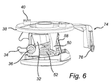
図1は、本発明の少なくとも1つの例示的な実施形態による吸入器2の組立分解図である。吸入器2は、全体的にディスク構造を有する用量投薬アセンブリ4、上側ハウジング部6、下側ハウジング部8、本実施形態ではマウスピース10の形態で示されている出口、および出口カバー12を備えている。
FIG. 1 is an exploded view of an inhaler 2 according to at least one exemplary embodiment of the present invention. The inhaler 2 comprises a dose dispensing assembly 4 having a generally disc structure, an upper housing part 6, a
用量投薬アセンブリ4は円形のベース14を備え、該ベースは、該ベースの円形延在部に沿って順次配置された複数のキャビティ16を有する。キャビティ16は、乾燥粉末形態などの医薬を配置することができ、ホイル部18によって密閉され、これにより密閉区画が形成されている。ホイル部18は、一般的なホイルの一部であるか、または分離したパッチとして設けられる。図示されている例では、ホイル部18を画定し、ベース14からの分離を容易にするためにミシン目が形成されている。各キャビティ16の上に、個々の関連する分離要素20が、ホイル部18の上側に取り付けられている。分離要素20は、任意の適切な種類の結合、溶接、接着などによって個々のホイル部18に取り付けられている。分離要素20の上方への移動または持ち上げにより、取り付けられたホイル部18がキャビティ16から分離されることになる。
The dose dispensing assembly 4 comprises a
円形ガイド構造22が、分離要素20の上に設けられている。ガイド構造22は、垂直に延在する壁によって分割された複数のガイドセクション24を備え、各ガイドセクション24は、それぞれの分離要素20に関連している。分離要素20がキャビティ保持ベース14から持ち上げられるときに、関連するガイドセクション24が、分離要素20の上方への移動を案内する。各ガイドセクション24は、板ばね26などの反作用要素を備えている。分離要素20が持ち上げられて板ばね26またはガイド構造22のいくつかの他の部分に衝突すると、音が発生される。分離要素20が持ち上げられて、開いたキャビティ16内の医薬が吸入気流に引き込まれ、分離要素20がベース14に戻った後に、板ばね26が、持ち上げられた分離要素20をベース14に接触した状態に維持してキャビティ16を覆う。これにより、残ったいかなる粉末も、覆われた使用済みキャビティ16から出るのが困難になるため、このような残った粉末が以降の吸入で引き込まれた場合に起こり得る用量のばらつきのリスクが低下する。また、残った粉末がキャビティ16から出て吸入器の機械の構成要素を故障させるリスク、または分離要素が使用者にとって不快であろうガタガタ音を発生させるリスクが低下する。円形ガイド構造22をガイドセクション24に分割する垂直壁は、要素を画定する側方流路として機能する。したがって、吸入気流は、ベース14のキャビティ領域に達すると横にそれるのが防止され、マウスピース10に案内される。代替案では、より低い垂直壁を有することができ、この場合は、隣接する分離要素20が、要素を画定する側方流路の機能を有することができる。
A
各分離要素20は、ベースの各キャビティ16に一致するベースカバー部28を備えている。加えて、各分離要素20は、中心に向かって延びた突出部30を有する。分離要素20を持ち上げるためのアクチュエータ32を備えた開放機構が設けられている。該アクチュエータは、本明細書では、分離要素20の中心に向かって延びた突出部30を保持するためのジョー34を備えた旋回可能なレバーの形態で表現されている。アクチュエータ32は、ジョー34が下がった位置にある付勢位置(図2および図6)と、ピボット軸36を中心に旋回した後の、ジョー34が上がった位置にある無負荷位置(図3および図7)を有する。ジョー34を備えたアクチュエータ32は、水平軸36を中心にのみ旋回可能であるため、吸入器2の操作中にマウスピース10の向きが維持される。
Each
図1に戻ると、全体的にディスク型のインサート38が、上側ハウジング部6の下側に設けられている。インサート38の上側は、2つのペグ40を備えている。ペグ40は、上側ハウジング部6の各弓状開口42を通って上方に延びており、出口カバー12に接続されている。出口カバー12が回転するときに、ペグ40は、弓状開口42を介して運動をインサート38に伝達し、インサート38も共に回転する。インサート38の下側は、本明細書ではカム44(図4を参照)の形態で例示されている第1の力伝達部材を備え、このカム44は、アクチュエータ32を無負荷位置から付勢位置に戻すために、回転動作を、アクチュエータ32のジョー34を作動させる直線状の力に変換する。カム44がアクチュエータ32のジョー34に接触すると(図5を参照)、アクチュエータ32は、分離要素20に向かって径方向に移動し、ピボット軸36を中心に回転する。また、ジョー34は、アクチュエータ32の準備位置または付勢位置まで下がる(図2を参照)。ジョー34の下降は、ジョー34を無負荷位置に持ち上げるように付勢するコイルばね46の力に逆らう。コイルばね46は、下側ハウジング部8から上方に突出するポスト48の周りに巻かれている。
Returning to FIG. 1, a generally disc-shaped
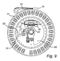
図4、図6、および図7に図示されているように、インサート38の下側は、コイルばね46の下側に位置し、かつ同じポスト48の周りのねじりばね52の端部に係合するように構成および適合された、突出した第2の力伝達部材50も備えている。ねじりばね52は、毎回、未開封のキャビティがマウスピース10に位置合わせされるように1回に1つの増分でキャビティ16を回転前進させるために駆動部材54に接続されている。該駆動部材は、図8、図9、図10、および図11に最も良く示されている。
As shown in FIGS. 4, 6, and 7, the underside of the
ラッチ56が、アクチュエータ32を付勢位置に維持するために設けられており、図2に明確に示されている。ラッチ56は、細長い支柱58で構成された第1の要素、およびフラップ60で構成された第2の要素を備えている。細長い支柱58は、マウスピース10の遠位側に位置するアクチュエータ32の端部近傍(マウスピース10に近位側にはジョー34が位置する)の第1の水平軸64を中心に旋回可能な第1の端部62を有する。細長い支柱58は、フラップ60によって支持されるように適合された第2の端部66を有する。フラップ60は、第2の水平軸68を中心に旋回可能である。該フラップは、下側ハウジング部8に設けられた多数の空気吸入口70(図1〜図3)を覆っている。空気は、使用者がマウスピース10(出口)から吸入するときに前記空気吸入口70を介して吸入器2に進入することができる。
A
図2は、吸入器の選択された細部の断面図であり、吸入器は、準備状態である、すなわちアクチュエータ32が付勢位置にラッチされている。したがって、アクチュエータ32のジョー34が、コイルばね46の力に逆らって下げられていて、ここでは、マウスピースに位置合わせされた分離要素20の中心に延びた突出部30を包囲している。細長い支柱58の第2の端部66は、フラップ60の嵌め合い部によって支持されている。支柱58およびフラップ60を含むラッチ56は、ここでは、アクチュエータ32を付勢位置にラッチする第1の位置にある。ラッチ56は、第1の位置に向かって付勢されている。より具体的には、この例示的な実施形態では、細長い支柱58の第2の端部66とフラップ60との間の接合面または接触点が、空気吸入口70を覆うフラップ60の部分と同様に第2の水平軸68の同じ側に位置している(図2では、細長い支柱58とフラップとの間の接触点は、第2の水平軸68の左側に位置する)。したがって、細長い支柱58によって画定されるフラップ60の質量および力の中心が、第2の水平軸68によって画定されるピボット点の左側(図2)に位置するため、フラップ60が、図示されている低い位置に維持される。フラップ60が静止したままであれば、支柱58の移動も防止されるため、アクチュエータ32が付勢位置にラッチされて維持される。フラップ60に加えられる力は、適切には、使用者の吸入が上回り得る気流閾値に一致するように調整されている。位置維持要素72が、支柱58の第1の端部62に設けられている。上記から、位置維持要素72は、ディスク型インサート38(図1)に接触する。この接触は、使用者が出口カバー12を閉じる際に異なる向き(例えば、上下逆)に吸入器を回した場合に、支柱58が、第1の水平軸64を中心に誤って旋回しないようにしている。したがって、フラップ60および支柱58は、使用者が出口カバー12を閉じる際に吸入器を上下逆さに保持したとしても、アクチュエータ32をラッチすることができる。
FIG. 2 is a cross-sectional view of selected details of the inhaler, where the inhaler is ready, ie, the
少なくとも1つの他の実施形態では、図示されている位置維持要素72は、むしろ付勢ばね要素72として機能することができる。このような実施形態では、付勢ばね要素72は、ディスク型インサート38(図1)に接触しているだけではなく、ディスク型インサート38によって実際に下方に押圧され得る。付勢ばね要素72に加えられるこの力は、第1の軸64を中心とするてこ作用を有することができ、支柱58の第2の端部66をジョー34およびマウスピースに向かう方向(図2では時計回りの回転)に作動する。フラップ60の嵌め合い部に接触している第2の端部66のこの付勢が、フラップ60を図示されている実質的に水平な低い位置に付勢された状態に維持することができる。付勢ばね要素72からフラップ60に伝達される付勢力は、適切には、使用者の吸入が上回り得る気流閾値に一致するように調整することができる。
In at least one other embodiment, the illustrated
(図面には示されていない)別の実施形態では、前記要素72は、インサート38に配置されるばねによって置き換えることができる。該ばねは、例えば、前記要素72と本質的に同じ方法で支柱58の上部の小さい突出部を付勢するためにこの突出部に支持される鋼ばねとすることができる。
In another embodiment (not shown in the drawings), the
1回分を投与するためには、使用者の吸入が、十分な気流を発生させて、付勢力に対してフラップ60を持ち上げる。これは、図3に図示されている。フラップ60が気流によって持ち上げられて第2の軸68を中心に旋回すると(図3では時計回り)、この軸の反対側にあるフラップ60の嵌め合い部が下げられるため、支柱58の第2の端部66がその支持を失う。これにより、支柱58が第1の軸64を中心に旋回し(図3では反時計回り)、フラップ60の嵌め合い部から「回転して」外れる。このとき、ラッチ56はその第2の位置にあり、アクチュエータ32が前記無負荷位置に移動することができる。したがって、コイルばね46に蓄積されたエネルギーが、ここで、解放されたアクチュエータ32を移動させる。アクチュエータ32は、その軸36を中心に旋回し、ジョー34が持ち上げられるため、係合した分離要素20がベース14から持ち上げられる。ホイル部18は、分離要素20に取り付けられたままであるため、医薬を含むキャビティ16が開く。図1は、アクチュエータ32のジョー34によって持ち上げられる分離要素20を一点鎖線で図示している。
To administer a single dose, the user's inhalation generates sufficient airflow to lift the
例示的な吸入器2のデザインにより、キャビティ16内で粉末が分散し、粉末がキャビティ16から排出される際に、せん断駆動キャビティの原理と称される現象を利用できることに留意されたい。せん断駆動キャビティは、上側の境界が望ましい流れの方向に移動するため、キャビティ内で回転が起こる、キャビティ内での流れのモデルである。図2は、粉末の上に適切な上部空間を有する医薬粉末を含むキャビティ16を図示している。図3では、吸入気流が、平坦な表面領域に沿って前記上部空間の近傍を通り、前記平坦な表面領域が、粉末を含むキャビティ16に開口している。吸入気流の水平通過により、キャビティ16内に渦気流を形成し、これにより粉末が分散されてキャビティ16から排出される。キャビティ16は、全体的にれんが型であり、キャビティ開口はリムを有し、該リムにおいて、キャビティの側面が流路の平坦な表面領域内へ乗り越える。したがって、気流が、流路にあるキャビティを通過する際に、流路にあるキャビティ開口のリムに一致する平面と平行に流れるのが好ましい。
Note that the exemplary inhaler 2 design allows the phenomenon referred to as the principle of shear driven cavities to be utilized when the powder is dispersed within the
フラップ60は、1回分が投薬された後に低い位置に戻ることができるが、アクチュエータ32のジョー34は、使用者が次の服用のために吸入器を準備するまで無負荷位置(図7を参照)に維持される。
The
吸入器2の準備は、出口カバー12の開放または閉鎖のいずれかに結びつけることができるが、この例示的な実施形態では、出口カバー12の閉鎖が吸入器2を準備するものとする。上述のように、使用者が1回分を吸入すると(図3および図7)、使用者は、出口カバー12を閉じてマウスピース10(図1)を覆う。出口カバー12は、直線状または段階的通路などの様々な通路を形成するようにデザインすることができるが、この例示的な実施形態では、出口カバー12は、回転してマウスピース10を覆う。出口カバー12をこのように閉じる際に、力伝達突出部材50とカム44とを備える接続されたインサート38が、アクチュエータ32のジョー34をコイルばね46(図5)の力に逆らって押し下げ、ベース14を回転させ、これにより未開封の次のキャビティ16がジョー34に差し出される。インサート38はまた、支柱58の位置維持要素72も押圧するため、ラッチ56が第1の位置に戻り、このためアクチュエータ32がジョー34を持ち上げることができない。次いで、別の1回分を服用するために使用者が出口カバー12を開けると、ラッチされて付勢されたアクチュエータ32を作動させずに、インサート38が反対方向に回転する。吸入器2は、使用者がマウスピース10を介して呼吸すると、ここで準備(始動)されて投与準備完了となり、呼吸をトリガとしてホイル部18をキャビティ16から持ち上げることが可能となる。
Although preparation of the inhaler 2 can be tied to either opening or closing of the
未開封のキャビティ16に位置合わせされないでアクチュエータ32が付勢位置にラッチされるリスクを低減するために、ラッチ56は、次のキャビティがマウスピース10に位置合わせされるまで第1のラッチ位置に戻ることができない。また、オーバーインデックスのリスク、すなわち未開封のキャビティ16が開封されずにマウスピース10を通過するリスクを低減するために、キャビティをマウスピース10に順次位置合わせするためのインデックス機構が設けられており、該インデックス機構は、アクチュエータ32が無負荷位置から付勢位置に移動した後、次のキャビティ16をマウスピース10に位置合わせするように適合されている。
In order to reduce the risk of the
上述のように、図示されている例示的な実施形態では、1回分が投薬された後、使用者が出口カバー12を閉じる。上記されているように、出口カバー12の回転により、全体的にディスク型のインサート38が回転する。このインサート38の回転により、前記のように設けられたカム44が、アクチュエータ32(図5を参照)をその付勢位置に移動させる。したがって、アクチュエータ32のジョー34は、図3および図7に図示されている高い無負荷位置から、図2および図6に図示されている低い付勢位置に移動する。
As described above, in the illustrated exemplary embodiment, the user closes the
インサート38の回転により、カム44がアクチュエータ32を作動させるのと実質的に同時に、突出した第2の力伝達部材50が、インデックス機構を作動させて次のキャビティ16を前進させ、マウスピース10に位置合わせする。より具体的には、図6に図示されているように、突出部材50が、駆動部材54(図8を参照)に接続されたねじりばね52を付勢する。付勢されたねじりばね52は、接続された駆動部材54をポスト48(図1を参照)によって画定された中心軸を中心に回転させてベース14に係合させ、これによりベース14が回転して次のキャビティ16がマウスピースに位置合わせする。
At substantially the same time as the
しかし、ねじりばね52を介して突出部材50によって加えられる駆動部材54に対する力が、少なくともアクチュエータ32がその付勢位置に達するまで一時的に反作用する。アクチュエータ32のジョー34が、インデックスまでに下がらないと、分離要素20が次に、インデックスの際にジョー34に衝突するリスクがあるであろう。
However, the force on the
前記反作用部材は、区画が移動するのを防止するように適合されたブレーキ74を備えている。ブレーキ74は、下側ハウジング部8から突出した外側ポスト75(図1を参照)に取り付けられている。該ブレーキは、ベース14の外周面に対して押圧されるブレーキパッド76(図9を参照)を備え、これによりベース14の回転を防止する。反作用部材はまた、全体的にディスク型のインサート38の下側に設けられたトラック80内を移動する、ブレーキ74に接続された従動節78(図1および図11を参照)も備えている。トラック80は、図4、図5、および図11に最も良く示されており、図11は、従動節78がトラック80内をどのように移動するかを明示している。したがって、従動節78がトラック80内を移動するときは、従動節78は、不規則な通路に従い、解放点に達すると、接続されたブレーキ74がベース14を解放する(図10を参照)。ここで、ベース14は、既に説明したようにねじりばね52によって作動される駆動部材54によって回転可能となる。したがって、上に例示した機械式連続アセンブリは、開放機構(本明細書では、ジョーが付いたアクチュエータ32として例示)の付勢と区画(本明細書では、ベース14の密閉キャビティ16として例示)のインデックスを交互に行う。
The reaction member includes a
図9に図示されているように、ブレーキ74が解放されるまで、駆動部材54の端部が、ベース14の複数の歯82の1つに係合している。アーム型キャッチ84が、駆動部材54に接続されているが、アーム型キャッチ84は、駆動部材54と一体形成しても良い。キャッチ84は、ラッチ56の第1の要素(支柱58)がラッチ56の第2の要素(フラップ60)によって支持されるのを防止する防止位置にある。したがって吸入器のこの状態では、アクチュエータは、付勢位置にラッチされ得ない。したがって、同じキャビティ16からの再投与のリスクが低下する。
As shown in FIG. 9, the end of the
ブレーキ74が解放されると、駆動部材54が、係合した歯82によってベース14を1キャビティ段階回転させる。図9および図10はまた、前記駆動部材のピボット点(点線で示されている)で旋回可能に取り付けられた爪86も図示している。図9では、爪86は、引き込まれているが、図10では、爪86は、前進して歯82に係合し、本明細書では駆動部材54によって押された同じ歯82の反対側に係合するとして例示されている。爪86は、駆動部材54がベース14を過度に回転するのを防止し、吸入器が、一度に1キャビティ段階のみで確実にインデックスされるようにしている。
When the
駆動部材54およびキャッチ84は、下側ハウジング部8から上方に突出した中心ポスト48(図1)を中心に旋回する共通バレル88(図11に最も良く示されている)に接続されている。駆動部材54がベース14を回転させると、図10に図示されているようにキャッチ84が防止位置から移動するため、支柱58がフラップ60によって支持されるようになり、付勢されたアクチュエータがラッチされるのを可能とする。このとき、吸入器は準備された状態となっている。
The
上述したように、特に図2および図3に関連して、使用者が出口カバー12を開けて、マウスピース10を介して吸入すると、フラップ60が持ち上げられて支柱58がフラップ60から外れ、これによりアクチュエータ32のラッチが解除される。コイルばね46によって付勢されているアクチュエータ32が持ち上げられて、アクチュエータ32のジョー34が、ここではマウスピース10に位置合わせされているキャビティ16から分離要素20およびホイル部18を引き離す。図11から分かるように、可動引張りアーム90が、駆動部材54とアクチュエータ32を接続している。アクチュエータ32およびジョー34が持ち上げられると、引張りアーム90がその動きに従うため、引張りアーム90の他端で、駆動部材54が、図10に示されている準備状態から図9に示されている投与状態に引っ張られる。結果として、キャッチ84が、図9に示されている防止位置に戻る。次に、使用者が出口カバー12を閉じると、吸入器が再び準備状態になる。
As described above, particularly with reference to FIGS. 2 and 3, when the user opens the
使用者が、何らかの理由で出口カバー12を十分に閉じないと、トラック80内を移動する従動節78が解放点に達しないため、ブレーキ74が解除されない。すなわち、インデックスされないことになる。さらに、アクチュエータ32は、その付勢位置にあるが、既に述べたように、ラッチはインデックスに関連してのみ行うことができるため、アクチュエータ32はラッチされない。したがって、使用者が、次に、完全に閉じられなかった出口カバー12を開いても、アクチュエータ32は、単にその無負荷位置に戻るだけである。
If the user does not sufficiently close the
本明細書で説明したインデックス機構は、一方向に限定されたベース14の回転を可能にする。したがって、インデックス解除は起こりえない。これは、他の種類の開放機構または分離要素に関しても有利であろう。 The indexing mechanism described herein allows for the rotation of the base 14 limited to one direction. Therefore, de-indexing cannot occur. This may also be advantageous with respect to other types of opening mechanisms or separating elements.
本願では、「上側」、「下側」、「上に」、「下に」などの用語は、吸入器が周囲環境内でどのように向けられているかにかかわらず、吸入器の要素間の内部の関係を記載するために説明目的で使用されていることに留意されたい。例えば、図面の例示的な実施形態では、使用者により吸入器2全体がどのように保持または回転されるかにかかわらず、キャビティ16は、ホイル部18の「下に」配置されていると見なされ、分離要素20は、ホイル部18の「上に」配置されていると見なされる。同様に、「水平に」は、ホイル部18の平面またはホイル部18の平面に平行な任意の平面に位置する方向を意味し、「垂直に」は、このような平面に直交する任意の方向を意味する。したがって、垂直線は、キャビティ16、ホイル部18、および分離要素20と交差し得る。
In this application, the terms “upper”, “lower”, “up”, “down”, etc. refer to the elements of the inhaler, regardless of how the inhaler is oriented in the surrounding environment. Note that it is used for illustrative purposes to describe internal relationships. For example, in the exemplary embodiment of the drawings, the
ベース14、分離要素20、アクチュエータ32、およびラッチ56などの吸入器2のほとんどの構成要素は、適切には、ポリマーなどのプラスチック材料から形成されるが、金属またはセラミックなどの他の材料も考えられ得る代替材料である。
Most components of the inhaler 2 such as the
吸入器2は、適切には、例えば、国際出願第2006/000758号に記載されている吸湿シンクまたは乾燥剤を含む任意の他の適当な代替物などの湿気防止を与える構造を含むことができる。 The inhaler 2 may suitably include a structure that provides moisture protection, such as, for example, a moisture absorption sink or any other suitable alternative that includes a desiccant as described in International Application No. 2006/000758. .
(図面には示されていない)さらなる実施形態では、前記カバー12に代えて、ハウジングの大部分にわたって延在し、かつマウスピースが露出される開放構造とマウスピースおよびハウジングの大部分がカバー内に閉じ込められた閉鎖構造とを有するカバーを用いてもよい。該カバーは、前の実施形態ではインサート38に関連し、該カバーの内面に形成されたカム表面を有することができる。ハウジング内の機構の対応する部品に係合するために、一部またはすべてのカム表面が突出可能な開口をハウジングに設けることができる。
In a further embodiment (not shown in the drawing), instead of the
Claims (15)
2つの面を有し、一方の面が前記キャビティに取り付けられ、該キャビティを気密シールするホイル部と、
該ホイル部を前記キャビティから分離するために前記ホイル部の他方の面に取り付けられた分離要素と、
該分離要素に係合可能なアクチュエータであって、無負荷位置に向かって付勢される付勢位置を有し、該付勢位置から前記無負荷位置への移動の際に、前記分離要素を前記キャビティから分離させる、アクチュエータと、
該アクチュエータを前記付勢位置にラッチする第1の位置と前記アクチュエータが前記無負荷位置になることを可能にする第2の位置とを有するラッチであって、流路を通る吸入流が前記ラッチを前記第1の位置から前記第2の位置に移動させるように少なくとも部分的に前記流路に配置されている、ラッチと、
を備える、吸入器。 A base having at least one sealed cavity containing a medicament;
A foil portion having two surfaces, one surface being attached to the cavity and hermetically sealing the cavity;
A separation element attached to the other side of the foil portion to separate the foil portion from the cavity;
An actuator that can be engaged with the separation element, and has an urging position that is urged toward the no-load position, and the separation element is moved during the movement from the urging position to the no-load position. An actuator to be separated from the cavity;
A latch having a first position for latching the actuator in the biased position and a second position allowing the actuator to be in the no-load position, wherein suction flow through a flow path is latched; A latch disposed at least partially in the flow path so as to move the first position from the first position to the second position;
An inhaler.
前記係合部は、前記無負荷位置にあるときよりも前記付勢位置にあるときの方が前記キャビティに近接する、請求項1に記載の吸入器。 The actuator includes a pivotable lever having an engagement portion that temporarily engages the separation element;
The inhaler according to claim 1, wherein the engagement portion is closer to the cavity when in the biased position than when in the unloaded position.
該出口の閉鎖と開放を交互に行うために移動可能な出口カバーと、
該出口カバーに接続されたプッシャと、を備え、
前記出口カバーの前記閉鎖動作および前記開放動作のいずれか一方が行なわれると、前記接続されたプッシャが、前記アクチュエータを前記無負荷位置から前記付勢位置に押すように移動する、請求項1〜3のいずれか一項に記載の吸入器。 An outlet, such as a mouthpiece or nasal adapter,
An exit cover movable to alternately close and open the outlet;
A pusher connected to the outlet cover,
2. When one of the closing operation and the opening operation of the outlet cover is performed, the connected pusher moves to push the actuator from the no-load position to the biasing position. The inhaler according to any one of 3 above.
前記第1の要素は前記アクチュエータに接続され、
前記第2の要素は、前記第1の要素を固定して前記アクチュエータが前記無負荷位置に移動するのを防止する支持位置と、前記第1の要素が移動できることにより、前記付勢されたアクチュエータが前記無負荷位置に移動することができる非支持位置と、を有し、
前記第2の要素は、前記吸入流に応答して前記非支持位置まで移動可能である、請求項6に記載の吸入器。 The latch comprises a first element and a second element;
The first element is connected to the actuator;
The second element includes a support position that fixes the first element and prevents the actuator from moving to the no-load position, and the biased actuator is configured such that the first element can move. An unsupported position capable of moving to the unloaded position,
The inhaler according to claim 6, wherein the second element is movable to the unsupported position in response to the inhalation flow.
前記第2の要素は、前記吸入流に応答して、前記支柱が支持された状態から外れることができるように旋回する、請求項7または8に記載の吸入器。 The second element is pivotable about an axis;
9. An inhaler according to claim 7 or 8, wherein the second element pivots in response to the inhalation flow so that the strut can be removed from a supported state.
モメタゾン、臭化イプラトロピウム、チオトロピウムおよびその塩、サルメテロール、プロピオン酸フルチカゾン、ジプロピオン酸ベクロメタゾン、レプロテロール、クレンブテロール、ロフレポニドおよび塩、ネドクロミル、クロモグリク酸ナトリウム、フルニソリド、ブデソニド、フマル酸ホルモテロール二水和物、テルブタリン、硫酸テルブタリン、サルブタモール塩基および硫酸サルブタモール、フェノテロール、3−[2−(4−ヒドロキシ−2−オキソ−3H−1,3−ベンゾチアゾール−7−イル)エチルアミノ]−N−[2−[2−(4−メチルフェニル)エトキシ]エチル]プロパン−スルホンアミド、塩酸塩、インダカテロール、臭化アクリジニウム、N−[2−(ジエチルアミノ)エチル]−N−(2−{[2−(4−ヒドロキシ−2−オキソ−2,3−ジヒドロ−1,3−ベンソチアゾール−7−イル)エチル]アミノ}エチル)−3−[2−(1−ナフチル)エトキシ]プロパンアミド、またはその薬学的に許容され得る塩(例えば、二臭化水素酸塩)、
N−シクロヘキシル−N3−[2−(3−フルオロフェニル)エチル]−N−(2−{[2−(4−ヒドロキシ−2−オキソ−2,3−ジヒドロ−1,3−ベンゾチアゾール−7−イル)エチル]アミノ}エチル)−β−アラニンアミド、またはその薬学的に許容され得る塩(例えば、ジ−D−マンデル酸)、
[2−(4−クロロ−ベンジルオキシ)−エチル]−[2−((R)−シクロヘキシル−ヒドロキシ−フェニル−メチル)−オキサゾール−5−イルメチル]−ジメチル−アンモニウム塩(例えば、ヘミ−ナフタレン−1,5−ジスルホン酸塩)、
(R)−1−[2−(4−フルオロ−フェニル)−エチル]−3−((S)−2−フェニル−2−ピペリジン−1−イル−プロピオニルオキシ)−1−アゾニア−ビシクロ[2.2.2]オクタン塩(例えば、臭化物またはトルエンスルホン酸塩)、或いは、
これらのいずれか2つ以上の組み合わせから選択される活性成分を含む、請求項1〜11のいずれか一項に記載の吸入器。 The medicament is
Mometasone, ipratropium bromide, tiotropium and its salts, salmeterol, fluticasone propionate, beclomethasone dipropionate, reproterol, clenbuterol, rofleponide and salts, nedocromil, cromoglycate sodium, flunisolide, budesonide, formoterol fumarate diformate, Terbutaline sulfate, salbutamol base and salbutamol sulfate, fenoterol, 3- [2- (4-hydroxy-2-oxo-3H-1,3-benzothiazol-7-yl) ethylamino] -N- [2- [2- (4-Methylphenyl) ethoxy] ethyl] propane-sulfonamide, hydrochloride, indacaterol, acridinium bromide, N- [2- (diethylamino) ethyl] -N- (2-{[2- (4 Hydroxy-2-oxo-2,3-dihydro-1,3-benzothiazol-7-yl) ethyl] amino} ethyl) -3- [2- (1-naphthyl) ethoxy] propanamide, or a pharmaceutical thereof Acceptable salts (eg dihydrobromide),
N- Cyclohexyl -N 3 - [2- (3- fluorophenyl) ethyl] -N- (2 - {[2- (4- hydroxy-2-oxo-2,3-dihydro-1,3-benzothiazole - 7-yl) ethyl] amino} ethyl) -β-alaninamide, or a pharmaceutically acceptable salt thereof (eg, di-D-mandelic acid),
[2- (4-Chloro-benzyloxy) -ethyl]-[2-((R) -cyclohexyl-hydroxy-phenyl-methyl) -oxazol-5-ylmethyl] -dimethyl-ammonium salt (eg hemi-naphthalene- 1,5-disulfonate)
(R) -1- [2- (4-Fluoro-phenyl) -ethyl] -3-((S) -2-phenyl-2-piperidin-1-yl-propionyloxy) -1-azonia-bicyclo [2 2.2] octane salt (eg, bromide or toluene sulfonate), or
The inhaler according to any one of claims 1 to 11, comprising an active ingredient selected from a combination of any two or more thereof.
前記密閉キャビティの開封が行われるように前記吸入器を介して気流を供給するステップと、
前記気流に応答して、少なくとも前記キャビティの開口に一致している前記ホイルの部分を分離することによって前記密閉キャビティを開封するステップと、
前記気流に引き込まれた医薬を投与するステップと、
を含む、方法。 A method of administering a medicament from a sealed cavity in an inhaler hermetically sealed by a foil, comprising:
Supplying an airflow through the inhaler so that the sealed cavity is opened;
Opening the sealed cavity in response to the air flow by separating at least a portion of the foil that coincides with an opening in the cavity;
Administering a medicament drawn into the air stream;
Including a method.
Applications Claiming Priority (3)
| Application Number | Priority Date | Filing Date | Title |
|---|---|---|---|
| US10360608P | 2008-10-08 | 2008-10-08 | |
| US61/103,606 | 2008-10-08 | ||
| PCT/SE2009/051110 WO2010042033A1 (en) | 2008-10-08 | 2009-10-07 | Inhalation device and method of dispensing medicament |
Publications (3)
| Publication Number | Publication Date |
|---|---|
| JP2012505017A true JP2012505017A (en) | 2012-03-01 |
| JP2012505017A5 JP2012505017A5 (en) | 2012-11-29 |
| JP5518082B2 JP5518082B2 (en) | 2014-06-11 |
Family
ID=42100804
Family Applications (1)
| Application Number | Title | Priority Date | Filing Date |
|---|---|---|---|
| JP2011530993A Expired - Fee Related JP5518082B2 (en) | 2008-10-08 | 2009-10-07 | Inhalation device and method of administering a medicament |
Country Status (17)
| Country | Link |
|---|---|
| US (1) | US9095670B2 (en) |
| EP (1) | EP2334358B1 (en) |
| JP (1) | JP5518082B2 (en) |
| KR (1) | KR20110074766A (en) |
| CN (1) | CN102245239B (en) |
| AU (1) | AU2009302956B8 (en) |
| BR (1) | BRPI0920658A2 (en) |
| CA (1) | CA2738822A1 (en) |
| CL (1) | CL2011000789A1 (en) |
| EA (1) | EA019293B1 (en) |
| ES (1) | ES2579902T3 (en) |
| IL (1) | IL212074A0 (en) |
| MX (1) | MX2011003759A (en) |
| NZ (1) | NZ591956A (en) |
| UA (1) | UA101056C2 (en) |
| WO (1) | WO2010042033A1 (en) |
| ZA (1) | ZA201103334B (en) |
Families Citing this family (16)
| Publication number | Priority date | Publication date | Assignee | Title |
|---|---|---|---|---|
| DE102005057685A1 (en) * | 2005-12-01 | 2007-06-06 | Boehringer Ingelheim Pharma Gmbh & Co. Kg | Inhaler and storage for a dry drug formulation and methods and use thereof |
| US9889087B2 (en) * | 2014-06-10 | 2018-02-13 | The Board Of Trustees Of The Leland Stanford Junior University | Intranasal delivery of β2-adrenergic receptor agonists for improving cognition in humans with down syndrome and compositions therefor |
| AR106018A1 (en) | 2015-08-26 | 2017-12-06 | Achillion Pharmaceuticals Inc | ARYL, HETEROARYL AND HETEROCYCLIC COMPOUNDS FOR THE TREATMENT OF MEDICAL DISORDERS |
| EP3340982B1 (en) | 2015-08-26 | 2021-12-15 | Achillion Pharmaceuticals, Inc. | Compounds for treatment of immune and inflammatory disorders |
| CA3029262A1 (en) | 2016-06-27 | 2018-01-04 | Achillion Pharmaceuticals, Inc. | Quinazoline and indole compounds to treat medical disorders |
| GB2553534A (en) * | 2016-09-07 | 2018-03-14 | 3M Innovative Properties Co | Trigger mechanism for an inhaler |
| GB201615186D0 (en) * | 2016-09-07 | 2016-10-19 | 3M Innovative Properties Co | Energy storage mechanism for an inhaler |
| EP3595758B1 (en) | 2017-03-15 | 2021-09-29 | CSP Technologies, Inc. | Inhaler |
| CN110271772B (en) * | 2018-03-13 | 2023-09-15 | 李和伟 | Drug administration device |
| US20230022157A1 (en) | 2018-08-20 | 2023-01-26 | Achillion Pharmaceuticals, Inc. | Pharmaceutical compounds for the treatment of complement factor d medical disorders |
| EP3866773A4 (en) | 2018-10-16 | 2022-10-26 | Georgia State University Research Foundation, Inc. | Carbon monoxide prodrugs for the treatment of medical disorders |
| US11419397B2 (en) | 2019-01-22 | 2022-08-23 | Coopervision International Limited | Push-up contact lens blister package |
| US11267643B2 (en) | 2019-01-22 | 2022-03-08 | Coopervision International Limited | Contact lens dispenser |
| US11136176B2 (en) | 2019-01-22 | 2021-10-05 | Coopervision International Limited | Contact lens blister package with lens cradle |
| US11229266B2 (en) | 2019-01-22 | 2022-01-25 | Coopervision International Limited | Tessellating blister packages for contact lenses |
| US11253035B2 (en) | 2019-01-22 | 2022-02-22 | Coopervision International Holding Company, Lp | Blister package for contact lens |
Citations (7)
| Publication number | Priority date | Publication date | Assignee | Title |
|---|---|---|---|---|
| JPH06502095A (en) * | 1990-11-14 | 1994-03-10 | ミネソタ マイニング アンド マニュファクチャリング カンパニー | inhalation device |
| JPH09504455A (en) * | 1993-10-26 | 1997-05-06 | テナックス コーポレーション | Dry powder drug inhaler |
| JP2000503565A (en) * | 1996-01-03 | 2000-03-28 | グラクソ、グループ、リミテッド | Inhaler |
| JP2001511402A (en) * | 1997-03-25 | 2001-08-14 | イノベーティブ・ディバイシィーズ・エルエルシー | Dry powder drug inhaler with inhalation activated flow splitting means to trigger drug delivery |
| JP2002537952A (en) * | 1999-03-10 | 2002-11-12 | グラクソ グループ リミテッド | Improvements on inhalation devices |
| JP2005502440A (en) * | 2001-09-19 | 2005-01-27 | アドヴェント ファーマセウティカルズ プロプライエタリー リミテッド | Inhaler |
| JP2008540264A (en) * | 2005-05-02 | 2008-11-20 | アストラゼネカ・アクチエボラーグ | Configuration and method for opening a cavity, drug package and distribution device |
Family Cites Families (21)
| Publication number | Priority date | Publication date | Assignee | Title |
|---|---|---|---|---|
| EP1042025B1 (en) | 1997-12-02 | 2009-06-03 | Valois SAS | Dry powder inhaler |
| NL1008031C2 (en) | 1998-01-15 | 1999-07-21 | Pharmachemie Bv | Device for inhaling medicament. |
| EP1220698B1 (en) | 1999-10-12 | 2004-07-21 | SHL Medical AB | Inhaler |
| US7171965B2 (en) | 2000-02-01 | 2007-02-06 | Valois S.A.S. | Breath actuated dry powder inhaler and tape dose strip |
| WO2001072605A1 (en) | 2000-03-27 | 2001-10-04 | Dura Pharmaceuticals, Inc. | Containers for individual doses of an inhalable pharmaceutical |
| SE517227C2 (en) | 2000-09-25 | 2002-05-14 | Microdrug Ag | Dry powder inhaler with foil cutter |
| GB0120018D0 (en) * | 2001-08-16 | 2001-10-10 | Meridica Ltd | Pack containing medicament and dispensing device |
| US6941947B2 (en) | 2002-12-18 | 2005-09-13 | Quadrant Technologies Limited | Unit dose dry powder inhaler |
| GB0315509D0 (en) | 2003-07-02 | 2003-08-06 | Meridica Ltd | Dispensing device |
| GB0322544D0 (en) * | 2003-09-26 | 2003-10-29 | Innovata Biomed Ltd | Apparatus |
| SE0401654D0 (en) | 2004-06-24 | 2004-06-24 | Astrazeneca Ab | A support structure for a drug |
| GB0426780D0 (en) * | 2004-12-07 | 2005-01-12 | 3M Innovative Properties Co | Pressurized inhalation devices |
| JP2009543860A (en) | 2006-07-19 | 2009-12-10 | アストラゼネカ・アクチエボラーグ | Novel tricyclic spiropiperidine compounds, their synthesis and their use as chemokine receptor activity modulators |
| WO2008101992A1 (en) * | 2007-02-21 | 2008-08-28 | Novo Nordisk A/S | Aerosol generating device with air flow control |
| GB0704928D0 (en) | 2007-03-14 | 2007-04-25 | Cambridge Consultants | Dry powder inhalers |
| HUE034380T2 (en) * | 2007-04-30 | 2018-02-28 | Sun Pharma Advanced Res Co Ltd | Inhalation device |
| WO2009008832A1 (en) | 2007-07-12 | 2009-01-15 | Astrazeneca Ab | Medicament containing structure, method and inhalation device comprising such structure |
| US8393322B2 (en) * | 2008-02-12 | 2013-03-12 | Astrazeneca Ab | Inhaler comprising a base having a plurality of medicament containing sealed cavities |
| MX2010007882A (en) * | 2008-02-12 | 2010-08-06 | Astrazeneca Ab | Inhaler comprising a base having at least one sealed cavity containing medicament. |
| JP5512686B2 (en) * | 2008-10-08 | 2014-06-04 | アストラゼネカ・アクチエボラーグ | Breath-actuated inhaler |
| JP5841429B2 (en) * | 2008-10-08 | 2016-01-13 | アストラゼネカ・アクチエボラーグAstrazeneca Aktiebolag | Inhaler with audible indicator means |
-
2009
- 2009-10-07 ES ES09819487.1T patent/ES2579902T3/en active Active
- 2009-10-07 US US13/129,393 patent/US9095670B2/en not_active Expired - Fee Related
- 2009-10-07 CN CN2009801491192A patent/CN102245239B/en not_active Expired - Fee Related
- 2009-10-07 UA UAA201103725A patent/UA101056C2/en unknown
- 2009-10-07 AU AU2009302956A patent/AU2009302956B8/en not_active Ceased
- 2009-10-07 BR BRPI0920658A patent/BRPI0920658A2/en not_active IP Right Cessation
- 2009-10-07 MX MX2011003759A patent/MX2011003759A/en not_active Application Discontinuation
- 2009-10-07 JP JP2011530993A patent/JP5518082B2/en not_active Expired - Fee Related
- 2009-10-07 CA CA2738822A patent/CA2738822A1/en not_active Abandoned
- 2009-10-07 EP EP09819487.1A patent/EP2334358B1/en not_active Not-in-force
- 2009-10-07 EA EA201100487A patent/EA019293B1/en not_active IP Right Cessation
- 2009-10-07 KR KR1020117010404A patent/KR20110074766A/en not_active Application Discontinuation
- 2009-10-07 NZ NZ591956A patent/NZ591956A/en not_active IP Right Cessation
- 2009-10-07 WO PCT/SE2009/051110 patent/WO2010042033A1/en active Application Filing
-
2011
- 2011-03-31 IL IL212074A patent/IL212074A0/en unknown
- 2011-04-08 CL CL2011000789A patent/CL2011000789A1/en unknown
- 2011-05-06 ZA ZA2011/03334A patent/ZA201103334B/en unknown
Patent Citations (7)
| Publication number | Priority date | Publication date | Assignee | Title |
|---|---|---|---|---|
| JPH06502095A (en) * | 1990-11-14 | 1994-03-10 | ミネソタ マイニング アンド マニュファクチャリング カンパニー | inhalation device |
| JPH09504455A (en) * | 1993-10-26 | 1997-05-06 | テナックス コーポレーション | Dry powder drug inhaler |
| JP2000503565A (en) * | 1996-01-03 | 2000-03-28 | グラクソ、グループ、リミテッド | Inhaler |
| JP2001511402A (en) * | 1997-03-25 | 2001-08-14 | イノベーティブ・ディバイシィーズ・エルエルシー | Dry powder drug inhaler with inhalation activated flow splitting means to trigger drug delivery |
| JP2002537952A (en) * | 1999-03-10 | 2002-11-12 | グラクソ グループ リミテッド | Improvements on inhalation devices |
| JP2005502440A (en) * | 2001-09-19 | 2005-01-27 | アドヴェント ファーマセウティカルズ プロプライエタリー リミテッド | Inhaler |
| JP2008540264A (en) * | 2005-05-02 | 2008-11-20 | アストラゼネカ・アクチエボラーグ | Configuration and method for opening a cavity, drug package and distribution device |
Also Published As
| Publication number | Publication date |
|---|---|
| US9095670B2 (en) | 2015-08-04 |
| EP2334358A1 (en) | 2011-06-22 |
| CN102245239A (en) | 2011-11-16 |
| UA101056C2 (en) | 2013-02-25 |
| JP5518082B2 (en) | 2014-06-11 |
| NZ591956A (en) | 2012-11-30 |
| US20120125330A1 (en) | 2012-05-24 |
| WO2010042033A1 (en) | 2010-04-15 |
| ES2579902T3 (en) | 2016-08-17 |
| CL2011000789A1 (en) | 2011-10-21 |
| CA2738822A1 (en) | 2010-04-15 |
| EA201100487A1 (en) | 2011-12-30 |
| BRPI0920658A2 (en) | 2016-01-12 |
| AU2009302956B2 (en) | 2012-09-13 |
| CN102245239B (en) | 2013-08-14 |
| KR20110074766A (en) | 2011-07-01 |
| EP2334358A4 (en) | 2014-04-02 |
| EP2334358B1 (en) | 2016-02-10 |
| AU2009302956A1 (en) | 2010-04-15 |
| AU2009302956B8 (en) | 2012-09-27 |
| IL212074A0 (en) | 2011-06-30 |
| ZA201103334B (en) | 2012-01-25 |
| MX2011003759A (en) | 2011-05-03 |
| EA019293B1 (en) | 2014-02-28 |
Similar Documents
| Publication | Publication Date | Title |
|---|---|---|
| JP5518082B2 (en) | Inhalation device and method of administering a medicament | |
| JP5841429B2 (en) | Inhaler with audible indicator means | |
| JP5512686B2 (en) | Breath-actuated inhaler | |
| JP5632848B2 (en) | Inhaler for indexing linked to the movement of the cover | |
| EP2595684A1 (en) | Inhaler |
Legal Events
| Date | Code | Title | Description |
|---|---|---|---|
| A521 | Request for written amendment filed |
Free format text: JAPANESE INTERMEDIATE CODE: A523 Effective date: 20121005 |
|
| A621 | Written request for application examination |
Free format text: JAPANESE INTERMEDIATE CODE: A621 Effective date: 20121005 |
|
| A977 | Report on retrieval |
Free format text: JAPANESE INTERMEDIATE CODE: A971007 Effective date: 20130924 |
|
| A131 | Notification of reasons for refusal |
Free format text: JAPANESE INTERMEDIATE CODE: A131 Effective date: 20131001 |
|
| A521 | Request for written amendment filed |
Free format text: JAPANESE INTERMEDIATE CODE: A523 Effective date: 20131227 |
|
| TRDD | Decision of grant or rejection written | ||
| A01 | Written decision to grant a patent or to grant a registration (utility model) |
Free format text: JAPANESE INTERMEDIATE CODE: A01 Effective date: 20140311 |
|
| A61 | First payment of annual fees (during grant procedure) |
Free format text: JAPANESE INTERMEDIATE CODE: A61 Effective date: 20140401 |
|
| R150 | Certificate of patent or registration of utility model |
Ref document number: 5518082 Country of ref document: JP Free format text: JAPANESE INTERMEDIATE CODE: R150 |
|
| R250 | Receipt of annual fees |
Free format text: JAPANESE INTERMEDIATE CODE: R250 |
|
| R250 | Receipt of annual fees |
Free format text: JAPANESE INTERMEDIATE CODE: R250 |
|
| R250 | Receipt of annual fees |
Free format text: JAPANESE INTERMEDIATE CODE: R250 |
|
| R250 | Receipt of annual fees |
Free format text: JAPANESE INTERMEDIATE CODE: R250 |
|
| R250 | Receipt of annual fees |
Free format text: JAPANESE INTERMEDIATE CODE: R250 |
|
| LAPS | Cancellation because of no payment of annual fees |