JP2012504730A - Method of operating an internal combustion engine - Google Patents
Method of operating an internal combustion engine Download PDFInfo
- Publication number
- JP2012504730A JP2012504730A JP2011530435A JP2011530435A JP2012504730A JP 2012504730 A JP2012504730 A JP 2012504730A JP 2011530435 A JP2011530435 A JP 2011530435A JP 2011530435 A JP2011530435 A JP 2011530435A JP 2012504730 A JP2012504730 A JP 2012504730A
- Authority
- JP
- Japan
- Prior art keywords
- fuel
- internal combustion
- combustion engine
- target
- air
- Prior art date
- Legal status (The legal status is an assumption and is not a legal conclusion. Google has not performed a legal analysis and makes no representation as to the accuracy of the status listed.)
- Pending
Links
Images


Classifications
-
- F—MECHANICAL ENGINEERING; LIGHTING; HEATING; WEAPONS; BLASTING
- F02—COMBUSTION ENGINES; HOT-GAS OR COMBUSTION-PRODUCT ENGINE PLANTS
- F02D—CONTROLLING COMBUSTION ENGINES
- F02D41/00—Electrical control of supply of combustible mixture or its constituents
- F02D41/30—Controlling fuel injection
- F02D41/38—Controlling fuel injection of the high pressure type
- F02D41/40—Controlling fuel injection of the high pressure type with means for controlling injection timing or duration
-
- F—MECHANICAL ENGINEERING; LIGHTING; HEATING; WEAPONS; BLASTING
- F02—COMBUSTION ENGINES; HOT-GAS OR COMBUSTION-PRODUCT ENGINE PLANTS
- F02D—CONTROLLING COMBUSTION ENGINES
- F02D37/00—Non-electrical conjoint control of two or more functions of engines, not otherwise provided for
- F02D37/02—Non-electrical conjoint control of two or more functions of engines, not otherwise provided for one of the functions being ignition
-
- F—MECHANICAL ENGINEERING; LIGHTING; HEATING; WEAPONS; BLASTING
- F02—COMBUSTION ENGINES; HOT-GAS OR COMBUSTION-PRODUCT ENGINE PLANTS
- F02D—CONTROLLING COMBUSTION ENGINES
- F02D41/00—Electrical control of supply of combustible mixture or its constituents
- F02D41/0025—Controlling engines characterised by use of non-liquid fuels, pluralities of fuels, or non-fuel substances added to the combustible mixtures
- F02D41/003—Adding fuel vapours, e.g. drawn from engine fuel reservoir
-
- F—MECHANICAL ENGINEERING; LIGHTING; HEATING; WEAPONS; BLASTING
- F02—COMBUSTION ENGINES; HOT-GAS OR COMBUSTION-PRODUCT ENGINE PLANTS
- F02D—CONTROLLING COMBUSTION ENGINES
- F02D2250/00—Engine control related to specific problems or objectives
- F02D2250/18—Control of the engine output torque
- F02D2250/22—Control of the engine output torque by keeping a torque reserve, i.e. with temporarily reduced drive train or engine efficiency
-
- F—MECHANICAL ENGINEERING; LIGHTING; HEATING; WEAPONS; BLASTING
- F02—COMBUSTION ENGINES; HOT-GAS OR COMBUSTION-PRODUCT ENGINE PLANTS
- F02D—CONTROLLING COMBUSTION ENGINES
- F02D41/00—Electrical control of supply of combustible mixture or its constituents
- F02D41/0002—Controlling intake air
-
- F—MECHANICAL ENGINEERING; LIGHTING; HEATING; WEAPONS; BLASTING
- F02—COMBUSTION ENGINES; HOT-GAS OR COMBUSTION-PRODUCT ENGINE PLANTS
- F02D—CONTROLLING COMBUSTION ENGINES
- F02D41/00—Electrical control of supply of combustible mixture or its constituents
- F02D41/02—Circuit arrangements for generating control signals
- F02D41/04—Introducing corrections for particular operating conditions
- F02D41/047—Taking into account fuel evaporation or wall wetting
-
- F—MECHANICAL ENGINEERING; LIGHTING; HEATING; WEAPONS; BLASTING
- F02—COMBUSTION ENGINES; HOT-GAS OR COMBUSTION-PRODUCT ENGINE PLANTS
- F02D—CONTROLLING COMBUSTION ENGINES
- F02D41/00—Electrical control of supply of combustible mixture or its constituents
- F02D41/02—Circuit arrangements for generating control signals
- F02D41/04—Introducing corrections for particular operating conditions
- F02D41/08—Introducing corrections for particular operating conditions for idling
-
- F—MECHANICAL ENGINEERING; LIGHTING; HEATING; WEAPONS; BLASTING
- F02—COMBUSTION ENGINES; HOT-GAS OR COMBUSTION-PRODUCT ENGINE PLANTS
- F02D—CONTROLLING COMBUSTION ENGINES
- F02D41/00—Electrical control of supply of combustible mixture or its constituents
- F02D41/02—Circuit arrangements for generating control signals
- F02D41/04—Introducing corrections for particular operating conditions
- F02D41/12—Introducing corrections for particular operating conditions for deceleration
-
- Y—GENERAL TAGGING OF NEW TECHNOLOGICAL DEVELOPMENTS; GENERAL TAGGING OF CROSS-SECTIONAL TECHNOLOGIES SPANNING OVER SEVERAL SECTIONS OF THE IPC; TECHNICAL SUBJECTS COVERED BY FORMER USPC CROSS-REFERENCE ART COLLECTIONS [XRACs] AND DIGESTS
- Y02—TECHNOLOGIES OR APPLICATIONS FOR MITIGATION OR ADAPTATION AGAINST CLIMATE CHANGE
- Y02T—CLIMATE CHANGE MITIGATION TECHNOLOGIES RELATED TO TRANSPORTATION
- Y02T10/00—Road transport of goods or passengers
- Y02T10/10—Internal combustion engine [ICE] based vehicles
- Y02T10/40—Engine management systems
Abstract
ここに記載されているのは内燃機関の作動方法であり、この内燃機関のクランクケーシング(2)は内燃機関のインテークパイプ(10)に至るエア抜き(9)を有している。上記のクランクケーシング(2)内のエンジンオイルから燃料がガスとして放出される際に、上記の内燃機関の動作点を変化させて、あらかじめ設定した空燃比を下回らないようにする。 Described here is a method for operating an internal combustion engine, wherein the crank casing (2) of the internal combustion engine has an air vent (9) leading to an intake pipe (10) of the internal combustion engine. When the fuel is released as gas from the engine oil in the crank casing (2), the operating point of the internal combustion engine is changed so as not to fall below a preset air-fuel ratio.
Description
従来の技術
本発明は、内燃機関を作動する方法に関しており、この内燃機関のクランクケーシングは、内燃機関のインテークマニホールドに至るエア抜きを有する。
The present invention relates to a method for operating an internal combustion engine, wherein the crank casing of the internal combustion engine has an air vent leading to an intake manifold of the internal combustion engine.
内燃機関のクランクケーシングはぴったりと閉じられてはいない。ピストンリングの横を通過してわずかなガス流が流れ、このガス流は、クランクケーシングに開口部がなかったとすればそこで高い圧力を形成することにもなり得る。この圧力形成は、いわゆるクランクケースエア抜きによって回避される。このクランクケースエア抜きにより、ガスがクランクケーシングからインテークパイプに導かれ、ひいては内燃機関のインテークマニホールドに導かれる。インテークパイプにおける負圧に直接接続することは回避される。それは、直接接続するとクランクケーシングがインテークパイプ圧力レベルになってしまうことになるからである。 The crank casing of an internal combustion engine is not tightly closed. A small gas flow passes by the side of the piston ring, and this gas flow can also create a high pressure there if there are no openings in the crank casing. This pressure build-up is avoided by so-called crankcase air bleeding. By this air removal from the crankcase, gas is led from the crank casing to the intake pipe, and eventually to the intake manifold of the internal combustion engine. Direct connection to the negative pressure in the intake pipe is avoided. This is because a direct connection will result in the crank casing at the intake pipe pressure level.
上記のピストンリングを介してクランクケーシングに押し込められるのは、燃焼したいわゆるブローバイガスだけではなく、例えば、エンジンが冷えている場合にも燃料がエンジンオイルに押し込められるのである。このエンジンオイルは、例えば、クランクケーシングのオイルパンまたは類似のものに入れられている。この燃料は、ふつう過剰に噴射された燃料であり、この燃料は、燃焼には関与せず、例えばシリンダ壁に凝結されるか、またははじめからまったく気化されてさえもいないのである。 It is not only the so-called burned-by blow-by gas that is pushed into the crank casing via the piston ring, but also the fuel is pushed into the engine oil when the engine is cold, for example. This engine oil is placed, for example, in an oil pan or similar in the crank casing. This fuel is usually an over-injected fuel, which does not participate in combustion, for example, condenses on the cylinder wall or is not even vaporized at all.
まずクランクケーシングに入ったこの燃料は、エンジンが冷たい場合、エンジンオイルに混ざる。エンジンオイルが温まるとこの燃料が蒸発する。この場合にこの蒸気は、クランクケーシングエア抜きを介してインテークパイプに流れ、つぎに燃焼室に流れるのである。 First, this fuel in the crank casing is mixed with engine oil when the engine is cold. This fuel evaporates when the engine oil warms up. In this case, the steam flows to the intake pipe via the crank casing air vent and then to the combustion chamber.
この付加的な燃料流は、よりリッチなエンジン作動に結び付くのである。例えばアイドリング時に上記の燃料流は、内燃機関のアイドリング所要燃料において極めて多くの割合を成し得るのである。上記のフューエルタンクエア抜きの燃料蒸気流とは異なり、クランケーシングエア抜きを介する燃料蒸気流はふつう制御不能である。すなわち、例えば電気的に駆動制御可能なクランクケーシングエア抜きバルブは、ふつうは設けられていないのである。 This additional fuel flow leads to richer engine operation. For example, when idling, the fuel flow can make up a very large proportion of the fuel required for idling an internal combustion engine. Unlike the above fuel tank air vent fuel vapor flow, the fuel vapor flow through the cran casing air vent is usually uncontrollable. That is, for example, a crank casing air vent valve that can be electrically driven and controlled is usually not provided.
エンジンオイルからガスとして放出されるというこの問題は、エタノールを多く含有する燃料においてきわめて顕著である。このような燃料は、オットー機関を備えた車両を作動するために使用されることがますます多くなってきている。このような車両は、FFV(Flex-Fuel-Vehicle)と称される。純粋なエタノールは、E100と称され、純粋なガソリンはE0、また任意の混合物はEXと称される。ヨーロッパおよびアメリカ合衆国においてエタノール含有燃料にはふつう約75〜85%のエタノールが含まれている(タイプ名E85)。残り(15〜25%)はガソリンである。 This problem of being released as gas from engine oil is very pronounced in fuels rich in ethanol. Such fuels are increasingly being used to operate vehicles with Otto engines. Such a vehicle is called FFV (Flex-Fuel-Vehicle). Pure ethanol is referred to as E100, pure gasoline is referred to as E0, and any mixture is referred to as EX. In Europe and the United States, ethanol-containing fuels typically contain about 75-85% ethanol (type name E85). The rest (15-25%) is gasoline.
低い温度においてエタノールが、純粋なガソリンよりも気化しないことは知られている。したがってE85を使用する際にはコールドスタート時に純粋なガソリンの場合よりも格段に多くの燃料を噴射しなければならないのである。これにより、コールドスタート時およびウォームアップフェーズにおいて、純粋なガソリンによる動作時よりも格段に多くの燃料が、ピストンリングによってこすられてエンジンオイルに入ることになる。エタノールは一定の沸点(78℃)を有する純物質であるため、上記のような燃料に運び集められたものは、オイルが温まると極めて急激にガスとして放出される。負荷回転数が低い動作点において、また殊にアンドリング時にはこれは、ラムダ制御だけでは必ずしも制御することはできない重大なリッチ動作に結び付くのである。殊にエンジンオイルを暖機しない極端なコールドスタートを頻繁に行う場合、極めて多くの燃料がエンジンオイルに溜まり得る。ここでは優に200〜500mlの燃料がエンジンオイルに観察されるのである。 It is known that ethanol does not vaporize more than pure gasoline at lower temperatures. Therefore, when using E85, much more fuel must be injected at the cold start than in the case of pure gasoline. Thereby, in the cold start and warm-up phase, much more fuel is rubbed by the piston ring and enters the engine oil than when operating with pure gasoline. Since ethanol is a pure substance having a constant boiling point (78 ° C.), what is collected in the fuel as described above is released as a gas very rapidly when the oil is warmed. At operating points where the load speed is low, and especially during ANDING, this leads to significant rich operation that cannot always be controlled by lambda control alone. In particular, when an extreme cold start that does not warm up the engine oil is frequently performed, an extremely large amount of fuel can accumulate in the engine oil. Here, 200 to 500 ml of fuel is observed in the engine oil.
上記のようにエンジンオイルに多くの燃料が入っている場合、内燃機関は一時的に(例えば高い負荷および高い回転数によって)暖機運転され、つぎに元のようにアンドリングで作動されるため、上記のガス放出体積流を制御できないことが多い。この場合に噴射バルブにより、さらにリーンにすることは不可能であることが多い。それは最小の噴射時間にすでに達しているからである。さらに例えば60%の最大燃料割合を上回ってはならないのである。 When the engine oil contains a lot of fuel as described above, the internal combustion engine is temporarily warmed up (for example, by a high load and a high speed), and then operated by an AND ring as before. In many cases, the gas discharge volume flow cannot be controlled. In this case, it is often impossible to make the fuel leaner with the injection valve. This is because the minimum injection time has already been reached. Furthermore, for example, the maximum fuel ratio of 60% should not be exceeded.
発明の開示
本発明の課題は、エンジンオイルからの燃料のガス放出率が極めて高い場合であっても内燃機関の作動を可能にする方法を提供することである。
DISCLOSURE OF THE INVENTION An object of the present invention is to provide a method that enables operation of an internal combustion engine even when the gas release rate of fuel from engine oil is very high.
この課題は、本発明による内燃機関を作動する方法によって解決され、ここではこの内燃機関のクランクケーシングが、内燃機関のインテークパイプに至るエア抜きを有しており、クランクケーシングにあるエンジンオイルから燃料がガスとして放出される際にこの内燃機関の動作点を変更して、あらかじめ定めた空燃比を下回らないようにする。上記の空燃比は、例えばリッチ走行境界とすることができる。すなわちここでは意図的に、可能な限りに燃料消費の多い動作点が選択される。燃料がガスとして放出されることは、例えば、ラムダ制御を観察することによって確認することができる。それは、ガス放出時には空燃混合気のリッチ化が観察され、これによってリーンな混合気を目指して制御介入が行われるからである。択一的または付加的に可能であるのは、エンジンオイル温度を観察して、エタノールに対する沸点境界に達したこと、すなわち約78℃に達したことにより、多くの燃料がガスとして放出されたとする。上記のリッチ走行境界は、1よりも小さいラムダ値であり、ここではまだ確実な混合気点火が保証される。 This problem is solved by a method for operating an internal combustion engine according to the invention, in which the crank casing of the internal combustion engine has an air vent leading to the intake pipe of the internal combustion engine and fuel from the engine oil in the crank casing. When the gas is released as gas, the operating point of the internal combustion engine is changed so as not to fall below a predetermined air-fuel ratio. The air-fuel ratio can be a rich travel boundary, for example. In other words, an operating point that consumes as much fuel as possible is intentionally selected here. The release of fuel as a gas can be confirmed, for example, by observing lambda control. This is because when the gas is released, enrichment of the air-fuel mixture is observed, and thereby control intervention is performed aiming at a lean air-fuel mixture. Alternatively or additionally, it is possible to observe a lot of fuel as gas by observing the engine oil temperature and reaching the boiling point boundary for ethanol, ie about 78 ° C. . The above-mentioned rich travel boundary is a lambda value smaller than 1, where a reliable mixture ignition is still ensured here.
有利には内燃機関の動作点を変更して、結果的に燃料消費を増大させる。このために有利には点火効率を低下させる。点火効率の低下は、例えば点火を遅角調整することによって行われる。本発明の1発展形態では補足的にアイドリング目標回転数を上げる。これによって燃料消費をさらに増大させることができる。 Advantageously, the operating point of the internal combustion engine is changed, resulting in increased fuel consumption. This advantageously reduces the ignition efficiency. The ignition efficiency is lowered by, for example, adjusting the retardation of ignition. In one development of the invention, the idling target rotational speed is supplementarily increased. This can further increase fuel consumption.
有利には上記の目標噴射量を低減して、目標噴射量と、付加的にガスとして放出されて供給される燃料量とから得られる合計により、おおよそ1のラムダ値が得られるようにする。有利にはさらに、上記のあらかじめ設定される最小空燃比が、リッチ走行境界を表すようにする。択一的には、上記のあらかじめ設定される最小空燃比が、化学量論的空燃比ラムダ=1であるようにする。ここで噴射量の下限を設定して、最小噴射時間を下回らないようにする。すなわち上記の噴射量を十分に高く維持して、この噴射量が引き続き2つの上下方向に制御できるようにし、これによって噴射量の低減によって引き続いてラムダ制御ができるようにもするのである。 Advantageously, the target injection quantity is reduced so that a lambda value of approximately 1 is obtained by the sum obtained from the target injection quantity and the fuel quantity additionally delivered as gas. Advantageously, further, the preset minimum air / fuel ratio represents a rich travel boundary. Alternatively, the preset minimum air-fuel ratio is set to be the stoichiometric air-fuel ratio lambda = 1. Here, a lower limit of the injection amount is set so as not to be shorter than the minimum injection time. In other words, the above-mentioned injection amount is maintained sufficiently high so that the injection amount can be continuously controlled in two vertical directions, so that lambda control can be continuously performed by reducing the injection amount.
有利にはさらに、燃料消費を増大させるために目標充填量を増大させ、また補償のために点火角効率を自動的に低減させる。この手段によっても燃料消費が増大する。目標充填量に対応する目標空気量は、有利にはスロットルバルブを開くことによって増大させる。有利には、目標充填量を増大させるため、最小トルクリザーブを最小噴射時間に基づいて、また目下のガス放出質量流に基づいて求める。上記のトルクリザーブは、目下の空気質量流および噴射量においてクランクシャフトに加わり得るトルクと、ドライバ所望トルクとの間の差分である。すなわち有効であるのは、燃焼パラメタを最も不適切に選択することによって失われるはずであるトルクである。 Advantageously further, the target charge is increased to increase fuel consumption and the ignition angle efficiency is automatically reduced for compensation. This measure also increases fuel consumption. The target air amount corresponding to the target filling amount is advantageously increased by opening the throttle valve. Advantageously, in order to increase the target fill, the minimum torque reserve is determined based on the minimum injection time and based on the current outgassing mass flow. The torque reserve is the difference between the torque that can be applied to the crankshaft at the current air mass flow and injection quantity and the driver desired torque. That is, what is useful is the torque that should be lost by choosing the combustion parameters most inappropriately.
殊にガス放出が中くらいの場合および多い場合、例えば惰走動作において噴射停止が行われないようにする。この状況において噴射停止を行うことになれば、未燃焼の燃料がインテークパイプを介してシリンダに達し、排気装置を介して放出される。ここでは付加的に、点火を維持してガスとして放出される燃料をさらに燃焼させる。このため、ちょうど点火可能な混合気が生じるだけの燃料を噴射する。ここでは動作点を調整して、上記の内燃機関によって可能な限り小さい駆動トルクが形成されるようにする。 In particular, when the gas discharge is moderate and high, for example, the injection stop is not performed in the coasting operation. If injection is stopped in this situation, unburned fuel reaches the cylinder via the intake pipe and is discharged via the exhaust device. Here, additionally, ignition is maintained and the fuel released as gas is further burned. For this reason, the fuel which just produces the air-fuel mixture which can be ignited is injected. Here, the operating point is adjusted so that the above-mentioned internal combustion engine generates the smallest possible drive torque.
上記の方法の択一的な1実施形態では、惰走動作においてガスが放出される場合、点火を遮断する。これが殊に有利であるのは、ガス放出率が高く、この内燃機関のただ1つの動作点が、この惰走動作に対して高すぎるクランクシャフトトルクによって可能になる場合である。この場合、有利にはスロットルバルブを最大限に閉じて、実質的に未燃焼の燃料だけが押し込まれるようにする。 In an alternative embodiment of the above method, the ignition is shut off when gas is released in a coasting operation. This is particularly advantageous when the outgassing rate is high and only one operating point of the internal combustion engine is possible due to the crankshaft torque being too high for this coasting operation. In this case, the throttle valve is preferably closed as much as possible so that only substantially unburned fuel is pushed in.
以下では添付の図面に基づいて本発明の実施例を詳細に説明する。 Hereinafter, embodiments of the present invention will be described in detail with reference to the accompanying drawings.
本発明の実施形態
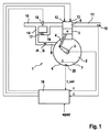
図1にはクランクケーシング2を有する内燃機関1の概略図が示されており、このクランクケーシングにはクランクシャフト3が配置されている。クランクシャフト3はコネクティングロッド4を介してピストン5に接続されており、このピストンはシリンダ6において往復運動するように配置されている。ここではわかりやすくするため、内燃機関の1つのシリンダだけが図示されているが、ふつう内燃機関は複数のシリンダ、例えば4つまたは6つのシリンダを有する。クランクケーシング2にはエンジンオイル7があり、このエンジンオイルは、ここに図示していない管路およびポンプを介して各潤滑個所に供給され、殊にシリンダ6におけるピストン5の摺動面にも供給される。エンジンオイルはオイルパン8に蓄えられている。ピストンケーシング2における超過圧力を下げるため、このケーシングは、エア抜き9によって内燃機関のインテークパイプ10に接続されている。公知のようにインテークパイプ10を介して周囲空気がシリンダ6に吸気され、燃焼排気ガスは、エグゾーストシステム11を介して再度周囲に放出される。各シリンダ6には、例えば電気的に制御されかつ高圧レールに接続された噴射バルブ12と、電気的な点火プラグ13とが割り当てられている。上記のエア抜きは、スロットルバルブ15の上流でインテークパイプ10に接続されているメイン供給管14と、断面積がより小さいサブ管路16とに分岐している。この断面積は、ここでは概略的に示した絞り17によって示されており、このサブ管路は、スロットルバルブ15の下流でインテークパイプ10に接続されている。
FIG. 1 shows a schematic view of an internal combustion engine 1 having a crank casing 2, in which a
制御装置18により、内燃機関の作動状態が制御される。制御装置18の入力側にはアクセルペダル角wpedと、クランクシャフト回転数nと、排気ガスシステムに配置されたラムダセンサ19によって測定したラムダ値λとが入力される。例えばスロットルバルブの位置、吸気圧力ないしは吸気温度などの別の入力量は、わかりやすくするためここでは図示していない。出力側には、例えば噴射バルブ12と、点火プラグ13と、スロットルバルブ15の位置とに対する制御信号が出力される。オイル温度T_OLは、オイル温度センサ20によって検出される。
The operating state of the internal combustion engine is controlled by the
オイル温度T_OLと、エンジンオイル内に実際にある燃料質量のモデルとから、エンジンオイル7からガスとして放出される燃料の質量流
![]()
![]()
図2は、本発明による方法の1実施例を流れ図で示しており、ステップ101では、ガスとして放出する燃料の体積流
![]()
![]()
![]()
![]()
![]()
![]()
![]()
![]()
![]()
![]()
![]()
![]()
上で説明した方法は、トルクリザーブを有する作動状態においても模倣することができる。このトルクリザーブにより、充填経路において目標充填量を増大させる。このためにスロットルバルブ15が開かれ、これによって内燃機関にはさらに多く空気が供給され、また噴射制御部ないしはラムダ制御部を介して多くの燃料も供給される。しかしながら点火経路ではこれによって目標点火角効率が低下することになる。それは、エンジン充填効率に基づいて最適なトルクが増大していたからである。したがってこの内燃機関は、高い燃料要求量および高い充填量で作動され、ここでクランクシャフトにおけるトルクは変わらないままである。
The method described above can also be imitated even in operating conditions with torque reserve. This torque reserve increases the target filling amount in the filling path. For this purpose, the
図3および図4には、本発明によるこのような方法の1実施例が示されている。図3には目標充填量rlsolおよび噴射時間teを求める方法の部分が示されており、図4にはトルクリザーブdmrを求める方法の部分が示されている。まず図3を検討する。上側のパスではブロックFEにおいて、予測した新鮮空気充填量rlpが求められる。この値には、混合気適合化の相対的な燃料割合のオフセットrkaが加算され、つぎにさらにこの値には混合気適合化制御のファクタfraならびにラムダ制御の制御ファクタfrが乗算される。図3の中央のパスでは、ガス放出の質量流mkausg_mから、すなわち機関における実際の体積流から、ならびに機関回転数nmotから、オイルからガスとして放出される相対的な燃料割合rkausg_mが求められる。この値は、上側のパスで求めた値から減算され、ここから燃料量rkが得られる。つぎにこの値から、燃料の化学量論的ファクタffuelを考慮するための補正ファクタならびに燃料圧に対する補正ファクタfpfuelを考慮して、噴射機関に対する値teを計算する。ただしこの値は、その下限が値TEMINに制限される。 3 and 4 show one embodiment of such a method according to the invention. FIG. 3 shows a method portion for obtaining the target filling amount rlsol and the injection time te, and FIG. 4 shows a portion for obtaining the torque reserve dmr. Consider first FIG. In the upper path, the predicted fresh air filling amount rlp is obtained in the block FE. This value is added to the relative fuel ratio offset rka of the mixture adaptation, and then this value is further multiplied by the mixture adaptation control factor fra and the lambda control control factor fr. In the central path of FIG. 3, the relative fuel fraction rkausg_m released from the oil as gas is determined from the mass flow mkausg_m of gas discharge, ie from the actual volume flow in the engine and from the engine speed nmot. This value is subtracted from the value obtained in the upper path, from which the fuel amount rk is obtained. Next, from this value, a value te for the injection engine is calculated in consideration of a correction factor for considering the fuel stoichiometric factor ffuel and a correction factor fpfuel for the fuel pressure. However, the lower limit of this value is limited to the value TEMIN.
図3の下側のパスにおいても、ドライバ所望トルクmifalと、トルクリザーブdmrと、既知の特性マップKFMIRLから得られるクランクシャフト回転数nmotとから充填目標値rlmdsが計算される。中央のパスにおいて求められるガス放出による相対的な燃料割合rkausgと、ガス放出の最大燃料割合fgausgmxとから、目標充填量に対する最小値rlmin_ausgが求められる。この値と、充填目標値rlmdsとから最大値を選択することにより、目標充填に対する最小値rlsolが計算され、この最小値がつぎにスロットルバルブの駆動制御に使用される。 Also in the lower path of FIG. 3, the charging target value rlmds is calculated from the driver desired torque mifal, the torque reserve dmr, and the crankshaft rotational speed nmot obtained from the known characteristic map KFMIRL. The minimum value rlmin_ausg with respect to the target filling amount is obtained from the relative fuel ratio rkausg due to gas discharge obtained in the central path and the maximum fuel ratio fgausgmx of gas discharge. By selecting the maximum value from this value and the filling target value rlmds, the minimum value rlsol for the target filling is calculated, and this minimum value is then used for drive control of the throttle valve.
図4には、ガス放出中のトルクリザーブの求め方が示されている。上側のパスでは、最小噴射時間TEMINと、これに加えて制御および混合気のファクタ等のfraなどの別の値と、混合気適合化の相対的な燃料割合のオフセットrkaと、別の値とから最小目標充填量の第1の値を求める。中央のパスでは、ガス放出による相対的な燃料割合rkausgが求められ、この値は上側のパスでも下側のパスでも使用される。この燃料割合、ガス放出質量流mkausgと、機関回転数nmotと、上記の質量流を充填度に換算するための定数KUMSRLとから求められる。最大値選択により、最小目標充填量rlsolmnが求められ、つぎにこの値は機関回転数nmotと共に特性マップKFMIOPを介してトルクに変換される。このトルクから上記のドライバ所望トルクmifalを減算する。この差分の下限は値0に制限され、また上記のトルクリザーブdmrを表す。 FIG. 4 shows how to obtain the torque reserve during gas discharge. In the upper pass, the minimum injection time TEMIN, plus another value such as fra, such as control and mixture factor, the offset rka of the relative fuel ratio for mixture adaptation, and another value To obtain the first value of the minimum target filling amount. In the middle pass, the relative fuel fraction rkausg due to outgassing is determined and this value is used in both the upper and lower passes. This fuel ratio, the gas discharge mass flow mkausg, the engine speed nmot, and the constant KUMSRL for converting the mass flow into the degree of filling are obtained. By selecting the maximum value, the minimum target filling amount rlsolmn is obtained, and this value is then converted into torque through the characteristic map KFMIOP together with the engine speed nmot. The driver desired torque mifal is subtracted from this torque. The lower limit of this difference is limited to a value of 0 and represents the torque reserve dmr described above.
図5には、本発明による方法の別の実施例がブロック図で示されている。ここではステップ201において惰走運転に移行する。ここではドライバ所望トルクは0に等しく、したがってドライバはアクセルペダルを離している。ドライブトレインは接続されており、機関回転数は下側の閾値よりも大きい。惰走運転において噴射はふつう遮断されており、したがって抑止されている。点火は引き続いて行われるため、シリンダにおける残留燃料も燃料する。トルクを低減するためにシリンダを停止する際には、高いガス放出が、クランクケーシングエア抜きを介する燃料による機関作動の継続に結び付いてはならない。これを回避するため、ガス放出が中くらいの場合および多い場合には噴射停止の禁止を起動する。このためにまずステップ202において、ガス放出率が中くらいまたは高い否かが求められる。このため、測定したガス放出率またはシミュレーションしたガス放出率と、最大閾値とを比較する。オプションYで示したこれを上回るガス放出率の場合、ガス放出率は中くらいから高く、またステップ203において、例えば、制御装置における特性ビットを介して噴射停止の禁止が設定される。オプションNで示したガス放出率が高くない場合にはステップ204において噴射停止が許可される。これも同様に相応する特性ビットによって実現することができる。ここでの境界条件は、惰走時に所要の制動トルクをさらに設定できなければならないことである。ここでは上記の噴射バルブを起動しなければならず、またこれを許容誤差について要求を維持するための最小許容噴時間TEMINよりも長い噴射時間で作動しなければならない。上記の可能な限りに遅い点火角を下回ってはならず、またラムダ値は、極端な場合、リッチ走行境界に達するまで低減することができる。
FIG. 5 shows a block diagram of another embodiment of the method according to the invention. Here, in
ガス放出が極端に多い場合、前に述べた条件は、閾値を下回る回転数時にもはや維持できない。それは、ガス放出によって燃料割合が高くなり過ぎるからである。このような極端なガス放出では、図5に示した方法を一部変更する。ここではいずれの場合にも上記の噴射停止が許可され、付加的には点火が遮断されてスロットルバルブが最大に開かれる。ガス放出が極端に多い場合には所定の燃料をインテークパイプに入れて、この燃料がもはや駆動トルクを形成することなしに燃焼し得ないようにする。したがって点火を遮断することにより、燃焼室において、制御されていない燃焼が回避され、上記のスロットルバルブを最大限に閉じることにより、触媒を損傷する新鮮空気質量流が付加的に回避される。 If the outgassing is extremely high, the previously mentioned conditions can no longer be maintained at revolutions below the threshold. This is because the fuel ratio becomes too high due to outgassing. In such extreme gas discharge, the method shown in FIG. 5 is partially changed. Here, in any case, the stop of the injection is permitted, and additionally, the ignition is cut off and the throttle valve is opened to the maximum. If the outgassing is extremely high, a predetermined fuel is put into the intake pipe so that this fuel can no longer burn without creating a driving torque. Therefore, by shutting off the ignition, uncontrolled combustion is avoided in the combustion chamber, and by closing the throttle valve to the maximum, fresh air mass flow that damages the catalyst is additionally avoided.
Claims (15)
前記のクランクケーシング(2)内のエンジンオイルから燃料がガスとして放出される際に、前記の内燃機関の動作点を変化させて、あらかじめ設定した空燃比を下回らないようにしたことを特徴とする、
内燃機関の作動方法。 In the operating method of the internal combustion engine, the crank casing (2) of the internal combustion engine has an air vent (9) reaching the intake pipe (10) of the internal combustion engine.
When fuel is released as gas from engine oil in the crank casing (2), the operating point of the internal combustion engine is changed so as not to fall below a preset air-fuel ratio. ,
An internal combustion engine operating method.
請求項1に記載の方法。 Changing the operating point of the internal combustion engine to increase fuel consumption;
The method of claim 1.
請求項2に記載の方法。 Reducing the ignition efficiency to increase the fuel consumption,
The method of claim 2.
請求項2または3に記載の方法。 Increase the idling target speed,
The method according to claim 2 or 3.
請求項1から4までのいずれか1項に記載の方法。 By reducing the target injection amount (rk), a lambda value (lambda) of about 1 is obtained from the sum of the target injection amount (rk) and the additionally supplied gas release fuel amount (rkausg). To be able to
The method according to any one of claims 1 to 4.
請求項1から5までのいずれか1項に記載の方法。 The preset minimum air-fuel ratio represents a rich travel boundary,
6. A method according to any one of claims 1-5.
請求項1から6までのいずれか1項に記載の方法。 The preset minimum air / fuel ratio is stoichiometric air / fuel ratio lambda = 1.
7. A method according to any one of claims 1-6.
請求項7に記載の方法。 Set the lower limit of the above injection amount so that it does not fall below the minimum injection time (TEMIN),
The method of claim 7.
請求項1から8までのいずれか1項に記載の方法。 To increase the fuel consumption, increase the target fill (rlsol) and decrease the ignition angle efficiency;
9. A method according to any one of claims 1-8.
請求項8に記載の方法。 Increasing the target fill (rlsol) by increasing the torque reserve (dmr);
The method of claim 8.
請求項9または10に記載の方法。 Increasing the target air amount by opening the throttle valve (15),
The method according to claim 9 or 10.
請求項1から11までのいずれか1項に記載の方法。 In order to increase the target filling amount, the minimum torque reserve (dmr) is determined on the basis of the minimum injection time (TEMIN) and on the basis of the current gas discharge mass flow (mkausg).
12. A method according to any one of claims 1 to 11.
請求項1から12までのいずれか1項に記載の方法。 Do not stop injection when releasing gas,
13. A method according to any one of claims 1-12.
請求項1から13までのいずれか1項に記載の方法。 Shuts off ignition when outgassing in inertial operation,
14. A method according to any one of claims 1 to 13.
請求項14に記載の方法。 Close the throttle valve (15) to the maximum,
The method according to claim 14.
Applications Claiming Priority (3)
| Application Number | Priority Date | Filing Date | Title |
|---|---|---|---|
| DE102008042638.5 | 2008-10-07 | ||
| DE102008042638A DE102008042638A1 (en) | 2008-10-07 | 2008-10-07 | Method for operating an internal combustion engine |
| PCT/EP2009/061187 WO2010040600A2 (en) | 2008-10-07 | 2009-08-31 | Method for operating an internal combustion engine |
Publications (1)
| Publication Number | Publication Date |
|---|---|
| JP2012504730A true JP2012504730A (en) | 2012-02-23 |
Family
ID=41258294
Family Applications (1)
| Application Number | Title | Priority Date | Filing Date |
|---|---|---|---|
| JP2011530435A Pending JP2012504730A (en) | 2008-10-07 | 2009-08-31 | Method of operating an internal combustion engine |
Country Status (6)
| Country | Link |
|---|---|
| US (1) | US8505518B2 (en) |
| JP (1) | JP2012504730A (en) |
| CN (1) | CN102171430B (en) |
| BR (1) | BRPI0920919B1 (en) |
| DE (1) | DE102008042638A1 (en) |
| WO (1) | WO2010040600A2 (en) |
Families Citing this family (11)
| Publication number | Priority date | Publication date | Assignee | Title |
|---|---|---|---|---|
| DE102010043780B4 (en) * | 2010-11-11 | 2013-07-18 | Continental Automotive Gmbh | Determining a fuel outgassing from a lubricant within an internal combustion engine and lambda adaptation based on the determined fuel outgassing |
| JP5158228B2 (en) * | 2011-04-28 | 2013-03-06 | トヨタ自動車株式会社 | Internal combustion engine control device |
| US20140096754A1 (en) * | 2012-10-08 | 2014-04-10 | Serge V. Monros | Pcv valve and pollution control system |
| JP2015031213A (en) * | 2013-08-02 | 2015-02-16 | 株式会社日本自動車部品総合研究所 | Internal combustion engine |
| DE102014220400B4 (en) * | 2014-10-08 | 2016-09-22 | Continental Automotive Gmbh | Method and control device for determining a torque reserve |
| US9759168B2 (en) | 2015-05-07 | 2017-09-12 | Ford Global Technologies, Llc | Increasing crankcase ventilation flow rate via active flow control |
| EP3165748A1 (en) * | 2015-11-04 | 2017-05-10 | GE Jenbacher GmbH & Co. OG | Internal combustion engine with injection amount control |
| SE542518C2 (en) * | 2016-06-22 | 2020-06-02 | Scania Cv Ab | Method and system for controlling an internal combustion engine experiencing uncontrolled behavour in a vehicle |
| DE102017102367B4 (en) | 2017-02-07 | 2023-10-12 | Volkswagen Aktiengesellschaft | Method for increasing the tank ventilation flush quantity by completely suppressing the injection of at least one cylinder |
| CN107476892B (en) * | 2017-07-28 | 2020-02-14 | 宝沃汽车(中国)有限公司 | Engine control method and system and vehicle |
| CN111946526B (en) * | 2020-07-24 | 2021-07-06 | 东风汽车集团有限公司 | Exhaust temperature protection method based on air-fuel ratio and time delay response |
Citations (9)
| Publication number | Priority date | Publication date | Assignee | Title |
|---|---|---|---|---|
| JPH04234543A (en) * | 1990-12-28 | 1992-08-24 | Honda Motor Co Ltd | Engine speed controller of internal combustion engine |
| JPH04308336A (en) * | 1991-04-02 | 1992-10-30 | Honda Motor Co Ltd | Air-fuel ratio controller |
| JP2005042575A (en) * | 2003-07-24 | 2005-02-17 | Toyota Motor Corp | Control device of internal combustion engine |
| JP2006009597A (en) * | 2004-06-22 | 2006-01-12 | Toyota Motor Corp | Fuel dilution estimating device for engine oil |
| JP2006144584A (en) * | 2004-11-17 | 2006-06-08 | Denso Corp | Fuel injection control system for internal combustion engine |
| JP2006177288A (en) * | 2004-12-24 | 2006-07-06 | Denso Corp | Fuel system abnormality detection device for engine |
| JP2007127076A (en) * | 2005-11-04 | 2007-05-24 | Toyota Motor Corp | Abnormality diagnosis device for cylinder injection type internal combustion engine |
| JP2007192113A (en) * | 2006-01-19 | 2007-08-02 | Toyota Motor Corp | Vehicle, and control method thereof |
| JP2008202554A (en) * | 2007-02-22 | 2008-09-04 | Toyota Motor Corp | Control device for internal combustion engine |
Family Cites Families (19)
| Publication number | Priority date | Publication date | Assignee | Title |
|---|---|---|---|---|
| US3662724A (en) * | 1971-01-13 | 1972-05-16 | Chrysler Corp | Crankcase ventilation |
| US4570603A (en) * | 1983-09-01 | 1986-02-18 | Roberto Piedrafita | Apparatus for improving gasoline consumption, power and reducing emission pollutants of internal combustion engines |
| JPH07305670A (en) * | 1994-05-11 | 1995-11-21 | Sanshin Ind Co Ltd | Two cycle engine |
| US5438967A (en) | 1992-10-21 | 1995-08-08 | Toyota Jidosha Kabushiki Kaisha | Internal combustion device |
| DE4423003C2 (en) * | 1993-07-06 | 1999-01-21 | Ford Werke Ag | Method and device for reducing NO¶x¶ in exhaust gases from automotive internal combustion engines |
| DE4423241C2 (en) * | 1994-07-02 | 2003-04-10 | Bosch Gmbh Robert | Method for adjusting the composition of the operating mixture for an internal combustion engine |
| DE19527628A1 (en) | 1995-07-28 | 1997-01-30 | Bosch Gmbh Robert | Two=stroke IC engine - has lifting piston forming part of lifting=piston air compressor integrated into crankcase or combustion cylinder |
| JP4308336B2 (en) | 1997-03-14 | 2009-08-05 | 株式会社日本吸収体技術研究所 | Microfibrillar fine fiber structure and method for producing the same |
| JPH1136922A (en) * | 1997-07-25 | 1999-02-09 | Hitachi Ltd | Controller of cylinder injection type internal combustion engine |
| DE19910503C1 (en) * | 1999-03-10 | 2000-07-06 | Daimler Chrysler Ag | Desulfating the nitrogen oxide or sulfur oxide storage unit of a catalytic converter comprises variably operating different groups of engine cylinders with different fuel/air ratios |
| JP4234543B2 (en) | 2003-09-09 | 2009-03-04 | 富士通マイクロエレクトロニクス株式会社 | AD converter |
| DE102004008891A1 (en) * | 2004-02-24 | 2005-09-08 | Robert Bosch Gmbh | Method for operating an internal combustion engine |
| WO2006102510A2 (en) * | 2005-03-24 | 2006-09-28 | Cooper-Standard Automotive, Inc. | Positive crankcase ventilation valve assembly with a vacuum pulsation dampener |
| EP1944490A1 (en) * | 2007-01-10 | 2008-07-16 | GM Global Technology Operations, Inc. | Fuel control method |
| JP4321606B2 (en) * | 2007-02-28 | 2009-08-26 | トヨタ自動車株式会社 | Blow-by gas reduction device, cylinder head used in the blow-by gas reduction device, and internal combustion engine including the blow-by gas reduction device |
| JP2008267273A (en) * | 2007-04-20 | 2008-11-06 | Aisan Ind Co Ltd | Blow-by gas returning device |
| DE102007042406B4 (en) * | 2007-09-06 | 2023-07-27 | Robert Bosch Gmbh | Method for considering the outgassing of fuel from the engine oil of an internal combustion engine |
| US7677228B2 (en) * | 2007-11-16 | 2010-03-16 | Manookian Jr Arman | Crankcase vapor purification device |
| US8353276B2 (en) * | 2008-07-18 | 2013-01-15 | Ford Global Technologies, Llc | System and method for storing crankcase gases to improve engine air-fuel control |
-
2008
- 2008-10-07 DE DE102008042638A patent/DE102008042638A1/en active Pending
-
2009
- 2009-08-31 WO PCT/EP2009/061187 patent/WO2010040600A2/en active Application Filing
- 2009-08-31 BR BRPI0920919 patent/BRPI0920919B1/en active IP Right Grant
- 2009-08-31 US US12/998,306 patent/US8505518B2/en active Active
- 2009-08-31 CN CN200980139490.0A patent/CN102171430B/en active Active
- 2009-08-31 JP JP2011530435A patent/JP2012504730A/en active Pending
Patent Citations (9)
| Publication number | Priority date | Publication date | Assignee | Title |
|---|---|---|---|---|
| JPH04234543A (en) * | 1990-12-28 | 1992-08-24 | Honda Motor Co Ltd | Engine speed controller of internal combustion engine |
| JPH04308336A (en) * | 1991-04-02 | 1992-10-30 | Honda Motor Co Ltd | Air-fuel ratio controller |
| JP2005042575A (en) * | 2003-07-24 | 2005-02-17 | Toyota Motor Corp | Control device of internal combustion engine |
| JP2006009597A (en) * | 2004-06-22 | 2006-01-12 | Toyota Motor Corp | Fuel dilution estimating device for engine oil |
| JP2006144584A (en) * | 2004-11-17 | 2006-06-08 | Denso Corp | Fuel injection control system for internal combustion engine |
| JP2006177288A (en) * | 2004-12-24 | 2006-07-06 | Denso Corp | Fuel system abnormality detection device for engine |
| JP2007127076A (en) * | 2005-11-04 | 2007-05-24 | Toyota Motor Corp | Abnormality diagnosis device for cylinder injection type internal combustion engine |
| JP2007192113A (en) * | 2006-01-19 | 2007-08-02 | Toyota Motor Corp | Vehicle, and control method thereof |
| JP2008202554A (en) * | 2007-02-22 | 2008-09-04 | Toyota Motor Corp | Control device for internal combustion engine |
Also Published As
| Publication number | Publication date |
|---|---|
| CN102171430A (en) | 2011-08-31 |
| BRPI0920919A2 (en) | 2015-12-29 |
| US8505518B2 (en) | 2013-08-13 |
| WO2010040600A2 (en) | 2010-04-15 |
| DE102008042638A1 (en) | 2010-04-08 |
| WO2010040600A3 (en) | 2010-07-08 |
| CN102171430B (en) | 2014-08-13 |
| BRPI0920919B1 (en) | 2019-12-10 |
| US20110253079A1 (en) | 2011-10-20 |
Similar Documents
| Publication | Publication Date | Title |
|---|---|---|
| JP2012504730A (en) | Method of operating an internal combustion engine | |
| US10267257B2 (en) | Method and system for engine starting control | |
| US8275538B2 (en) | Multi-fuel engine starting control system and method | |
| US10760520B2 (en) | Method for fuel injection control | |
| US8413643B2 (en) | Multi-fuel engine control system and method | |
| US9260991B2 (en) | System and method for storing crankcase gases to improve engine air-fuel control | |
| US8352163B2 (en) | Method for controlling an engine | |
| US8165780B2 (en) | Boosted engine control responsive to driver selected performance | |
| US8099949B2 (en) | Engine exhaust temperature regulation | |
| US8567370B2 (en) | Method and system for engine control | |
| RU2666709C2 (en) | Method for turbo-charged engine (options) | |
| US20140297162A1 (en) | Method and system for engine control | |
| US20100312459A1 (en) | Internal combustion engine controller | |
| CN105736166B (en) | Zero flow lubrication for high pressure fuel pump | |
| US9316172B2 (en) | Reducing enrichment due to minimum pulse width constraint | |
| US20180363572A1 (en) | System and method for reducing variable compression ratio engine shutdown shake | |
| CN112459912A (en) | Method and system for improving efficiency of exhaust system | |
| RU2709036C2 (en) | Method (embodiments) and fuel supply system to engine | |
| US10337485B2 (en) | Systems and methods for reducing engine torque through spark retard |
Legal Events
| Date | Code | Title | Description |
|---|---|---|---|
| A977 | Report on retrieval |
Free format text: JAPANESE INTERMEDIATE CODE: A971007 Effective date: 20120626 |
|
| A131 | Notification of reasons for refusal |
Free format text: JAPANESE INTERMEDIATE CODE: A131 Effective date: 20120628 |
|
| A601 | Written request for extension of time |
Free format text: JAPANESE INTERMEDIATE CODE: A601 Effective date: 20120925 |
|
| A602 | Written permission of extension of time |
Free format text: JAPANESE INTERMEDIATE CODE: A602 Effective date: 20121002 |
|
| A521 | Request for written amendment filed |
Free format text: JAPANESE INTERMEDIATE CODE: A523 Effective date: 20121226 |
|
| A131 | Notification of reasons for refusal |
Free format text: JAPANESE INTERMEDIATE CODE: A131 Effective date: 20130319 |
|
| A601 | Written request for extension of time |
Free format text: JAPANESE INTERMEDIATE CODE: A601 Effective date: 20130619 |
|
| A602 | Written permission of extension of time |
Free format text: JAPANESE INTERMEDIATE CODE: A602 Effective date: 20130626 |
|
| A521 | Request for written amendment filed |
Free format text: JAPANESE INTERMEDIATE CODE: A523 Effective date: 20130919 |
|
| A02 | Decision of refusal |
Free format text: JAPANESE INTERMEDIATE CODE: A02 Effective date: 20131028 |