JP2012504044A - Gas-liquid contactor and gas-liquid contact method - Google Patents
Gas-liquid contactor and gas-liquid contact method Download PDFInfo
- Publication number
- JP2012504044A JP2012504044A JP2011529330A JP2011529330A JP2012504044A JP 2012504044 A JP2012504044 A JP 2012504044A JP 2011529330 A JP2011529330 A JP 2011529330A JP 2011529330 A JP2011529330 A JP 2011529330A JP 2012504044 A JP2012504044 A JP 2012504044A
- Authority
- JP
- Japan
- Prior art keywords
- nozzle
- gas
- liquid
- liquid jets
- range
- Prior art date
- Legal status (The legal status is an assumption and is not a legal conclusion. Google has not performed a legal analysis and makes no representation as to the accuracy of the status listed.)
- Withdrawn
Links
- 239000007788 liquid Substances 0.000 title claims abstract description 214
- 238000000034 method Methods 0.000 title claims abstract description 92
- 230000003993 interaction Effects 0.000 claims abstract description 17
- 239000007789 gas Substances 0.000 claims description 126
- 239000012530 fluid Substances 0.000 claims description 44
- 238000012546 transfer Methods 0.000 claims description 35
- 238000006243 chemical reaction Methods 0.000 claims description 15
- MWUXSHHQAYIFBG-UHFFFAOYSA-N nitrogen oxide Inorganic materials O=[N] MWUXSHHQAYIFBG-UHFFFAOYSA-N 0.000 claims description 15
- QGZKDVFQNNGYKY-UHFFFAOYSA-N Ammonia Chemical compound N QGZKDVFQNNGYKY-UHFFFAOYSA-N 0.000 claims description 12
- CURLTUGMZLYLDI-UHFFFAOYSA-N Carbon dioxide Chemical compound O=C=O CURLTUGMZLYLDI-UHFFFAOYSA-N 0.000 claims description 12
- 239000002002 slurry Substances 0.000 claims description 9
- XLYOFNOQVPJJNP-UHFFFAOYSA-N water Substances O XLYOFNOQVPJJNP-UHFFFAOYSA-N 0.000 claims description 9
- 150000001412 amines Chemical class 0.000 claims description 8
- QVGXLLKOCUKJST-UHFFFAOYSA-N atomic oxygen Chemical compound [O] QVGXLLKOCUKJST-UHFFFAOYSA-N 0.000 claims description 8
- 239000001301 oxygen Substances 0.000 claims description 8
- 229910052760 oxygen Inorganic materials 0.000 claims description 8
- 239000000463 material Substances 0.000 claims description 7
- 229910021529 ammonia Inorganic materials 0.000 claims description 6
- 239000001569 carbon dioxide Substances 0.000 claims description 6
- 229910002092 carbon dioxide Inorganic materials 0.000 claims description 6
- 239000000460 chlorine Substances 0.000 claims description 6
- 239000012266 salt solution Substances 0.000 claims description 6
- 239000007787 solid Substances 0.000 claims description 5
- XTQHKBHJIVJGKJ-UHFFFAOYSA-N sulfur monoxide Chemical class S=O XTQHKBHJIVJGKJ-UHFFFAOYSA-N 0.000 claims description 5
- PXHVJJICTQNCMI-UHFFFAOYSA-N Nickel Chemical compound [Ni] PXHVJJICTQNCMI-UHFFFAOYSA-N 0.000 claims description 4
- 229910052815 sulfur oxide Inorganic materials 0.000 claims description 4
- ZAMOUSCENKQFHK-UHFFFAOYSA-N Chlorine atom Chemical compound [Cl] ZAMOUSCENKQFHK-UHFFFAOYSA-N 0.000 claims description 3
- 230000002378 acidificating effect Effects 0.000 claims description 3
- 150000001447 alkali salts Chemical class 0.000 claims description 3
- 229910052782 aluminium Inorganic materials 0.000 claims description 3
- XAGFODPZIPBFFR-UHFFFAOYSA-N aluminium Chemical compound [Al] XAGFODPZIPBFFR-UHFFFAOYSA-N 0.000 claims description 3
- 150000003863 ammonium salts Chemical class 0.000 claims description 3
- 239000012267 brine Substances 0.000 claims description 3
- 159000000007 calcium salts Chemical class 0.000 claims description 3
- 229910052801 chlorine Inorganic materials 0.000 claims description 3
- 229910052736 halogen Inorganic materials 0.000 claims description 3
- 150000002367 halogens Chemical class 0.000 claims description 3
- WQYVRQLZKVEZGA-UHFFFAOYSA-N hypochlorite Chemical class Cl[O-] WQYVRQLZKVEZGA-UHFFFAOYSA-N 0.000 claims description 3
- 159000000003 magnesium salts Chemical class 0.000 claims description 3
- 150000002978 peroxides Chemical class 0.000 claims description 3
- 150000003839 salts Chemical class 0.000 claims description 3
- HPALAKNZSZLMCH-UHFFFAOYSA-M sodium;chloride;hydrate Chemical compound O.[Na+].[Cl-] HPALAKNZSZLMCH-UHFFFAOYSA-M 0.000 claims description 3
- VYZAMTAEIAYCRO-UHFFFAOYSA-N Chromium Chemical compound [Cr] VYZAMTAEIAYCRO-UHFFFAOYSA-N 0.000 claims description 2
- RYGMFSIKBFXOCR-UHFFFAOYSA-N Copper Chemical compound [Cu] RYGMFSIKBFXOCR-UHFFFAOYSA-N 0.000 claims description 2
- 239000004642 Polyimide Substances 0.000 claims description 2
- 229910000831 Steel Inorganic materials 0.000 claims description 2
- 239000011651 chromium Substances 0.000 claims description 2
- 229910052804 chromium Inorganic materials 0.000 claims description 2
- 239000011248 coating agent Substances 0.000 claims description 2
- 238000000576 coating method Methods 0.000 claims description 2
- 239000002131 composite material Substances 0.000 claims description 2
- 229910052802 copper Inorganic materials 0.000 claims description 2
- 239000010949 copper Substances 0.000 claims description 2
- 229910052751 metal Inorganic materials 0.000 claims description 2
- 239000002184 metal Substances 0.000 claims description 2
- 229910052759 nickel Inorganic materials 0.000 claims description 2
- 229920001721 polyimide Polymers 0.000 claims description 2
- 229920000642 polymer Polymers 0.000 claims description 2
- 239000010959 steel Substances 0.000 claims description 2
- 239000002245 particle Substances 0.000 claims 3
- 239000013535 sea water Substances 0.000 claims 2
- TXKMVPPZCYKFAC-UHFFFAOYSA-N disulfur monoxide Inorganic materials O=S=S TXKMVPPZCYKFAC-UHFFFAOYSA-N 0.000 claims 1
- 238000004140 cleaning Methods 0.000 abstract description 19
- 238000004891 communication Methods 0.000 abstract description 5
- 239000012071 phase Substances 0.000 description 35
- 229910001220 stainless steel Inorganic materials 0.000 description 11
- 239000010935 stainless steel Substances 0.000 description 11
- 239000002351 wastewater Substances 0.000 description 11
- LYCAIKOWRPUZTN-UHFFFAOYSA-N Ethylene glycol Chemical compound OCCO LYCAIKOWRPUZTN-UHFFFAOYSA-N 0.000 description 9
- 238000012545 processing Methods 0.000 description 9
- MHAJPDPJQMAIIY-UHFFFAOYSA-N Hydrogen peroxide Chemical compound OO MHAJPDPJQMAIIY-UHFFFAOYSA-N 0.000 description 8
- 230000008901 benefit Effects 0.000 description 8
- 239000007791 liquid phase Substances 0.000 description 7
- 230000007423 decrease Effects 0.000 description 5
- 238000010586 diagram Methods 0.000 description 5
- 238000012360 testing method Methods 0.000 description 5
- 238000004148 unit process Methods 0.000 description 5
- MYMOFIZGZYHOMD-UHFFFAOYSA-N Dioxygen Chemical compound O=O MYMOFIZGZYHOMD-UHFFFAOYSA-N 0.000 description 4
- 238000010521 absorption reaction Methods 0.000 description 4
- 239000003153 chemical reaction reagent Substances 0.000 description 4
- 230000005484 gravity Effects 0.000 description 4
- 230000008569 process Effects 0.000 description 4
- 238000007789 sealing Methods 0.000 description 4
- 239000000126 substance Substances 0.000 description 4
- IJGRMHOSHXDMSA-UHFFFAOYSA-N Atomic nitrogen Chemical compound N#N IJGRMHOSHXDMSA-UHFFFAOYSA-N 0.000 description 3
- 238000005520 cutting process Methods 0.000 description 3
- 239000006185 dispersion Substances 0.000 description 3
- 239000000446 fuel Substances 0.000 description 3
- 230000007246 mechanism Effects 0.000 description 3
- 238000000926 separation method Methods 0.000 description 3
- 239000000243 solution Substances 0.000 description 3
- 230000000087 stabilizing effect Effects 0.000 description 3
- 238000003466 welding Methods 0.000 description 3
- 238000010564 aerobic fermentation Methods 0.000 description 2
- 239000007864 aqueous solution Substances 0.000 description 2
- 238000000889 atomisation Methods 0.000 description 2
- 238000001311 chemical methods and process Methods 0.000 description 2
- 239000000356 contaminant Substances 0.000 description 2
- 230000003247 decreasing effect Effects 0.000 description 2
- 238000009826 distribution Methods 0.000 description 2
- 230000000694 effects Effects 0.000 description 2
- 238000009760 electrical discharge machining Methods 0.000 description 2
- 238000002474 experimental method Methods 0.000 description 2
- 238000012986 modification Methods 0.000 description 2
- 230000004048 modification Effects 0.000 description 2
- 239000001993 wax Substances 0.000 description 2
- KZBUYRJDOAKODT-UHFFFAOYSA-N Chlorine Chemical compound ClCl KZBUYRJDOAKODT-UHFFFAOYSA-N 0.000 description 1
- PRXLCSIMRQFQMX-UHFFFAOYSA-N [O].[I] Chemical compound [O].[I] PRXLCSIMRQFQMX-UHFFFAOYSA-N 0.000 description 1
- NIXOWILDQLNWCW-UHFFFAOYSA-N acrylic acid group Chemical group C(C=C)(=O)O NIXOWILDQLNWCW-UHFFFAOYSA-N 0.000 description 1
- 239000003463 adsorbent Substances 0.000 description 1
- 239000000443 aerosol Substances 0.000 description 1
- 238000013019 agitation Methods 0.000 description 1
- 150000008044 alkali metal hydroxides Chemical class 0.000 description 1
- 230000031018 biological processes and functions Effects 0.000 description 1
- 239000003245 coal Substances 0.000 description 1
- 238000004581 coalescence Methods 0.000 description 1
- 238000002485 combustion reaction Methods 0.000 description 1
- 150000001875 compounds Chemical class 0.000 description 1
- 230000007812 deficiency Effects 0.000 description 1
- 238000013461 design Methods 0.000 description 1
- 238000009792 diffusion process Methods 0.000 description 1
- 229910001873 dinitrogen Inorganic materials 0.000 description 1
- 238000004821 distillation Methods 0.000 description 1
- 230000004151 fermentation Effects 0.000 description 1
- 238000011049 filling Methods 0.000 description 1
- -1 for example Substances 0.000 description 1
- 230000006872 improvement Effects 0.000 description 1
- 239000011261 inert gas Substances 0.000 description 1
- 230000001788 irregular Effects 0.000 description 1
- 238000003754 machining Methods 0.000 description 1
- 238000002844 melting Methods 0.000 description 1
- 230000008018 melting Effects 0.000 description 1
- 244000005700 microbiome Species 0.000 description 1
- 239000000203 mixture Substances 0.000 description 1
- 229910052757 nitrogen Inorganic materials 0.000 description 1
- 239000012188 paraffin wax Substances 0.000 description 1
- 239000000376 reactant Substances 0.000 description 1
- 230000035945 sensitivity Effects 0.000 description 1
- 239000010865 sewage Substances 0.000 description 1
- 238000001179 sorption measurement Methods 0.000 description 1
- 238000010561 standard procedure Methods 0.000 description 1
- 239000008399 tap water Substances 0.000 description 1
- 235000020679 tap water Nutrition 0.000 description 1
- 239000010409 thin film Substances 0.000 description 1
- WFKWXMTUELFFGS-UHFFFAOYSA-N tungsten Chemical compound [W] WFKWXMTUELFFGS-UHFFFAOYSA-N 0.000 description 1
- 229910052721 tungsten Inorganic materials 0.000 description 1
- 239000010937 tungsten Substances 0.000 description 1
- 238000011144 upstream manufacturing Methods 0.000 description 1
- 238000009763 wire-cut EDM Methods 0.000 description 1
Images


Classifications
-
- B—PERFORMING OPERATIONS; TRANSPORTING
- B01—PHYSICAL OR CHEMICAL PROCESSES OR APPARATUS IN GENERAL
- B01J—CHEMICAL OR PHYSICAL PROCESSES, e.g. CATALYSIS OR COLLOID CHEMISTRY; THEIR RELEVANT APPARATUS
- B01J10/00—Chemical processes in general for reacting liquid with gaseous media other than in the presence of solid particles, or apparatus specially adapted therefor
-
- B—PERFORMING OPERATIONS; TRANSPORTING
- B01—PHYSICAL OR CHEMICAL PROCESSES OR APPARATUS IN GENERAL
- B01D—SEPARATION
- B01D53/00—Separation of gases or vapours; Recovering vapours of volatile solvents from gases; Chemical or biological purification of waste gases, e.g. engine exhaust gases, smoke, fumes, flue gases, aerosols
- B01D53/14—Separation of gases or vapours; Recovering vapours of volatile solvents from gases; Chemical or biological purification of waste gases, e.g. engine exhaust gases, smoke, fumes, flue gases, aerosols by absorption
- B01D53/1456—Removing acid components
- B01D53/1462—Removing mixtures of hydrogen sulfide and carbon dioxide
-
- B—PERFORMING OPERATIONS; TRANSPORTING
- B01—PHYSICAL OR CHEMICAL PROCESSES OR APPARATUS IN GENERAL
- B01D—SEPARATION
- B01D53/00—Separation of gases or vapours; Recovering vapours of volatile solvents from gases; Chemical or biological purification of waste gases, e.g. engine exhaust gases, smoke, fumes, flue gases, aerosols
- B01D53/14—Separation of gases or vapours; Recovering vapours of volatile solvents from gases; Chemical or biological purification of waste gases, e.g. engine exhaust gases, smoke, fumes, flue gases, aerosols by absorption
- B01D53/1456—Removing acid components
- B01D53/1468—Removing hydrogen sulfide
-
- B—PERFORMING OPERATIONS; TRANSPORTING
- B01—PHYSICAL OR CHEMICAL PROCESSES OR APPARATUS IN GENERAL
- B01D—SEPARATION
- B01D53/00—Separation of gases or vapours; Recovering vapours of volatile solvents from gases; Chemical or biological purification of waste gases, e.g. engine exhaust gases, smoke, fumes, flue gases, aerosols
- B01D53/14—Separation of gases or vapours; Recovering vapours of volatile solvents from gases; Chemical or biological purification of waste gases, e.g. engine exhaust gases, smoke, fumes, flue gases, aerosols by absorption
- B01D53/1456—Removing acid components
- B01D53/1475—Removing carbon dioxide
-
- B—PERFORMING OPERATIONS; TRANSPORTING
- B01—PHYSICAL OR CHEMICAL PROCESSES OR APPARATUS IN GENERAL
- B01D—SEPARATION
- B01D53/00—Separation of gases or vapours; Recovering vapours of volatile solvents from gases; Chemical or biological purification of waste gases, e.g. engine exhaust gases, smoke, fumes, flue gases, aerosols
- B01D53/14—Separation of gases or vapours; Recovering vapours of volatile solvents from gases; Chemical or biological purification of waste gases, e.g. engine exhaust gases, smoke, fumes, flue gases, aerosols by absorption
- B01D53/1493—Selection of liquid materials for use as absorbents
-
- B—PERFORMING OPERATIONS; TRANSPORTING
- B01—PHYSICAL OR CHEMICAL PROCESSES OR APPARATUS IN GENERAL
- B01D—SEPARATION
- B01D53/00—Separation of gases or vapours; Recovering vapours of volatile solvents from gases; Chemical or biological purification of waste gases, e.g. engine exhaust gases, smoke, fumes, flue gases, aerosols
- B01D53/14—Separation of gases or vapours; Recovering vapours of volatile solvents from gases; Chemical or biological purification of waste gases, e.g. engine exhaust gases, smoke, fumes, flue gases, aerosols by absorption
- B01D53/18—Absorbing units; Liquid distributors therefor
-
- B—PERFORMING OPERATIONS; TRANSPORTING
- B01—PHYSICAL OR CHEMICAL PROCESSES OR APPARATUS IN GENERAL
- B01D—SEPARATION
- B01D53/00—Separation of gases or vapours; Recovering vapours of volatile solvents from gases; Chemical or biological purification of waste gases, e.g. engine exhaust gases, smoke, fumes, flue gases, aerosols
- B01D53/34—Chemical or biological purification of waste gases
- B01D53/46—Removing components of defined structure
- B01D53/62—Carbon oxides
-
- B—PERFORMING OPERATIONS; TRANSPORTING
- B01—PHYSICAL OR CHEMICAL PROCESSES OR APPARATUS IN GENERAL
- B01D—SEPARATION
- B01D53/00—Separation of gases or vapours; Recovering vapours of volatile solvents from gases; Chemical or biological purification of waste gases, e.g. engine exhaust gases, smoke, fumes, flue gases, aerosols
- B01D53/34—Chemical or biological purification of waste gases
- B01D53/74—General processes for purification of waste gases; Apparatus or devices specially adapted therefor
- B01D53/77—Liquid phase processes
- B01D53/78—Liquid phase processes with gas-liquid contact
-
- B—PERFORMING OPERATIONS; TRANSPORTING
- B01—PHYSICAL OR CHEMICAL PROCESSES OR APPARATUS IN GENERAL
- B01F—MIXING, e.g. DISSOLVING, EMULSIFYING OR DISPERSING
- B01F25/00—Flow mixers; Mixers for falling materials, e.g. solid particles
- B01F25/30—Injector mixers
-
- C—CHEMISTRY; METALLURGY
- C10—PETROLEUM, GAS OR COKE INDUSTRIES; TECHNICAL GASES CONTAINING CARBON MONOXIDE; FUELS; LUBRICANTS; PEAT
- C10L—FUELS NOT OTHERWISE PROVIDED FOR; NATURAL GAS; SYNTHETIC NATURAL GAS OBTAINED BY PROCESSES NOT COVERED BY SUBCLASSES C10G, C10K; LIQUEFIED PETROLEUM GAS; ADDING MATERIALS TO FUELS OR FIRES TO REDUCE SMOKE OR UNDESIRABLE DEPOSITS OR TO FACILITATE SOOT REMOVAL; FIRELIGHTERS
- C10L3/00—Gaseous fuels; Natural gas; Synthetic natural gas obtained by processes not covered by subclass C10G, C10K; Liquefied petroleum gas
- C10L3/06—Natural gas; Synthetic natural gas obtained by processes not covered by C10G, C10K3/02 or C10K3/04
- C10L3/10—Working-up natural gas or synthetic natural gas
- C10L3/101—Removal of contaminants
- C10L3/102—Removal of contaminants of acid contaminants
-
- H—ELECTRICITY
- H01—ELECTRIC ELEMENTS
- H01S—DEVICES USING THE PROCESS OF LIGHT AMPLIFICATION BY STIMULATED EMISSION OF RADIATION [LASER] TO AMPLIFY OR GENERATE LIGHT; DEVICES USING STIMULATED EMISSION OF ELECTROMAGNETIC RADIATION IN WAVE RANGES OTHER THAN OPTICAL
- H01S3/00—Lasers, i.e. devices using stimulated emission of electromagnetic radiation in the infrared, visible or ultraviolet wave range
- H01S3/09—Processes or apparatus for excitation, e.g. pumping
- H01S3/095—Processes or apparatus for excitation, e.g. pumping using chemical or thermal pumping
-
- B—PERFORMING OPERATIONS; TRANSPORTING
- B01—PHYSICAL OR CHEMICAL PROCESSES OR APPARATUS IN GENERAL
- B01D—SEPARATION
- B01D2251/00—Reactants
- B01D2251/10—Oxidants
- B01D2251/106—Peroxides
-
- B—PERFORMING OPERATIONS; TRANSPORTING
- B01—PHYSICAL OR CHEMICAL PROCESSES OR APPARATUS IN GENERAL
- B01D—SEPARATION
- B01D2251/00—Reactants
- B01D2251/20—Reductants
- B01D2251/206—Ammonium compounds
- B01D2251/2065—Ammonium hydroxide
-
- B—PERFORMING OPERATIONS; TRANSPORTING
- B01—PHYSICAL OR CHEMICAL PROCESSES OR APPARATUS IN GENERAL
- B01D—SEPARATION
- B01D2251/00—Reactants
- B01D2251/30—Alkali metal compounds
-
- B—PERFORMING OPERATIONS; TRANSPORTING
- B01—PHYSICAL OR CHEMICAL PROCESSES OR APPARATUS IN GENERAL
- B01D—SEPARATION
- B01D2251/00—Reactants
- B01D2251/40—Alkaline earth metal or magnesium compounds
-
- B—PERFORMING OPERATIONS; TRANSPORTING
- B01—PHYSICAL OR CHEMICAL PROCESSES OR APPARATUS IN GENERAL
- B01D—SEPARATION
- B01D2251/00—Reactants
- B01D2251/40—Alkaline earth metal or magnesium compounds
- B01D2251/402—Alkaline earth metal or magnesium compounds of magnesium
-
- B—PERFORMING OPERATIONS; TRANSPORTING
- B01—PHYSICAL OR CHEMICAL PROCESSES OR APPARATUS IN GENERAL
- B01D—SEPARATION
- B01D2251/00—Reactants
- B01D2251/40—Alkaline earth metal or magnesium compounds
- B01D2251/404—Alkaline earth metal or magnesium compounds of calcium
-
- B—PERFORMING OPERATIONS; TRANSPORTING
- B01—PHYSICAL OR CHEMICAL PROCESSES OR APPARATUS IN GENERAL
- B01D—SEPARATION
- B01D2251/00—Reactants
- B01D2251/50—Inorganic acids
- B01D2251/502—Hydrochloric acid
-
- B—PERFORMING OPERATIONS; TRANSPORTING
- B01—PHYSICAL OR CHEMICAL PROCESSES OR APPARATUS IN GENERAL
- B01D—SEPARATION
- B01D2251/00—Reactants
- B01D2251/80—Organic bases or salts
-
- B—PERFORMING OPERATIONS; TRANSPORTING
- B01—PHYSICAL OR CHEMICAL PROCESSES OR APPARATUS IN GENERAL
- B01D—SEPARATION
- B01D2252/00—Absorbents, i.e. solvents and liquid materials for gas absorption
- B01D2252/20—Organic absorbents
- B01D2252/204—Amines
- B01D2252/20436—Cyclic amines
- B01D2252/20447—Cyclic amines containing a piperazine-ring
-
- B—PERFORMING OPERATIONS; TRANSPORTING
- B01—PHYSICAL OR CHEMICAL PROCESSES OR APPARATUS IN GENERAL
- B01D—SEPARATION
- B01D2257/00—Components to be removed
- B01D2257/30—Sulfur compounds
- B01D2257/302—Sulfur oxides
-
- B—PERFORMING OPERATIONS; TRANSPORTING
- B01—PHYSICAL OR CHEMICAL PROCESSES OR APPARATUS IN GENERAL
- B01D—SEPARATION
- B01D2257/00—Components to be removed
- B01D2257/30—Sulfur compounds
- B01D2257/304—Hydrogen sulfide
-
- B—PERFORMING OPERATIONS; TRANSPORTING
- B01—PHYSICAL OR CHEMICAL PROCESSES OR APPARATUS IN GENERAL
- B01D—SEPARATION
- B01D2257/00—Components to be removed
- B01D2257/40—Nitrogen compounds
- B01D2257/404—Nitrogen oxides other than dinitrogen oxide
-
- B—PERFORMING OPERATIONS; TRANSPORTING
- B01—PHYSICAL OR CHEMICAL PROCESSES OR APPARATUS IN GENERAL
- B01D—SEPARATION
- B01D2257/00—Components to be removed
- B01D2257/40—Nitrogen compounds
- B01D2257/406—Ammonia
-
- B—PERFORMING OPERATIONS; TRANSPORTING
- B01—PHYSICAL OR CHEMICAL PROCESSES OR APPARATUS IN GENERAL
- B01D—SEPARATION
- B01D2257/00—Components to be removed
- B01D2257/50—Carbon oxides
- B01D2257/504—Carbon dioxide
-
- B—PERFORMING OPERATIONS; TRANSPORTING
- B01—PHYSICAL OR CHEMICAL PROCESSES OR APPARATUS IN GENERAL
- B01D—SEPARATION
- B01D2257/00—Components to be removed
- B01D2257/60—Heavy metals or heavy metal compounds
- B01D2257/602—Mercury or mercury compounds
-
- B—PERFORMING OPERATIONS; TRANSPORTING
- B01—PHYSICAL OR CHEMICAL PROCESSES OR APPARATUS IN GENERAL
- B01D—SEPARATION
- B01D2259/00—Type of treatment
- B01D2259/12—Methods and means for introducing reactants
- B01D2259/124—Liquid reactants
-
- B—PERFORMING OPERATIONS; TRANSPORTING
- B01—PHYSICAL OR CHEMICAL PROCESSES OR APPARATUS IN GENERAL
- B01D—SEPARATION
- B01D2259/00—Type of treatment
- B01D2259/12—Methods and means for introducing reactants
- B01D2259/126—Semi-solid reactants, e.g. slurries
-
- H—ELECTRICITY
- H01—ELECTRIC ELEMENTS
- H01S—DEVICES USING THE PROCESS OF LIGHT AMPLIFICATION BY STIMULATED EMISSION OF RADIATION [LASER] TO AMPLIFY OR GENERATE LIGHT; DEVICES USING STIMULATED EMISSION OF ELECTROMAGNETIC RADIATION IN WAVE RANGES OTHER THAN OPTICAL
- H01S3/00—Lasers, i.e. devices using stimulated emission of electromagnetic radiation in the infrared, visible or ultraviolet wave range
- H01S3/14—Lasers, i.e. devices using stimulated emission of electromagnetic radiation in the infrared, visible or ultraviolet wave range characterised by the material used as the active medium
- H01S3/22—Gases
- H01S3/2215—Iodine compounds or atomic iodine
-
- Y—GENERAL TAGGING OF NEW TECHNOLOGICAL DEVELOPMENTS; GENERAL TAGGING OF CROSS-SECTIONAL TECHNOLOGIES SPANNING OVER SEVERAL SECTIONS OF THE IPC; TECHNICAL SUBJECTS COVERED BY FORMER USPC CROSS-REFERENCE ART COLLECTIONS [XRACs] AND DIGESTS
- Y02—TECHNOLOGIES OR APPLICATIONS FOR MITIGATION OR ADAPTATION AGAINST CLIMATE CHANGE
- Y02C—CAPTURE, STORAGE, SEQUESTRATION OR DISPOSAL OF GREENHOUSE GASES [GHG]
- Y02C20/00—Capture or disposal of greenhouse gases
- Y02C20/40—Capture or disposal of greenhouse gases of CO2
Landscapes
- Chemical & Material Sciences (AREA)
- Engineering & Computer Science (AREA)
- Oil, Petroleum & Natural Gas (AREA)
- Chemical Kinetics & Catalysis (AREA)
- General Chemical & Material Sciences (AREA)
- Analytical Chemistry (AREA)
- Environmental & Geological Engineering (AREA)
- Health & Medical Sciences (AREA)
- Biomedical Technology (AREA)
- Organic Chemistry (AREA)
- Physics & Mathematics (AREA)
- Electromagnetism (AREA)
- Plasma & Fusion (AREA)
- Optics & Photonics (AREA)
- Gas Separation By Absorption (AREA)
- Treating Waste Gases (AREA)
- Physical Or Chemical Processes And Apparatus (AREA)
- Cleaning Or Drying Semiconductors (AREA)
- Vaporization, Distillation, Condensation, Sublimation, And Cold Traps (AREA)
- Paper (AREA)
Abstract
【解決手段】
本発明は、気液接触器ならびに排水洗浄のシステムおよび方法に関する。特に、等間隔に離間された複数の平坦な液体ジェットを生成するノズルアレイを有する個別供給ノズルバンクに関する。液体ジェットは、気体による乱れを最小限に抑えるような形状を持つ。本発明の実施形態は、液体流入口および液体流出口、ならびに、気体流入口および気体流出口を含む複数のモジュールを備える気液接触器に関する。ノズルアレイは、液体流入口および気体流入口と連通している。ノズルアレイは、液体の補充を高速に行いつつ、気体流による乱れを最小限に抑えると共に気体流と液体流との間の相互作用を最大限に高めるような形状を持つ複数の平坦な液体ジェットを等間隔に離間させて生成する。
【選択図】 図1[Solution]
The present invention relates to a gas-liquid contactor and a drainage cleaning system and method. In particular, it relates to an individual supply nozzle bank having a nozzle array that produces a plurality of flat liquid jets that are equally spaced apart. The liquid jet has a shape that minimizes gas turbulence. Embodiments of the present invention relate to a gas-liquid contactor comprising a plurality of modules including a liquid inlet and a liquid outlet, and a gas inlet and a gas outlet. The nozzle array is in communication with the liquid inlet and the gas inlet. The nozzle array has multiple flat liquid jets that are shaped to maximize the interaction between the gas and liquid streams while minimizing turbulence due to the gas flow while providing high-speed liquid replenishment Are generated at equal intervals.
[Selection] Figure 1
Description
本願は、米国特許出願第12/459,685号(発明の名称:「気液接触器ならびに排水清浄のシステムおよび方法」、出願日:2009年7月6日)の一部継続出願であり、当該特許出願に基づく優先権を主張する。また、米国特許仮出願第61/100,564号(発明の名称:「気体状汚染物質を除去するシステム」、出願日:2008年9月26日)、米国特許仮出願第61/100,606号(発明の名称:「気液接触システムおよび気液接触方法」、出願日:2008年9月26日)、および、米国特許仮出願第61/100,591号(発明の名称:「気液接触器ならびに排水清浄のシステムおよび方法」、出願日:2008年9月26日)の恩恵を主張する。上記特許文献はいずれも、全ての記載内容を参照により本願に組み込まれるものとする。また、本願は、米国特許出願第12/012,568号(発明の名称:「二相反応器」、出願日:2008年2月4日)の主題に関連している。当該米国特許出願は、米国特許出願第11/057,539号(発明の名称:「二相反応器」、出願日:2005年2月14日)の継続出願であり、すでに米国特許第7,379,487号として特許されている。両出願共に、記載内容は全て参照により本願に組み込まれるものとする。 This application is a continuation-in-part of US patent application Ser. No. 12 / 459,685 (Title of Invention: “Gas-Liquid Contactor and Wastewater Cleaning System and Method”, filing date: July 6, 2009) Claim priority based on the patent application. Also, US Provisional Patent Application No. 61 / 100,564 (Title of Invention: “System for Removing Gaseous Contaminants”, Filing Date: September 26, 2008), US Provisional Patent Application No. 61 / 100,606 (Title of Invention: “Gas-Liquid Contact System and Gas-Liquid Contact Method”, Filing Date: September 26, 2008) and US Provisional Patent Application No. 61 / 100,591 (Title of Invention: “Gas-Liquid” Claiming the benefits of "contactors and drainage cleaning systems and methods", filing date: September 26, 2008). All of the above patent documents are incorporated herein by reference in their entirety. This application is also related to the subject matter of US patent application Ser. No. 12 / 012,568 (Title of Invention: “Two-Phase Reactor”, Filing Date: February 4, 2008). The U.S. patent application is a continuation of U.S. Patent Application No. 11 / 057,539 (Title of Invention: “Two-Phase Reactor”, Filing Date: Feb. 14, 2005). 379,487. Both applications are hereby incorporated by reference in their entirety.
本発明は、気液接触器ならびに排水洗浄のシステムおよび方法に関する。特に、等間隔に離間された複数の平坦な液体ジェットを生成するノズルアレイに関する。液体ジェットは、液体の補充を高速に行いつつ、気体流による乱れを最小限に抑えると共に気体流と液体流との相互作用を最大限に高めるような形状を持つ。 The present invention relates to a gas-liquid contactor and a drainage cleaning system and method. In particular, the present invention relates to a nozzle array that generates a plurality of flat liquid jets spaced at equal intervals. The liquid jet has a shape that minimizes turbulence caused by the gas flow and maximizes the interaction between the gas flow and the liquid flow while replenishing the liquid at high speed.
気体を液体に吸収させる処理工程は、さまざまな気液接触システムにおいて鍵となる処理工程である。気液接触器は、気液反応器としても知られており、二相の間の界面領域が液体表面上およびバルク液体内に形成される表面体積反応器に分類することができる。表面気液反応器としては、回転ディスクおよび液体ジェット接触器等、多くの例が挙げられる。回転ディスク型生成器では、ディスク(回転子)が部分的に液体内に浸漬されており気体流に暴露されている。溶液の薄膜が、回転子表面上に形成されると共に、並流試薬の気体流と接触する。ディスクが回転すると、液体試薬と気体との接触が新しくなる。体積型の気液反応器では、気相が小さい泡となってバルク液体中に分散する。このような気泡は、球状または不規則な形状を持ち、気体スパージャによって液体中に導入され得る。気泡は、物質移動を大きくするべく、機械的に撹拌され得る。 The process of absorbing gas in a liquid is a key process in various gas-liquid contact systems. Gas-liquid contactors, also known as gas-liquid reactors, can be classified as surface volume reactors where the interfacial region between the two phases is formed on the liquid surface and in the bulk liquid. There are many examples of surface gas-liquid reactors, such as rotating disks and liquid jet contactors. In a rotating disk generator, the disk (rotor) is partially immersed in the liquid and exposed to the gas stream. A thin film of solution is formed on the rotor surface and is in contact with the co-current reagent gas stream. As the disc rotates, the contact between the liquid reagent and the gas is renewed. In the volume type gas-liquid reactor, the gas phase becomes small bubbles and is dispersed in the bulk liquid. Such bubbles have a spherical or irregular shape and can be introduced into the liquid by a gas sparger. Bubbles can be mechanically agitated to increase mass transfer.
多くの気液接触システムでは、液相への気相の移動速度は、液相物質移動係数「k」、界面の表面積「A」、および、バルク流体と気液界面との間の濃度傾斜「ΔC」によって制御される。このため、液体へ気体が吸収される実際の速度は以下の式によって表される。

関連技術分野では、気体接触システムにおいて物質移動および比表面積を最大限に大きくする方法として多くの方法が開発されている。主なものでは、気体スパージャ、濡れ壁ジェット、および、噴霧または霧化を利用する。気液接触器の選択は、気体流/液体流、物質移動、および、化学反応の性質等の反応条件に応じて決まる。関連技術分野で利用されている気液反応器の一部の物質移動特性を表1にまとめている。気体吸収速度を最適化するためには、「kL」、「a」、および、「CL *−CL」のパラメータを最大値にする必要がある。多くの気液反応システムでは、CL *の溶解度が非常に低いので、濃度傾斜の制御に限度がある。このように、高効率の気液流反応器を設計する上で主に考慮すべきパラメータは、物質移動、および、界面表面積と反応器体積との比であり、後者は比表面積というパラメータとしても知られている。
別の例を挙げると、気液接触器は、好気性発酵プロセスにおいても利用される。好気性発酵では、酸素が最も重要な試薬の1つである。酸素は、水溶液に対する溶解度は低いが、培養成長を維持するために需要は高い。商業用の発酵槽(>10,000L)では、物質移動容量係数kLaを高めるべく、撹拌気泡分散を利用する。撹拌によって、溶解した酸素のバルク液体内の移動が促進され、気泡の合体が分解され、気泡の周囲を取り囲む境界層が低減される。このようなシステムでは、反応器内の気泡の数を大きくすると共に気泡の直径のサイズを小さくすることによって、界面面積を大きくする。しかし、微生物への酸素の物質移動は依然として、気泡の界面表面積が比較的小さいことと、および、気泡の滞留時間が短いことによって制限されてしまう。現在のスパージャシステム(気泡拡散方式)では、物質移動容量係数kLaが比較的小さい(約0.2/s)ので、上述したような物質移動の問題を解消するべく、界面表面積を最大限に大きくする新しい方法が所望されている。 As another example, gas-liquid contactors are also utilized in aerobic fermentation processes. In aerobic fermentation, oxygen is one of the most important reagents. Oxygen has a low solubility in aqueous solution, but is in high demand for maintaining culture growth. In commercial fermenters (> 10,000 L), stirred bubble dispersion is used to increase the mass transfer capacity factor k La . Agitation promotes the movement of dissolved oxygen in the bulk liquid, breaks up bubble coalescence, and reduces the boundary layer surrounding the bubble. In such a system, the interfacial area is increased by increasing the number of bubbles in the reactor and decreasing the size of the bubble diameter. However, oxygen mass transfer to microorganisms is still limited by the relatively small interfacial surface area of the bubbles and the short bubble residence time. In the current sparger system (bubble diffusion method), the mass transfer capacity coefficient k La is relatively small (about 0.2 / s), so that the interfacial surface area is maximized in order to eliminate the mass transfer problem described above. A new way to enlarge is desired.
産業上の用途向けにシステムを設計するに当たっては、コストおよび効率の両方に考慮しなければならない。従来の認識では一般的に、両方が同時に最適化される可能性はないとされている。気液接触器の場合、従来の認識は、化学処理、生物学的処理、汚染制御、または、動的な流動システムにおいて気相化学物質を液相に反応または溶解させることを必要とする同様の処理等、産業上の用途に留まっているのが一般的である。 In designing a system for industrial applications, both cost and efficiency must be considered. Conventional recognition generally states that both cannot be optimized at the same time. In the case of gas-liquid contactors, traditional recognition is similar to chemical processes, biological processes, pollution control, or similar that require reacting or dissolving gas phase chemicals in the liquid phase in a dynamic flow system. Generally, it remains in industrial applications such as processing.
一例として、汚染制御に利用される場合、湿式処理で対象化合物を除去する標準的な方法としては、液相の微細液滴を気相の流れに対して180度反対方向で落下させる向流流動システムが挙げられる。通常は、重力を利用して液相を塔の底部にある捕捉用汚水槽へと導く。気相の流れは、同じ塔の内部を上方向に向いている。この気相はこの後、さらに処理されるべく捕捉されるか、または、大気中に放出される。 As an example, when used for pollution control, a standard method for removing target compounds by wet processing is a counter-current flow in which liquid-phase fine droplets are dropped 180 degrees opposite to the gas-phase flow. System. Normally, gravity is used to guide the liquid phase to a capture sewage tank at the bottom of the tower. The gas phase stream is directed upward in the same tower. This gas phase is then captured for further processing or released into the atmosphere.
塔は、より大規模な化学的処理を内部で可能とするべく、所望の処理のサイズに対して線形に、長さまたは直径を増減させる必要がある。現在の論理的方法論では、単一ユニットプロセスの資本コストは一般的にサイズに対して線形に増減しないので、単一ユニットプロセスの規模を大きくする。 The tower needs to increase or decrease in length or diameter linearly with the size of the desired process to allow for larger scale chemical processes internally. With current logical methodologies, the capital cost of a single unit process generally does not scale linearly with size, thus increasing the scale of a single unit process.
標準的な向流型、重力型、または、エアロゾル/液滴型の気液接触器の別の問題点として、重力の影響が液滴の浮力よりも大きくなるように気体流の速度を十分に遅くしなければならない点が挙げられる。いずれにしても、接触時間が長いために一般的に液体状の反応物は大部分が蒸発してしまい、二次的な処理または放出の前にこの蒸気の大部分を捕捉する必要がある。 Another problem with standard countercurrent, gravity, or aerosol / droplet gas-liquid contactors is that the velocity of the gas flow is sufficiently high so that the gravitational effect is greater than the buoyancy of the droplet. One point that must be slowed down. In any event, due to the long contact time, liquid reactants generally evaporate mostly and it is necessary to capture the majority of this vapor prior to secondary processing or release.
したがって、本発明は、関連技術の限界および欠点に起因して生じる問題のうち1以上の問題を実質的に解決する気液接触器ならびに排水清浄のシステムおよび方法を提供する。 Thus, the present invention provides a gas-liquid contactor and drainage cleaning system and method that substantially solves one or more of the problems arising from the limitations and drawbacks of the related art.
本発明の利点として、物質移動容量係数が高くなり、この結果として小型化が実現されるので、低圧吸着処理が可能となって、システム全体にわたって必要なポンプ機能が最小限に抑えられる点が挙げられる。 As an advantage of the present invention, the mass transfer capacity coefficient is increased, and as a result, downsizing is realized, thereby enabling low-pressure adsorption treatment and minimizing the necessary pump function throughout the system. It is done.
本発明の別の利点として、関連技術に比べてシステムの占有面積が小さい気液接触器が提供される点が挙げられる。 Another advantage of the present invention is that it provides a gas-liquid contactor that occupies a smaller system area compared to the related art.
本発明のさらに別の利点として、モジュール設計の気液接触器が提供される点が挙げられる。 Yet another advantage of the present invention is that a modular liquid-liquid contactor is provided.
本発明のさらに別の利点として、平坦なジェットの比表面積が大きくなり(例えば、厚みの小さい平坦な液体ジェットが実現される)、性能が改善された気液接触器が提供される点が挙げられる。 Yet another advantage of the present invention is that it provides a gas-liquid contactor with increased specific surface area of a flat jet (eg, a flat liquid jet with a small thickness is realized) and improved performance. It is done.
本発明の別の利点として、反応機能または清浄機能が同一である従来のシステムと比較すると、サイズ、占有面積、および工場施設が小型で、接触面積が大きいので、コストおよび用地の影響が非常に小さく、品質およびユニット間の整合性が高いモジュール式システムが提供される点が挙げられる。 Another advantage of the present invention is that the cost, site impact is very high because the size, footprint and plant area are small and the contact area is large compared to conventional systems with the same reaction or cleaning function. A small, modular system with high quality and consistency between units is provided.
本発明のその他の特徴および利点は、以下に記載し、一部のものについては以下の説明から明らかになるか、または本発明を実施することによって分かるものである。本発明の目的およびその他の利点は、本明細書および特許請求の範囲、ならびに、添付図面に具体的に記載した構成によって実現および達成される。 Additional features and advantages of the invention will be described hereinafter, and some will be apparent from the description below or may be learned by practice of the invention. The objectives and other advantages of the invention will be realized and attained by the structure particularly pointed out in the written description and claims hereof as well as the appended drawings.
本発明の実施形態は、装置に関する。当該装置は、チャンバと、チャンバに結合されている気体流入口および気体流出口と、チャンバに結合されている流体プレナムとを備える。当該装置はさらに、個別供給ノズルバンクを備える。個別供給ノズルバンクは、液体プレナムに結合されているノズルアレイを有する。ノズルアレイは、実質的に平面的な液体ジェットを複数提供し、各液体ジェットは、平面シート状の液体を含む。複数の液体ジェットはまた、実質的に平行な平面内に位置している。当該装置はさらに、反応チャンバに結合されている気体流体分離器を備える。 Embodiments of the invention relate to an apparatus. The apparatus includes a chamber, a gas inlet and a gas outlet coupled to the chamber, and a fluid plenum coupled to the chamber. The apparatus further comprises an individual supply nozzle bank. Individual feed nozzle banks have a nozzle array coupled to a liquid plenum. The nozzle array provides a plurality of substantially planar liquid jets, each liquid jet including a planar sheet of liquid. The plurality of liquid jets are also located in substantially parallel planes. The apparatus further comprises a gas fluid separator coupled to the reaction chamber.
本発明の別の実施形態は、個別供給ノズルバンク装置に関する。当該装置は、実質的に平面的な複数の液体ジェットを提供する複数のノズルを備える。複数の液体ジェットは、平面シート状の液体を含む。複数のノズルは、実質的に平行な平面内に位置する。供給チャンバは、複数のノズルに結合されており、少なくとも1つの流入口が供給チャネルに結合されている。 Another embodiment of the invention relates to an individual supply nozzle bank apparatus. The apparatus includes a plurality of nozzles that provide a plurality of substantially planar liquid jets. The plurality of liquid jets includes a flat sheet-like liquid. The plurality of nozzles are located in a substantially parallel plane. The supply chamber is coupled to a plurality of nozzles and at least one inlet is coupled to the supply channel.
本発明のさらに別の実施形態は、気液接触器で気相分子を処理する方法に関する。当該方法は、ノズルアレイを含む個別供給ノズルバンクを複数用いて、実質的に平面的な複数の液体ジェットを形成する段階を備える。複数の液体ジェットは、平面シート状の液体を含み、実質的に平行な平面内に位置している。反応性または可溶性の気相分子を含む気体を、気液接触器に供給する。当該方法はさらに、気相分子と複数の液体ジェットとの間の物質移動相互作用によって気相分子の少なくとも一部を除去する。 Yet another embodiment of the invention relates to a method of processing gas phase molecules in a gas liquid contactor. The method includes forming a plurality of substantially planar liquid jets using a plurality of individually supplied nozzle banks including a nozzle array. The plurality of liquid jets includes a flat sheet-like liquid and is located in a substantially parallel plane. A gas containing reactive or soluble gas phase molecules is supplied to the gas-liquid contactor. The method further removes at least a portion of the gas phase molecules by mass transfer interactions between the gas phase molecules and the plurality of liquid jets.
本発明のさらに別の実施形態は、気液接触器で気相分子を処理する方法に関する。当該方法は、ノズルアレイを含む個別供給ノズルバンクを複数用いて、実質的に平面的な複数の液体ジェットを形成する段階を備える。複数の液体ジェットは、実質的に平面シート状の液体を含み、当該液体は、水性スラリーを含む。反応性または可溶性の気相分子を含む気体を、気液接触器に供給する。当該方法はさらに、気相分子と複数の液体ジェットとの間の物質移動相互作用によって気相分子の少なくとも一部を除去する。 Yet another embodiment of the invention relates to a method of processing gas phase molecules in a gas liquid contactor. The method includes forming a plurality of substantially planar liquid jets using a plurality of individually supplied nozzle banks including a nozzle array. The plurality of liquid jets include a substantially flat sheet-like liquid, and the liquid includes an aqueous slurry. A gas containing reactive or soluble gas phase molecules is supplied to the gas-liquid contactor. The method further removes at least a portion of the gas phase molecules by mass transfer interactions between the gas phase molecules and the plurality of liquid jets.
本発明のさらに別の実施形態は、気液接触器で気相分子を処理する方法に関する。当該方法は、不安定な液体ジェットを複数形成する段階を備える。不安定な液体ジェットは、複数の個別供給ノズルバンクを用いて形成され、複数の液滴が分布している。反応性または可溶性の気相分子を含む気体を、気液接触器に供給する。当該方法はさらに、気相分子と分布している複数の液滴との間の物質移動相互作用によって気相分子の少なくとも一部を除去する。 Yet another embodiment of the invention relates to a method of processing gas phase molecules in a gas liquid contactor. The method includes forming a plurality of unstable liquid jets. An unstable liquid jet is formed using a plurality of individual supply nozzle banks, and a plurality of droplets are distributed. A gas containing reactive or soluble gas phase molecules is supplied to the gas-liquid contactor. The method further removes at least a portion of the gas phase molecules by mass transfer interactions between the gas phase molecules and the plurality of distributed droplets.
上述した概略的な説明および後述する詳細な説明は共に、本発明を例示および説明するためのものであると理解されたく、要求に応じて本発明についてさらに説明を行うものである。 It is to be understood that both the foregoing general description and the detailed description to be described later are for illustrating and explaining the present invention, and the present invention will be further described as required.
添付図面は、本発明のさらなる理解のために提供されており、本明細書に組み込まれてその一部を成すものであり、本発明の実施形態を図示し、以下の説明と共に参照することによって本発明の原理を説明するものである。 The accompanying drawings are provided for a further understanding of the invention and are incorporated in and constitute a part of this specification, and illustrate embodiments of the invention by reference to the following description. The principle of the present invention will be described.
図面は以下の通りである。 The drawings are as follows.
本発明は、気液接触器ならびに排水洗浄のシステムおよび方法に関する。特に、等間隔に離間された複数の平坦な液体ジェットを生成するノズルアレイに関する。液体ジェットは、気体による乱れを最小限に抑えるような形状を持つ。また、さまざまな実施形態からは、モジュールとしてまとめられる複数の小規模の単一ユニットプロセスが直接提供される。単一ユニットプロセスは、従来技術の欠陥を解消するように設計されている。単一ユニットプロセスをモジュール化することによって、システムは、プロセスの規模を受け入れられるように単にモジュールを整数倍することによって拡大/縮小させることができるので、小型化が可能となる。 The present invention relates to a gas-liquid contactor and a drainage cleaning system and method. In particular, the present invention relates to a nozzle array that generates a plurality of flat liquid jets spaced at equal intervals. The liquid jet has a shape that minimizes gas turbulence. Also, the various embodiments directly provide multiple small single unit processes that are grouped together as modules. The single unit process is designed to eliminate the deficiencies of the prior art. By modularizing a single unit process, the system can be miniaturized because it can be scaled by simply multiplying the module by an integer to accommodate the scale of the process.
本発明の実施形態は、気液接触器、蒸留装置、吸収装置、清浄装置、排出装置等の装置に関する。当該装置は、チャンバと、当該チャンバに結合されている気体流入口と、当該チャンバに結合されている気体流出口とを備える。流体プレナムは、反応チャンバに結合されている。当該装置は、米国特許出願第12/459,685号(発明の名称:「気液接触器ならびに排水清浄のシステムおよび方法」、出願日:2009年7月6日)に記載されているように複数のノズルを備えるとしてよい。当該米国特許出願の記載内容は全て、参照により本願に組み込まれる。反応チャンバにはさらに、気体流体分離器が結合されている。気体流体分離器は、当該装置内の気体と流体とを分離する。 Embodiments of the present invention relate to devices such as a gas-liquid contactor, a distillation device, an absorption device, a cleaning device, and a discharge device. The apparatus includes a chamber, a gas inlet coupled to the chamber, and a gas outlet coupled to the chamber. A fluid plenum is coupled to the reaction chamber. The apparatus is as described in US patent application Ser. No. 12 / 459,685 (Title of Invention: “Gas-Liquid Contactor and Wastewater Cleaning System and Method”, Filing Date: July 6, 2009). A plurality of nozzles may be provided. The entire contents of the US patent application are hereby incorporated by reference. A gas fluid separator is further coupled to the reaction chamber. The gas fluid separator separates the gas and fluid in the apparatus.
別の実施形態によると、当該装置は、少なくとも1つの個別供給ノズルバンクを備える。個別供給ノズルバンクは、液体プレナムに結合されているノズルアレイを有しており、ノズルアレイは、実質的に平面的な液体ジェットを複数提供する。複数の液体ジェットはそれぞれ、平面シート状の液体を含み、複数の液体ジェットは実質的に平行な平面内に位置している。 According to another embodiment, the apparatus comprises at least one individual feed nozzle bank. The individual supply nozzle bank has a nozzle array coupled to a liquid plenum that provides a plurality of substantially planar liquid jets. Each of the plurality of liquid jets includes a flat sheet-like liquid, and the plurality of liquid jets are located in substantially parallel planes.
本実施形態によると、2つ以上の個別供給ノズルバンクを利用して、互いに隣接するように配置するとしてよい。このようなノズルバンクに含まれるノズルは、複数の異なる構成を持つとしてよいが、例えば、ジグザグ状構成、非ジグザグ状構成を持つとしてよく、ノズルはサイズ、例えば、切り込み深さが不均一であるとしてもよい。ジグザグ状構成の一例を挙げると、第1のノズルバンクの第1のノズル列、第2のノズルバンクの第2のノズル列、および、第3のノズルバンクの第3のノズル列は、第2のノズル列が、第1のノズル列と第3のノズル列との間に配置され、両者に対してオフセットされるように配置される。 According to this embodiment, two or more individual supply nozzle banks may be used so as to be adjacent to each other. The nozzles included in such a nozzle bank may have a plurality of different configurations, for example, may have a zigzag configuration or a non-zigzag configuration, and the nozzles are non-uniform in size, for example, depth of cut. It is good. As an example of the zigzag configuration, the first nozzle row of the first nozzle bank, the second nozzle row of the second nozzle bank, and the third nozzle row of the third nozzle bank are the second The nozzle rows are arranged between the first nozzle row and the third nozzle row, and are arranged so as to be offset with respect to both.
個別供給ノズルバンクは、液体プレナムとの間で流体が連通するように構成されているノズルアレイを有する。ノズルアレイは、実質的に平面的な液体ジェットを複数提供し、複数の液体ジェットは、実質的に平面シート状の液体として形成されており、実質的に平行な平面内に位置している。当該ノズルは、米国特許出願第12/459,685号(発明の名称:「気液接触器ならびに排水清浄のシステムおよび方法」、出願日:2009年7月6日)に記載されているように構成されているとしてよい。当該米国特許出願の記載内容は全て、参照により本願に組み込まれる。当該装置は、気体流入口から注入される気体が並流方向または向流方向に流れるように構成され得る。 The individual supply nozzle bank has a nozzle array configured to allow fluid communication with the liquid plenum. The nozzle array provides a plurality of substantially planar liquid jets, wherein the plurality of liquid jets are formed as a substantially planar sheet of liquid and are located in a substantially parallel plane. The nozzle is as described in US patent application Ser. No. 12 / 459,685 (Title of Invention: “Gas-Liquid Contactor and Wastewater Cleaning System and Method”, Filing Date: July 6, 2009). It may be configured. The entire contents of the US patent application are hereby incorporated by reference. The apparatus may be configured such that gas injected from the gas inlet flows in a cocurrent or countercurrent direction.
本実施形態によると、流体プレナムは、少なくとも1つの側方チャネルに結合されている主要供給チャネルを有する。側方チャネルは、個別供給ノズルバンクに結合されており、流体をノズルに供給する。この流体は、液体、気体、または、液体および気体の混合物であってよく、液体は、水性スラリー等の固体を含むとしてよい。 According to this embodiment, the fluid plenum has a main supply channel coupled to at least one side channel. The side channels are coupled to individual supply nozzle banks and supply fluid to the nozzles. The fluid may be liquid, gas, or a mixture of liquid and gas, and the liquid may include a solid such as an aqueous slurry.
好ましい実施形態によると、個別供給ノズルバンクは、ノズルプレートに結合されている供給チャンバを有する。供給チャンバは、ノズルプレートに結合されている第1の側壁と、ノズルプレートおよび第1の側壁に結合されている第2の側壁と、ノズルプレートおよび第2の側壁に結合されている第3の側壁と、ノズルプレート、第3の側壁、および第1の側壁に結合されている第4の側壁とを含む。第1の側壁、第2の側壁、第3の側壁および第4の側壁、ならびに、ノズルプレートは、ノズルプレートの反対側の端部に開口を持つチャンバを形成する。開口は、流体が供給されるように供給管に結合されている。この結合は、タングステン不活性ガス(TIG)溶接、レーザ溶接等の溶接によって成されているとしてよい。 According to a preferred embodiment, the individual supply nozzle bank has a supply chamber coupled to the nozzle plate. The supply chamber has a first side wall coupled to the nozzle plate, a second side wall coupled to the nozzle plate and the first side wall, and a third side coupled to the nozzle plate and the second side wall. The side wall includes a nozzle plate, a third side wall, and a fourth side wall coupled to the first side wall. The first sidewall, the second sidewall, the third and fourth sidewalls, and the nozzle plate form a chamber having an opening at the opposite end of the nozzle plate. The opening is coupled to a supply tube so that fluid is supplied. This bond may be formed by welding such as tungsten inert gas (TIG) welding or laser welding.
好ましい実施形態によると、供給チャンバは挿入体を含む。挿入体は、ノズルプレート内の各ノズルに個別に液体流を供給するように構成されている複数の供給チャネルを含む。供給管は、少なくとも1つの端部に開口を持ち、プレナムの少なくとも1つの側方チャネルに結合されている。供給管は、Oリングの封止部または溶接結合部によって結合されている。チャンバは、厚みが少なくとも約1cmである。チャンバは、ノズルバンクより上の高さが、約1cmから約8cmの範囲内である。 According to a preferred embodiment, the supply chamber includes an insert. The insert includes a plurality of supply channels configured to individually supply a liquid flow to each nozzle in the nozzle plate. The supply tube has an opening at at least one end and is coupled to at least one side channel of the plenum. The supply pipes are joined by an O-ring seal or a weld joint. The chamber is at least about 1 cm thick. The chamber has a height above the nozzle bank in the range of about 1 cm to about 8 cm.
好ましい実施形態によると、ノズルプレートは、実質的にU字形状、V字形状、または、その他の形状を持つ構成要素を含む。ノズルは、より好ましい実施形態によると、楕円形状である。ある実施形態によると、楕円形状のノズルは、短径が約0.5mmから約1.5mmの範囲内であり、長径が約0.75mmから約5mmの範囲内である。好ましい実施形態によると、楕円形状のノズルは、短径が約0.6mmから約1.0mmの範囲内であり、長径が約1.5mmから約2.5mmの範囲内である。ノズルは、米国特許出願第12/459,685号(発明の名称:「気液接触器ならびに排水清浄のシステムおよび方法」、出願日:2009年7月6日)を参照しつつ説明したように、切り込み深さが、例えば、0.054インチ、0.056インチ、0.058インチ、および、これらの組み合わせとなるように構成されるとしてよい。当該米国特許出願の記載内容は全て、参照により本願に組み込まれる。好ましい実施形態によると、ノズルアレイは、等間隔で離間された複数のノズルから構成される。少なくとも1つのノズルは、投影断面積が約0.25mm2から約20mm2の範囲内である。 According to a preferred embodiment, the nozzle plate includes components having a substantially U-shaped, V-shaped, or other shape. The nozzle is elliptical according to a more preferred embodiment. According to one embodiment, the elliptical nozzle has a minor axis in the range of about 0.5 mm to about 1.5 mm and a major axis in the range of about 0.75 mm to about 5 mm. According to a preferred embodiment, the elliptical nozzle has a minor axis in the range of about 0.6 mm to about 1.0 mm and a major axis in the range of about 1.5 mm to about 2.5 mm. Nozzle as described with reference to US patent application Ser. No. 12 / 459,685 (Title of Invention: “Gas-Liquid Contactor and Wastewater Cleaning System and Method”, Filing Date: July 6, 2009) The depth of cut may be configured to be, for example, 0.054 inches, 0.056 inches, 0.058 inches, and combinations thereof. The entire contents of the US patent application are hereby incorporated by reference. According to a preferred embodiment, the nozzle array is composed of a plurality of nozzles spaced at equal intervals. The at least one nozzle has a projected cross-sectional area in the range of about 0.25 mm 2 to about 20 mm 2 .
ノズルバンクおよび流動チャンバは、例えば、銅、ニッケル、クロム、スチール、アルミニウム、コーティング金属、および、これらの組み合わせといったさまざまな材料で形成され得る。また、このような材料としてはさらに、構造用ポリマー、ポリイミド、これらの合成物、および、これらの組み合わせが挙げられるとしてよい。 The nozzle bank and flow chamber can be formed of various materials such as, for example, copper, nickel, chromium, steel, aluminum, coating metal, and combinations thereof. Such materials may further include structural polymers, polyimides, composites thereof, and combinations thereof.
本発明の別の実施形態は、気液接触器で気相分子を処理する方法に関する。当該方法は、ノズルアレイを含む個別供給ノズルバンクを複数用いて、実質的に平面的な複数の液体ジェットを形成する段階を備える。複数の液体ジェットは、実質的に平面シート状の液体を含み、実質的に平行な平面内に位置している。反応性または可溶性の気相分子を供給し、当該気相分子と液体ジェットとの間の物質移動相互作用によって気相分子の少なくとも一部を除去する。別の実施形態によると、液体は水性スラリーを含むとしてよい。水性スラリーは、固体濃度が約0.2%(w/w)から約30%(w/w)の範囲内であるとしてよい。好ましい実施形態では、水溶液は、固体濃度が約10%(w/w)から約25%(w/w)の範囲内である。 Another embodiment of the invention relates to a method of processing gas phase molecules in a gas liquid contactor. The method includes forming a plurality of substantially planar liquid jets using a plurality of individually supplied nozzle banks including a nozzle array. The plurality of liquid jets includes a substantially planar sheet of liquid and is located in a substantially parallel plane. Reactive or soluble gas phase molecules are provided, and at least some of the gas phase molecules are removed by mass transfer interactions between the gas phase molecules and the liquid jet. According to another embodiment, the liquid may comprise an aqueous slurry. The aqueous slurry may have a solids concentration in the range of about 0.2% (w / w) to about 30% (w / w). In a preferred embodiment, the aqueous solution has a solids concentration in the range of about 10% (w / w) to about 25% (w / w).
気相分子は、米国特許出願第12/459,685号(発明の名称:「気液接触器ならびに排水清浄のシステムおよび方法」、出願日:2009年7月6日)に記載されているように、複数の異なる気相分子を含むとしてよい。当該米国特許出願の記載内容は全て、参照により本願に組み込まれる。例えば、気相分子は、硫黄酸化物、窒素酸化物、二酸化炭素、アンモニア、酸性気体、アミン、ハロゲン、および、酸素のうち少なくとも1つを含むとしてよい。好ましい実施形態では、気相分子は、石炭火力発電所等の燃焼プロセスで発生する二酸化炭素を含む。 Gas phase molecules are as described in US patent application Ser. No. 12 / 459,685 (Title of Invention: “Gas-Liquid Contactor and Wastewater Cleaning System and Method”, filing date: July 6, 2009). A plurality of different gas phase molecules may be included. The entire contents of the US patent application are hereby incorporated by reference. For example, the gas phase molecules may include at least one of sulfur oxides, nitrogen oxides, carbon dioxide, ammonia, acidic gases, amines, halogens, and oxygen. In a preferred embodiment, the gas phase molecules comprise carbon dioxide generated in a combustion process such as a coal fired power plant.
液体ジェットは、米国特許出願第12/459,685号(発明の名称:「気液接触器ならびに排水清浄のシステムおよび方法」、出願日:2009年7月6日)に記載されているように、汚染物質および/または他の流体を分離するべく吸着流体を含むとしてよい。当該米国特許出願の記載内容は全て、参照により本願に組み込まれる。例えば、液体ジェットは、水、アンモニア、アンモニウム塩、アミン、アルカノールアミン、アルカリ塩、アルカリ土類塩、過酸化物、次亜塩素酸塩、および、これらの組み合わせを含むとしてよい。好ましい実施形態では、液体ジェットは、カルシウム塩溶液およびマグネシウム塩溶液を含む。液体ジェットは、海水溶液、または、ブライン溶液を含むとしてよい。 The liquid jet is as described in US patent application Ser. No. 12 / 459,685 (Title of Invention: “Gas-Liquid Contactor and Wastewater Cleaning System and Method”, Filing Date: July 6, 2009). An adsorbent fluid may be included to separate contaminants and / or other fluids. The entire contents of the US patent application are hereby incorporated by reference. For example, the liquid jet may include water, ammonia, ammonium salts, amines, alkanolamines, alkali salts, alkaline earth salts, peroxides, hypochlorites, and combinations thereof. In a preferred embodiment, the liquid jet includes a calcium salt solution and a magnesium salt solution. The liquid jet may include an aqueous sea solution or a brine solution.
ある実施形態によると、物質移動相互作用は、物質移動容積係数が約1sec−1から約1500sec−1の範囲内である。好ましい実施形態では、物質移動相互作用は、物質移動容積係数が約5sec−1から約150sec−1の範囲内である。より好ましい実施形態では、物質移動相互作用は、物質移動容積係数が約10sec−1から約100sec−1の範囲内である。物質移動相互作用は、米国特許出願第12/459,685号(発明の名称:「気液接触器ならびに排水清浄のシステムおよび方法」、出願日:2009年7月6日)に記載されている。当該米国特許出願の記載内容は全て、参照により本願に組み込まれる。 According to an embodiment, the mass transfer interaction, mass transfer volume coefficient in the range of from about 1 sec -1 to about 1500 sec -1. In a preferred embodiment, the mass transfer interaction, mass transfer volume coefficient in the range of from about 5 sec -1 to about 150 sec -1. In a more preferred embodiment, the mass transfer interaction, mass transfer volume coefficient is in the range of about 10 sec -1 to about 100 sec -1. Mass transfer interactions are described in US patent application Ser. No. 12 / 459,685 (Title of Invention: “Gas-Liquid Contactor and Wastewater Cleaning System and Method”, Filing Date: July 6, 2009). . The entire contents of the US patent application are hereby incorporated by reference.
本発明のある実施形態によると、ガスを供給する際の流量はさまざまな値に設定するとしてよく、例えば、対容量比は約100min−1から約1000min−1の範囲内である。また、好ましい実施形態では、装置に流入する流体の流量は、例えば、2psiから約15psiの間で変動するとしてよい。アレイの平坦な液体ジェットは、速度が15m/sec未満であり、より好ましくは、約5m/secから約15m/secの範囲内である。 According to an embodiment of the present invention may as a flow rate at the time of supplying the gas is set to various values, for example, volume ratio is in the range of about 100 min -1 to about 1000min -1. Also, in a preferred embodiment, the flow rate of fluid entering the device may vary, for example, between 2 psi and about 15 psi. The flat liquid jet of the array has a velocity of less than 15 m / sec, more preferably in the range of about 5 m / sec to about 15 m / sec.
本発明のある実施形態では、アレイの平坦な液体ジェットは、幅が約1cmよりも大きく、例えば、好ましい実施形態では、約1cmから約15cmの範囲内であるとしてよい。平坦な液体ジェットは、厚みが約10μmから約1000μmの範囲内であってよく、より好ましくは、約10μmから約250μmの範囲内であってよく、さらに好ましくは、約10μmから約100μmの範囲内であってよい。平坦な液体ジェットは、長さが約5cmから約30cmの範囲内であってよく、より好ましくは、約5cmから約20cmの範囲内であってよい。全てのジェットが、厚み、幅、および、長さについて上述した範囲を満たしている必要はないことに留意されたい。しかし、好ましい実施形態によると、複数のジェットは、幅、長さ、および、厚みにおいて、略一定である。 In certain embodiments of the invention, the flat liquid jets of the array may be greater than about 1 cm in width, for example, in a preferred embodiment in the range of about 1 cm to about 15 cm. The flat liquid jet may have a thickness in the range of about 10 μm to about 1000 μm, more preferably in the range of about 10 μm to about 250 μm, and even more preferably in the range of about 10 μm to about 100 μm. It may be. The flat liquid jet may have a length in the range of about 5 cm to about 30 cm, and more preferably in the range of about 5 cm to about 20 cm. Note that not all jets need to meet the ranges described above for thickness, width, and length. However, according to a preferred embodiment, the plurality of jets is substantially constant in width, length and thickness.
本発明のさらに別の実施形態によると、気液接触器で気相分子を処理する方法に関する。当該方法は、ノズルアレイを含む個別供給ノズルバンクを複数用いて、複数の液滴が分布している不安定な液体ジェットを複数形成する段階を備える。当該方法は、少なくとも1つの反応性または可溶性の気相分子を含む気体を供給する段階と、気相分子と分布している複数の液滴との間の物質移動相互作用によって気相分子の少なくとも一部を除去する段階とを備える。 According to yet another embodiment of the invention, it relates to a method of processing gas phase molecules in a gas-liquid contactor. The method includes forming a plurality of unstable liquid jets in which a plurality of droplets are distributed using a plurality of individually supplied nozzle banks including a nozzle array. The method includes providing a gas comprising at least one reactive or soluble gas phase molecule and at least a gas phase molecule by mass transfer interaction between the gas phase molecule and a plurality of distributed droplets. Removing a portion.
本実施形態によると、複数の動作条件を組み合わせることによって、例えば、プレナム圧を高くすると共に高密度で複数のノズルを配置してノズルアレイを形成することによって、複数の液滴が分布した複数のジェット同士を衝突させる。好ましい実施形態によると、液滴の分布は、高密度で、略均一である。分布している液滴は、サイズが約50ミクロンから約2mmの範囲内であり、液体部分容積の範囲は0.5%から20%である。プレナム圧が大きくなると、ノズルに供給される液体の速度は速くなり、結果として水に関して競合することになり、平坦なジェットが不安定になる。ジェットにおける不安定性は、少なくとも2通りの現れ方がある。第1の現れ方として、水流と同軸方向および横軸方向(ノズル間競合の方向)の両方向に沿って、ジェットがパルス化する。ジェットのパルス化は、プレナム流量が高いことに起因して発生し、隣接するノズル間で競争が発生して、ジェットの幅が変動する。競争によって各ノズルの流量が変動して、ジェットのパルス化が発生する。第2の現れ方として、最適条件下にある場合にこのような種類のジェットで見られる線形シート不安定性の発生が加速される。 According to this embodiment, by combining a plurality of operating conditions, for example, by increasing the plenum pressure and arranging a plurality of nozzles at a high density to form a nozzle array, a plurality of droplets in which a plurality of droplets are distributed Collide jets. According to a preferred embodiment, the distribution of droplets is dense and substantially uniform. The distributed droplets are in the range of about 50 microns to about 2 mm in size and the liquid partial volume is in the range of 0.5% to 20%. As the plenum pressure increases, the speed of the liquid supplied to the nozzle increases, resulting in competition for water and the flat jet becoming unstable. There are at least two ways of instability in the jet. As a first manifestation, the jet is pulsed along both the water flow and the coaxial direction and the horizontal axis direction (direction of competition between nozzles). Jet pulsing occurs due to the high plenum flow rate, competition occurs between adjacent nozzles, and the jet width varies. The flow rate of each nozzle fluctuates due to competition, and jet pulsing occurs. As a second manifestation, the occurrence of linear sheet instability seen with these types of jets under accelerated conditions is accelerated.
本発明の別の実施形態によると、ジェットは、パルス化と各ジェットの線形シート不安定性とによって隣接するジェット同士が衝突して液滴の分布が形成されるように、互いに離間されて配置される。このように衝突することによって、速度が高速化し、例えば、約5m/sから約10m/s以上の範囲内となる。液滴の速度が高速化するのは、ノズルから流出する際のジェットの初期速度が、例えば、約5m/sから約10m/s以上の範囲内と高いためである。液滴の速度を高速化すると共に液滴のサイズにバラツキを持たせると、外力、例えば、気流または重力によって生じる力が液滴に及ぼす影響が最小限に抑えられ、全体的な液滴の運動量が不変となる。さらに、液滴の速度は、表面積が大きくなったので、反応を高めるのに十分な程度に低い。 According to another embodiment of the invention, the jets are spaced apart so that adjacent jets collide with each other by pulsing and the linear sheet instability of each jet to form a droplet distribution. The By colliding in this way, the speed is increased, for example, in the range of about 5 m / s to about 10 m / s or more. The reason why the velocity of the droplet is increased is that the initial velocity of the jet as it flows out of the nozzle is high, for example, in the range of about 5 m / s to about 10 m / s or more. Increasing droplet velocity and variation in droplet size minimizes the effects of external forces, such as airflow or gravity, on the droplets, resulting in overall droplet momentum. Becomes immutable. Furthermore, the drop velocity is low enough to enhance the reaction due to the increased surface area.
液滴生成器は、ノズルの切り込み深さ(DOC)、ノズル間距離、ノズルバンク間距離、動作プレナム圧のうち少なくとも1つを調整して、表面張力および/または粘度を低減する促進剤を利用して、および、自然に発生するジェットの不安定性を増幅するべくこれらを組み合わせることによって、実現され得る。例えば、ノズルの切り込み深さが小さくなると、ジェットの不安定性を与えるための動作圧は小さくなる。また、ノズル間距離が小さくなっても、ジェットの不安定性を与えるための動作圧は小さくなる。動作プレナム圧が大きくなると、ジェットの速度が高くなり、コリジョンによってジェットに不安定性が与えられる。また、促進剤も用いられて、ジェットの幅を大きくする傾向がある表面張力を低減するとしてよい。このため、ジェット間の衝突が多くなり、自然に発生するジェットの不安定性が増幅される。最後に、粘度を低減する促進剤は、流体の感受性を高める傾向があり、ジェットが変形するので、自然に発生するジェットの不安定性が増幅される傾向がある。 The drop generator utilizes a promoter that adjusts at least one of nozzle cut depth (DOC), nozzle-to-nozzle distance, nozzle-bank distance, and operating plenum pressure to reduce surface tension and / or viscosity. And by combining them to amplify naturally occurring jet instabilities. For example, as the nozzle depth of cut decreases, the operating pressure to provide jet instability decreases. Further, even if the distance between the nozzles is reduced, the operating pressure for imparting jet instability is reduced. As the operating plenum pressure increases, the speed of the jet increases and the instability is imparted to the jet by collision. Accelerators may also be used to reduce surface tension that tends to increase the width of the jet. For this reason, the collision between jets increases and the instability of the jet which occurs naturally is amplified. Finally, accelerators that reduce viscosity tend to increase the sensitivity of the fluid, and because the jet deforms, naturally occurring jet instabilities tend to be amplified.
好ましい実施形態によると、気液接触器は、DOCが0.052のノズルを複数有し、ノズル間距離が約2mmで、ノズルバンク間距離が約2cmで、安定化部を有さないノズルアレイを備える。各ノズルについては、米国特許出願第12/459,685号(発明の名称:「気液接触器ならびに排水清浄のシステムおよび方法」、出願日:2009年7月6日)にさらに詳しく説明されている。当該米国特許出願の記載内容は全て、参照により本願に組み込まれる。気液接触器は、プレナム圧を15psi以上に設定して動作して、バラバラになる複数の不安定なジェットを生成する。気液接触器は、プレナム圧を約17psiから約75psiの範囲内に設定して動作することが好ましく、プレナム圧を約17psiから約30psiの範囲内に設定して動作することがより好ましい。 According to a preferred embodiment, the gas-liquid contactor includes a plurality of nozzles having a DOC of 0.052, a nozzle-to-nozzle distance of about 2 mm, a nozzle-bank distance of about 2 cm, and a nozzle array having no stabilizing portion. Is provided. Each nozzle is described in more detail in US patent application Ser. No. 12 / 459,685 (Title of Invention: “Gas-Liquid Contactor and Wastewater Cleaning System and Method”, Filing Date: July 6, 2009). Yes. The entire contents of the US patent application are hereby incorporated by reference. The gas-liquid contactor operates with the plenum pressure set to 15 psi or higher to produce a plurality of unstable jets that fall apart. The gas-liquid contactor preferably operates with a plenum pressure set within a range of about 17 psi to about 75 psi, and more preferably operates with a plenum pressure set within a range of about 17 psi to about 30 psi.
別の好ましい実施形態によると、気液接触器は、DOCが0.054のノズルを複数有し、ノズル間距離が約2mmで、ノズルバンク間距離が約2cmで、安定化部を有さないノズルアレイを備える。各ノズルについては、米国特許出願第12/459,685号(発明の名称:「気液接触器ならびに排水清浄のシステムおよび方法」、出願日:2009年7月6日)にさらに詳しく説明されている。当該米国特許出願の記載内容は全て、参照により本願に組み込まれる。気液接触器は、プレナム圧を13psi以上に設定して動作して、バラバラになる複数の不安定なジェットを生成する。気液接触器は、プレナム圧を約15psiから約73psiの範囲内に設定して動作することが好ましく、プレナム圧を約15psiから約28psiの範囲内に設定して動作することがより好ましい。 According to another preferred embodiment, the gas-liquid contactor has a plurality of nozzles having a DOC of 0.054, a distance between the nozzles of about 2 mm, a distance between the nozzle banks of about 2 cm, and no stabilizing portion. A nozzle array is provided. Each nozzle is described in more detail in US patent application Ser. No. 12 / 459,685 (Title of Invention: “Gas-Liquid Contactor and Wastewater Cleaning System and Method”, Filing Date: July 6, 2009). Yes. The entire contents of the US patent application are hereby incorporated by reference. The gas-liquid contactor operates with the plenum pressure set to 13 psi or higher to generate a plurality of unstable jets that fall apart. The gas-liquid contactor preferably operates with the plenum pressure set in the range of about 15 psi to about 73 psi, and more preferably operates with the plenum pressure set in the range of about 15 psi to about 28 psi.
さらに別の好ましい実施形態によると、気液接触器は、DOCが0.056のノズルを複数有し、ノズル間距離が約2mmで、ノズルバンク間距離が約2cmで、安定化部を有さないノズルアレイを備える。気液接触器は、プレナム圧を11psi以上に設定して動作して、バラバラになる複数の不安定なジェットを生成する。気液接触器は、プレナム圧を約11psiから約71psiの範囲内に設定して動作することが好ましく、プレナム圧を約13psiから約26psiの範囲内に設定して動作することがより好ましい。 According to still another preferred embodiment, the gas-liquid contactor has a plurality of nozzles having a DOC of 0.056, a distance between nozzles of about 2 mm, a distance between nozzle banks of about 2 cm, and a stabilizing portion. With no nozzle array. The gas-liquid contactor operates with the plenum pressure set to 11 psi or higher to generate a plurality of unstable jets that fall apart. The gas-liquid contactor preferably operates with a plenum pressure set in the range of about 11 psi to about 71 psi, and more preferably operates with a plenum pressure set in the range of about 13 psi to about 26 psi.
ノズルのDOCが大きくなると、つまり、ノズル寸法が大きくなると、ジェットに不安定性を与えるために必要なプレナム圧の値が小さくなる。これは、DOCが大きくなるか、または、ノズルサイズが大きくなると、ノズルを通過する流体の速度が速くなるためである。 As the DOC of the nozzle increases, that is, the nozzle dimensions increase, the value of the plenum pressure required to impart instability to the jet decreases. This is because as the DOC increases or the nozzle size increases, the speed of the fluid passing through the nozzle increases.
以下では本発明の実施形態を詳細に説明する。本発明の実施形態の例を添付図面に図示している。 Hereinafter, embodiments of the present invention will be described in detail. Examples of embodiments of the invention are illustrated in the accompanying drawings.
図1は、本発明の実施形態に係る向流装置を示す断面斜視図である。 FIG. 1 is a cross-sectional perspective view showing a counterflow device according to an embodiment of the present invention.
図1を参照しつつ説明すると、向流装置の概略を参照番号100で図示する。装置100の動作を説明すると、気体流は参照番号102で示されており、流体流は参照番号104で示されている。複数の個別供給ノズルバンク106は、互いに隣接するように配置されている。個別供給ノズルバンク106は、第1の側方チャネル110および第2の側方チャネル112に結合されている主要供給チャネル108を有する流体プレナムとの間で流体が連通するように構成されているノズルアレイを有する。当該装置は、チャンバ114と、気体流入口116と、気体流出口118と、液体流入口120と、液体流出口122とを備える。当該装置はさらに、米国特許出願第12/459,685号(発明の名称:「気液接触器ならびに排水清浄のシステムおよび方法」、出願日:2009年7月6日)に記載されているように気液分離器(不図示)を備える。当該米国特許出願の記載内容は全て、参照により本願に組み込まれる。個別供給ノズルバンクは、実質的に平面状の液体ジェット124を複数提供するように構成されている。各液体ジェットは、実質的に平面シート状の液体を含む。複数の液体ジェットは、互いに略平行な平面内に位置する。
Referring to FIG. 1, a countercurrent device is schematically indicated by
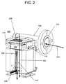
図2は、本発明の実施形態に係る並流装置を示す断面斜視図である。図2を参照しつつ説明すると、並流装置の概略を参照番号200で図示する。装置200の動作を説明すると、気体流は参照番号202で示されており、流体流は参照番号204で示されている。複数の個別供給ノズルバンク106は、互いに隣接するように配置されている。個別供給ノズルバンク106は、第1の側方チャネル110および第2の側方チャネル112に結合されている主要供給チャネル108を有する流体プレナムとの間で流体が連通するように構成されているノズルアレイを有する。当該装置は、チャンバ114と、気体流入口208と、気体流出口と、液体流入口120と、液体流出口とを備える。当該装置はさらに、米国特許出願第12/459,685号(発明の名称:「気液接触器ならびに排水清浄のシステムおよび方法」、出願日:2009年7月6日)に記載されているように気液分離器(不図示)を備える。当該米国特許出願の記載内容は全て、参照により本願に組み込まれる。個別供給ノズルバンクは、実質的に平面状の液体ジェット206を複数提供するように構成されている。各液体ジェットは、実質的に平面シート状の液体を含む。複数の液体ジェットは、互いに略平行な平面内に位置する。
FIG. 2 is a cross-sectional perspective view showing the parallel flow device according to the embodiment of the present invention. Referring to FIG. 2, a schematic of a cocurrent device is illustrated by
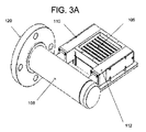
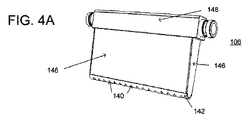
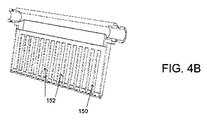
図3Aはノズル装置を示す斜視図である。図3Bは、図3Aのノズル装置を示す分解斜視図である。図4Aは、図3Bのノズルバンクを示す斜視図である。図4Bは、図4AのノズルバンクをラインA−A´に沿って示す断面図である。図5は、図4Bの個別供給ノズルバンクを示す底面図である。 FIG. 3A is a perspective view showing the nozzle device. FIG. 3B is an exploded perspective view showing the nozzle device of FIG. 3A. 4A is a perspective view showing the nozzle bank of FIG. 3B. 4B is a cross-sectional view showing the nozzle bank of FIG. 4A along line AA ′. FIG. 5 is a bottom view showing the individual supply nozzle bank of FIG. 4B.
図3Aから図5を参照しつつ説明すると、ノズル装置では、複数の個別供給ノズルバンク106が互いに隣接するように配置されている。個別供給ノズルバンク106は、第1の側方チャネル110および第2の側方チャネル112に結合されている主要供給チャネル108を有する流体プレナムとの間で流体が連通するように構成されているノズルアレイを有する。個別供給ノズルバンク106は、Oリング封止部材または関連技術分野で公知のその他の封止部材のような封止機構126によって、第1の側方チャネル110および第2の側方チャネル112に結合されている。本実施形態によると、第1の側方チャネル110は、第1の側方チャネルを利用可能とするためのアクセスプレート128を有する。第2の側方チャネル112も同様に、アクセスプレート130を有する。アクセスプレート(128、130)は、ネジ、リベット等の取着機構によって接続されている。言うまでも無く、アクセスプレート(128、130)はさらに、対応する側方チャネルに溶接されているとしてもよい。第1の側方チャネル110および第2の側方チャネル112は、接続箇所132において、ネジ、リベット、溶接等の取着機構によって主要供給チャネル108に結合されている。関連技術分野で公知のように、全ての接続箇所において封止層を用いて、例えば、可鍛性物質等の漏れを防ぐとしてよい。取着プレート134を用いて、当該ノズル装置を反応チャンバに結合するとしてよい。
Referring to FIGS. 3A to 5, in the nozzle device, a plurality of individual
図4Aから図5を参照しつつ説明すると、個別供給ノズルバンク106は、ステンレス鋼管142で形成された。管は、縦方向に半分に切断された。ノズル140は、管142に切り込みを入れて形成された。ノズル140の間隔144は、所望の用途に応じた適切な範囲内に収まる値であってよく、例えば、約1mm以上の範囲であってよい。好ましい実施形態では、約1cm以上であってよい。管には、複数のノズルを形成した。管142は、プレート146に取着、例えば、溶接された。プレート146は、供給本体148に取着された。この結果、チャンバが形成された。チャンバの長さが大きくなると、実施例を挙げて説明するが、ノズルの安定性が高くなり、ノズルの指向性が高くなる。チャンバの寸法は、適宜調整するとしてよい。
Referring to FIGS. 4A to 5, the individual
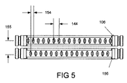
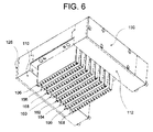
また、本実施形態によると、ジェットの品質を改善するべく、任意で分割部材を利用するとしてもよい。1以上の分割部材150を利用するとしてよい。分割部材150によって、図4Bのノズルバンクの断面図に示すように、複数の分離した供給チャネル152が形成されるとしてよい。図5および図6を参照しつつ説明すると、複数の個別供給ノズルバンクが利用されている様子が示されている。本実施形態によると、8個のノズルバンク(106、156、158、160、162、164、166、168)を組み合わせてアレイを構成した。当該アレイは、液体ジェット間を通過して、各ノズルアレイから気体が流出するように構成されている。言うまでも無く、個別ノズルバンクの数は、装置の規模および所望の気体流および速度に応じて、増減し得るとしてよい。
Moreover, according to this embodiment, in order to improve the quality of a jet, you may use a division member arbitrarily. One or more
また、本実施形態によると、隣接するノズルバンクのノズルは、互い違いになるように構成された。例えば、ノズルバンク106のノズルは、ノズルバンク156のノズルからオフセットされており、アレイ全体で交互にこのように配置されているので、隣接するノズルバンクの平坦なジェットは互い違いに位置することになる。隣接するノズルバンク間(中心線から中心線まで)の距離は、参照番号155で図示されており、範囲は約1.2以上であるとしてよい。隣接するノズル間の距離は、参照番号144で示されており、範囲は約1mmから約10mmまでであるとしてよい。隣接するノズルバンクのノズル同士の間の距離は、参照番号154で示されており、範囲は約0.5mmから約5mmまでであるとしてよい。言うまでも無く、さまざまな点で構成を変更するとしてよく、例えば、アレイを構成しているノズルバンクのうち隣接するノズルバンク間の距離を変更するとしてもよいし、ノズル間の距離を変更するとしてもよい。好ましい実施形態によると、このような構成要素間の距離は、等間隔である。
Further, according to the present embodiment, the nozzles of adjacent nozzle banks are configured to be staggered. For example, the nozzles in
<実施例>
<実施例1>
実施例1では、単一ジェット試験装置に基づき、通常動作条件下において水がノズルから流出する様子を説明した。当該装置は、図7Aから図7Cを参照しつつ説明する。
<Example>
<Example 1>
In Example 1, the manner in which water flows out of the nozzle under normal operating conditions has been described based on a single jet test apparatus. The apparatus will be described with reference to FIGS. 7A to 7C.
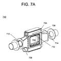
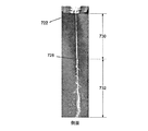
図7Aから図7Cを参照しつつ説明すると、当該装置の概略を参照番号700で示す。当該装置は、動作チャンバ702と、液体流入口704と、流体流出口708と、気体流入口713と、気体流出口714とを備える。流体流出口708は、再循環ループに接続されており、ポンプ(不図示)および流体流入口704に結合されている。ノズルプレート712の上方のプレナム709の流体圧を測定するべく、圧力ゲージ(不図示)を装着する。プレナムは、プレート712の上方に形成されている密閉されたチャンバであり、寸法は幅が226mm、高さは28.5mm、奥行きは20mmである。ノズルプレート712は、3個のノズルバンク714、716、および718を有する。この構成によると、各ノズルバンクにはノズルが3つ設けられている。具体的には、ノズルバンク716には、第1のノズル720、第2のノズル722、および、第3のノズル724が設けられている。ノズル同士の間は等間隔で離間しており、第1のノズル720と第2のノズル722との間の距離は4mmである。ノズルバンク714、716、および718は、等間隔に離間している。この実施例では、ノズルバンク714とノズルバンク716との間の距離は約5cmである。
Referring to FIGS. 7A to 7C, the apparatus is schematically indicated by
各ノズル(720、722、724)は、管(不図示)に切り込み深さ(DOC)を0.056インチとして切り込みを入れることによって形成された。この後、管を切断してプレートにレーザ溶接することによって、ノズルバンクを備えるプレートを形成した。管は、ステンレス鋼材料から形成されており、厚みは0.90mmであった。ノズルプレートは、ステンレス鋼材料から形成されており、厚みは4.72mmであった。各ノズルはまた、長径が2.67mmで短径が1.2mmとなるように形成される。この実施例によると、ノズルバンク714およびノズルバンク718は、ビーズ状の蝋、つまり、高融点のパラフィンで充填することによって塞いだ。さらに、ノズルバンク716については、ノズル720およびノズル724もまた、同じ蝋材料で充填して、ノズル722の1つのみを動作可能とした。プレート712はこの後、装置700内に図7Aに示すように配置された。液体プレナム709はプレート712の上方に配置され、プレート712全体を略水平方向に液体が流れるように構成される。ノズル722の開口と液体プレナムとの面積比は、約1:350となる。
Each nozzle (720, 722, 724) was formed by cutting a tube (not shown) with a cut depth (DOC) of 0.056 inches. Thereafter, the tube was cut and laser welded to the plate to form a plate with a nozzle bank. The tube was formed from a stainless steel material and had a thickness of 0.90 mm. The nozzle plate was formed from a stainless steel material and had a thickness of 4.72 mm. Each nozzle is also formed to have a major axis of 2.67 mm and a minor axis of 1.2 mm. According to this example,
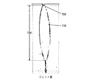
動作を説明すると、液体流入口704を用いて、外囲条件下の水道水をプレナム内に709に供給した。プレナム709内の圧力を示す圧力ゲージの値が約7psiとなった。図7Dは、実施例1で形成されるジェットの面を示す写真である。図7Eは、実施例1で形成されるジェットを側面からみた様子を示す写真である。
In operation, a
図7Dおよび図7Eを参照しつつ説明すると、水がノズル722から流出して、平坦なジェット725を形成する。ジェット725は、長さが約12cmとなるように形成される。この長さは、参照番号726で表される測定値である。ジェットの長さは、ノズルの流出口からジェットが底部で再び1つになる箇所までの距離を測定した値である。部分728に示すように、線形シート不安定性がこの部分から始まり、ジェットが分散し始めている。分散長さは、ジェットの分散が始まった箇所からの長さである。ジェットの安定領域は、参照番号730によって図示されている。不安定領域は、参照番号732で示されており、本明細書に記載するように複数のジェットの位置が互いに近接している場合に重要になる。
Referring to FIGS. 7D and 7E, water flows out of the
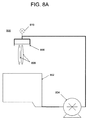
<実施例2>
実施例2によると、アレイ状のジェットは、図8Aに示す試験台装置によって形成された。当該システムの概略は、参照番号800で示す。当該システム800は、流体用排水ます802と、流体ポンプ804と、1つのノズルバンク806に接続されている配管設備を備える。流体は、再循環するようになっており、排水ます802からポンプへと流れてノズルバンク806を通過し、平坦なジェット808となった。平坦なジェット808は、排水ますに再び溜められた。ポンプから延びている配管網は、ノズルバンクのすぐ上流に接続されており、ノズルバンクの両側からの供給を可能とするように構成された。圧力ゲージ810は、流体経路のT字部分に配設され、ノズルバンクに供給される流体圧を測定した。
<Example 2>
According to Example 2, the array of jets was formed by the test bench apparatus shown in FIG. 8A. An overview of the system is indicated by
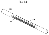
図8Bは、実施例2で用いたノズルバンクを示す図である。当該ノズルバンクの概略を、参照番号812で示す。ノズルバンク812は、長さが8インチで直径が0.5インチのステンレス鋼の管から形成された。この管の4インチの位置にある中央部分814は、幅が0.375インチの楕円を形成するように圧縮された。ノズルバンクには、複数のノズル816が設けられた。この実施例によると、ワイヤ放電加工(EDM)を用いて管に切り込みを入れて、32個のノズルを形成した。各ノズル816は、約2mmの等間隔で互いから離間させた。この実施例では、ノズルを1つおきにテープで塞いで、16個のノズルを利用したので、各ノズル間の距離は4mmとなった。
FIG. 8B is a diagram illustrating the nozzle bank used in the second embodiment. An outline of the nozzle bank is indicated by
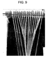
図9は、実施例2で形成されたジェットを示す写真である。 FIG. 9 is a photograph showing the jet formed in Example 2.
図9を参照しつつ説明すると、実施例2の装置の動作では、100%(w/w)のエチレングリコールを外囲温度でノズルバンクを通過させて流した。ノズルバンクの圧力を示す圧力ゲージ810の値は約11psiとなった。図9に示すように、内部ジェットは、ノズルバンク812の左側の1cmの格子スケールで表されているように、ノズルバンク812から約5cm離れた箇所で一点にまとまった。外側ジェットは、ノズルバンク812から約20cm離れた箇所で一点にまとまった。この実施例において、ジェットが一点に集中すると、ノズルバンクを互い違いになるように配置することに関して、問題が発生する。また、ジェットが一点に集まるために、ジェットの表面積は限られてしまっていた。
Referring to FIG. 9, in the operation of the apparatus of Example 2, 100% (w / w) ethylene glycol was passed through the nozzle bank at ambient temperature. The value of the
<実施例3>
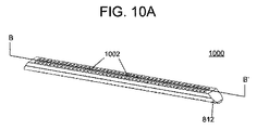
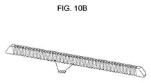
実施例3によると、実施例2の試験台装置によってアレイ状のジェットを形成した。この実施例では、ノズルバンク812は、図10Aから図10Bに示すチャネル挿入体で変更された。
<Example 3>
According to Example 3, an array of jets was formed by the test bench apparatus of Example 2. In this example, the
図10Aは、実施例3に係るチャネル挿入体を示す断面斜視図である。図10Bは、図10Aのチャネル挿入体をラインB−B´に沿って示す断面斜視図である。 FIG. 10A is a cross-sectional perspective view illustrating the channel insert according to the third embodiment. FIG. 10B is a cross-sectional perspective view showing the channel insert of FIG. 10A along line BB ′.
図10Aおよび図10Bを参照しつつ説明すると、チャネル挿入体の概略を参照番号1000で示す。チャネル挿入体1000は、ノズルバンク812の内壁に、反対側のノズルバンクの壁を利用して止めネジ(不図示)によって固定された。チャネル挿入体1000は、アルミニウムブロックから形成された。このブロックに、ノズルバンク812に形成されたノズルの開口と一致するような複数のチャネル1002を機械加工で形成した。チャネル挿入体に形成された個別チャネル1002は、幅が約0.039インチ、長さが約0.175インチ、奥行きが約0.19インチであった。チャネル挿入体の端部は、ノズルバンク内の流体の流れを容易にするべく斜めに形成され、片側は管の内部構造に合うように丸く形成されていた。本実施例によると、利用するノズルは5個で、残りのノズルはテープで塞いだ。ノズル間の間隔は4mmであった。
Referring to FIGS. 10A and 10B, a schematic of the channel insert is indicated by
図11は、実施例3で形成されたジェットを示す写真である。 FIG. 11 is a photograph showing the jet formed in Example 3.
図11を参照しつつ説明すると、実施例3に係る装置の動作では、チャネル挿入体1000を利用しつつ、100%(w/w)のエチレングリコールを外囲温度でノズルバンクを通過させて流した。ノズルバンクの圧力を示す圧力ゲージの値は、この実施例でも、11psiとなった。図示されているように、互いに平行で平坦なジェット1100が複数形成された。平坦なジェットの安定領域は名目上、15cmであった。ジェットは、安定領域より下方では、まとまりがなくなって互いに混ざり合う。この場合、ジェットが安定しているので、ジェットを互い違いに配置することができるようになる。
Referring to FIG. 11, in the operation of the apparatus according to the third embodiment, 100% (w / w) ethylene glycol is allowed to flow through the nozzle bank at the ambient temperature while using the
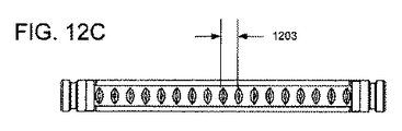
<実施例4>
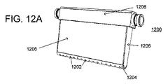
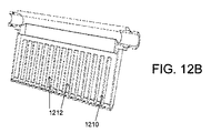
実施例4によると、アレイ状の平坦なジェットを実施例2で説明したシステムを用いて生成した。異なるノズルバンクを使用した。図12Aから図12Cを参照しつつ説明する。ノズルバンクの概略を、参照番号1200で示す。ノズルバンク1200は、直径が0.25インチのステンレス鋼管で形成された。この管は、長さが10cmで、長手方向に半分に切断された。ノズル1202は、上述したように、ワイヤEDMを利用して管1204に切り込みを入れて形成された。ノズル間の間隔1203は、図12Cに示すように、管に沿って約0.6cmであった。管には16個のノズルが形成された。この管をステンレス鋼製のプレート1206に溶接した。プレート1206は、機械加工されたステンレス鋼製の供給本体1208に溶接した。この結果、チャンバが形成された。供給管の中心線からノズル管までの距離は、約4cmであった。チャンバの幅は、テーパー形状を持つので、供給管の最上部においては1.016cmであり、ノズル管においては0.25インチとなった。ノズルバンク1200の内部には、ステンレス鋼製の分離部材1210を溶接した。各ノズル1402は、図8Bのノズルバンクの断面図に示したように、別個の供給チャネル1212を持つように構成された。このノズルバンクでは、各チャネルの高さは約1.21インチで、分離部材1210は約0.201インチの間隔で配置されている。
<Example 4>
According to Example 4, an array of flat jets was generated using the system described in Example 2. Different nozzle banks were used. This will be described with reference to FIGS. 12A to 12C. A schematic of the nozzle bank is indicated by
図12Dは、実施例4で形成されるジェットを示す写真である。 FIG. 12D is a photograph showing the jet formed in Example 4.
図12Dを参照しつつ説明すると、実施例4に係る装置の動作では、100%(w/w)のエチレングリコールを外囲温度でノズルバンクを通過させて流した。ノズルバンクの圧力を示す圧力ゲージの値は、この実施例でも、11psiとなった。図示されているように、互いに略平行で平坦なジェットが複数形成された。平坦なジェットの安定領域は名目上、15cmであった。ジェットは、安定領域より下方では、まとまりがなくなって互いに混ざり合う。この場合、ジェットが安定しているので、ジェットを互い違いに配置することができるようになる。 Referring to FIG. 12D, in the operation of the apparatus according to Example 4, 100% (w / w) ethylene glycol was allowed to flow through the nozzle bank at the ambient temperature. The value of the pressure gauge indicating the nozzle bank pressure was also 11 psi in this example. As shown in the figure, a plurality of flat jets substantially parallel to each other were formed. The stable area of the flat jet was nominally 15 cm. Below the stable region, the jets are mixed and mixed together. In this case, since the jets are stable, the jets can be arranged alternately.
また、この実施例では別の実験も行った。この実験では、分離部材1210を有さないノズルバンクを利用した。つまり、この構成によると、ノズルバンクは本例と同一であるが、分離部材1210が設けられなかった。平行なジェットを生成するためのノズルバンクの高さの最小値は5cmであり、高さが5cm未満になると平坦なジェットは、実施例2で示したように、1つにまとまってしまうことが観察された。
In this example, another experiment was also conducted. In this experiment, a nozzle bank without the separating
ノズルバンクの高さを5cmから8cmの間で設定した場合についても試験が行われた。つまり、供給管の中心線からノズル管までの距離が約5cmから約8cmで、内部分離部材1210は設けられなかった。ノズルバンクの高さを6cmとした場合にノズルバンクで形成されたジェットが、ノズルバンクの高さを5cmとした場合に形成されたジェットよりもわずかに平行である度合いが高いことが観察された。また、ノズルバンクの高さを6cm以上にして形成されたジェットは(ジェットの平行の度合いに関して)大きな改善は見られなかった。
The test was also conducted when the height of the nozzle bank was set between 5 cm and 8 cm. That is, the distance from the center line of the supply pipe to the nozzle pipe was about 5 cm to about 8 cm, and the
<実施例5>
実施例5によると、ジェット試験装置を用いて、水がノズルバンクアレイから流出して向流方向に流れている窒素ガスと相互作用する様子を説明する。当該装置は、図1に示す装置と同様に、動作チャンバと、流体プレナムと、気体流入口と、気体流出口と、流体プレナムに結合されている液体流入口と、流体流出口とを備えていた。
<Example 5>
Example 5 describes how water interacts with the nitrogen gas flowing out of the nozzle bank array and flowing in the countercurrent direction using a jet test device. Similar to the apparatus shown in FIG. 1, the apparatus includes an operating chamber, a fluid plenum, a gas inlet, a gas outlet, a liquid inlet coupled to the fluid plenum, and a fluid outlet. It was.
しかし、この実施例では、図13Aに示すように7個のノズルバンク(1302、1304、1306、1308、1310、1312、1314)をアレイ状にまとめて、各ノズルバンク間を気体が通過するように構成した。各ノズルバンクは、実施例4で説明したものであった。図13Aを参照しつつ説明すると、液体プレナムは、供給バンクのうち2つについて、支持部材1320に結合されている第1の供給プレナム1316および第2の供給プレナム1318を有していた。この実施例によると、各ノズルバンクには複数のノズル1322が形成された。図13Bを参照しつつ説明すると、バンク1302のノズルは、バンク1304のノズルとはオフセットされており、アレイ全体で交互にこのように配置されているので、図13Bに示すように、隣接するノズルバンクの平坦なジェットは互い違いに位置することになる。隣接するノズルバンク間(中心線から中心線まで)の距離は、参照番号1324で図示されており、この実施例では12.5mmあった。隣接するノズル間の距離は、参照番号1326で示されており、この実施例では6mmである。隣接するノズルバンクのノズル同士の間の距離は、参照番号1328で示されており、この実施例では3mmである。
However, in this embodiment, as shown in FIG. 13A, seven nozzle banks (1302, 1304, 1306, 1308, 1310, 1312, 1314) are arranged in an array so that gas passes between the nozzle banks. Configured. Each nozzle bank was as described in Example 4. Referring to FIG. 13A, the liquid plenum had a
ノズルバンクは、ノズルバンクを供給対象とする2つの側方プレナム(1316および1318)から成る供給プレナム内に配設されている。側方プレナムは、ステンレス鋼から機械加工で形成され、観察およびノズルバンク清浄のために取り外し可能なアクリル窓を含む。ノズルバンクは、Oリング1330を用いて側方プレナム内に封止されている。ノズルバンクおよび側方プレナムは、1つのステンレス鋼製の供給管(不図示)に取り付けられている。プレナム構造にはステンレス鋼製のフランジが取り付けられて、反応器の実装を可能とする。 The nozzle bank is disposed in a supply plenum consisting of two lateral plenums (1316 and 1318) to which the nozzle bank is supplied. The side plenum is machined out of stainless steel and includes a removable acrylic window for viewing and nozzle bank cleaning. The nozzle bank is sealed in the side plenum using an O-ring 1330. The nozzle bank and side plenum are attached to one stainless steel supply pipe (not shown). The plenum structure is fitted with a stainless steel flange to allow reactor mounting.
図13Cは、実施例5で形成されるジェットを示す写真である。図13Dは、実施例5で形成されるジェットを示す別の写真である。 FIG. 13C is a photograph showing the jet formed in Example 5. FIG. 13D is another photograph showing the jet formed in Example 5.
図13Cおよび図13Dを参照しつつ動作を説明すると、ノズルバンクアレイに水を流して、アレイ状の平坦で互い違いのジェットを生成する。流体プレナム上の圧力ゲージの測定値は、ノズルバンクに供給される圧力が11psiであった。図13Cは、向流がなく、真空環境下で動作する場合のジェットを示す。気体は、反応容器の底部で導入され、ジェットの流れと反対向きになるように流れ、ノズルバンク間を通って反応器外へと流出した。図13Dは、100Torr且つ13m/sで向流で窒素ガスを供給しつつ動作する場合のジェットを示す。このようなアレイの場合には、外囲雰囲気条件でも真空条件でもジェットが非常に安定することが観察された。上述した向流がジェットに対して導入される場合、ジェットの挙動にほとんど差異は見られなかった。ジェットの最上部の表面は、向流があっても、平坦なままであった。ジェットは、真空でも、上述した流れであっても、相互に作用したり1つにまとまることはなかった。 In operation, with reference to FIGS. 13C and 13D, water is passed through the nozzle bank array to produce an array of flat, staggered jets. The pressure gauge reading on the fluid plenum showed that the pressure supplied to the nozzle bank was 11 psi. FIG. 13C shows the jet when operating in a vacuum environment without counterflow. The gas was introduced at the bottom of the reaction vessel, flowed in the opposite direction of the jet flow, and flowed out of the reactor through the nozzle banks. FIG. 13D shows the jet when operating with a nitrogen flow in countercurrent at 100 Torr and 13 m / s. In the case of such an array, it was observed that the jet was very stable in both ambient and vacuum conditions. When the countercurrent described above was introduced to the jet, there was little difference in the behavior of the jet. The top surface of the jet remained flat despite the countercurrent. The jets did not interact or unite, whether in a vacuum or the flow described above.
当業者には、本発明の意図または範囲から逸脱することなく本発明をさまざまな点で変形および変更し得ることが明らかであろう。このため、本発明は、請求項およびその均等物の範囲内に含まれる限りにおいて、本発明の変形例および変更例も含むものことを意図している。 It will be apparent to those skilled in the art that various modifications and variations can be made in the present invention without departing from the spirit or scope of the invention. Thus, it is intended that the present invention include modifications and variations of this invention as long as they fall within the scope of the claims and their equivalents.
Claims (84)
前記チャンバに結合されている気体流入口と、
前記チャンバに結合されている気体流出口と、
前記反応チャンバに結合されている流体プレナムと、
個別供給ノズルバンクと、
前記反応チャンバに結合されている気体流体分離器と
を備え、
前記個別供給ノズルバンクは、前記液体プレナムに結合されているノズルアレイを有しており、前記ノズルアレイは、実質的に平面的な液体ジェットを複数提供し、前記複数の液体ジェットはそれぞれ、平面シート状の液体を含み、前記複数の液体ジェットは、実質的に平行な平面内に位置している装置。 A chamber;
A gas inlet coupled to the chamber;
A gas outlet coupled to the chamber;
A fluid plenum coupled to the reaction chamber;
Individual supply nozzle bank,
A gas fluid separator coupled to the reaction chamber;
The individual supply nozzle bank includes a nozzle array coupled to the liquid plenum, the nozzle array providing a plurality of substantially planar liquid jets, each of the plurality of liquid jets being planar. An apparatus comprising a sheet-like liquid, wherein the plurality of liquid jets are located in substantially parallel planes.
ノズルバンクと、
前記ノズルバンクに結合されている供給チャンバと
を有し、
前記チャンバは、
前記ノズルバンクに結合されている第1の側壁と、
前記ノズルバンクおよび前記第1の側壁に結合されている第2の側壁と、
前記ノズルバンクおよび前記第2の側壁に結合されている第3の側壁と、
前記ノズルバンク、前記第3の側壁、および前記第1の側壁に結合されている第4の側壁と
を含み、
前記第1の側壁、前記第2の側壁、前記第3の側壁および前記第4の側壁、ならびに、前記ノズルバンクは、前記ノズルバンクの反対側の端部に開口を持つチャンバを形成しており、前記開口は、流体が供給されるように構成されている供給管に結合されている請求項1に記載の装置。 The nozzle bank is
A nozzle bank,
A supply chamber coupled to the nozzle bank;
The chamber is
A first sidewall coupled to the nozzle bank;
A second sidewall coupled to the nozzle bank and the first sidewall;
A third sidewall coupled to the nozzle bank and the second sidewall;
The nozzle bank, the third sidewall, and a fourth sidewall coupled to the first sidewall;
The first side wall, the second side wall, the third side wall, the fourth side wall, and the nozzle bank form a chamber having an opening at an opposite end of the nozzle bank. The apparatus of claim 1, wherein the opening is coupled to a supply tube configured to be supplied with fluid.
前記複数のノズルに結合されている供給チャンバと、
前記供給チャネルに結合されている少なくとも1つの流入口と
を備え、
前記複数の液体ジェットはそれぞれ、平面シート状の液体を含み、前記複数の液体ジェットは実質的に平行な平面内に位置している個別供給ノズルバンク装置。 A plurality of nozzles providing a plurality of substantially planar liquid jets;
A supply chamber coupled to the plurality of nozzles;
And at least one inlet coupled to the supply channel;
Each of the plurality of liquid jets includes a flat sheet-like liquid, and each of the plurality of liquid jets is located in a substantially parallel plane.
前記ノズルバンクに結合されている第1の側壁と、
前記ノズルバンクおよび前記第1の側壁に結合されている第2の側壁と、
前記ノズルバンクおよび前記第2の側壁に結合されている第3の側壁と、
前記ノズルバンク、前記第3の側壁、および、前記第1の側壁に結合されている第4の側壁と
を有し、
前記第1の側壁、前記第2の側壁、前記第3の側壁、および、前記第4の側壁、ならびに、前記ノズルバンクは、前記ノズルバンクとは反対側の端部に開口を持つチャンバを形成しており、前記開口は、流体が供給されるように構成されている供給管に結合されている
請求項28に記載の装置。 The supply chamber comprises:
A first sidewall coupled to the nozzle bank;
A second sidewall coupled to the nozzle bank and the first sidewall;
A third sidewall coupled to the nozzle bank and the second sidewall;
The nozzle bank, the third sidewall, and a fourth sidewall coupled to the first sidewall;
The first side wall, the second side wall, the third side wall, the fourth side wall, and the nozzle bank form a chamber having an opening at an end opposite to the nozzle bank. 29. The apparatus of claim 28, wherein the opening is coupled to a supply tube configured to be supplied with fluid.
ノズルアレイを含む個別供給ノズルバンクを複数用いて、実質的に平面的な複数の液体ジェットを形成する段階と、
少なくとも1つの反応性または可溶性の気相分子を含む気体を供給する段階と、
前記気相分子と前記複数の液体ジェットとの間の物質移動相互作用によって前記気相分子の少なくとも一部を除去する段階と
を備え、
前記複数の液体ジェットはそれぞれ、平面シート状の液体を含み、前記複数の液体ジェットは実質的に平行な平面内に位置している方法。 A method of treating gas phase molecules with a gas-liquid contactor,
Forming a plurality of substantially planar liquid jets using a plurality of individually fed nozzle banks including a nozzle array;
Providing a gas comprising at least one reactive or soluble gas phase molecule;
Removing at least a portion of the gas phase molecules by mass transfer interaction between the gas phase molecules and the plurality of liquid jets;
Each of the plurality of liquid jets includes a planar sheet of liquid, and the plurality of liquid jets are located in substantially parallel planes.
請求項33に記載の方法。 34. Forming the plurality of equally spaced array of flat liquid jets includes forming the flat plurality of liquid jets at a hydraulic pressure within a range of about 2 psi to about 30 psi. The method described in 1.
ノズルアレイを含む個別供給ノズルバンクを複数用いて、実質的に平面的な複数の液体ジェットを形成する段階と、
少なくとも1つの反応性または可溶性の気相分子を含む気体を供給する段階と、
前記気相分子と前記複数の液体ジェットとの間の物質移動相互作用によって前記気相分子の少なくとも一部を除去する段階と
を備え、
前記複数の液体ジェットはそれぞれ、平面シート状の液体を含み、前記複数の液体ジェットは実質的に平行な平面内に位置しており、前記実質的に平面的な複数の液体ジェットは、水性スラリーで形成されている方法。 A method of treating gas phase molecules with a gas-liquid contactor,
Forming a plurality of substantially planar liquid jets using a plurality of individually fed nozzle banks including a nozzle array;
Providing a gas comprising at least one reactive or soluble gas phase molecule;
Removing at least a portion of the gas phase molecules by mass transfer interaction between the gas phase molecules and the plurality of liquid jets;
Each of the plurality of liquid jets includes a planar sheet-like liquid, the plurality of liquid jets are located in substantially parallel planes, and the substantially planar plurality of liquid jets is an aqueous slurry. The method that is formed in.
請求項58に記載の方法。 59. The method of claim 58, wherein at least one of the array of flat liquid jets has a thickness in the range of about 10 [mu] m to about 250 [mu] m.
ノズルアレイを含む個別供給ノズルバンクを複数用いて、複数の液滴が分布している不安定な液体ジェットを複数形成する段階と、
少なくとも1つの反応性または可溶性の気相分子を含む気体を供給する段階と、
前記気相分子と分布している前記複数の液滴との間の物質移動相互作用によって前記気相分子の少なくとも一部を除去する段階と
を備える方法。 A method of treating gas phase molecules with a gas-liquid contactor,
Forming a plurality of unstable liquid jets in which a plurality of liquid droplets are distributed using a plurality of individually supplied nozzle banks including a nozzle array;
Providing a gas comprising at least one reactive or soluble gas phase molecule;
Removing at least a portion of the gas phase molecules by mass transfer interactions between the gas phase molecules and the plurality of distributed droplets.
Applications Claiming Priority (9)
| Application Number | Priority Date | Filing Date | Title |
|---|---|---|---|
| US10056408P | 2008-09-26 | 2008-09-26 | |
| US10059108P | 2008-09-26 | 2008-09-26 | |
| US10060608P | 2008-09-26 | 2008-09-26 | |
| US61/100,606 | 2008-09-26 | ||
| US61/100,564 | 2008-09-26 | ||
| US61/100,591 | 2008-09-26 | ||
| US12/459,685 US7866638B2 (en) | 2005-02-14 | 2009-07-06 | Gas liquid contactor and effluent cleaning system and method |
| US12/459,685 | 2009-07-06 | ||
| PCT/US2009/058637 WO2010037043A1 (en) | 2008-09-26 | 2009-09-28 | Gas liquid contactor and method thereof |
Publications (2)
| Publication Number | Publication Date |
|---|---|
| JP2012504044A true JP2012504044A (en) | 2012-02-16 |
| JP2012504044A5 JP2012504044A5 (en) | 2013-06-06 |
Family
ID=42060131
Family Applications (3)
| Application Number | Title | Priority Date | Filing Date |
|---|---|---|---|
| JP2011529330A Withdrawn JP2012504044A (en) | 2008-09-26 | 2009-09-28 | Gas-liquid contactor and gas-liquid contact method |
| JP2011529325A Expired - Fee Related JP5740671B2 (en) | 2008-09-26 | 2009-09-28 | Gas-liquid contact device |
| JP2011529328A Withdrawn JP2012504043A (en) | 2008-09-26 | 2009-09-28 | Indirect and direct methods of isolating pollutants |
Family Applications After (2)
| Application Number | Title | Priority Date | Filing Date |
|---|---|---|---|
| JP2011529325A Expired - Fee Related JP5740671B2 (en) | 2008-09-26 | 2009-09-28 | Gas-liquid contact device |
| JP2011529328A Withdrawn JP2012504043A (en) | 2008-09-26 | 2009-09-28 | Indirect and direct methods of isolating pollutants |
Country Status (10)
| Country | Link |
|---|---|
| US (3) | US7866638B2 (en) |
| EP (3) | EP2358463A4 (en) |
| JP (3) | JP2012504044A (en) |
| KR (3) | KR20110091657A (en) |
| CN (3) | CN102215934A (en) |
| AU (3) | AU2009296248B2 (en) |
| CA (3) | CA2737798A1 (en) |
| MX (3) | MX2011003105A (en) |
| NZ (3) | NZ592101A (en) |
| WO (3) | WO2010037043A1 (en) |
Cited By (1)
| Publication number | Priority date | Publication date | Assignee | Title |
|---|---|---|---|---|
| WO2015072536A1 (en) * | 2013-11-14 | 2015-05-21 | 株式会社日本触媒 | Process for producing water-absorbing polyacrylic acid (salt) resin |
Families Citing this family (99)
| Publication number | Priority date | Publication date | Assignee | Title |
|---|---|---|---|---|
| FI121637B (en) * | 2004-07-23 | 2011-02-15 | Foster Wheeler Energia Oy | Method and apparatus for protecting a heat exchanger |
| US7987613B2 (en) * | 2004-10-12 | 2011-08-02 | Great River Energy | Control system for particulate material drying apparatus and process |
| US8398059B2 (en) | 2005-02-14 | 2013-03-19 | Neumann Systems Group, Inc. | Gas liquid contactor and method thereof |
| US7379487B2 (en) | 2005-02-14 | 2008-05-27 | Neumann Information Systems, Inc. | Two phase reactor |
| US7866638B2 (en) * | 2005-02-14 | 2011-01-11 | Neumann Systems Group, Inc. | Gas liquid contactor and effluent cleaning system and method |
| US8864876B2 (en) | 2005-02-14 | 2014-10-21 | Neumann Systems Group, Inc. | Indirect and direct method of sequestering contaminates |
| US8113491B2 (en) * | 2005-02-14 | 2012-02-14 | Neumann Systems Group, Inc. | Gas-liquid contactor apparatus and nozzle plate |
| WO2007026363A2 (en) * | 2005-09-01 | 2007-03-08 | Megair Ltd. | Method and apparatus for treating biologically contaminated air |
| KR20080085161A (en) * | 2005-12-14 | 2008-09-23 | 앳킨스 리미티드 | An extraction device |
| JP2010516606A (en) * | 2007-01-25 | 2010-05-20 | シエル・インターナシヨネイル・リサーチ・マーチヤツピイ・ベー・ウイ | Method for producing pressurized C02 flow at power plant combined with C02 capture unit |
| CN102170955A (en) * | 2008-07-31 | 2011-08-31 | 诺维信公司 | Modular reactor and process for carbon dioxide extraction |
| US8151482B2 (en) * | 2008-11-25 | 2012-04-10 | William H Moss | Two-stage static dryer for converting organic waste to solid fuel |
| CA2749121A1 (en) * | 2009-01-09 | 2010-07-15 | Codexis, Inc. | Carbonic anhydrase polypeptides and uses thereof |
| CA2760777C (en) * | 2009-05-15 | 2017-09-05 | Fmc Corporation | Combustion flue gas nox treatment |
| EP3287187A1 (en) | 2009-08-04 | 2018-02-28 | CO2 Solutions Inc. | Process for co2 capture using carbonates and biocatalysts |
| FR2951096B1 (en) * | 2009-10-09 | 2013-03-15 | Total Sa | PROCESS FOR OXIDATION OF ORGANIC COMPOUNDS |
| AU2010349824A1 (en) * | 2010-03-29 | 2012-10-25 | Roberto Tomas Miklos Ilkovics | Process for the removal of acid gases from the air and from combustion gases from burners and internal combustion engines by means of absorption with sodium hydroxide solution and process for obtaining sodium carbonate in order to acquire carbon credits |
| US8425662B2 (en) | 2010-04-02 | 2013-04-23 | Battelle Memorial Institute | Methods for associating or dissociating guest materials with a metal organic framework, systems for associating or dissociating guest materials within a series of metal organic frameworks, and gas separation assemblies |
| US20130244312A1 (en) * | 2011-10-26 | 2013-09-19 | Phillips 66 Company | Systems and methods for carbon dioxide absorption |
| US8608833B2 (en) * | 2010-06-09 | 2013-12-17 | Uop Llc | Selective absorption of gas components in co-current contacting apparatuses |
| AU2011272825A1 (en) | 2010-06-30 | 2013-01-10 | Codexis, Inc. | Chemically modified carbonic anhydrases useful in carbon capture systems |
| WO2012003299A2 (en) | 2010-06-30 | 2012-01-05 | Codexis, Inc. | Highly stable beta-class carbonic anhydrases useful in carbon capture systems |
| US8354261B2 (en) | 2010-06-30 | 2013-01-15 | Codexis, Inc. | Highly stable β-class carbonic anhydrases useful in carbon capture systems |
| WO2012006601A2 (en) * | 2010-07-08 | 2012-01-12 | Skyonic Corporation | Carbon dioxide sequestrations involving two-salt-based thermolytic processes |
| WO2012028418A1 (en) | 2010-09-02 | 2012-03-08 | Novacem Limited | Integrated process for producing compositions containing magnesium |
| WO2012030630A1 (en) | 2010-09-02 | 2012-03-08 | The Regents Of The University Of California | Method and system for capturing carbon dioxide and/or sulfur dioxide from gas stream |
| KR20130079553A (en) * | 2010-10-08 | 2013-07-10 | 샌트랄 글래스 컴퍼니 리미티드 | Halogen-containing gas supply apparatus and halogen-containing gas supply method |
| CN103347601B (en) | 2010-11-05 | 2015-04-22 | 国际热化学恢复股份有限公司 | Solids circulation system and method for capture and conversion of reactive solid |
| JP2012131697A (en) * | 2010-12-02 | 2012-07-12 | Nihon Univ | Immobilizing method of carbon dioxide |
| US20120177553A1 (en) * | 2010-12-07 | 2012-07-12 | Lindemann Scott H | Injector And Method For Reducing Nox Emissions From Boilers, IC Engines and Combustion Processes |
| US8580219B2 (en) | 2011-07-25 | 2013-11-12 | Coskata, Inc. | Ammonium recovery methods |
| US8486359B2 (en) | 2011-07-25 | 2013-07-16 | Coskata, Inc. | Ammonium recovery from waste water using CO2 acidified absorption water |
| EP2559476A1 (en) * | 2011-08-18 | 2013-02-20 | Siemens Aktiengesellschaft | Method and device for extracting volatile degradation products from the absorption circuit of a CO2 separation process |
| CN103958398B (en) | 2011-09-27 | 2016-01-06 | 国际热化学恢复股份有限公司 | Synthetic gas cleaning system and method |
| EP2596850A1 (en) * | 2011-11-28 | 2013-05-29 | ConocoPhillips Company | Solvent loading system |
| EP2785433A1 (en) | 2011-12-01 | 2014-10-08 | Statoil Petroleum AS | Process with continuously stirred tank reactor absorber and flash tank stripper |
| US8864879B2 (en) * | 2012-03-30 | 2014-10-21 | Jalal Askander | System for recovery of ammonia from lean solution in a chilled ammonia process utilizing residual flue gas |
| PL2890476T3 (en) * | 2012-08-30 | 2017-01-31 | Outotec Finland Oy | Method and apparatus for removing mercury from gas |
| CN103055636A (en) * | 2013-01-12 | 2013-04-24 | 孟钧 | Dust removing and air purifying device |
| EP2757071B1 (en) | 2013-01-17 | 2018-05-02 | General Electric Technology GmbH | Integrated carbon dioxide removal and ammonia-soda process |
| US12036509B2 (en) * | 2013-01-22 | 2024-07-16 | Stephen R. Temple | Methods and equipment for treatment of odorous gas streams |
| WO2014116310A1 (en) | 2013-01-25 | 2014-07-31 | Exxonmobil Upstream Research Company | Contacting a gas stream with a liquid stream |
| US9289721B2 (en) | 2013-02-27 | 2016-03-22 | Fuel Tech, Inc. | Process and apparatus for improving the operation of wet scrubbers |
| AR096078A1 (en) | 2013-05-09 | 2015-12-02 | Exxonmobil Upstream Res Co | SEPARATION OF IMPURITIES OF A GAS CURRENT USING A CONTACT SYSTEM IN VERTICALLY ORIENTED EQUICORRIENT |
| AR096132A1 (en) | 2013-05-09 | 2015-12-09 | Exxonmobil Upstream Res Co | SEPARATE CARBON DIOXIDE AND HYDROGEN SULFIDE FROM A NATURAL GAS FLOW WITH CO-CURRENT SYSTEMS IN CONTACT |
| WO2014205295A1 (en) * | 2013-06-20 | 2014-12-24 | New Fg Co., Llc | Method and apparatus for the removal of carbon dioxide from a gas stream |
| KR102096006B1 (en) * | 2013-09-26 | 2020-05-27 | 한국전력공사 | A Solvent Composition for Acid Gas Removal in Synthesis Gas of Integrated Gasification Combined Cycle |
| AU2014343383B2 (en) * | 2013-11-01 | 2019-01-31 | Vladimir Fedorov | Device and method for heat and mass exchange between gas and liquid |
| CN104147917B (en) * | 2014-07-30 | 2016-08-17 | 大唐国际发电股份有限公司高铝煤炭资源开发利用研发中心 | Fume desulphurization method |
| CN104297321B (en) * | 2014-09-28 | 2017-01-18 | 郑州轻工业学院 | Intelligent detection device of hydrogen sulfide generated by sludge aerobic fermentation |
| SG11201704529RA (en) | 2015-01-09 | 2017-07-28 | Exxonmobil Upstream Res Co | Separating impurities from a fluid steam using multiple co-current contactors |
| US9190114B1 (en) | 2015-02-09 | 2015-11-17 | Western Digital Technologies, Inc. | Disk drive filter including fluorinated and non-fluorinated nanopourous organic framework materials |
| SG11201705110QA (en) | 2015-02-17 | 2017-09-28 | Exxonmobil Upstream Res Co | Inner surface features for co-current contactors |
| ES2961349T3 (en) | 2015-02-23 | 2024-03-11 | Carbonfree Chemicals Holdings Llc | Carbon dioxide capture with magnesium hydroxide and magnesium hydroxide regeneration |
| MX2017011064A (en) | 2015-03-13 | 2017-11-10 | Exxonmobil Upstream Res Co | Coalescer for co-current contactors. |
| KR101709865B1 (en) * | 2015-09-23 | 2017-02-23 | 한국전력공사 | Method for producing sodium bicarbonate with high efficiency |
| WO2017083046A1 (en) * | 2015-11-10 | 2017-05-18 | Aecom Technical Services, Inc | System and method for removal of impurities resulting from the use of soda ash in coal fired power plants |
| SG11201805953YA (en) * | 2016-01-21 | 2018-08-30 | Squaretail Pty Ltd | Method and apparatus for removing carbon dioxide from flue gas |
| ES2940894T3 (en) | 2016-02-16 | 2023-05-12 | Thermochem Recovery Int Inc | Two-stage integrated power product gas generation system and method |
| US10286431B1 (en) | 2016-03-25 | 2019-05-14 | Thermochem Recovery International, Inc. | Three-stage energy-integrated product gas generation method |
| US10913030B2 (en) | 2016-06-15 | 2021-02-09 | Yissum Research Development Company Of The Hebrew University Of Jerusalem Ltd. | Process for removing pollutants from a flue gas |
| JP6740036B2 (en) | 2016-06-30 | 2020-08-12 | 株式会社東芝 | Carbon dioxide recovery system and exhaust gas treatment method |
| CN106281467A (en) * | 2016-08-29 | 2017-01-04 | 湖南普丝环保能源有限公司 | Refuse gasification processing means and method |
| US10364398B2 (en) | 2016-08-30 | 2019-07-30 | Thermochem Recovery International, Inc. | Method of producing product gas from multiple carbonaceous feedstock streams mixed with a reduced-pressure mixing gas |
| US10941497B2 (en) * | 2017-02-27 | 2021-03-09 | Honeywell International Inc. | Electrochemical carbon dioxide converter and liquid regenerator |
| CA3067338C (en) | 2017-06-15 | 2023-03-07 | Exxonmobil Upstream Research Company | Fractionation system using bundled compact co-current contacting systems |
| CN110997094B (en) | 2017-06-15 | 2021-11-30 | 埃克森美孚上游研究公司 | Fractionation system using compact co-current contacting system |
| MX2019014920A (en) | 2017-06-20 | 2020-02-07 | Exxonmobil Upstream Res Co | Compact contacting systems and methods for scavenging sulfur-containing compounds. |
| US9920926B1 (en) | 2017-07-10 | 2018-03-20 | Thermochem Recovery International, Inc. | Pulse combustion heat exchanger system and method |
| MX2020001415A (en) | 2017-08-21 | 2020-03-09 | Exxonmobil Upstream Res Co | Integration of cold solvent and acid gas removal. |
| CN109529541B (en) | 2017-09-21 | 2022-07-22 | 株式会社东芝 | Carbon dioxide absorbent and carbon dioxide separation and recovery device |
| GB2566716A (en) | 2017-09-22 | 2019-03-27 | Fjell Biodry As | Gas capture system |
| US10099200B1 (en) | 2017-10-24 | 2018-10-16 | Thermochem Recovery International, Inc. | Liquid fuel production system having parallel product gas generation |
| CN107551712B (en) * | 2017-10-27 | 2019-09-24 | 安乡晋煤金牛化工有限公司 | A kind of dust removal method and cyclone dust |
| US10836654B1 (en) * | 2017-10-31 | 2020-11-17 | U.S. Department Of Energy | Stable immobilized amine sorbents for removal of an organic contaminate from wastewater |
| WO2019126877A1 (en) * | 2017-12-27 | 2019-07-04 | Gis Gas Infusion Systems, Inc. | High-flow, high-pressure inline saturator system and method thereof |
| US10427948B2 (en) * | 2018-01-26 | 2019-10-01 | Ethan J. Novek | Systems and methods for ammonia recovery, acid gas separation, or combination thereof |
| FR3077996B1 (en) * | 2018-02-21 | 2020-02-21 | Suez Groupe | PROCESS FOR THE TREATMENT OF GASES AND ASSOCIATED TREATMENT UNIT |
| KR102064662B1 (en) * | 2018-03-17 | 2020-01-09 | 이상준 | Environmentally hazardous waste gas processing system and burner structure used thereof |
| BR112020022845A2 (en) * | 2018-05-08 | 2021-02-02 | Mineral Carbonation International Pty Ltd | mineral carbonation |
| CN109395558A (en) * | 2018-10-23 | 2019-03-01 | 临安恒绿环境科技有限公司 | A kind of liquid spray scrubber |
| WO2020154545A1 (en) * | 2019-01-23 | 2020-07-30 | Evapco, Inc. | Carbon capture tower |
| BR112022000813A2 (en) * | 2019-07-19 | 2022-03-08 | Phoenix Llc | Gas jet deflection in pressurized systems |
| WO2021083109A1 (en) * | 2019-10-31 | 2021-05-06 | 中国石油化工股份有限公司 | So2 adsorption material, preparation method therefor and application thereof, and method for removing so2 from flue gas containing so2 |
| US11808528B2 (en) | 2020-02-03 | 2023-11-07 | Hamilton Sundstrand Corporation | Evaporator with grooved channels and orifice inserts |
| US11512908B2 (en) | 2020-02-03 | 2022-11-29 | Hamilton Sundstrand Corporation | Evaporator with grooved channels |
| US11555157B2 (en) | 2020-03-10 | 2023-01-17 | Thermochem Recovery International, Inc. | System and method for liquid fuel production from carbonaceous materials using recycled conditioned syngas |
| CN115698599A (en) * | 2020-05-21 | 2023-02-03 | 爱诺威信科技有限公司 | Method and device for purifying biological agents and volatile organic compounds from air |
| US11242785B2 (en) * | 2020-06-30 | 2022-02-08 | Saudi Arabian Oil Company | Process to capture SOx onboard vehicles and ships |
| US11466223B2 (en) | 2020-09-04 | 2022-10-11 | Thermochem Recovery International, Inc. | Two-stage syngas production with separate char and product gas inputs into the second stage |
| US12109531B2 (en) * | 2020-10-20 | 2024-10-08 | Qatar Foundation For Education, Science And Community Development | Process for hybrid carbon capture and mineralization |
| JP2024500840A (en) * | 2020-12-15 | 2024-01-10 | アイロベーション テクノロジーズ リミテッド | Method and apparatus for producing alkali bicarbonate and alkali carbonate |
| NL2028191B1 (en) * | 2021-05-11 | 2022-11-29 | Hovyu Holding B V | Method and system for CO2 capture |
| US11871730B2 (en) * | 2021-07-07 | 2024-01-16 | Innovasea | Multi-stage oxygen absorber insert for concurrent stripping of carbon dioxide |
| WO2023102165A1 (en) * | 2021-12-03 | 2023-06-08 | Michigan Technological University | SIMULTANEOUS REMOVAL OF CO2, NOx AND SOx USING SINGLE STAGE ABSORPTION COLUMN |
| CN114307555A (en) * | 2022-01-18 | 2022-04-12 | 广东德同环保科技有限公司 | Foaming gas tower |
| CN115403130B (en) * | 2022-09-19 | 2023-04-21 | 生态环境部南京环境科学研究所 | Device and process for repairing underground water based on in-situ chemical oxidation method |
| WO2024166673A1 (en) * | 2023-02-09 | 2024-08-15 | 国立大学法人 東京大学 | Carbon dioxide fixation composition |
| CN116407935B (en) * | 2023-06-12 | 2023-08-15 | 中国科学院大学 | Selective desulfurization method based on supergravity reactor |
Family Cites Families (129)
| Publication number | Priority date | Publication date | Assignee | Title |
|---|---|---|---|---|
| US441106A (en) * | 1890-11-18 | Santo | ||
| US1538457A (en) * | 1921-03-14 | 1925-05-19 | Zoelly Heinrich | Water-cooling device for condensers |
| US2484277A (en) * | 1944-10-25 | 1949-10-11 | Whiting Corp | Dust collector and sludge separator |
| BE498107A (en) * | 1946-11-08 | |||
| US2687614A (en) | 1947-02-01 | 1954-08-31 | Esther C Goddard | Fuel admission device for resonance combustion apparatus |
| US2631019A (en) * | 1949-10-18 | 1953-03-10 | Yates Alexander | Air washer and cooler |
| US3215415A (en) | 1960-10-19 | 1965-11-02 | Chemical Construction Corp | Gas-liquid contact apparatus |
| BE619761A (en) | 1961-07-05 | |||
| US3488924A (en) * | 1967-10-24 | 1970-01-13 | Effluent Controls Inc | Gas scrubber method |
| US3465504A (en) * | 1967-10-26 | 1969-09-09 | Esther Oropeza | Air purifier device |
| US3533560A (en) | 1968-02-12 | 1970-10-13 | Munters & Co Carl | Cooling tower spray nozzle |
| US3524630A (en) | 1968-07-01 | 1970-08-18 | Texaco Development Corp | Scrubbing nozzle for removing unconverted carbon particles from gas |
| US3582050A (en) | 1968-09-27 | 1971-06-01 | Nat Steel Corp | Fluid-handling,gas-scrubbing,and blast furnace top pressure control |
| US3607624A (en) * | 1969-08-22 | 1971-09-21 | Nekoosa Edwards Paper Co Inc | Self-cleaning deckle rail for papermaking machines |
| US3731461A (en) | 1970-04-07 | 1973-05-08 | Hamon Sobelco Sa | Drift eliminators for atmospheric cooling tower |
| JPS4848133A (en) | 1971-10-20 | 1973-07-07 | ||
| US3766489A (en) | 1972-02-07 | 1973-10-16 | Bell Telephone Labor Inc | Optical device, such as a dye laser, employing a free-flowing liquid stream |
| US3948608A (en) * | 1972-03-24 | 1976-04-06 | Weir Jr Alexander | Apparatus for treating stack gases |
| US3847714A (en) * | 1972-06-15 | 1974-11-12 | Dasi Industries | Method and apparatus for heat treating liqueform materials |
| US3932583A (en) | 1972-06-19 | 1976-01-13 | Texaco Inc. | Method of removing hydrogen sulfide from a gas containing carbon dioxide |
| US4026682A (en) | 1973-11-08 | 1977-05-31 | General Resource Corporation | Method of changing the length of a Venturi throat |
| US3914348A (en) * | 1974-02-25 | 1975-10-21 | Aerojet General Co | Platelet-venturi carburetor for combustion engine |
| US4099140A (en) | 1975-03-14 | 1978-07-04 | Minister Of National Defence | Chemical laser process and apparatus |
| US3984786A (en) | 1975-05-28 | 1976-10-05 | Jersey Nuclear-Avco Isotopes, Inc. | Nozzle for free jet dye laser |
| US4011287A (en) | 1975-07-11 | 1977-03-08 | David John Marley | Steam conditioning valve |
| US3985860A (en) | 1975-09-22 | 1976-10-12 | Pullman Incorporated | Method for oxidation of SO2 scrubber sludge |
| US4348432A (en) | 1976-04-08 | 1982-09-07 | Minnesota Mining And Manufacturing Company | Method for coating with radially-propagating, free, liquid sheets |
| US4073832A (en) * | 1976-06-28 | 1978-02-14 | Texaco Inc. | Gas scrubber |
| US4128206A (en) | 1977-05-31 | 1978-12-05 | Delavan Corporation | Low drift flat spray nozzle and method |
| US4310476A (en) * | 1979-04-12 | 1982-01-12 | Dasi Industries, Inc. | Apparatus for treating fluent materials |
| US4378236A (en) * | 1977-07-20 | 1983-03-29 | Helms Olin L | Method and apparatus for recovering heat and smoke from an airstream |
| US4340572A (en) | 1978-05-19 | 1982-07-20 | Woodside Construction, Inc. | Process for recovering heat from stack or flue gas |
| US4261511A (en) * | 1978-08-07 | 1981-04-14 | Erb Elisha | Nebulizer and method |
| US4246245A (en) | 1979-01-02 | 1981-01-20 | Bechtel International Corporation | SO2 Removal |
| US4269812A (en) | 1979-07-27 | 1981-05-26 | Pullman Incorporated | Horizontal cross-flow scrubber for sulfur oxide removal |
| US4343771A (en) * | 1979-07-27 | 1982-08-10 | Pullman Incorporated | Horizontal cross-flow scrubber |
| IT1133138B (en) * | 1979-09-28 | 1986-07-09 | Luwa Ag | PROCEDURE AND PLANT FOR AIR MOISTURIZING FOR THE CONDITIONING OF ROOMS |
| US4419301A (en) * | 1979-10-10 | 1983-12-06 | Dasi Industries, Inc. | Method and apparatus for treating fluent materials |
| US4314670A (en) * | 1980-08-15 | 1982-02-09 | Walsh William A Jun | Variable gas atomization |
| US4326553A (en) | 1980-08-28 | 1982-04-27 | Rca Corporation | Megasonic jet cleaner apparatus |
| US4284590A (en) | 1980-09-17 | 1981-08-18 | Respiratory Care, Inc. | Multiple aspirator for nebulizer |
| US4403324A (en) | 1981-05-26 | 1983-09-06 | Lexel Corporation | Dye laser having a dye jet nozzle which forms a well-defined dye stream, and its method of manufacture |
| FR2523019B1 (en) | 1982-03-15 | 1985-11-08 | Commissariat Energie Atomique | FLAT JET SANDBLASTING NOZZLE CONTAINING SOLID ABRASIVE PARTICLES, AND METHOD FOR IMPLEMENTING A SANDBLASTING NOZZLE FOR RADIOACTIVE DECONTAMINATION |
| US4507969A (en) | 1983-03-15 | 1985-04-02 | Martin Marietta Corporation | Ultrasonic liquid jet probe |
| US4828768A (en) * | 1983-06-10 | 1989-05-09 | Chevron Research Company | Jet scrubber and method of operation |
| US4740308A (en) | 1984-04-26 | 1988-04-26 | Champion International Corporation | Membrane cleaning process |
| DE3425092A1 (en) | 1984-07-07 | 1986-02-06 | SMS Schloemann-Siemag AG, 4000 Düsseldorf | METHOD AND DEVICE FOR COOLING CONTINUOUSLY DELIVERED Pouring Strands in a Continuous Casting Plant |
| US4668498A (en) | 1985-09-27 | 1987-05-26 | Davis James A | Supersonic singlet delta oxygen aerosol generator |
| US4810268A (en) * | 1985-11-07 | 1989-03-07 | Ppg Industries, Inc. | Apparatus and method of washing air |
| US4720290A (en) | 1985-11-08 | 1988-01-19 | Conoco Inc. | Reduction of liquid atomizer droplet size |
| US4968328A (en) | 1986-05-16 | 1990-11-06 | Duke Eddie D | De-mister baffle and assembly |
| US4744518A (en) | 1986-11-12 | 1988-05-17 | Can-Am Engineered Products, Inc. | Fan adjustment for paint spray gun |
| US4834288A (en) * | 1987-01-05 | 1989-05-30 | Tufts University | Pulsed slit nozzle for generation of planar supersonic jets |
| US4887100A (en) | 1987-01-10 | 1989-12-12 | Am International, Inc. | Droplet deposition apparatus |
| US5364604A (en) | 1987-03-02 | 1994-11-15 | Turbotak Technologies Inc. | Solute gas-absorbing procedure |
| US5565180A (en) | 1987-03-02 | 1996-10-15 | Turbotak Inc. | Method of treating gases |
| US4819878A (en) | 1987-07-14 | 1989-04-11 | The Babcock & Wilcox Company | Dual fluid atomizer |
| US4893754A (en) | 1987-11-13 | 1990-01-16 | Francisco Ruiz | Generation of flat liquid sheet and sprays by means of simple cylindrical orifices |
| US5269967A (en) | 1988-06-06 | 1993-12-14 | Achgill Robert F | Process for mitigating chemical aerosol clouds |
| US4913225A (en) | 1988-09-15 | 1990-04-03 | The United States Of America As Represented By The Administrator, National Aeronautics And Space Administration | Liquid sheet radiator apparatus |
| US4948402A (en) | 1988-12-09 | 1990-08-14 | Davis Water & Waste Industries, Inc. | Modular air scrubber system |
| DE3915210A1 (en) | 1989-05-10 | 1990-11-22 | Lechler Gmbh & Co Kg | TWO-MATERIAL FLAT-JET NOZZLE FOR SPRAYING LIQUIDS |
| US5057853A (en) | 1990-09-04 | 1991-10-15 | Xerox Corporation | Thermal ink jet printhead with stepped nozzle face and method of fabrication therefor |
| US5170727A (en) | 1991-03-29 | 1992-12-15 | Union Carbide Chemicals & Plastics Technology Corporation | Supercritical fluids as diluents in combustion of liquid fuels and waste materials |
| KR100264382B1 (en) * | 1992-03-18 | 2000-08-16 | 폰투스 브레뎀 | Apparatus and method for gas cleaning or gas cooling |
| JPH05293332A (en) | 1992-04-21 | 1993-11-09 | Showa Shell Sekiyu Kk | Method for removing gas containing volatile organic compounds |
| US5395482A (en) | 1992-11-13 | 1995-03-07 | Fuji Photo Film Co., Ltd. | Ultra high purity vapor phase treatment |
| US5893943A (en) | 1993-07-26 | 1999-04-13 | Ada Environmental Solutions, Llc | Method and apparatus for decreased undesired particle emissions in gas streams |
| US5464154A (en) | 1993-09-29 | 1995-11-07 | Union Carbide Chemicals & Plastics Technology Corporation | Methods for spraying polymeric compositions with compressed fluids and enhanced atomization |
| US5419487A (en) * | 1993-09-29 | 1995-05-30 | Union Carbide Chemicals & Plastics Technology Corporation | Methods for the spray application of water-borne coatings with compressed fluids |
| DE4338585A1 (en) | 1993-11-11 | 1995-05-18 | Graef Jordt Steffen | Injector nozzle |
| US5392988A (en) | 1994-01-19 | 1995-02-28 | The United States Of America As Represented By The Secretary Of The Air Force | Uniform droplet generator |
| EP0671200B1 (en) | 1994-03-09 | 1998-08-12 | The Kansai Electric Power Co., Inc. | Method for the removal of carbon dioxide from combustion exhaust gas |
| US5643799A (en) | 1994-10-31 | 1997-07-01 | Umpqua Research Company | Process for analyzing CO2 in seawater |
| DE4439670A1 (en) | 1994-11-07 | 1996-05-09 | Bayer Ag | Process for the thermal oxidation of liquid waste |
| FR2732318B1 (en) * | 1995-03-31 | 1997-04-25 | Oreal | AEROSOL DISPENSER WITH TWO SPRAY NOZZLES |
| US5544571A (en) * | 1995-04-11 | 1996-08-13 | Dasi Corporation | Apparatus for treating fluent material |
| US5580531A (en) | 1995-06-07 | 1996-12-03 | Twenty-First Century Research Corporation | Devices for making reaction products by controlling transient conversion in an atomized liquid |
| DE19521688C2 (en) | 1995-06-14 | 1998-07-02 | Deutsch Zentr Luft & Raumfahrt | Oxygen iodine laser |
| US5655255A (en) | 1995-07-06 | 1997-08-12 | Bissell Inc. | Water extractor and nozzle therefor |
| US5639025A (en) * | 1995-07-07 | 1997-06-17 | The Procter & Gamble Company | High Viscosity pump sprayer utilizing fan spray nozzle |
| DE19541174C2 (en) | 1995-11-04 | 1998-11-26 | Spraying Systems Deutschland G | High performance jet nozzle |
| PL186336B1 (en) | 1996-02-01 | 2003-12-31 | Mitsubishi Heavy Ind Ltd | Apparatus for desulphurising exhaust gas |
| JPH09215918A (en) * | 1996-02-09 | 1997-08-19 | Kawasaki Heavy Ind Ltd | Gas-liquid reactor |
| US5700311A (en) | 1996-04-30 | 1997-12-23 | Spencer; Dwain F. | Methods of selectively separating CO2 from a multicomponent gaseous stream |
| US6010640A (en) | 1996-07-15 | 2000-01-04 | Boeing North American, Inc. | Salt free lithium hydroxide base for chemical oxygen iodine lasers |
| NO302454B1 (en) | 1996-07-31 | 1998-03-09 | Kvaerner Asa | Method of Carbon Dioxide Removal from Gases |
| US5837206A (en) | 1996-09-04 | 1998-11-17 | Boeing North American, Inc. | Integral manifold for a singlet delta oxygen generator |
| US5870422A (en) | 1997-07-09 | 1999-02-09 | Trw Inc. | Gain generator for high-energy chemical lasers |
| US5974072A (en) | 1997-07-09 | 1999-10-26 | Trw Inc. | High energy airborne coil laser |
| US6216765B1 (en) | 1997-07-14 | 2001-04-17 | Arizona State University | Apparatus and method for manufacturing a three-dimensional object |
| US6550751B1 (en) | 1997-11-26 | 2003-04-22 | Marsulex Environmental Technologies Corp. | Gas-liquid contactor with liquid redistribution device |
| US5947390A (en) | 1997-12-30 | 1999-09-07 | Smith; Gary L | Reduced emissions flow control plate |
| US6072820A (en) | 1998-04-16 | 2000-06-06 | The Boeing Company | Chemical oxygen iodine laser gain generator system |
| SE521301C2 (en) | 1998-12-08 | 2003-10-21 | Eftec Europe Holding Ag | sealing nozzle |
| US7021571B1 (en) | 1999-06-07 | 2006-04-04 | The Procter & Gamble Company | Spray device with flat fan nozzle |
| US6235177B1 (en) * | 1999-09-09 | 2001-05-22 | Aerogen, Inc. | Method for the construction of an aperture plate for dispensing liquid droplets |
| US6656253B2 (en) | 2000-05-18 | 2003-12-02 | The Procter & Gamble Company | Dynamic electrostatic filter apparatus for purifying air using electrically charged liquid droplets |
| US6875247B2 (en) | 2000-06-06 | 2005-04-05 | Battelle Memorial Institute | Conditions for fluid separations in microchannels, capillary-driven fluid separations, and laminated devices capable of separating fluids |
| US6459717B1 (en) | 2000-07-13 | 2002-10-01 | The United States Of America As Represented By The Secretary Of The Air Force | Continuous wave all gas phase iodine laser (AGIL) |
| US6722295B2 (en) * | 2000-09-29 | 2004-04-20 | Bert Zauderer | Method for the combined reduction of nitrogen oxide and sulfur dioxide concentrations in the furnace region of boilers |
| US6760406B2 (en) | 2000-10-13 | 2004-07-06 | Jettec Ab | Method and apparatus for generating X-ray or EUV radiation |
| US6843835B2 (en) | 2001-03-27 | 2005-01-18 | The Procter & Gamble Company | Air cleaning apparatus and method for cleaning air |
| US20040131531A1 (en) | 2001-04-20 | 2004-07-08 | Geerlings Jacobus Johannes Cornelis | Process for mineral carbonation with carbon dioxide |
| US6824071B1 (en) | 2001-08-27 | 2004-11-30 | Glas-Craft, Inc. | Gel-coat application method and apparatus |
| US6652624B2 (en) | 2001-10-10 | 2003-11-25 | Taiwan Semiconductor Manufacturing Co., Ltd. | Self-cleaning nozzles of wet scrubber |
| US6726187B2 (en) * | 2001-10-30 | 2004-04-27 | Hydrogenics Corporation | Humidifier |
| US6938434B1 (en) | 2002-01-28 | 2005-09-06 | Shields Fair | Cooling system |
| JP3957640B2 (en) * | 2002-02-21 | 2007-08-15 | アイシン化工株式会社 | Wide slit nozzle and coating method with wide slit nozzle |
| EP1509328A2 (en) | 2002-05-16 | 2005-03-02 | Graeme Stewart Shortis | Particle separation |
| US7116696B2 (en) | 2002-06-10 | 2006-10-03 | Ksy Corporation | Efficient method and apparatus for generating singlet delta oxygen at an elevated pressure |
| US6830608B1 (en) * | 2002-06-28 | 2004-12-14 | Jaeco Technology, Inc. | Apparatus for contacting large volumes of gas and liquid across microscopic interfaces |
| BRPI0309038B1 (en) | 2002-12-25 | 2018-05-15 | Kyoritsu Gokin Co., Ltd. | CAREPAS REMOVAL NOZZLE AND CARBURET NOZZLE |
| US6714570B1 (en) | 2002-12-27 | 2004-03-30 | General Atomics | Molecular iodine supply system for a chemical laser |
| US6832754B2 (en) | 2003-03-18 | 2004-12-21 | Alan Cross | Gas-liquid contactor |
| US7604787B2 (en) | 2003-05-02 | 2009-10-20 | The Penn State Research Foundation | Process for sequestering carbon dioxide and sulfur dioxide |
| US7163163B2 (en) * | 2003-07-07 | 2007-01-16 | Hypro, Llc | Wide angle nozzle for agricultural sprayers |
| KR101056101B1 (en) | 2003-07-09 | 2011-08-11 | 벨코테크놀러지스코오퍼레이션 | Wet cleaning device and method for controlling NOx emissions |
| KR20060115750A (en) * | 2003-11-13 | 2006-11-09 | 쉘 인터내셔날 리써취 마트샤피지 비.브이. | Feed nozzle assembly |
| JP2006160555A (en) * | 2004-12-07 | 2006-06-22 | Oyo Kogaku Kenkyusho | Liquid column type excited oxygen generation unit |
| US7820591B2 (en) | 2005-01-04 | 2010-10-26 | Korea Electric Power Corporation | Highly attrition resistant and dry regenerable sorbents for carbon dioxide capture |
| US7866638B2 (en) | 2005-02-14 | 2011-01-11 | Neumann Systems Group, Inc. | Gas liquid contactor and effluent cleaning system and method |
| US7379487B2 (en) | 2005-02-14 | 2008-05-27 | Neumann Information Systems, Inc. | Two phase reactor |
| US8113491B2 (en) * | 2005-02-14 | 2012-02-14 | Neumann Systems Group, Inc. | Gas-liquid contactor apparatus and nozzle plate |
| JP2006255629A (en) * | 2005-03-18 | 2006-09-28 | Mitsubishi Heavy Ind Ltd | Flue gas desulfurization apparatus |
| US7318855B2 (en) | 2005-03-30 | 2008-01-15 | The Boeing Company | Gas/liquid separation utilizing structured separator material |
| US20070085227A1 (en) | 2005-10-13 | 2007-04-19 | Tonkovich Anna L | Multi-phase contacting process using microchannel technology |
| US7219849B1 (en) | 2005-12-13 | 2007-05-22 | Graves Spray Supply, Inc. | Liquid impingement nozzle with paired openings |
| US7740002B2 (en) | 2006-09-05 | 2010-06-22 | Gm Global Technology Operations, Inc. | Fuel injector |
-
2009
- 2009-07-06 US US12/459,685 patent/US7866638B2/en not_active Expired - Fee Related
- 2009-09-28 EP EP20090817003 patent/EP2358463A4/en not_active Withdrawn
- 2009-09-28 NZ NZ592101A patent/NZ592101A/en not_active IP Right Cessation
- 2009-09-28 EP EP20090817006 patent/EP2349530A4/en not_active Ceased
- 2009-09-28 CA CA2737798A patent/CA2737798A1/en not_active Abandoned
- 2009-09-28 NZ NZ592098A patent/NZ592098A/en not_active IP Right Cessation
- 2009-09-28 MX MX2011003105A patent/MX2011003105A/en active IP Right Grant
- 2009-09-28 NZ NZ592099A patent/NZ592099A/en not_active IP Right Cessation
- 2009-09-28 AU AU2009296248A patent/AU2009296248B2/en not_active Ceased
- 2009-09-28 WO PCT/US2009/058637 patent/WO2010037043A1/en active Application Filing
- 2009-09-28 AU AU2009296242A patent/AU2009296242B2/en not_active Ceased
- 2009-09-28 MX MX2011003106A patent/MX2011003106A/en not_active Application Discontinuation
- 2009-09-28 MX MX2011003104A patent/MX335963B/en unknown
- 2009-09-28 WO PCT/US2009/058631 patent/WO2010037037A2/en active Application Filing
- 2009-09-28 CN CN2009801452357A patent/CN102215934A/en active Pending
- 2009-09-28 JP JP2011529330A patent/JP2012504044A/en not_active Withdrawn
- 2009-09-28 CA CA2737737A patent/CA2737737A1/en not_active Abandoned
- 2009-09-28 CN CN2009801457261A patent/CN102215935A/en active Pending
- 2009-09-28 KR KR1020117009443A patent/KR20110091657A/en not_active Application Discontinuation
- 2009-09-28 CN CN200980145931.8A patent/CN102215938B/en not_active Expired - Fee Related
- 2009-09-28 EP EP09817000A patent/EP2331233A4/en not_active Ceased
- 2009-09-28 CA CA2739237A patent/CA2739237A1/en not_active Abandoned
- 2009-09-28 KR KR1020117009420A patent/KR20110091656A/en not_active Application Discontinuation
- 2009-09-28 JP JP2011529325A patent/JP5740671B2/en not_active Expired - Fee Related
- 2009-09-28 AU AU2009296245A patent/AU2009296245B2/en not_active Ceased
- 2009-09-28 KR KR1020117009419A patent/KR20110091655A/en not_active Application Discontinuation
- 2009-09-28 JP JP2011529328A patent/JP2012504043A/en not_active Withdrawn
- 2009-09-28 WO PCT/US2009/058634 patent/WO2010037040A1/en active Application Filing
-
2010
- 2010-08-26 US US12/869,670 patent/US8105419B2/en not_active Expired - Fee Related
- 2010-08-26 US US12/869,619 patent/US8336863B2/en not_active Expired - Fee Related
Cited By (2)
| Publication number | Priority date | Publication date | Assignee | Title |
|---|---|---|---|---|
| WO2015072536A1 (en) * | 2013-11-14 | 2015-05-21 | 株式会社日本触媒 | Process for producing water-absorbing polyacrylic acid (salt) resin |
| US9682362B2 (en) | 2013-11-14 | 2017-06-20 | Nippon Shokubai Co., Ltd. | Process for producing water-absorbing polyacrylic acid (salt) resin |
Also Published As
Similar Documents
| Publication | Publication Date | Title |
|---|---|---|
| JP2012504044A (en) | Gas-liquid contactor and gas-liquid contact method | |
| US8323381B2 (en) | Two phase reactor | |
| US8216347B2 (en) | Method of processing molecules with a gas-liquid contactor | |
| US8668766B2 (en) | Gas liquid contactor and method thereof | |
| JP2012504044A5 (en) | ||
| CN1438916A (en) | Method for mixing fluids | |
| WO2010036436A1 (en) | Gas liquid contactor and effluent cleaning system and method | |
| JP2024500840A (en) | Method and apparatus for producing alkali bicarbonate and alkali carbonate | |
| KR101141169B1 (en) | Production system and method for gas hydrates using ultra-sonic vibrator | |
| US20230322569A1 (en) | Process and apparatus for producing alkali bicarbonates and alkali carbonates | |
| JPH0113897B2 (en) | ||
| RU100430U1 (en) | GAS-LIQUID REACTOR (OPTIONS) |
Legal Events
| Date | Code | Title | Description |
|---|---|---|---|
| A521 | Request for written amendment filed |
Free format text: JAPANESE INTERMEDIATE CODE: A523 Effective date: 20120330 |
|
| A621 | Written request for application examination |
Free format text: JAPANESE INTERMEDIATE CODE: A621 Effective date: 20120330 |
|
| A072 | Dismissal of procedure [no reply to invitation to correct request for examination] |
Free format text: JAPANESE INTERMEDIATE CODE: A073 Effective date: 20130806 |
|
| A300 | Application deemed to be withdrawn because no request for examination was validly filed |
Free format text: JAPANESE INTERMEDIATE CODE: A300 Effective date: 20130903 |