JP2012257150A - Stereoscopic video imaging device and stereoscopic video reproduction device - Google Patents
Stereoscopic video imaging device and stereoscopic video reproduction device Download PDFInfo
- Publication number
- JP2012257150A JP2012257150A JP2011130024A JP2011130024A JP2012257150A JP 2012257150 A JP2012257150 A JP 2012257150A JP 2011130024 A JP2011130024 A JP 2011130024A JP 2011130024 A JP2011130024 A JP 2011130024A JP 2012257150 A JP2012257150 A JP 2012257150A
- Authority
- JP
- Japan
- Prior art keywords
- osd
- unit
- imaging
- video signal
- eye video
- Prior art date
- Legal status (The legal status is an assumption and is not a legal conclusion. Google has not performed a legal analysis and makes no representation as to the accuracy of the status listed.)
- Pending
Links
Images


Landscapes
- Stereoscopic And Panoramic Photography (AREA)
- Testing, Inspecting, Measuring Of Stereoscopic Televisions And Televisions (AREA)
Abstract
Description
本発明は、観察者に適正観察距離を知覚させるためのOSDの生成を行う立体映像撮像装置および立体映像再生装置に関する。 The present invention relates to a stereoscopic video imaging apparatus and a stereoscopic video playback apparatus that generate an OSD for allowing an observer to perceive an appropriate observation distance.
視差を生じる左目用映像と右目用映像によって観察者に対し立体映像を知覚させる立体映像表示装置が脚光を浴びており、専用の立体映像コンテンツも多く製作されている。一方、家庭用ビデオカメラにおいても立体映像撮像機能を有するものが発表されており立体映像は広く一般に浸透しつつある。
表示画面上に表示した映像を観察者に立体映像として認識させるためには、左目用映像と右目用映像とが所定の位置関係を有する必要があるため、立体映像を撮像する場合には撮像した立体映像を観察する時の観察条件を考慮して左目用映像と右目用映像とが最適な位置関係になるように撮像装置の設定を行うことが必要になる。この設定には多くの条件項目を適切に組み合わせることになるため、家庭用立体ビデオカメラでは、例えば撮像した立体映像を観察する時の観察条件を入力するだけで、適切な撮像条件が自動的に設定される構成となることが望ましい。先行技術文献1には、撮像した立体映像を観察する時の画面サイズと観察距離を入力することで、撮像するカメラの姿勢角と画角を自動設定する立体カメラについて記載されている。
3D video display devices that allow viewers to perceive 3D video using left-eye video and right-eye video that generate parallax are in the limelight, and many dedicated 3D video contents have been produced. On the other hand, some home video cameras having a 3D image capturing function have been announced, and 3D images are spreading widely.
In order for the viewer to recognize the video displayed on the display screen as a stereoscopic video, the left-eye video and the right-eye video need to have a predetermined positional relationship. It is necessary to set the imaging device so that the left-eye video and the right-eye video have an optimal positional relationship in consideration of the observation conditions when observing the stereoscopic video. Since many condition items are appropriately combined with this setting, for example, in a home stereoscopic video camera, an appropriate imaging condition is automatically set simply by inputting an observation condition when observing a captured stereoscopic image. It is desirable that the configuration is set.
先行技術文献1に記載されたカメラの場合、設定された条件によって撮像画角が自動的に設定、つまり固定されることになるが、実際の撮像では設定された条件を変えてでも画角を変えた撮像を行ないたい場合がある。
In the case of the camera described in Prior
表示装置から観察者の目までの距離(以後、観察距離と称する)や表示装置のサイズや観察者の左目と右目の間隔(以後、眼間距離と称する)などの予め想定した観察条件に基づいて適切に設定した撮像条件とは異なる条件、例えば撮像画角を変更して撮像した映像を観察する場合、立体映像を最適な状態で観察することのできる観察距離が変わるため、これに合わせて観察者が観察距離を変えることができれば、より臨場感のある立体映像を観察することができる。しかし観察者は、今観察している位置での観察距離とは異なる距離が最適な観察距離である立体映像を見た場合、立体映像の不自然な遠近感を感じたとしても、どの距離で観察すべきかを知ることができない。
本発明では立体映像観察者に対し、撮像条件に応じた最適な観察距離を知覚させる立体映像撮像装置および立体映像再生装置を提供することを目的とする。
Based on presumed observation conditions such as the distance from the display device to the observer's eyes (hereinafter referred to as observation distance), the size of the display device, and the distance between the left and right eyes of the observer (hereinafter referred to as interocular distance). Therefore, when observing an image captured by changing the imaging angle of view, for example, when changing the imaging angle, the observation distance at which the stereoscopic image can be observed optimally changes. If the observer can change the observation distance, a more realistic stereoscopic image can be observed. However, if an observer sees a stereoscopic image whose optimum observation distance is a distance that is different from the observation distance at the current observation position, even if the viewer feels an unnatural perspective of the stereoscopic image, I can't know what to observe.
An object of the present invention is to provide a stereoscopic video imaging apparatus and a stereoscopic video playback apparatus that allow a stereoscopic video observer to perceive an optimal viewing distance according to imaging conditions.
本発明に係る立体映像撮像装置は上述の課題を解決するための手段として、立体映像を構成する左目用映像信号と右目用映像信号を生成する複数の撮像部(102L、102R)と、前記複数の撮像部の撮像画角を制御する撮像画角制御部(122)と、前記左目用映像信号と前記右目用映像信号それぞれに合成するためのOSD信号を生成するOSD生成部(146)と、前記撮像部から出力される前記左目用映像信号と前記右目用映像信号それぞれに前記OSD信号を所定時間合成するOSD合成部(106)と、前記OSD合成部から出力された、前記OSD信号が合成された左目用映像信号と右目用映像信号を合成し、立体映像データとして出力する信号処理部(108)と、表示画面サイズ情報とOSD表示距離情報と眼間距離情報を記憶する情報記憶部(130)と、撮像開始毎の撮像画角情報と、前記表示画面サイズ情報と、前記OSD表示距離情報と前記眼間距離情報に基づいて、前記OSD合成部にて合成される前記OSD信号に従って表示されるOSDの、前記左目用映像信号と前記右目用映像信号に従って表示される左目用映像上および右目用映像上のそれぞれの位置を設定するOSD視差設定部(144)とを備え、前記OSD合成部は前記OSD視差設定部で設定された位置に前記OSDを合成するように前記左目用映像信号及び前期右目用信号のそれぞれに前記OSD信号を合成することを特徴とする。 As a means for solving the above-described problems, a stereoscopic video imaging apparatus according to the present invention includes a plurality of imaging units (102L, 102R) that generate a left-eye video signal and a right-eye video signal constituting a stereoscopic video, An imaging field angle control unit (122) that controls an imaging field angle of the imaging unit, an OSD generation unit (146) that generates an OSD signal to be combined with the left-eye video signal and the right-eye video signal, An OSD synthesis unit (106) that synthesizes the OSD signal with each of the left-eye video signal and the right-eye video signal output from the imaging unit for a predetermined time, and the OSD signal output from the OSD synthesis unit is synthesized. The signal processing unit (108) that combines the left-eye video signal and the right-eye video signal, and outputs them as stereoscopic video data, display screen size information, OSD display distance information, and interocular distance information Is synthesized by the OSD synthesis unit on the basis of the information storage unit (130) that stores information, the imaging angle-of-view information for each imaging start, the display screen size information, the OSD display distance information, and the interocular distance information. OSD parallax setting unit (144) for setting the positions of the OSD displayed according to the OSD signal to be displayed on the left-eye video signal and the right-eye video displayed according to the left-eye video signal and the right-eye video signal And the OSD synthesis unit synthesizes the OSD signal with each of the left-eye video signal and the previous right-eye signal so as to synthesize the OSD at the position set by the OSD parallax setting unit. To do.
また本発明に係る立体映像撮像装置は上述の課題を解決するための手段として、前記撮像部が生成する前記左目用映像信号と前記右目用映像信号を、それぞれ所定時間格納しながら順次出力する映像記憶部(104)と、前記OSD合成部が前記OSDの合成を行なうタイミングを設定するタイミング設定部(123)とを更に備え、前記OSD合成部は、前記映像記憶部から出力される前記左目用映像信号と前記右目用映像信号それぞれに前記OSD信号を所定時間合成し、前記OSD視差設定部は、撮像開始毎に撮像画角が互いに異なる2つの連続した映像の内、時間的に後となる映像の前記撮像画角情報と、前記表示画面サイズ情報と、前記OSD表示距離情報と前記眼間距離情報に基づいて前記OSDの位置を設定するすることを特徴とする。 In addition, as a means for solving the above-described problem, the stereoscopic video imaging apparatus according to the present invention sequentially outputs the left-eye video signal and the right-eye video signal generated by the imaging unit while storing each for a predetermined time. A storage unit (104); and a timing setting unit (123) for setting a timing at which the OSD combining unit performs the OSD combining. The OSD combining unit outputs the left-eye output from the video storage unit. The OSD signal is combined with each of the video signal and the right-eye video signal for a predetermined time, and the OSD parallax setting unit is later in time among two consecutive videos having different imaging angles every time imaging is started. The position of the OSD is set based on the imaging field angle information of the video, the display screen size information, the OSD display distance information, and the interocular distance information. To.
また本発明に係る立体映像撮像装置は上述の課題を解決するための手段として、前記OSD視差設定部は、観察視野角度が前記撮像画角と同じ角度となる観察距離で観察したときに、立体映像として知覚するOSDの見かけ上の位置の観察者の目からの距離が前記OSD表示距離情報に関連した距離となるように前記OSDの位置を設定することを特徴とする。 In addition, as a means for solving the above-described problem, the stereoscopic image capturing apparatus according to the present invention is configured such that the OSD parallax setting unit performs stereoscopic viewing when observed at an observation distance where the observation viewing angle is the same as the imaging field angle. The position of the OSD is set such that the apparent position of the OSD perceived as an image from the observer's eyes is a distance related to the OSD display distance information.
また本発明に係る立体映像撮像装置は上述の課題を解決するための手段として、前記情報記憶部は撮像開始毎にその直前の撮像時の撮像画角情報を記憶し、前記OSD生成部は、2つの連続した映像の撮像画角を比較し、画角差が所定の値に対して大きい場合にOSDを生成することを特徴とする。 In addition, as a means for solving the above-described problem, the information storage unit stores imaging angle-of-view information at the time of immediately preceding imaging every time imaging starts, and the OSD generation unit The imaging field angles of two consecutive videos are compared, and the OSD is generated when the field angle difference is larger than a predetermined value.
また本発明に係る立体映像撮像装置は上述の課題を解決するための手段として、前記OSD生成部は、撮像画角が互いに異なる2つの連続した映像の撮像画角を比較し、時間的に前となる映像の撮像画角が大きい場合と時間的に後となる映像の撮像画角が大きい場合とで生成するOSDを切替えることを特徴とする。 In addition, as a means for solving the above-described problem, the stereoscopic image capturing apparatus according to the present invention compares the imaging field angles of two consecutive images having different imaging field angles, and compares the imaging field angles in time. The OSD to be generated is switched between a case where the imaging angle of view of the video to be large is large and a case where the imaging angle of view of the video later in time is large.
また本発明に係る立体映像撮像装置は上述の課題を解決するための手段として、前記タイミング設定部は、前記立体映像撮像装置の録画開始操作を基準としてOSDの合成タイミングを設定することを特徴とする。 The stereoscopic video imaging apparatus according to the present invention is characterized in that, as a means for solving the above-mentioned problem, the timing setting unit sets an OSD synthesis timing based on a recording start operation of the stereoscopic video imaging apparatus. To do.
また本発明に係る立体映像撮像装置は上述の課題を解決するための手段として、前記タイミング設定部は前記OSDの合成タイミングを、撮像画角が互いに異なる2つの連続した映像の切替わり時に対し、所定の第1の時間前から所定の第2の時間経過後までと設定し、前記所定の第1の時間および前記所定の第2の時間はそれぞれ0以上であって、前記所定の第1の時間と前記所定の第2の時間の合計は0ではないことを特徴とする。 In addition, as a means for solving the above-described problems, the stereoscopic image capturing apparatus according to the present invention is configured so that the timing setting unit determines the OSD synthesis timing when two consecutive images having different imaging angles of view are switched. The predetermined first time is set to the time after the predetermined second time elapses, and the predetermined first time and the predetermined second time are each 0 or more, and the predetermined first time The sum of the time and the predetermined second time is not zero.
また本発明に係る立体映像撮像装置は上述の課題を解決するための手段として、前記OSD生成部は前記表示画面サイズ情報と前記OSD表示距離情報の内、少なくとも一方に関連する情報を表わすOSDを生成することを特徴とする。 In addition, as a means for solving the above-described problem, the stereoscopic image capturing apparatus according to the present invention is configured such that the OSD generation unit displays an OSD representing information related to at least one of the display screen size information and the OSD display distance information. It is characterized by generating.
また本発明に係る立体映像撮像装置は上述の課題を解決するための手段として、前記表示画面サイズ情報と前記OSD表示距離情報を入力する操作部(118)を更に備えることを特徴とする。 The stereoscopic video imaging apparatus according to the present invention further includes an operation unit (118) for inputting the display screen size information and the OSD display distance information as means for solving the above-described problems.
また本発明に係る立体映像再生装置は上述の課題を解決するための手段として、左目用映像信号と右目用映像信号から構成され、少なくとも撮像画角情報を属性データとして合成した立体映像信号を入力する信号入力部と(150)、前記信号入力部に入力された前記立体映像信号の前記属性データを解析する属性データ解析部(306)と、前記左目用映像信号と前記右目用映像信号それぞれに合成するためのOSD信号を生成するOSD生成部(146)と、前記左目用映像信号と前記右目用映像信号それぞれに前記OSD信号を所定時間合成するOSD合成部(106)と、前記OSD合成部から出力された、前記OSD信号が合成された左目用映像信号と右目用映像信号を合成し、立体映像データとして出力する信号処理部(108)と、前記属性データ解析部が出力する前記撮像画角情報と、表示画面サイズ情報とOSD表示距離情報と眼間距離情報を記憶する情報記憶部(130)と、前記撮像画角情報と、前記表示画面サイズ情報と、前記OSD表示距離情報と前記眼間距離情報とに基づいて、前記OSD合成部にて合成される前記OSD信号に従って表示されるOSDの、前記左目用映像信号と前記右目用映像信号に従って表示される左目用映像上および右目用映像上のそれぞれの位置を設定する設定するOSD視差設定部を備え、前記OSD合成部は前記OSD視差設定部で設定された位置に前記OSDを合成するように前記左目用映像信号及び前記右目様映像信号のそれぞれに前記OSD信号を合成することを特徴とする。 In addition, as a means for solving the above-described problems, the stereoscopic video reproduction apparatus according to the present invention is configured with a left-eye video signal and a right-eye video signal, and inputs a stereoscopic video signal synthesized with at least imaging field angle information as attribute data. A signal input unit (150), an attribute data analysis unit (306) for analyzing the attribute data of the stereoscopic video signal input to the signal input unit, and the left-eye video signal and the right-eye video signal, respectively. An OSD generation unit (146) for generating an OSD signal for synthesis; an OSD synthesis unit (106) for synthesizing the OSD signal with each of the left-eye video signal and the right-eye video signal for a predetermined time; and the OSD synthesis unit The signal processing unit (108) that combines the left-eye video signal combined with the OSD signal and the right-eye video signal, which are output from, and outputs them as stereoscopic video data. An information storage unit (130) that stores the imaging field angle information output from the attribute data analysis unit, display screen size information, OSD display distance information, and interocular distance information; the imaging field angle information; Based on the display screen size information, the OSD display distance information, and the interocular distance information, the left-eye video signal and the right-eye signal of the OSD displayed according to the OSD signal synthesized by the OSD synthesis unit. An OSD parallax setting unit configured to set respective positions on the left-eye video and the right-eye video displayed according to the video signal, and the OSD composition unit sets the OSD at the position set by the OSD parallax setting unit. The OSD signal is synthesized with each of the left-eye video signal and the right-eye video signal so as to be synthesized.
本発明の立体映像撮像装置および立体映像再生装置によれば、立体映像観察者に対し、撮像条件に応じた最適な観察距離を知覚させることができる。 According to the stereoscopic video imaging apparatus and the stereoscopic video playback apparatus of the present invention, it is possible to make a stereoscopic video observer perceive an optimal observation distance according to imaging conditions.
以下、本発明の実施形態について、図面を参照して説明する。 Hereinafter, embodiments of the present invention will be described with reference to the drawings.
(実施形態1)
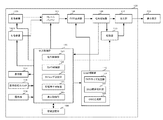
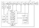
実施形態1における立体映像撮像装置の構成を図1に示す。
立体映像撮像装置100は、左撮像部102L、右撮像部102R、フレームバッファ104、OSD合成部106、信号処理部108、記録部110、出力部112、表示部114、画角切換スイッチ116、操作部118、中央制御部120、情報記憶部130、OSD制御部140で構成される。
中央制御部120は、操作制御部121、カメラ制御部122、タイミング設定部123、記録再生制御部124、表示制御部125で構成される。
OSD制御部140は、OSDサイズ設定部142、OSD視差設定部144、OSD生成部146で構成される。
(Embodiment 1)
FIG. 1 shows the configuration of the stereoscopic video imaging apparatus according to the first embodiment.
The stereoscopic
The
The
左撮像部102Lと右撮像部102Rは、それぞれ左目用映像信号と右目用映像信号の生成を行なう。左撮像部102Lは生成した左目用映像信号をフレームバッファ104に送る。同様に右撮像部102Rは生成した右目用映像信号をフレームバッファ104に送る。フレームバッファ104は映像信号を一時的に記憶するバッファメモリであり、受け取った映像信号の読み込みとOSD合成部106への送出を先入れ先出し的に順次行う。フレームバッファ104で映像信号を記憶する時間は、後述する予告表示時間よりも長い時間とする。フレームバッファ104で映像信号を記憶する時間は、予告表示時間の設定を元に中央制御部で制御する構成としても良いし、予告表示時間の最大設定値よりも長い固定値とする構成としても良い。
The
OSD合成部106は、OSD制御部140の指示するタイミングに従って左目用映像信号と右目用映像信号にそれぞれ、OSD制御部140が出力するOSD信号を合成し、信号処理部108に送る。信号処理部108は、OSD信号がそれぞれに合成された左目用映像信号と右目用映像信号を受け取り、それらを合成して、サイドバイサイドやトップアンドボトム等の1枚のフレームやフィールド内に左目用映像と右目用映像の面積を圧縮して組み合わせる方式や、左目用映像と右目用映像を走査線ごとに交互に組合せるラインシーケンシャル方式や、フレームやフィールドごとに左目用映像と右目用映像を時間軸で順番に組み合わせるフレームシーケンシャル方式、フィールドシーケンシャル方式等の他、表示装置に対応した各種方式に変換して立体映像信号を生成し、生成した立体映像信号を記録部110、出力部112、中央制御部120に送る。
The
記録部110はHDD、固体メモリーや取出し可能なディスク記録媒体や磁気テープ等とそれらに映像データを記録再生するしくみ等で構成され、記録再生制御部123から記録の指示を受けると、信号処理部108から受け取った立体映像信号を記録し、再生の指示を受けると、記録した立体映像信号を再生して出力部112に送出する。出力部112は立体映像信号を出力する。立体映像信号は表示装置200に入力され立体映像として表示される。表示装置200は立体映像を表示できる表示装置であって、それは3Dテレビや3Dモニター等である。
The
表示部114は映像モニター画面であり、信号処理部108から受け取った立体映像信号に基づき、撮影中の映像や再生中の映像を表示する。また、表示部114は、立体映像撮像装置の状態表示モニター画面、操作時のメニュー表示画面としても機能する。表示部114は裸眼立体表示モニターでも良く、立体表示機能を持たないものでも良い。表示部114は立体映像表示機能を持たない場合、左目用映像または右目用映像のみの表示や左目用映像または右目用映像により合成した二次元映像を表示する。画角切換スイッチ116は撮像画角を切換えるためのスイッチである。画角切換スイッチ116は画角設定情報を中央制御部120に送る。操作部118は押しボタン式スイッチや十字キー、タッチセンサ等で構成され、撮像者による操作入力および後述する撮像条件設定入力を受け付け、受け付けた情報を操作制御部121に送る。
The
操作制御部121は操作部118から受け取った操作入力情報を中央制御部内の各部に伝達する。カメラ制御部122は、左撮像部102Lと右撮像部102Rのそれぞれについて、画角、フォーカス、絞り等の調整を行う。タイミング設定部123は後述する手順で、OSDを生成するタイミングを設定する。記録再生制御部124は操作部118に入力された操作入力情報を元に、立体映像撮像装置100のモード制御を行う。
The
表示制御部125は立体映像撮像装置の状態や操作メニューを示す映像信号を生成して信号処理部108から受け取った立体映像信号や二次元映像信号と合成し、もしくは生成した映像信号のみ、または受け取った立体映像信号や二次元映像信号のみを切換えて表示部114に出力する。表示部114が立体映像表示機能を持つ場合、表示制御部125は立体映像撮像装置の状態や操作メニューを示す映像信号を立体表示対応の映像信号として生成しても良い。
情報記憶部130は立体映像撮像装置の設定内容を記憶するメモリで、不揮発性メモリで構成され、工場出荷時の初期設定値を記憶するとともに、操作部118から入力される立体映像立体映像撮像装置100の設定値を記憶する。
The
The
OSDサイズ設定部142はOSDサイズ情報と表示装置画面サイズ情報を制御部120から受け取り、後述する手順でOSDサイズを設定する。OSD視差設定部144は、撮像画角情報と表示装置の画面サイズ情報とOSD表示距離情報と眼間距離情報を制御部120から受け取り、後述する手順でOSDの表示画面上のずれ量を設定し、このずれ量となるように左目用映像と右目用映像のそれぞれに合成するOSDの表示画面上の位置を設定する。尚、OSDを観察する観察者に視差を生じさせるために左目用映像における表示画面上のOSDの表示位置と、右目用映像における表示装置上のOSDの表示位置が左右に異なる位置であるときに、OSDは表示画面上から飛び出し、もしくは奥まった位置にあるがごとく観察者は知覚する。この左右に異なる位置の間隔をOSDの表示画面上のずれ量と称する。OSD生成部146は、OSD表示内容情報を制御部120から受け取り、OSDサイズ設定部146からOSDサイズ情報を受け取り、OSD視差設定部144からOSDの表示画面上のずれ量の情報を受け取り、左目用映像信号に合成するOSD信号と右目用映像信号に合成するOSD信号をそれぞれ後述する手順で生成する。OSD生成部146は生成したそれぞれのOSD信号をOSD合成部106に送る。
The OSD
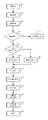
更に図2と図3を用いて、OSDの生成方法について詳しく説明する。図2はOSD生成の流れを説明するためのフローチャートである。図3は各種設定を行うための設定入力画面例である。
ステップS1で立体映像撮像装置100の電源が投入されると、立体映像撮像装置100は待機状態となる。ステップS2でユーザの操作に従い、各種設定が行われる。
Further, the OSD generation method will be described in detail with reference to FIGS. FIG. 2 is a flowchart for explaining the flow of OSD generation. FIG. 3 shows an example of a setting input screen for performing various settings.
When the power of the stereoscopic
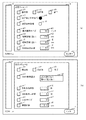
図3を用いて設定の内容を説明する。図3(a)のaは表示部114であり、設定入力のためのメニュー表示をしている状態を表わしている。bはタッチセンサであり、ユーザが触れた指をスライドさせることでメニュー内の選択項目が切換わる。cは押しボタンスイッチであり、目的とする項目を選択した状態でスイッチcを押すことで選択内容が決定される。ユーザーはタッチセンサbで項目を選択し、スイッチcを押して決定するという作業を繰り返すことで必要な設定入力を行う。タッチセンサbとスイッチcは操作部118の一部である。設定メニューは設定メニュー1と設定メニュー2で構成され、図3(a)は設定メニュー1を表示した例を、図3(b)は設定メニュー2を表示した例を示す。図3(a)と(b)で共通する部分には同じ記号を付与する。
The contents of the setting will be described with reference to FIG. In FIG. 3A, a represents a
図3(a)のd1前画面とd2次画面はメニュー画面の切替えを行う項目で、d1前画面またはd2次画面を選択して決定するとメニュー画面のページが切替わる。また、d3終了はメニュー画面を終了する項目で、d3終了を選択し決定するとメニュー表示を終了する。
e1設定はビデオカメラ、とf1設定は再生機、は立体映像撮像装置100のモードを切換える項目である。e1設定はビデオカメラを選択して決定すると、立体映像撮像装置100は撮像モードとなり、e2枠内の色が白から黒に変わり、撮像モードであることを示す。この時、f2枠内の色は白となる。図3(a)は撮像モードとなっている状態を示し、この状態で、図示しない記録開始ボタンを押すと撮像が開始される。f1設定は再生機、を選択して決定すると立体映像撮像装置100は再生モードとなり、f2枠内の色が白から黒に変わる。この時e2枠内の色は白となる。この状態で図示しない再生開始ボタンを押すと、撮像済み映像の再生が開始される。
The d1 previous screen and the d2 secondary screen in FIG. 3A are items for switching the menu screen. When the d1 previous screen or the d2 secondary screen is selected and determined, the menu screen page is switched. Further, d3 end is an item for ending the menu screen. When d3 end is selected and determined, the menu display is ended.
The e1 setting is an item for switching the mode of the stereoscopic
g1表示画面サイズは、撮像した立体映像を観察する表示装置の画面サイズを設定する項目である。bスクロールバーでg1表示画面サイズを選択してcエンターボタンを押すと画面サイズ選択状態になり、この状態でbスクロールバーを操作することでg2数値選択枠内の数値が切換わる。g2数値選択枠内の数値が設定したい値になった状態でcエンターボタンを押すと設定内容が入力される。図では現在、表示画面サイズが50インチの設定になっていることを示している。以下、選択枠を持つ項目の設定方法はg1表示画面サイズの設定方法と同様である。表示画面サイズの設定値はSとして情報記憶部130に記憶される。
The g1 display screen size is an item for setting the screen size of the display device for observing the captured stereoscopic video. When the g1 display screen size is selected with the b scroll bar and the c enter button is pressed, the screen size is selected, and the numerical value in the g2 numerical value selection frame is switched by operating the b scroll bar in this state. When the c enter button is pressed while the numerical value in the g2 numerical value selection frame is a value to be set, the setting contents are input. The figure shows that the display screen size is currently set to 50 inches. Hereinafter, the setting method of the item having the selection frame is the same as the setting method of the g1 display screen size. The set value of the display screen size is stored in the
h1観察距離(遠い)とi1観察距離(近い)は、撮像した立体映像を観察する観察者と表示装置との距離である観察距離の、想定する範囲を設定する項目である。撮像時には、ここで設定した範囲内の最適観察距離となる条件で撮像されるように制限される。観察距離の想定範囲を設定する目的は、例えば、撮像した映像を観察する表示装置が設置されている部屋の大きさなどの制約によって、例えば170cm以上離れて観察できない場合に、170cmを超える距離が最適観察距離である条件で撮像されることが無い様に制限するためである。本実施形態では、観察者が立体映像を有効に観察できる距離範囲となるように、観察距離(遠い)を170cm、観察距離(近い)を85cmと設定した。 The h1 observation distance (far) and the i1 observation distance (near) are items for setting an assumed range of the observation distance, which is the distance between the observer who observes the captured stereoscopic image and the display device. At the time of imaging, it is limited so that imaging is performed under the condition that the optimum observation distance is within the range set here. The purpose of setting the assumed range of the observation distance is, for example, a distance exceeding 170 cm when the observation distance cannot exceed 170 cm due to restrictions such as the size of the room in which the display device for observing the captured image is installed. This is to limit the image so as not to be imaged under the optimum observation distance. In the present embodiment, the observation distance (far) is set to 170 cm and the observation distance (near) is set to 85 cm so that the observer can effectively observe the stereoscopic image.
50インチの表示装置を観察距離170cmで観察すると、観察者が表示画面を観察する観察視野角度は、表示画面の対角線方向で約41度となる。一般に人間が普段集中している視野角度は約46度とされているので、観察距離(遠い)を170cmとした設定は適正であると言える。また、50インチの表示装置を観察距離85cmで観察すると観察者の観察視野角度は表示画面の対角線方向で74度となる。一般に、視野角度が約20度から約80度の範囲内では、視野角度の増大と共に臨場感が増すとされているため、観察距離85cmで観察することで、臨場感あふれる立体映像の観察が可能となる。観察距離(遠い)、観察距離(近い)の各設定値は情報記憶部130に記憶される。
When a 50-inch display device is observed at an observation distance of 170 cm, the viewing field angle at which the observer observes the display screen is about 41 degrees in the diagonal direction of the display screen. In general, since the viewing angle at which humans are usually concentrated is about 46 degrees, it can be said that setting the observation distance (far) to 170 cm is appropriate. When a 50-inch display device is observed at an observation distance of 85 cm, the viewing field angle of the observer is 74 degrees in the diagonal direction of the display screen. In general, when the viewing angle is within the range of about 20 degrees to about 80 degrees, it is said that the sense of reality increases as the viewing angle increases, so observing at an observation distance of 85 cm enables observation of stereoscopic images full of realism. It becomes. Each setting value of the observation distance (far) and the observation distance (near) is stored in the
j1OSD表示距離は、想定する観察条件で観察者がOSD画像を立体視した時の、観察者の目と立体映像として知覚するOSDの見かけ上の位置との距離を設定する項目である。本実施形態ではOSD表示距離を、観察者が手を伸ばした距離とすることを想定して57cmと設定した。OSD表示距離Laの設定値は情報記憶部130に記憶される。
The j1 OSD display distance is an item for setting a distance between the observer's eyes and the apparent position of the OSD perceived as a stereoscopic image when the observer stereoscopically views the OSD image under the assumed observation conditions. In this embodiment, the OSD display distance is set to 57 cm on the assumption that the observer extends his / her hand. The set value of the OSD display distance La is stored in the
図3(b)で、k1OSD表示選択は、OSD表示内容を選択する項目である。本実施形態では、連続する場面の撮像時の画角が大きく変化した場合にOSDを表示する。この時、前の場面に比較した後の場面の撮像時の画角が狭くなる場合と広くなる場合で表示内容を切換える。例えば後の場面の撮像時の画角が前の場面に比較して広くなる場合は「近くで見てね!」と表示し、狭くなる場合は「離れてみてね!」と表示する。k1OSD表示選択では、この表示の組み合わせを数種類用意されている中から選択する。例えば、表示画面サイズ情報やOSD表示位置情報も含めた表示形態を選択できる構成としても良い。 In FIG. 3B, k1 OSD display selection is an item for selecting the OSD display content. In the present embodiment, the OSD is displayed when the angle of view at the time of imaging of continuous scenes changes greatly. At this time, the display contents are switched depending on whether the angle of view at the time of imaging the scene after comparison with the previous scene is narrowed or widened. For example, if the angle of view of the subsequent scene is larger than that of the previous scene, “Please look closer!” Is displayed. If it is narrower, “Please look away!” Is displayed. In k1OSD display selection, the display combination is selected from several types. For example, a configuration in which a display form including display screen size information and OSD display position information can be selected is also possible.
表示画面サイズ設定を表示することで、実際の表示画面サイズと合っているか否か確認することができる。民生用ビデオカメラで撮像された映像コンテンツは、撮像後数十年の経過の後にもその再生映像を観察するものであって、撮像時に設定した表示画面サイズとは異なるサイズの表示装置で再生されることが考えられる。この場合でも、撮像時に設定した表示画面サイズとOSD表示距離が判ることで、最適観察距離における観察者が立体映像として知覚するOSDの観察者からの距離を、再生する表示画面サイズに応じて換算することができる。また、OSD表示距離設定を表示することで、どの位置にOSDを知覚する時に最適観察距離なのかを確認することができる。OSD表示選択設定は情報記憶部130に記憶される。OSD表示内容はデフォルトで1種類の組み合わせに決まっていて、変更できない構成としても良い。
By displaying the display screen size setting, it can be confirmed whether or not it matches the actual display screen size. Video content captured with a consumer video camera can be viewed after several decades after the image is captured, and is played back on a display device of a size different from the display screen size set at the time of imaging. It can be considered. Even in this case, by knowing the display screen size and OSD display distance set at the time of imaging, the distance from the observer of the OSD perceived as a stereoscopic image by the observer at the optimum observation distance is converted according to the display screen size to be reproduced. can do. Further, by displaying the OSD display distance setting, it is possible to confirm at which position the optimum observation distance is perceived when the OSD is perceived. The OSD display selection setting is stored in the
m1予告表示時間は、場面切替えの何秒前からOSDを表示するかを設定する項目である。予告表示時間は最短0秒から設定でき、最長で30秒位まで設定できれば十分である。n1切替え後表示時間は、場面切替え後に何秒間OSDの表示を続けるかを設定する項目である。切替え後表示時間は、最短0秒から設定でき、最長で30秒位まで設定できれば十分である。予告表示時間と切替え後表示時間はデフォルト値に決まっていて変更できない構成になっていても良い。予告表示時間と切替え後表示時間の設定値は情報記憶部130に記憶される。
The m1 notice display time is an item for setting how many seconds before the scene change to display the OSD. The notice display time can be set from a minimum of 0 seconds, and it is sufficient if it can be set up to a maximum of about 30 seconds. The display time after n1 switching is an item for setting how many seconds the OSD display continues after the scene switching. It is sufficient that the display time after switching can be set from 0 seconds at the shortest and about 30 seconds at the longest. The notice display time and the display time after switching are determined to default values and may not be changed. The setting values of the notice display time and the display time after switching are stored in the
p1OSDサイズは、OSDの表示サイズを設定する項目である。OSDの表示サイズは後述するように表示画面サイズによって適切なサイズに自動設定されるが、自動設定されたサイズに対し大きめにしたり小さめにしたい場合に、ある程度のサイズ変更ができる。サイズ設定は例えば大,中,小の3通りの選択ができ、中を選択すると自動設定されたサイズとなり、大または小を選択すると自動設定されたサイズに対して大きめまたは小さめのサイズになる。OSD表示サイズ設定は情報記憶部130に記憶される。
The p1OSD size is an item for setting the OSD display size. The OSD display size is automatically set to an appropriate size depending on the display screen size, as will be described later, but can be changed to some extent when it is desired to make it larger or smaller than the automatically set size. For example, the size setting can be selected from three types of large, medium, and small. When medium is selected, the size is automatically set, and when large or small is selected, the size is set larger or smaller than the automatically set size. The OSD display size setting is stored in the
r1眼間距離は、観察者の左目と右目の間の距離を設定する項目である。大人の眼間距離は約6.0cm、子供の場合は約5.0cmであるため、主に観察する観察者の眼間距離に合わせることが望ましい。また、この値は固定値とする設計としてもよい。眼間距離Wの設定値は情報記憶部130に記憶される。
The r1 interocular distance is an item for setting the distance between the left eye and the right eye of the observer. The distance between the eyes of an adult is about 6.0 cm, and that of a child is about 5.0 cm. Therefore, it is desirable to match the distance between eyes of the observer who mainly observes. In addition, this value may be designed to be a fixed value. The set value of the interocular distance W is stored in the
また、ユーザーは図示しない画角切換スイッチ116を操作して撮像画角の設定を行う。画角切換えスイッチ116は例えばスライドスイッチで、ある方向にスライドさせると画角が広くなる方向に撮像画角が変化し、逆の方向にスライドさせると画角が狭くなる方向に撮像画角が変化する様に中央制御部120が左撮像部102Lと右撮像部102Rを制御する構成になっている。中央制御部は画角切換スイッチ116の設定または左撮像部102Lと右撮像部102Rの撮像画角制御によって撮像画角設定値を得る。
In addition, the user operates an angle of view switch 116 (not shown) to set the imaging angle of view. The angle-of-
撮像画角切換え可能な範囲は、g1テレビ画面サイズの設定と、h1観察距離(遠い)およびi1観察距離(近い)で設定した観察距離範囲によって制限される。具体的には、g1テレビ画面サイズで設定した画面サイズを、h1観察距離(遠い)で設定した観察距離で観察した場合の観察画角の値と同じ値の撮像画角が最も狭い撮像画角として制限される。また、g1テレビ画面サイズで設定した画面サイズを、i1観察距離(近い)で設定した観察距離で観察した場合の観察画角の値と同じ値の撮像画角が最も広い撮像画角として制限される。撮像画角設定値はαとして情報記憶部130に記憶される。
The range in which the imaging angle of view can be switched is limited by the setting of the g1 television screen size and the observation distance range set by the h1 observation distance (far) and the i1 observation distance (near). Specifically, when the screen size set by the g1 TV screen size is observed at the observation distance set by the h1 observation distance (far), the imaging field angle having the same value as the observation field angle is the narrowest. As limited. In addition, when the screen size set by the g1 TV screen size is observed at the observation distance set by the i1 observation distance (close), the imaging field angle having the same value as the observation field angle value is limited as the widest imaging field angle. The The imaging field angle setting value is stored in the
以上のようにユーザーにより、表示画面サイズ(S)、観察距離(遠い)、観察距離(近い)、OSD表示距離(La)、OSD表示内容、予告表示時間,切替え後表示時間、OSDサイズ、撮像画角(α)、眼間距離(W)の設定が行われ、情報記憶部130のデータが更新される。この際、撮像画角設定値については前回撮像時の撮像画角の設定値をα0として残す。
As described above, the display screen size (S), observation distance (far), observation distance (near), OSD display distance (La), OSD display content, notice display time, display time after switching, OSD size, imaging by the user The angle of view (α) and the interocular distance (W) are set, and the data in the
図2に戻って説明する。
ステップS3で操作部118が、撮像開始のボタンが押されたと判断するとステップS4に進む。ステップS4では前回撮像時の撮像画角α0と今回の撮像画角αを比較し、その差が所定の値に対して大きいか小さいかを判定する。所定の差以下の場合(ステップS4/no)、ステップS14に進みOSDを生成せずにこのフローを終了する。所定の値よりも大きい場合(ステップS4/yes)、ステップS5に進む。
ステップS5では前回撮像時の撮像画角α0と今回の撮像画角αの大小関係を判定する。今回の撮像画角が前回の撮像画角に対し大きくなったと判定した場合(S5/yes)ステップS6に進み、観察者を近づける内容のOSDが選択される。小さくなったと判定した場合(S5/no)ステップS7に進み、観察者を遠ざける内容のOSDが選択される。
Returning to FIG.
If the
In step S5, the magnitude relationship between the imaging field angle α0 at the previous imaging and the current imaging field angle α is determined. When it is determined that the current imaging angle of view has become larger than the previous imaging angle of view (S5 / yes), the process proceeds to step S6, and the OSD with the content that brings the observer closer is selected. When it determines with having become small (S5 / no), it progresses to step S7 and the OSD of the content which keeps an observer away is selected.
次にステップS8に進む。ステップS8ではOSDのサイズ設定を行う。OSDサイズは基本的に、設定した表示画面サイズによって自動的に設定される。具体的には、表示画面サイズが大きい場合に画像全体に対するOSDの文字サイズの比率を小さくし、表示画面サイズが小さい場合に画像全体に対するOSDの文字サイズの比率を大きくする。例えば、50インチの場合にOSDの一つの文字の横幅が2cmだったとすると、同じ画像を画面サイズ100インチの表示画面で表示するとOSDの一つの文字の横幅は4cmとなり大きすぎるので、例えば3cmとなるように縮小し、同じ画像を画面サイズ25インチの表示画面で表示するとOSDの一つの文字の横幅は1cmとなり小さすぎるので、例えば1.5cmとなるように拡大設定する。 Next, the process proceeds to step S8. In step S8, the OSD size is set. Basically, the OSD size is automatically set according to the set display screen size. Specifically, the ratio of the OSD character size to the entire image is reduced when the display screen size is large, and the ratio of the OSD character size to the entire image is increased when the display screen size is small. For example, if the width of one character of OSD is 2 cm in the case of 50 inches, if the same image is displayed on a display screen having a screen size of 100 inches, the width of one character of OSD is 4 cm, which is too large. If the same image is displayed on a display screen with a screen size of 25 inches, the horizontal width of one character of the OSD is 1 cm which is too small, so that the enlargement is set to 1.5 cm, for example.
更に、設定入力の説明で記載したように、OSDサイズの切替えを行うことができる。OSDサイズを中に設定するとOSDサイズは上で説明したように設定した表示画面サイズによって自動的に標準に設定される。OSDサイズを大に設定すると標準サイズに対し少し拡大し、小に設定すると標準サイズに対し縮小される。たとえば中を選択したときに50インチの表示画面でOSDの一つの文字サイズの横幅が2cmだとすると、大を選択すると3cm、小を選択すると1.5cmとなるように設定される。 Further, the OSD size can be switched as described in the explanation of the setting input. When the OSD size is set to medium, the OSD size is automatically set to the standard according to the display screen size set as described above. When the OSD size is set to a large size, the standard size is slightly expanded, and when the OSD size is set to a small size, the standard size is reduced. For example, if the width of one OSD character size is 2 cm on the 50-inch display screen when the medium is selected, the size is set to 3 cm when the large is selected and 1.5 cm when the small is selected.
ステップS9でOSD視差設定部144は情報記憶部130から、表示画面サイズ(S),OSD表示距離(La),撮像画角(α)、眼間距離(W)の各設定値を読み出し、これらの値から左目用映像に合成するOSDと右目用映像に合成するOSDの表示画面上のずれ量を算出し設定する。図4を使って、OSDの視差設定ステップを説明する。図4(a)は撮像部の撮像画角をα度と設定して撮像している様子を示す。図では左撮像部の撮像画角のみ図示しているが、右撮像部の撮像画角も同様にα度である。図4(b)は、図4(a)で撮像した映像を50インチの表示装置に表示して、観察視野角度がα度になる位置で観察している様子を示す。図では左目の観察視野角度のみ図示しているが、右目の観察視野角度も同様にα度である。また説明を簡易とするために図4(a)の左撮像部と右撮像部の間の距離と図4(b)の観察者の左目と右目の間の距離はここではいずれもWとするが、左撮像部と右撮像部の間の距離はWと異なっても構わない。
In step S9, the OSD
表示画面サイズをS、観察視野角度をαとすると、観察距離Ldは式1で求めることができる。
Ld=S/(2×tan(α/2))・・・式1
本実施形態では、撮像時の画角と観察視野角度が同じ画角となる位置で観察した時に、立体映像として知覚するOSDの見かけ上の位置が観察者に対してOSD表示距離(La)だけ表示装置側になるようなOSDの表示画面上のずれ量を設定する。図4(c)はOSD表示距離がLaになるようにOSDの表示画面上のずれ量を設定した様子を示す。この時のOSDの表示画面上のずれ量bは式2で求めることができる。
b=W×(S/La/(tan(α/2))/2−1)・・・式2
また、OSDの表示画面上のずれ量の情報を元に左目用映像と右目用映像に表示するそれぞれのOSDについて、表示画面上の位置を設定する。
ステップS10でOSD生成部146は、ここまでのステップで決定したOSD表示内容情報,OSDサイズ情報,OSDの表示画面上の位置情報を元に、左目用映像信号と右目用映像信号に合成するOSD信号をそれぞれ生成して、OSD合成部106に出力する。
Assuming that the display screen size is S and the observation viewing angle is α, the observation distance Ld can be obtained by
Ld = S / (2 × tan (α / 2))
In the present embodiment, when an observation is performed at a position where the field angle at the time of imaging is the same as the viewing field angle, the apparent position of the OSD perceived as a stereoscopic image is the OSD display distance (La) with respect to the observer. A deviation amount on the display screen of the OSD is set so as to be on the display device side. FIG. 4C shows a state in which the shift amount on the OSD display screen is set so that the OSD display distance is La. The shift amount b on the display screen of the OSD at this time can be obtained by
b = W × (S / La / (tan (α / 2)) / 2-1)
Further, the position on the display screen is set for each OSD displayed on the left-eye video and the right-eye video based on the information on the shift amount on the OSD display screen.
In step S10, the
ステップS11でタイミング設定部123は、場面切替え前の映像信号に対するOSD合成タイミングを制御する。具体的にはタイミング設定部123は、情報記憶部130から予告表示時間の設定値を読み出し、フレームバッファ104L/104Rに記憶されている前回撮像した映像の終了時点から予告表示時間の設定値だけさかのぼったタイミング以降の画像信号にOSD画像信号を合成するためのタイミング信号をOSD制御部140に出力し、OSD制御部140はOSD合成部106を制御する。
In step S11, the
ステップS12でタイミング設定部123は、場面切換え後の映像信号に対するOSD合成タイミングを制御する。具体的には、タイミング設定部123は情報記憶部130から切換え後表示時間の設定値を読み出し、録画開始から切換え後表示時間の設定値に相当する時間、画像信号にOSD画像信号を合成するためのタイミング信号をOSD制御部140に出力し、OSD制御部140はOSD合成部106を制御する。撮像開始から切換え後表示時間の設定値だけ経過するとOSDの合成は終わり、ステップS13に進みこのフローは終了する。
In step S12, the
図5と図6を使って、実際のOSD表示例を説明する。
本実施形態では、撮像画角が異なる場面への切換えのタイミングで、適正観察距離を観察者に知覚させるためのOSD表示を行う。
図5は場面切換わり時にOSDを表示する例を示す図である。図6は、図5で示すOSDと観察者との位置関係を説明するための図である。図5の(a)〜(g)は連続した映像であり、(a)〜(b)を場面1、(c)〜(e)を場面2、(f)〜(g)を場面3とし、場面1と場面3の撮像画角を41度、場面2の撮像画角を74度とする。
尚、2つの連続した映像と表現する場合は、場面1と場面2の様に撮影画角が異なる場面の映像の連続を示す。
An actual OSD display example will be described with reference to FIGS.
In the present embodiment, OSD display for causing the observer to perceive an appropriate observation distance is performed at the timing of switching to a scene with a different imaging field angle.
FIG. 5 is a diagram showing an example of displaying the OSD when the scene is switched. FIG. 6 is a diagram for explaining the positional relationship between the OSD shown in FIG. 5 and the observer. (A) to (g) in FIG. 5 are continuous images, (a) to (b) being
Note that, when expressed as two consecutive images, it indicates a sequence of images of scenes having different shooting angles of view, such as
図6(a)は図5(a)の映像を、撮像画角と観察視野角度が等しくなる観察距離にて観察している様子を示す。このとき観察視野角度を41度、表示装置を50インチとすると式1より、観察距離は約170cmとなる。
場面2は場面1に対して撮像画角が広いので、場面2から場面1への切替わりのタイミングで、観察者を表示装置側に近づけるように誘導するOSDを表示する。図5(b)〜(c)は場面切換えのタイミングでOSDを表示している様子を示す。撮像画角は広くなる方向に切替わったので、OSD表示は「近づいて見てね!」と表示されている。この時、図6(b)に示すように、立体映像として知覚するOSDの見かけ上の位置は観察者から114cmの位置になり、観察者は立体映像として知覚するOSDの見かけ上の位置が設定した距離よりも遠いと知覚する。
FIG. 6A shows a state where the image of FIG. 5A is observed at an observation distance where the imaging field angle and the observation field angle are equal. At this time, when the observation viewing angle is 41 degrees and the display device is 50 inches, the observation distance is about 170 cm according to
Since
観察者がOSD表示内容に従って表示画面に近づき、立体映像として知覚するOSDの見かけ上の位置が観察者の目から57cmの距離になるように移動した状態を図6(c)に示す。この時の観察距離は85cmとなり、観察視野角度は撮像画角と同じ74度である。場面切換え後、所定の時間経過するとOSD表示は消え、図5(d)に示す映像となる。
場面3は場面2に対して撮像画角が狭いので、場面2から場面3への切替わりのタイミングで、観察者を表示装置から遠ざけるように誘導するOSDを表示する。図5(e)〜(f)は場面切換えのタイミングでOSDを表示している様子を示す。撮像画角は狭くなる方向に切替わったので、OSD表示は「離れてみてね!」と表示されている。この時、図6(d)に示すように、立体映像として知覚するOSDの見かけ上の位置は観察者から28.5cmの位置になり、観察者は立体映像として知覚するOSDの見かけ上の位置が設定した距離よりも近いと知覚する。
FIG. 6C shows a state in which the observer approaches the display screen according to the OSD display contents and moves so that the apparent position of the OSD perceived as a stereoscopic image is a distance of 57 cm from the eyes of the observer. The observation distance at this time is 85 cm, and the observation visual field angle is 74 degrees which is the same as the imaging field angle. After a scene change, the OSD display disappears when a predetermined time elapses, and the image shown in FIG.
Since scene 3 has a narrow imaging angle of view with respect to
観察者がOSD表示内容に従って表示画面から離れ、立体映像として知覚するOSDの見かけ上の位置が観察者から57cmの距離になるように移動した状態を図6(e)に示す。この時の観察距離は170cmとなり、観察視野角度は撮像画角と同じ41度である。場面切換え後、所定の時間経過するとOSD表示は消え、図5(g)に示す映像となる。OSDの表示タイミングは設定可能であり、場面切替わり前だけあるいは切替わり後だけとしても良い。 FIG. 6E shows a state in which the observer leaves the display screen according to the OSD display contents and moves so that the apparent position of the OSD perceived as a stereoscopic image is a distance of 57 cm from the observer. The observation distance at this time is 170 cm, and the observation visual field angle is 41 degrees which is the same as the imaging field angle. After a scene change, the OSD display disappears when a predetermined time elapses, and the image shown in FIG. The OSD display timing can be set, and may be set only before or after switching scenes.
以上のように実施形態1の立体映像撮像装置によれば、撮像画角に対応した適性観察距離で観察するように観察者を誘導するためのOSDを表示するので、観察者は場面ごとに適正な観察距離を認識することができ、適正観察距離で観察することで臨場感のある立体映像を観察することができる。また、フレームバッファによって映像信号を遅延させてからOSDを合成することで、場面切替え前にも場面切替え前後の撮像条件を反映したOSDを合成することができる。 As described above, according to the stereoscopic image capturing apparatus of the first embodiment, the OSD for guiding the viewer to observe at an appropriate observation distance corresponding to the imaging angle of view is displayed. An accurate observation distance can be recognized, and a realistic stereoscopic image can be observed by observing at an appropriate observation distance. Further, by synthesizing the OSD after delaying the video signal by the frame buffer, it is possible to synthesize the OSD reflecting the imaging conditions before and after the scene switching before the scene switching.
(実施形態2)
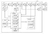
実施形態2における立体映像撮像装置の構成を図7に、立体映像再生装置の構成を図8に示す。図7および図8中で、図1と共通または類似する機能をもつ部分には図1と共通の符号を付け、説明を省略する。実施形態1の立体映像撮像装置100では撮像した映像信号にOSD信号を直接合成したが、実施形態2の立体映像撮像装置300では撮像時の設定情報を含む属性データを映像信号に合成して記録または伝送し、映像を表示装置に表示するときに属性データに基づいてOSDを生成して合成する。
実施形態2の立体映像撮像装置300では、実施形態1の立体映像撮像装置100に対し、属性データ生成部302、属性データ合成部304、属性データ解析部306、データ出力部308が追加されている。また、実施形態1の立体映像撮像装置100ではOSD生成部の後に位置していた記録部110が実施形態2の立体映像撮像装置300ではOSD合成部106より手前に位置している。
(Embodiment 2)
FIG. 7 shows the configuration of the stereoscopic video imaging apparatus according to the second embodiment, and FIG. 8 shows the configuration of the stereoscopic video playback apparatus. 7 and 8, parts having the same or similar functions as those in FIG. 1 are denoted by the same reference numerals as those in FIG. In the stereoscopic
In the stereoscopic
左撮像部102Lと右撮像部102Rは、それぞれ左目用映像信号と右目用映像信号の生成を行なう。左撮像部102Lは生成した左目用映像信号をフレームバッファ104に送る。同様に右撮像部102Rは生成した右目用映像信号をフレームバッファ104に送る。フレームバッファ104は映像信号を一時的に記憶するバッファメモリであり、受け取った映像信号の読み込みとOSD合成部106への送出を先入れ先出し的に順次行う。フレームバッファ104で映像信号を記憶する時間は、予告表示時間の設定を元に中央制御部で制御する構成としても良いし、予告表示時間の最大設定値よりも長い固定値とする構成としても良い。
The
属性データ生成部302は、撮像前にユーザによって設定更新された情報記憶部130の情報を元に属性データを生成し、属性データ合成部304に送る。属性データは、目的とするOSDを生成するために必要な情報で構成される。本実施形態では、少なくとも場面切替前の撮像画角情報(α0)と場面切替後の撮像画角情報(α)のそれぞれの情報を含めてコード化したものを属性データとする。
The attribute
属性データ合成部304は、フレームバッファ104から受け取った左目用映像信号と右目用映像信号に属性データ生成部302から受け取った属性データを合成して記録部110に送る。属性データを合成するタイミングは、OSDの予告表示時間設定値と切替後表示時間設定値に従ってタイミング設定部123により制御される。具体的にはタイミング設定部123は、情報記憶部130から予告表示時間の設定値と切替え後表示時間の設定値を読み出し、フレームバッファ104から受け取った映像信号の、場面切替え時点から予告表示時間の設定値だけさかのぼったタイミングから場面切替え後、切替え後表示時間の設定値まで属性データを合成するように属性データ合成部304を制御する。属性データ合成済みの映像信号は記録部110に送られる。
The attribute
記録部110は記録再生制御部124から記録の指示を受けると、受け取った信号を記録し、再生の指示を受けると記録してある信号を再生して属性データ解析部306およびデータ出力部308に送る。属性データ解析部306は受け取った信号に合成されている属性データを解析して解析結果を中央制御部120に送り、解析の終わった左目用映像信号と右目用映像信号をOSD合成部106に送る。
When the
中央制御部120は属性データ解析部306から受け取った情報を元にOSD制御部140にOSDの生成を指示する。OSD生成方法については基本的に実施形態1と同様であるが、OSD合成タイミングについては属性データが合成されているタイミングとなる。生成したOSD信号はOSD合成部106に送られる。OSD合成部106は属性データ解析部306から受け取った左目用映像信号と右目用映像信号にそれぞれOSD信号を合成して信号処理部108に送る。信号処理部108は受け取ったOSD合成済み左目用映像信号と右目用映像信号を合成して、立体映像信号を生成して出力部112に送る。出力部112は、受け取った立体映像信号を表示装置に対応した方式に変換し、出力する。出力した立体映像信号は外部の表示装置200に入力され、表示される。表示装置200は立体映像を表示できる装置で、3Dテレビ等である。
The
データ出力部308は、記録部110から受け取った属性データ合成済みの映像信号を外部に出力する。出力した映像信号は立体映像再生装置400に入力される。図8は立体映像再生装置400の構成を示すブロック図である。立体映像再生装置400は例えば立体映像撮像装置300に対し撮像機能を除いたものであり、外部から入力した属性データ合成済みの立体映像信号の属性データを解析して、解析結果に基づいてOSD信号を生成し、左目用映像信号と右目用映像信号のそれぞれにOSD信号を合成して表示装置に出力する機能を持つ。具体的には、立体映像再生装置400は立体映像撮像装置300に対し、左撮像部102L、右撮像部102R、フレームバッファ104、属性データ生成部302、属性データ合成部304、データ出力部308、表示部114、画角切換えスイッチ116、カメラ制御部122、表示制御部125を削除し、信号入力部150追加した構成になっている。図8中で図7と同一または類似の動作を行う部分には共通の符号をつけ、説明を省略する
立体映像再生装置400の信号入力部150は立体映像撮像装置300から属性データ合成済みの映像信号を受け取り、記録部110に伝送する。記録部110以降の信号の流れは立体映像撮像装置300の記録部110以降の信号の流れと同様である。
The
属性データには本実施例で示した情報以外に、表示画面サイズの設定値(S)、OSD表示選択設定情報、OSD表示距離の設定値(La)、OSDサイズ設定、眼間距離設定値(W)の情報を含め、再生時にこれらの設定を元にOSDを生成する構成としても良い。この場合も再生環境に設定値が変わるものについては再生時に設定変更できる構成とすることが望ましい。例えば、撮像した映像を記録しておいて、時間をおいて再生表示するような場合、再生する環境によって接続する表示装置の画面サイズが異なることが考えられる。このような場合、信号再生時に表示画面サイズの設定を実際に表示するサイズに書き換えることが有効である。表示画面サイズの書換えは操作部118によって行ない、情報記憶部130内の表示画面サイズを示すデータを更新し、OSD制御部140は更新された設定値に基づいてOSDを生成する。
また、OSD生成に関する計算を先に行い、その計算結果を属性データとして映像信号に合成する構成としても良い。この場合、再生環境によって設定変更を行うことが困難になるが、再生回路への負担を減らす効果がある。
In addition to the information shown in this embodiment, the attribute data includes a display screen size setting value (S), OSD display selection setting information, OSD display distance setting value (La), OSD size setting, and interocular distance setting value ( The OSD may be generated based on these settings at the time of reproduction including the information of (W). In this case as well, it is desirable to have a configuration in which the setting value can be changed at the time of reproduction when the setting value changes in the reproduction environment. For example, when the captured video is recorded and reproduced and displayed after a time, the screen size of the connected display device may differ depending on the reproduction environment. In such a case, it is effective to rewrite the display screen size setting to the actual display size during signal reproduction. The display screen size is rewritten by the
Alternatively, the calculation related to OSD generation may be performed first, and the calculation result may be combined with the video signal as attribute data. In this case, it is difficult to change the setting depending on the reproduction environment, but there is an effect of reducing the burden on the reproduction circuit.
以上のように実施形態2の立体映像撮像装置300および立体映像再生装置400によれば、撮像画角に対応した適性観察距離で観察するように観察者を誘導するOSDを表示するので、観察者は場面ごとに適正な観察距離を認識することができ、適正観察距離で観察することで臨場感のある立体映像を観察することができる。また、実施形態1の立体映像撮像装置のように映像信号に直接OSDを合成せず、撮像条件を示す属性データを撮像した映像信号に合成して、映像を表示する際に属性データに基づいてOSD信号を生成して合成するので、表示画面サイズ等の再生条件が撮影時に設定した内容と異なる場合にも最適なOSDを生成することができる。また、フレームバッファによって映像信号を遅延させてから属性データを合成することで、場面切替え前にも場面切替え前後の撮像条件を反映したOSDを合成することができる。
As described above, according to the stereoscopic
(実施形態3)
実施形態3における立体映像撮像装置の構成を図9に示す。図9は図7に対し、フレームバッファ104の位置が異なる。また、図7にあったデータ出力部308は、図9にはない。その他、図9中で図7と共通または類似する機能をもつ部分には図7と共通の符号を付け、説明を省略する。図7で説明した実施形態2の立体映像撮像装置300では、撮像した映像信号をフレームバッファ104に一時記憶させることで所定時間遅延させた後に属性データを合成した。実施形態3の立体映像撮像装置500では、撮像した映像信号を大きく遅延をさせることなく属性データを合成し、OSDを合成する直前で遅延させる。
(Embodiment 3)
FIG. 9 shows the configuration of the stereoscopic video imaging apparatus according to the third embodiment. FIG. 9 differs from FIG. 7 in the position of the
すなわち、OSD信号を映像信号に合成するタイミングは実施形態2では属性データが合成されているタイミングによって決めたが、本実施形態では実施形態1と同様にタイミング設定部123によって制御される。具体的には、タイミング設定部123は情報記憶部130から切替え後表示時間の設定値を読み出し、録画開始から切替え後表示時間の設定値に相当する時間、画像信号にOSD画像信号を合成するためのタイミング信号をOSD制御部140に出力し、OSD制御部140はOSD合成部106を制御する。
That is, the timing at which the OSD signal is combined with the video signal is determined by the timing at which the attribute data is combined in the second embodiment, but is controlled by the
本実施形態では、少なくとも場面切替え前の撮像画角情報(α0)、場面切替え後の撮像画角情報(α)、のそれぞれの情報を含めてコード化したものを属性データとする。また、実施形態2と同様に属性データには本実施例で示した情報以外に、表示画面サイズの設定値(S)、OSD表示選択設定情報、OSD表示距離の設定値(La)、OSDサイズ設定、眼間距離設定値(W)の情報を含め、再生時にこれらの設定を元にOSDを生成する構成としても良い。この場合も再生環境に設定値が変わるものについては再生時に設定変更できる構成とすることが望ましい。 In the present embodiment, at least the captured field angle information (α0) before scene switching and the captured field angle information (α) after scene switching are coded and included as attribute data. In addition to the information shown in the present embodiment, the attribute data includes display screen size setting value (S), OSD display selection setting information, OSD display distance setting value (La), and OSD size as in the second embodiment. It may be configured to generate the OSD based on these settings at the time of reproduction including information on the setting and the interocular distance setting value (W). In this case as well, it is desirable to have a configuration in which the setting value can be changed at the time of reproduction when the setting value changes in the reproduction environment.
以上のように実施形態3の立体映像撮像装置500によれば、撮像画角に対応した適性観察距離で観察するように観察者を誘導するOSDを表示するので、観察者は場面ごとに適正な観察距離を認識することができ、適正観察距離で観察することで臨場感のある立体映像を観察することができる。また、OSDを合成する前にフレームバッファ104によって映像信号を遅延させることで、実施形態2の立体映像撮像装置300と同様に、場面切替え前にも場面切替え前後の撮像条件を反映したOSDを合成することができる。
As described above, according to the stereoscopic
(実施形態4)
実施形態4における立体映像撮像装置の構成を図10に、立体映像再生装置の構成を図11に示す。実施形態3では立体映像撮像装置内にOSD生成機能を持っていたが、実施形態4では立体映像撮像部と立体映像再生部が分離した構成になっている。具体的には立体映像撮像装置600は立体映像撮像装置500に対し、属性データ解析部306、フレームバッファ104、OSD合成部106、出力部112、OSD制御部140、タイミング設定部123を削除し、データ出力部308を追加した構成になっている。立体映像再生装置700は立体映像撮像装置500に対し左撮像部102L、右撮像部102R、属性データ生成部302、属性データ合成部304、表示部114、画角切換スイッチ116、カメラ制御部122、表示制御部125を削除し、信号入力部150を追加した構成になっている。図10および図11で図9と共通または類似する機能を持つ部分には共通の符号を付け、説明を省略する。
(Embodiment 4)
FIG. 10 shows the configuration of the stereoscopic video imaging apparatus according to the fourth embodiment, and FIG. 11 shows the configuration of the stereoscopic video playback apparatus. In the third embodiment, the stereoscopic video imaging apparatus has an OSD generation function, but in the fourth embodiment, the stereoscopic video imaging unit and the stereoscopic video reproduction unit are separated. Specifically, the stereoscopic
図10の立体映像撮像装置600で記録部110までの信号処理は図9の立体映像撮像装置500と同様である。立体映像撮像装置600では記録部110からデータ出力部308に信号が伝送される。データ出力部308は受け取った信号を出力する。立体映像再生装置700の信号入力部150は立体映像撮像装置600から属性データ合成済みの映像信号を受け取り、受け取った信号を記録部110に伝送する。記録部110以降の信号処理は図9の記録部110以降と同様である。
Signal processing up to the
以上のように実施形態4の立体映像撮像装置600および立体映像再生装置700によれば、撮像画角に対応した適性観察距離で観察するように観察者を誘導するOSDを表示するので、観察者は場面ごとに適正な観察距離を認識することができ、適正観察距離で観察することで臨場感のある立体映像を観察することができる。また、立体映像再生装置700では、OSD合成直前でフレームバッファ104によって映像信号を遅延させることで、実施形態2と同様に、場面切替え前にも場面切替え前後の撮像条件を反映したOSDを合成することができる。
As described above, according to the stereoscopic
100、300、500、600 立体映像撮像装置
400、700 立体映像再生装置
102L 左撮像部
102R 右撮像部
104 フレームバッファ
106 OSD合成部
108 信号処理部
110 記録部
116 画角切換スイッチ
118 操作部
120 中央制御部
122 カメラ制御部
123 タイミング設定部
130 情報記憶部
140 OSD制御部
144 OSD視差設定部
146 OSD生成部
150 信号入力部
200 表示装置
302 属性データ生成部
304 属性データ合成部
100, 300, 500, 600 Stereoscopic
Claims (10)
前記複数の撮像部の撮像画角を制御する撮像画角制御部と、
前記左目用映像信号と前記右目用映像信号それぞれに合成するためのOSD信号を生成するOSD生成部と、
前記撮像部から出力される前記左目用映像信号と前記右目用映像信号それぞれに前記OSD信号を所定時間合成するOSD合成部と、
前記OSD合成部から出力された、前記OSD信号が合成された左目用映像信号と右目用映像信号を合成し、立体映像データとして出力する信号処理部と、
表示画面サイズ情報とOSD表示距離情報と眼間距離情報を記憶する情報記憶部と、
撮像開始毎の撮像画角情報と、前記表示画面サイズ情報と、前記OSD表示距離情報と前記眼間距離情報とに基づいて、前記OSD合成部にて合成される前記OSD信号に従って表示されるOSDの、前記左目用映像信号と前記右目用映像信号に従って表示される左目用映像上および右目用映像上のそれぞれの位置を設定するOSD視差設定部とを備え、
前記OSD合成部は前記OSD視差設定部で設定された位置に前記OSDを合成するように前記左目用映像信号及び前記右目様映像信号のそれぞれに前記OSD信号を合成することを特徴とする立体映像撮像装置。 A plurality of imaging units for generating a left-eye video signal and a right-eye video signal constituting a stereoscopic video;
An imaging angle-of-view control unit that controls the imaging angle of view of the plurality of imaging units;
An OSD generation unit that generates an OSD signal to be combined with each of the left-eye video signal and the right-eye video signal;
An OSD synthesis unit that synthesizes the OSD signal with each of the left-eye video signal and the right-eye video signal output from the imaging unit for a predetermined time;
A signal processing unit that synthesizes the left-eye video signal and the right-eye video signal, which are output from the OSD synthesis unit and synthesized with the OSD signal, and outputs them as stereoscopic video data;
An information storage unit for storing display screen size information, OSD display distance information, and interocular distance information;
The OSD displayed according to the OSD signal synthesized by the OSD synthesis unit based on the imaging angle-of-view information for each imaging start, the display screen size information, the OSD display distance information, and the interocular distance information. An OSD parallax setting unit for setting respective positions on the left-eye video and the right-eye video displayed according to the left-eye video signal and the right-eye video signal,
The OSD synthesis unit synthesizes the OSD signal with each of the left-eye video signal and the right-eye video signal so as to synthesize the OSD at the position set by the OSD parallax setting unit. Imaging device.
前記OSD合成部が前記OSDの合成を行なうタイミングを設定するタイミング設定部とを更に備え、
前記OSD合成部は、前記映像記憶部から出力される前記左目用映像信号と前記右目用映像信号それぞれに前記OSD信号を所定時間合成し、
前記OSD視差設定部は、撮像開始毎に撮像画角が互いに異なる2つの連続した映像の内、時間的に後となる映像の撮像画角情報と、前記表示画面サイズ情報と、前記OSD表示距離情報と前記眼間距離情報に基づいて、前記OSDの位置を設定する
ことを特徴とする請求項1記載の立体映像撮像装置。 A video storage unit for sequentially outputting the left-eye video signal and the right-eye video signal generated by the imaging unit while storing each of the video signal for a predetermined time;
A timing setting unit that sets a timing at which the OSD combining unit performs the OSD combining;
The OSD synthesis unit synthesizes the OSD signal with each of the left-eye video signal and the right-eye video signal output from the video storage unit for a predetermined time,
The OSD parallax setting unit is configured to capture imaging field angle information of a video that is temporally later among two consecutive videos having different imaging field angles each time imaging is started, the display screen size information, and the OSD display distance. The stereoscopic image capturing apparatus according to claim 1, wherein the position of the OSD is set based on information and the interocular distance information.
観察視野角度が前記撮像画角と同じ角度となる観察距離で観察したときに、立体映像として知覚するOSDの見かけ上の位置の観察者の目からの距離が前記OSD表示距離情報に関連した距離となるように前記OSDの位置を設定することを特徴とする
請求項2記載の立体映像撮像装置。 The OSD parallax setting unit
The distance from the observer's eye at the apparent position of the OSD perceived as a stereoscopic image when the observation viewing angle is the same as the imaging field angle is a distance related to the OSD display distance information The stereoscopic video imaging apparatus according to claim 2, wherein the position of the OSD is set so that
前記OSD生成部は、2つの連続した映像の撮像画角を比較し、画角差が所定の値に対して大きい場合にOSDを生成することを特徴とする
請求項1から3のいずれか1項に記載の立体映像撮像装置。 The information storage unit stores imaging angle-of-view information at the time of imaging immediately before imaging starts,
The OSD generation unit compares the imaging field angles of two consecutive videos, and generates an OSD when the field angle difference is larger than a predetermined value. The stereoscopic video imaging apparatus according to the item.
請求項4記載の立体映像撮像装置。 The OSD generation unit compares the imaging field angles of two consecutive videos having different imaging field angles, and takes a captured image of a temporally subsequent video and a temporally subsequent video. The OSD to be generated is switched between when the angle is large,
The stereoscopic video imaging apparatus according to claim 4.
前記立体映像撮像装置の録画開始操作を基準としてOSDの合成タイミングを設定することを特徴とする。
請求項1から5のいずれか1項に記載の立体映像撮像装置。 The timing setting unit includes:
The OSD composition timing is set based on the recording start operation of the stereoscopic image capturing apparatus.
The stereoscopic video imaging apparatus according to any one of claims 1 to 5.
請求項1から6のいずれか1項に記載の立体映像撮像装置。 The timing setting unit sets the composite timing of the OSD from before a predetermined first time to after a predetermined second time has elapsed with respect to switching of two consecutive images having different imaging angles of view, The predetermined first time and the predetermined second time are each greater than or equal to 0, and a sum of the predetermined first time and the predetermined second time is not zero. Item 7. The stereoscopic image capturing apparatus according to any one of Items 1 to 6.
請求項1から7のいずれか1項に記載の立体映像撮像装置。 The OSD generation unit generates an OSD representing information related to at least one of the display screen size information and the OSD display distance information.
The stereoscopic video imaging apparatus according to any one of claims 1 to 7.
請求項1から8のいずれか1項に記載の立体映像撮像装置。 The stereoscopic video imaging apparatus according to any one of claims 1 to 8, further comprising an operation unit that inputs the display screen size information and the OSD display distance information.
前記信号入力部に入力された前記立体映像信号の前記属性データを解析する属性データ解析部と、
前記左目用映像信号と前記右目用映像信号それぞれに合成するためのOSD信号を生成するOSD生成部と、
前記左目用映像信号と前記右目用映像信号それぞれに前記OSD信号を所定時間合成するOSD合成部と、
前記OSD合成部から出力された、前記OSD信号が合成された左目用映像信号と右目用映像信号を合成し、立体映像データとして出力する信号処理部と、
前記属性データ解析部が出力する前記撮像画角情報と、表示画面サイズ情報とOSD表示距離情報と眼間距離情報を記憶する情報記憶部と、
前記撮像画角情報と、前記表示画面サイズ情報と、前記OSD表示距離情報と前記眼間距離情報とに基づいて、前記OSD合成部にて合成される前記OSD信号に従って表示されるOSDの、前記左目用映像信号と前記右目用映像信号に従って表示される左目用映像上および右目用映像上のそれぞれの位置を設定する設定するOSD視差設定部を備え、
前記OSD合成部は前記OSD視差設定部で設定された位置に前記OSDを合成するように前記左目用映像信号及び前記右目様映像信号のそれぞれに前記OSD信号を合成することを特徴とする立体映像再生装置。 A signal input unit configured to input a stereoscopic video signal composed of at least imaging angle-of-view information as attribute data, comprising a left-eye video signal and a right-eye video signal;
An attribute data analysis unit that analyzes the attribute data of the stereoscopic video signal input to the signal input unit;
An OSD generation unit that generates an OSD signal to be combined with each of the left-eye video signal and the right-eye video signal;
An OSD synthesis unit that synthesizes the OSD signal with each of the left-eye video signal and the right-eye video signal for a predetermined time;
A signal processing unit that synthesizes the left-eye video signal and the right-eye video signal, which are output from the OSD synthesis unit and synthesized with the OSD signal, and outputs them as stereoscopic video data;
An information storage unit that stores the imaging field angle information output by the attribute data analysis unit, display screen size information, OSD display distance information, and interocular distance information;
Based on the imaging field angle information, the display screen size information, the OSD display distance information, and the interocular distance information, the OSD displayed according to the OSD signal synthesized by the OSD synthesis unit, An OSD parallax setting unit for setting the positions on the left-eye video and the right-eye video displayed according to the left-eye video signal and the right-eye video signal;
The OSD synthesis unit synthesizes the OSD signal with each of the left-eye video signal and the right-eye video signal so as to synthesize the OSD at the position set by the OSD parallax setting unit. Playback device.
Priority Applications (1)
| Application Number | Priority Date | Filing Date | Title |
|---|---|---|---|
| JP2011130024A JP2012257150A (en) | 2011-06-10 | 2011-06-10 | Stereoscopic video imaging device and stereoscopic video reproduction device |
Applications Claiming Priority (1)
| Application Number | Priority Date | Filing Date | Title |
|---|---|---|---|
| JP2011130024A JP2012257150A (en) | 2011-06-10 | 2011-06-10 | Stereoscopic video imaging device and stereoscopic video reproduction device |
Publications (1)
| Publication Number | Publication Date |
|---|---|
| JP2012257150A true JP2012257150A (en) | 2012-12-27 |
Family
ID=47528268
Family Applications (1)
| Application Number | Title | Priority Date | Filing Date |
|---|---|---|---|
| JP2011130024A Pending JP2012257150A (en) | 2011-06-10 | 2011-06-10 | Stereoscopic video imaging device and stereoscopic video reproduction device |
Country Status (1)
| Country | Link |
|---|---|
| JP (1) | JP2012257150A (en) |
Citations (3)
| Publication number | Priority date | Publication date | Assignee | Title |
|---|---|---|---|---|
| JPH07264633A (en) * | 1994-03-24 | 1995-10-13 | Sanyo Electric Co Ltd | Stereoscopic video camera |
| JPH09172654A (en) * | 1995-10-19 | 1997-06-30 | Sony Corp | Stereoscopic picture editing device |
| JP2012205267A (en) * | 2011-03-28 | 2012-10-22 | Sony Corp | Display control device, display control method, detection device, detection method, program, and display system |
-
2011
- 2011-06-10 JP JP2011130024A patent/JP2012257150A/en active Pending
Patent Citations (3)
| Publication number | Priority date | Publication date | Assignee | Title |
|---|---|---|---|---|
| JPH07264633A (en) * | 1994-03-24 | 1995-10-13 | Sanyo Electric Co Ltd | Stereoscopic video camera |
| JPH09172654A (en) * | 1995-10-19 | 1997-06-30 | Sony Corp | Stereoscopic picture editing device |
| JP2012205267A (en) * | 2011-03-28 | 2012-10-22 | Sony Corp | Display control device, display control method, detection device, detection method, program, and display system |
Similar Documents
| Publication | Publication Date | Title |
|---|---|---|
| JP5933916B2 (en) | GUI providing method, display device using the same, and 3D video providing system | |
| JP6062488B2 (en) | 3D image providing method and 3D display device {Methodforproviding3Dimageand3Ddisplayapparatus} to which this method is applied | |
| JP5745822B2 (en) | Playback mode switching method, output mode switching method, display device using the same, and 3D video providing system | |
| TWI530157B (en) | Method and system for displaying multi-view images and non-transitory computer readable storage medium thereof | |
| WO2011136191A1 (en) | Stereoscopic image reproduction device and method, stereoscopic image capturing device, stereoscopic display device | |
| JP5851625B2 (en) | Stereoscopic video processing apparatus, stereoscopic video processing method, and stereoscopic video processing program | |
| US20120263372A1 (en) | Method And Apparatus For Processing 3D Image | |
| JP5647740B2 (en) | Parallax adjusting apparatus and method, photographing apparatus, reproduction display apparatus | |
| JP5486697B2 (en) | Stereoscopic video playback device, stereoscopic video playback program and recording medium thereof, stereoscopic display device, stereoscopic imaging device, and stereoscopic video playback method | |
| JP5449535B2 (en) | Stereo imaging device and control method thereof | |
| JP5064424B2 (en) | Stereoscopic image display apparatus and stereoscopic image display method | |
| WO2012101916A1 (en) | Stereoscopic video processor, stereoscopic video processing program and recording medium therefor, stereoscopic imaging device and stereoscopic video processing method | |
| WO2012105120A1 (en) | 3d video playing device, 3d video playing program, recording medium for same, 3d display device, 3d imaging device, and 3d video playing method | |
| JPWO2011155212A1 (en) | Stereoscopic image display apparatus, stereoscopic imaging apparatus, and method | |
| JP5868045B2 (en) | IMAGING DEVICE, IMAGE PROCESSING DEVICE, IMAGING DEVICE CONTROL METHOD, AND IMAGE PROCESSING DEVICE CONTROL METHOD | |
| JP2011135252A (en) | Stereoscopic video photographing camera adjustment assisting device | |
| JP2012257150A (en) | Stereoscopic video imaging device and stereoscopic video reproduction device | |
| JP5250604B2 (en) | Stereoscopic image display apparatus, stereoscopic image display method, and program | |
| JP2014175813A (en) | Stereoscopic video display method and device | |
| JP4827881B2 (en) | Video file processing method and video transmission / reception playback system | |
| US8994796B2 (en) | Stereo image display apparatus and stereo image display method | |
| JP4889821B2 (en) | Stereoscopic image display apparatus and stereoscopic image display method | |
| JP5335022B2 (en) | Video playback device | |
| JP4889820B2 (en) | Stereoscopic image display apparatus and stereoscopic image display method | |
| JP5276741B2 (en) | Stereoscopic image display apparatus and stereoscopic image display method |
Legal Events
| Date | Code | Title | Description |
|---|---|---|---|
| A621 | Written request for application examination |
Free format text: JAPANESE INTERMEDIATE CODE: A621 Effective date: 20131001 |
|
| A977 | Report on retrieval |
Free format text: JAPANESE INTERMEDIATE CODE: A971007 Effective date: 20140331 |
|
| A131 | Notification of reasons for refusal |
Free format text: JAPANESE INTERMEDIATE CODE: A131 Effective date: 20140408 |
|
| A02 | Decision of refusal |
Free format text: JAPANESE INTERMEDIATE CODE: A02 Effective date: 20140819 |