JP2012257004A - Image generating apparatus, image display system, and image generating method - Google Patents
Image generating apparatus, image display system, and image generating method Download PDFInfo
- Publication number
- JP2012257004A JP2012257004A JP2011127928A JP2011127928A JP2012257004A JP 2012257004 A JP2012257004 A JP 2012257004A JP 2011127928 A JP2011127928 A JP 2011127928A JP 2011127928 A JP2011127928 A JP 2011127928A JP 2012257004 A JP2012257004 A JP 2012257004A
- Authority
- JP
- Japan
- Prior art keywords
- image
- vehicle
- display
- traveling direction
- display image
- Prior art date
- Legal status (The legal status is an assumption and is not a legal conclusion. Google has not performed a legal analysis and makes no representation as to the accuracy of the status listed.)
- Granted
Links
- 238000000034 method Methods 0.000 title claims description 34
- 239000002131 composite material Substances 0.000 claims abstract description 97
- 230000002093 peripheral effect Effects 0.000 abstract description 37
- 238000010586 diagram Methods 0.000 description 41
- 230000006870 function Effects 0.000 description 20
- 238000012545 processing Methods 0.000 description 19
- 238000004891 communication Methods 0.000 description 10
- 230000008569 process Effects 0.000 description 7
- 230000007704 transition Effects 0.000 description 6
- 238000003384 imaging method Methods 0.000 description 5
- 239000013256 coordination polymer Substances 0.000 description 4
- 238000001514 detection method Methods 0.000 description 4
- 230000003287 optical effect Effects 0.000 description 4
- 238000013459 approach Methods 0.000 description 3
- 230000004048 modification Effects 0.000 description 3
- 238000012986 modification Methods 0.000 description 3
- 125000002066 L-histidyl group Chemical group [H]N1C([H])=NC(C([H])([H])[C@](C(=O)[*])([H])N([H])[H])=C1[H] 0.000 description 2
- 230000008859 change Effects 0.000 description 2
- 230000004044 response Effects 0.000 description 2
- 240000004050 Pentaglottis sempervirens Species 0.000 description 1
- 235000004522 Pentaglottis sempervirens Nutrition 0.000 description 1
- 230000005540 biological transmission Effects 0.000 description 1
- 238000005516 engineering process Methods 0.000 description 1
- 239000004973 liquid crystal related substance Substances 0.000 description 1
- 239000000203 mixture Substances 0.000 description 1
- 230000007935 neutral effect Effects 0.000 description 1
- 230000009467 reduction Effects 0.000 description 1
- 239000007787 solid Substances 0.000 description 1
- 238000012546 transfer Methods 0.000 description 1
Images


Classifications
-
- B—PERFORMING OPERATIONS; TRANSPORTING
- B60—VEHICLES IN GENERAL
- B60R—VEHICLES, VEHICLE FITTINGS, OR VEHICLE PARTS, NOT OTHERWISE PROVIDED FOR
- B60R1/00—Optical viewing arrangements; Real-time viewing arrangements for drivers or passengers using optical image capturing systems, e.g. cameras or video systems specially adapted for use in or on vehicles
- B60R1/20—Real-time viewing arrangements for drivers or passengers using optical image capturing systems, e.g. cameras or video systems specially adapted for use in or on vehicles
- B60R1/22—Real-time viewing arrangements for drivers or passengers using optical image capturing systems, e.g. cameras or video systems specially adapted for use in or on vehicles for viewing an area outside the vehicle, e.g. the exterior of the vehicle
- B60R1/23—Real-time viewing arrangements for drivers or passengers using optical image capturing systems, e.g. cameras or video systems specially adapted for use in or on vehicles for viewing an area outside the vehicle, e.g. the exterior of the vehicle with a predetermined field of view
- B60R1/27—Real-time viewing arrangements for drivers or passengers using optical image capturing systems, e.g. cameras or video systems specially adapted for use in or on vehicles for viewing an area outside the vehicle, e.g. the exterior of the vehicle with a predetermined field of view providing all-round vision, e.g. using omnidirectional cameras
-
- B—PERFORMING OPERATIONS; TRANSPORTING
- B60—VEHICLES IN GENERAL
- B60R—VEHICLES, VEHICLE FITTINGS, OR VEHICLE PARTS, NOT OTHERWISE PROVIDED FOR
- B60R1/00—Optical viewing arrangements; Real-time viewing arrangements for drivers or passengers using optical image capturing systems, e.g. cameras or video systems specially adapted for use in or on vehicles
- B60R1/20—Real-time viewing arrangements for drivers or passengers using optical image capturing systems, e.g. cameras or video systems specially adapted for use in or on vehicles
- B60R1/22—Real-time viewing arrangements for drivers or passengers using optical image capturing systems, e.g. cameras or video systems specially adapted for use in or on vehicles for viewing an area outside the vehicle, e.g. the exterior of the vehicle
- B60R1/28—Real-time viewing arrangements for drivers or passengers using optical image capturing systems, e.g. cameras or video systems specially adapted for use in or on vehicles for viewing an area outside the vehicle, e.g. the exterior of the vehicle with an adjustable field of view
-
- H—ELECTRICITY
- H04—ELECTRIC COMMUNICATION TECHNIQUE
- H04N—PICTORIAL COMMUNICATION, e.g. TELEVISION
- H04N7/00—Television systems
- H04N7/18—Closed-circuit television [CCTV] systems, i.e. systems in which the video signal is not broadcast
- H04N7/181—Closed-circuit television [CCTV] systems, i.e. systems in which the video signal is not broadcast for receiving images from a plurality of remote sources
-
- B—PERFORMING OPERATIONS; TRANSPORTING
- B60—VEHICLES IN GENERAL
- B60R—VEHICLES, VEHICLE FITTINGS, OR VEHICLE PARTS, NOT OTHERWISE PROVIDED FOR
- B60R2300/00—Details of viewing arrangements using cameras and displays, specially adapted for use in a vehicle
- B60R2300/30—Details of viewing arrangements using cameras and displays, specially adapted for use in a vehicle characterised by the type of image processing
- B60R2300/303—Details of viewing arrangements using cameras and displays, specially adapted for use in a vehicle characterised by the type of image processing using joined images, e.g. multiple camera images
-
- B—PERFORMING OPERATIONS; TRANSPORTING
- B60—VEHICLES IN GENERAL
- B60R—VEHICLES, VEHICLE FITTINGS, OR VEHICLE PARTS, NOT OTHERWISE PROVIDED FOR
- B60R2300/00—Details of viewing arrangements using cameras and displays, specially adapted for use in a vehicle
- B60R2300/60—Details of viewing arrangements using cameras and displays, specially adapted for use in a vehicle characterised by monitoring and displaying vehicle exterior scenes from a transformed perspective
- B60R2300/602—Details of viewing arrangements using cameras and displays, specially adapted for use in a vehicle characterised by monitoring and displaying vehicle exterior scenes from a transformed perspective with an adjustable viewpoint
- B60R2300/605—Details of viewing arrangements using cameras and displays, specially adapted for use in a vehicle characterised by monitoring and displaying vehicle exterior scenes from a transformed perspective with an adjustable viewpoint the adjustment being automatic
-
- B—PERFORMING OPERATIONS; TRANSPORTING
- B60—VEHICLES IN GENERAL
- B60R—VEHICLES, VEHICLE FITTINGS, OR VEHICLE PARTS, NOT OTHERWISE PROVIDED FOR
- B60R2300/00—Details of viewing arrangements using cameras and displays, specially adapted for use in a vehicle
- B60R2300/60—Details of viewing arrangements using cameras and displays, specially adapted for use in a vehicle characterised by monitoring and displaying vehicle exterior scenes from a transformed perspective
- B60R2300/607—Details of viewing arrangements using cameras and displays, specially adapted for use in a vehicle characterised by monitoring and displaying vehicle exterior scenes from a transformed perspective from a bird's eye viewpoint
Abstract
Description
本発明は、車両において画像を表示する技術に関する。 The present invention relates to a technique for displaying an image in a vehicle.
従来より、自動車などの車両に搭載されるカメラで得られた撮影画像に基づいて、車両の周辺の領域を示す画像を車室内のディスプレイに表示する画像表示システムが知られている。この画像表示システムを利用することにより、ユーザ(代表的にはドライバ)は、車両の周辺の様子をほぼリアルタイムに把握することができる。 2. Description of the Related Art Conventionally, an image display system that displays an image showing a region around a vehicle on a display in a vehicle interior based on a captured image obtained by a camera mounted on a vehicle such as an automobile is known. By using this image display system, a user (typically a driver) can grasp the situation around the vehicle almost in real time.
例えば、車両の後方を示すバック画像を表示する画像表示システムを車両の後退時において利用すれば、ユーザは、車両の後方に存在する物体を把握しやすい。このため、ユーザは、車両と物体との接触を回避しつつ、車両を安全に後退させることができる。 For example, if an image display system that displays a back image indicating the rear of the vehicle is used when the vehicle is moving backward, the user can easily grasp an object that exists behind the vehicle. Therefore, the user can safely move the vehicle backward while avoiding contact between the vehicle and the object.
また、近年では、車両の周辺の異なる方向を撮影する複数のカメラで得られる撮影画像に基づいて、車両を俯瞰する仮想視点からみた俯瞰画像を表示する画像表示システムも知られている(例えば、特許文献1参照。)。ユーザは、このような俯瞰画像を確認することで、車両の近傍に存在する物体の位置を容易に把握することができる。 In recent years, an image display system that displays an overhead image viewed from a virtual viewpoint overlooking the vehicle based on captured images obtained by a plurality of cameras that capture different directions around the vehicle is also known (for example, (See Patent Document 1). By confirming such a bird's-eye view image, the user can easily grasp the position of an object existing in the vicinity of the vehicle.
ところで、ユーザは、このような画像表示システムを、駐車場で車両を駐車する場合や、狭い道路で他の車両とすれ違いをする場合など、比較的高い注意力を要する場面に利用する。このように比較的高い注意力を要する場面においては、ユーザの注意の大部分は車両の進行方向に向けられる。このため、車両の進行方向とは逆方向から近づく車両や歩行者などの物体が存在する場合であっても、その物体にユーザが気がつかないことがある。したがって、車両の進行方向とは逆方向に存在する物体をユーザが把握できる技術が求められていた。 By the way, a user uses such an image display system for scenes that require a relatively high level of caution, such as when a vehicle is parked in a parking lot or when a vehicle is passing by another vehicle on a narrow road. In such a scene requiring a relatively high level of attention, most of the user's attention is directed to the traveling direction of the vehicle. For this reason, even when there is an object such as a vehicle or a pedestrian approaching from a direction opposite to the traveling direction of the vehicle, the user may not notice the object. Therefore, there is a need for a technique that allows the user to grasp an object that exists in a direction opposite to the traveling direction of the vehicle.
またところで、車両の前方の領域と後方の領域との双方を切り替えて表示可能な画像表示システムが知られている。このような画像表示システムは、通常、車両の進行方向が前方の場合(シフトポジションが「P」「R」以外の場合)に車両の前方を示すフロント画像を表示し、車両の進行方向が後方の場合(シフトポジションが「R」の場合)に車両の後方を示すバック画像を表示する。ただし、車両を駐車させる場合などにおいては、車両の進行方向が後方の場合であっても、ユーザは車両の前方の確認が必要となることがある。このため、車両の進行方向が後方の場合であっても、ユーザの操作に応答してフロント画像を表示する画像表示システムが検討されている。しかしながら、このように車両の進行方向が後方の場合にフロント画像を表示すると、車両の進行方向が前方であるとユーザが誤解する可能性があるために改善が求められていた。 By the way, an image display system capable of switching and displaying both a front area and a rear area of a vehicle is known. Such an image display system normally displays a front image indicating the front of the vehicle when the traveling direction of the vehicle is forward (when the shift position is other than “P” or “R”), and the traveling direction of the vehicle is backward. In this case (when the shift position is “R”), a back image showing the rear of the vehicle is displayed. However, when the vehicle is parked, the user may need to confirm the front of the vehicle even when the traveling direction of the vehicle is backward. For this reason, an image display system that displays a front image in response to a user's operation even when the traveling direction of the vehicle is backward has been studied. However, when the front image is displayed when the traveling direction of the vehicle is backward as described above, there is a possibility that the user may misunderstand that the traveling direction of the vehicle is forward.
本発明は、車両の進行方向とは逆方向に存在する物体をユーザが把握できる技術を提供することを第1の目的とする。 A first object of the present invention is to provide a technology that allows a user to grasp an object that exists in a direction opposite to the traveling direction of a vehicle.
また、本発明は、ユーザが車両の進行方向を誤解することを防止できる技術を提供することを第2の目的とする。 In addition, a second object of the present invention is to provide a technique capable of preventing a user from misunderstanding the traveling direction of the vehicle.
上記課題を解決するため、請求項1の発明は、車両において用いられ、前記車両の周辺を示す画像を生成する画像生成装置であって、前記車両の周辺の互いに異なる方向を撮影する複数のカメラの撮影画像を取得する取得手段と、前記車両の進行方向を判定する判定手段と、前記撮影画像に基づいて、前記車両を俯瞰する仮想視点からみた前記車両の周囲の第1領域と、前記車両の前記第1領域より外側の前記進行方向とは逆方向の第2領域とを連続的に示す合成画像を生成する生成手段と、前記合成画像を含む表示画像を表示装置に出力して、前記表示装置に表示させる出力手段と、を備えている。
In order to solve the above-mentioned problem, the invention of
また、請求項2の発明は、請求項1に記載の画像生成装置において、前記表示画像は、前記合成画像と、前記車両の前記進行方向の第3領域を示す画像と、を含む。 According to a second aspect of the present invention, in the image generating apparatus according to the first aspect, the display image includes the composite image and an image indicating a third region in the traveling direction of the vehicle.
また、請求項3の発明は、請求項1または2に記載の画像生成装置において、前記合成画像は、前記車両の像を含む。 According to a third aspect of the present invention, in the image generating device according to the first or second aspect, the composite image includes an image of the vehicle.
また、請求項4の発明は、請求項3に記載の画像生成装置において、前記生成手段は、前記進行方向が前方の場合は、前記合成画像における前記車両の像の中心位置を前記合成画像の上下中央よりも上側にし、前記進行方向が後方の場合は、前記合成画像における前記車両の像の中心位置を前記合成画像の上下中央よりも下側にする。 According to a fourth aspect of the present invention, in the image generating apparatus according to the third aspect, the generating means determines the center position of the vehicle image in the composite image when the traveling direction is forward. When the traveling direction is backward, the center position of the vehicle image in the composite image is set lower than the vertical center of the composite image.
また、請求項5の発明は、請求項1ないし4のいずれかに記載の画像生成装置において、前記生成手段は、前記撮影画像のデータを仮想の投影面に投影することで前記合成画像を生成するものであり、前記投影面において、前記第1領域に相当する部分は平面である。
The invention according to
また、請求項6の発明は、請求項5に記載の画像生成装置において、前記投影面において、前記第2領域に相当する部分は、前記平面に接する曲面である。 According to a sixth aspect of the present invention, in the image generating apparatus according to the fifth aspect, in the projection plane, a portion corresponding to the second region is a curved surface in contact with the plane.
また、請求項7の発明は、車両において用いられ、前記車両の周辺を示す画像を生成する画像生成装置であって、前記車両の前方及び後方をそれぞれ撮影する複数のカメラの撮影画像を取得する取得手段と、前記車両の進行方向を判定する判定手段と、前記撮影画像に基づいて、表示画像を生成する生成手段と、前記表示画像を表示装置に出力して、前記表示装置に表示させる出力手段と、を備え、前記生成手段は、前記表示画像として、前記車両の前記進行方向が前方の場合は、前記車両の前方を示す第1表示画像を生成し、前記車両の前記進行方向が後方の場合は、前記車両の後方を示す第2表示画像、及び、前記車両の前方を示す第3表示画像の一方をユーザの操作に応じて選択的に生成し、前記第1表示画像と前記3表示画像とは、前記車両の前方を異なる態様で示す。 The invention according to claim 7 is an image generation device that is used in a vehicle and generates an image showing the periphery of the vehicle, and acquires captured images of a plurality of cameras that respectively capture the front and rear of the vehicle. An acquisition unit; a determination unit that determines a traveling direction of the vehicle; a generation unit that generates a display image based on the captured image; and an output that outputs the display image to a display device and causes the display device to display the display image. And when the traveling direction of the vehicle is forward, the generating unit generates a first display image indicating the front of the vehicle, and the traveling direction of the vehicle is backward. In this case, one of the second display image indicating the rear of the vehicle and the third display image indicating the front of the vehicle is selectively generated according to a user operation, and the first display image and the 3 What is a display image? Serial shows the front of the vehicle in a different manner.
また、請求項8の発明は、請求項7に記載の画像生成装置において、前記第1表示画像は、前記車両の前方の一部を隠すマスク領域を含み、前記第3表示画像は、前記マスク領域を含まない。 In addition, according to an eighth aspect of the present invention, in the image generation device according to the seventh aspect, the first display image includes a mask region that hides a part of the front of the vehicle, and the third display image is the mask. Does not include area.
また、請求項9の発明は、請求項7に記載の画像生成装置において、前記第1表示画像は、前記車両の前方の一部を隠す非透過のマスク領域を含み、前記第3表示画像は、前記車両の前方の一部を隠す透過性のマスク領域を含む。
The invention of
また、請求項10の発明は、請求項7に記載の画像生成装置において、前記第1表示画像と前記第3表示画像とは、前記車両の前方の一部を隠すマスク領域の形状が異なる。 According to a tenth aspect of the present invention, in the image generating apparatus according to the seventh aspect, the first display image and the third display image are different in the shape of a mask region that hides a part of the front of the vehicle.
また、請求項11の発明は、車両において用いられ、前記車両の周辺を示す画像を表示する画像表示システムであって、請求項1ないし10のいずれかに記載の画像生成装置と、前記画像生成装置から出力される表示画像を表示する表示装置と、を備えている。
The invention of
また、請求項12の発明は、車両において用いられ、前記車両の周辺を示す画像を生成する画像生成方法であって、(a)前記車両の周辺の互いに異なる方向を撮影する複数のカメラの撮影画像を取得する工程と、(b)前記車両の進行方向を判定する工程と、(c)前記撮影画像に基づいて、前記車両を俯瞰する仮想視点からみた前記車両の周囲の第1領域と、前記車両の前記第1領域より外側の前記進行方向とは逆方向の第2領域とを連続的に示す合成画像を生成する工程と、(d)前記合成画像を含む表示画像を表示する工程と、を備えている。
The invention according to
また、請求項13の発明は、車両において用いられ、前記車両の周辺を示す画像を生成する画像生成方法であって、(a)前記車両の前方及び後方をそれぞれ撮影する複数のカメラの撮影画像を取得する工程と、(b)前記車両の進行方向を判定する工程と、(c)前記撮影画像に基づいて、表示画像を生成する工程と、(d)前記表示画像を表示する工程と、を備え、前記工程(c)は、前記表示画像として、前記車両の前記進行方向が前方の場合は、前記車両の前方を示す第1表示画像を生成し、前記車両の前記進行方向が後方の場合は、前記車両の後方を示す第2表示画像、及び、前記車両の前方を示す第3表示画像の一方をユーザの操作に応じて選択的に生成し、前記第1表示画像と前記3表示画像とは、前記車両の前方を異なる態様で示す。
The invention of
請求項1ないし6、及び、請求項12の発明によれば、表示画像が車両の進行方向とは逆方向の第2領域を示す合成画像を含むため、ユーザは表示画像を視認することで車両の進行方向とは逆方向に存在する物体を把握することができる。また、合成画像は車両の周囲の第1領域と進行方向とは逆方向の第2領域とを連続的に示すため、車両の進行方向とは逆方向に存在する物体の位置をユーザが直感的に把握することができる。 According to the first to sixth and twelfth aspects of the present invention, since the display image includes the composite image indicating the second region in the direction opposite to the traveling direction of the vehicle, the user visually recognizes the display image to It is possible to grasp an object that exists in a direction opposite to the traveling direction. Further, since the composite image continuously indicates the first region around the vehicle and the second region opposite to the traveling direction, the user can intuitively determine the position of the object existing in the direction opposite to the traveling direction of the vehicle. Can grasp.
また、特に請求項2の発明によれば、表示画像は車両の進行方向とは逆方向の第2領域と車両の進行方向の第3領域との双方を示すため、ユーザは表示画像を視認することで、車両の進行方向に意識を向けながら、進行方向とは逆方向に存在する物体の存在を把握することができる。 In particular, according to the invention of claim 2, since the display image shows both the second region in the direction opposite to the traveling direction of the vehicle and the third region in the traveling direction of the vehicle, the user visually recognizes the display image. Thus, it is possible to grasp the presence of an object that exists in a direction opposite to the traveling direction while paying attention to the traveling direction of the vehicle.
また、特に請求項3の発明によれば、合成画像が車両の像を含むため、車両の進行方向とは逆方向に存在する物体の車両に対する相対的な位置を、ユーザが直感的に把握することができる。
In particular, according to the invention of
また、特に請求項4の発明によれば、車両の進行方向とは逆方向に存在する物体の位置を、ユーザが把握しやすくすることができる。 In particular, according to the invention of claim 4, it is possible for the user to easily grasp the position of the object that exists in the direction opposite to the traveling direction of the vehicle.
また、特に請求項5の発明によれば、投影面において車両の周囲の第1領域に相当する部分は平面であるため、車両の周囲に存在する物体の位置を明瞭に把握することができる。
In particular, according to the invention of
また、特に請求項6の発明によれば、投影面において進行方向とは逆方向の第2領域に相当する部分は曲面であるため、車両から離れた物体の像の歪みを緩和できる。 In particular, according to the invention of claim 6, since the portion corresponding to the second region in the direction opposite to the traveling direction on the projection plane is a curved surface, the distortion of the image of the object away from the vehicle can be reduced.
また、請求項7ないし10、及び、請求項13の発明によれば、車両の進行方向が前方の場合に表示される第1表示画像と、車両の進行方向が後方の場合に表示される第3表示画像とが、車両の前方を異なる態様で示すことから、ユーザが車両の進行方向を誤解することを防止できる。 According to the seventh to tenth and thirteenth inventions, the first display image displayed when the traveling direction of the vehicle is forward and the first display image displayed when the traveling direction of the vehicle is backward. Since the three display images indicate the front of the vehicle in a different manner, the user can be prevented from misunderstanding the traveling direction of the vehicle.
また、特に請求項8の発明によれば、第1表示画像では車両の前方の不要な部分を隠すことができ、第3表示画像では車両の前方の広い範囲を示すことができる。 In particular, according to the eighth aspect of the invention, an unnecessary portion in front of the vehicle can be hidden in the first display image, and a wide range in front of the vehicle can be shown in the third display image.
また、特に請求項9の発明によれば、第1表示画像では車両の前方の不要な部分を隠すことができ、第3表示画像では車両の前方の広い範囲を示すことができる。 In particular, according to the ninth aspect of the invention, an unnecessary portion in front of the vehicle can be hidden in the first display image, and a wide range in front of the vehicle can be shown in the third display image.
また、特に請求項10の発明によれば、第1表示画像と第3表示画像とを明確に区別できる。
In particular, according to the invention of
以下、図面を参照しつつ本発明の実施の形態について説明する。 Hereinafter, embodiments of the present invention will be described with reference to the drawings.
<1.第1の実施の形態>
<1−1.構成>
図1は、第1の実施の形態の画像表示システム120の構成を示す図である。この画像表示システム120は、車両(本実施の形態では、自動車)において用いられるものであり、車両の周辺の領域を示す画像を車室内に表示する機能を有している。画像表示システム120のユーザ(代表的にはドライバ)は、この画像表示システム120を利用することにより、当該車両の周辺の様子をほぼリアルタイムに把握できる。
<1. First Embodiment>
<1-1. Configuration>
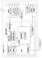
FIG. 1 is a diagram illustrating a configuration of an
図1に示すように、画像表示システム120は、車両の周辺の領域を示す画像を生成する画像生成装置100と、車両に乗車中のユーザに対して各種情報を表示するナビゲーション装置20とを主に備えている。画像生成装置100で生成された画像は、ナビゲーション装置20において表示される。
As shown in FIG. 1, an
ナビゲーション装置20の主たる機能は、目的地までのルートを案内するものである。ナビゲーション装置20は、タッチパネルを備えた液晶などのディスプレイ21と、ユーザが操作を行うハードスイッチなどの操作部22と、装置全体を制御する制御部23とを備えている。ディスプレイ21の画面がユーザから視認可能なように、ナビゲーション装置20は車両のインストルメントパネルなどに設置される。
The main function of the
ユーザの操作は、操作部22とディスプレイ21のタッチパネルとによって受け付けられる。制御部23は、CPU、RAM及びROMなどを備えたコンピュータであり、所定のプログラムに従ってCPUが演算処理を行うことでルートを案内する機能を含む各種の機能が実現される。ナビゲーション装置20は、画像生成装置100と電気的に接続され、画像生成装置100との間で各種の信号の送受信や、画像生成装置100で生成された画像の受信が可能である。
User operations are accepted by the operation unit 22 and the touch panel of the
ディスプレイ21は、通常は、ナビゲーション装置20単体の機能によって、ルート案内用の画像を表示する。一方で、画像表示システム120の動作モードを変更した場合は、ディスプレイ21は、画像生成装置100で生成された車両の周辺の様子を示す画像を表示する。したがって、ナビゲーション装置20は、画像生成装置100で生成された画像を表示するための表示装置としても機能する。
The
画像生成装置100は、画像を取得する撮影部5と、その画像を処理する本体部10とを備えている。本体部10は、撮影部5が取得した撮影画像に基づいて、ディスプレイ21に表示するための表示画像を生成する。
The
撮影部5は、車両の周辺を撮影して撮影画像を取得する。撮影部5は、フロントカメラ51、バックカメラ52、左サイドカメラ53、及び、右サイドカメラ54の4つの車載カメラを備えている。車載カメラ51〜54のそれぞれは、レンズと撮像素子とを備えており電子的に画像を取得する。車載カメラ51〜54で取得された撮影画像は、本体部10に入力される。
The photographing
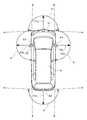
これらの車載カメラ51〜54は、車両の異なる位置にそれぞれ配置され、車両の周辺の互いに異なる方向を撮影する。図2は、車載カメラ51〜54が車両9に配置される位置を示す図である。
These in-
図2に示すように、フロントカメラ51は、車両9の前端の左右中央の近傍に設けられ、その光軸51aは車両9の前方(直進方向)に向けられている。バックカメラ52は、車両9の後端の左右中央の近傍に設けられ、その光軸52aは車両9の後方(直進方向の逆方向)に向けられている。左サイドカメラ53は車両9の左側のサイドミラー93に設けられ、その光軸53aは車両9の左側方(直進方向の直交方向)に向けられている。また、右サイドカメラ54は車両9の右側のサイドミラー93に設けられ、その光軸54aは車両9の右側方(直進方向の直交方向)に向けられている。
As shown in FIG. 2, the
これらの車載カメラ51〜54のレンズには魚眼レンズなどが採用され、各車載カメラ51〜54は180度以上の画角θを有している。このため、4つの車載カメラ51〜54を利用することで、車両9の全周囲を撮影することが可能となっている。
A fish-eye lens or the like is employed for the lenses of these in-
図1に戻り、画像生成装置100は、ユーザが操作可能な切替スイッチ44を備えている。ユーザが切替スイッチ44を操作した場合は、その操作を示す信号が本体部10に入力される。切替スイッチ44は、ユーザが操作しやすいように、本体部10とは別に車室内の適位置に配置される。
Returning to FIG. 1, the
また、画像生成装置100の本体部10は、撮影部5から撮影画像を取得する画像取得部41と、表示画像を生成する画像生成部3と、ナビゲーション装置20と通信するナビ通信部42と、他の装置からの信号を受信する信号受信部43と、画像表示システム120の全体を制御する制御部1と、を主に備えている。
The
画像取得部41は、撮影部5の4つの車載カメラ51〜54のそれぞれから撮影画像を取得する。したがって、画像取得部41は、車両9の前方、後方、左側方及び右側方をそれぞれ示す4つの撮影画像を取得する。
The
画像生成部3は、各種の画像処理を行うハードウェア回路である。画像生成部3は、画像取得部41が取得した撮影画像を処理し、ディスプレイ21に表示するための表示画像を生成する。画像生成部3は、合成画像生成部31及び表示画像生成部32を主な機能として備えている。
The
合成画像生成部31は、4つの車載カメラ51〜54で取得された撮影画像に基づいて、仮想視点からみた車両9の周辺の領域を示す合成画像を生成する。合成画像生成部31が合成画像を生成する手法については後述する。
The composite
表示画像生成部32は、撮影部5で取得された撮影画像と、合成画像生成部31が生成した合成画像とを利用して、ディスプレイ21で表示するための表示画像を生成する。表示画像生成部32は、撮影画像及び合成画像に対して拡大縮小、及び、切り出しなどの画像処理を行い、撮影画像及び合成画像を所定のサイズにする。そして、表示画像生成部32は、この撮影画像及び合成画像を所定の位置に配置することで表示画像を生成する。
The display
ナビ通信部42は、ナビゲーション装置20との間で信号の送受信を行う。ナビ通信部42は、表示画像生成部32が生成した表示画像を、ナビゲーション装置20に出力する。これにより、車両9の周辺を示す表示画像がナビゲーション装置20のディスプレイ21に表示される。また、ナビゲーション装置20の操作部22やディスプレイ21にユーザの操作がなされた場合は、ナビ通信部42がその操作の内容を示す信号を受信して、制御部1に入力する。
The
信号受信部43は、画像表示システム120とは別に車両9に設けられる他の装置からの信号を受信する。信号受信部43は、車両9の変速装置のシフトレバーの位置であるシフトポジションを示す信号をシフトセンサ71から受信して、制御部1に入力する。
The
制御部1は、画像表示システム120の全体を統括的に制御するコンピュータである。制御部1は、CPU、RAM及びROMなどを備えており、所定のプログラムに従ってCPUが演算処理を行うことで各種の制御機能が実現される。ナビゲーション装置20や切替スイッチ44にユーザの操作がなされた場合は、その操作の内容を示す信号が制御部1に入力される。制御部1は、この信号に応答して、ユーザの操作に基づく指示に従って画像表示システム120を動作させる。
The
図中に示す画像制御部11及びシフト判定部12は、プログラムに従った演算処理により実現される制御部1の機能のうちの一部である。
An
画像制御部11は、画像生成部3によって実行される画像処理に係る制御を行う。例えば、画像制御部11は、合成画像の生成に必要な各種パラメータを合成画像生成部31に与える。また、画像制御部11は、画像表示システム120の動作モード、及び、車両の進行方向に応じて、生成すべき表示画像の内容を表示画像生成部32に指示する。
The
シフト判定部12は、車両9のシフトセンサ71からの信号に基づいて、シフトポジションが「P」(駐車),「D」(前進),「N」(中立),「R」(後退)のいずれであるかを判定する。これにより、シフト判定部12は、実質的に、車両9の進行方向が前方あるいは後方のいずれであるかを判定する。
Based on the signal from the
また、本体部10は、電源オフ時においても記憶内容を維持可能な不揮発性メモリ40をさらに備えている。不揮発性メモリ40は、例えば、ハードディスクやフラッシュメモリなどである。不揮発性メモリ40には、視点データ4a及び投影面データ4bが記憶されている。これらのデータ4a,4bは、合成画像を生成する際に利用される。
The
<1−2.画像合成処理>
次に、画像生成部3の合成画像生成部31が、仮想視点からみた車両9の周囲の領域を示す合成画像を生成する手法について説明する。図3は、合成画像を生成する手法を説明するための図である。
<1-2. Image composition processing>
Next, a method in which the composite
撮影部5のフロントカメラ51、バックカメラ52、左サイドカメラ53、及び、右サイドカメラ54のそれぞれで撮影が行われると、車両9の前方、後方、左側方及び右側方をそれぞれ示す4つの撮影画像P1〜P4が取得される。これら4つの撮影画像P1〜P4には、車両9の全周囲のデータが含まれている。
When shooting is performed with each of the
このように取得された4つの撮影画像P1〜P4のデータ(各画素の値)は、仮想の投影面TSに投影される。投影面TSの中心の部分は、車両9が存在する位置として定められている。そして、投影面TSのその他の部分は撮影画像P1〜P4のデータと予め対応付けられており、対応するデータが投影される。
The data (values of each pixel) of the four captured images P1 to P4 acquired in this way are projected on the virtual projection plane TS. A central portion of the projection surface TS is determined as a position where the
投影面TSにおいて車両9の前方の領域は、フロントカメラ51で得られた撮影画像P1のデータが投影される。また、投影面TSにおいて車両9の後方の領域は、バックカメラ52で得られた撮影画像P2のデータが投影される。また、投影面TSにおいて車両9の左側方の領域は左サイドカメラ53で得られた撮影画像P3のデータが投影され、投影面TSにおいて車両9の右側方の領域は右サイドカメラ54で得られた撮影画像P4のデータが投影される。
In the area in front of the
また、投影面TSの車両9が存在する位置に対して、車両9の像が重畳される。この車両9の像は、予めビットマップ等で準備され、不揮発性メモリ40に記憶されている。このようにして、投影面TSの各部分のデータが決定される。
Further, the image of the
このように投影面TSの各部分のデータが決定されると、仮想視点VPが設定される。具体的には、車両9及び車両9の周辺を俯瞰するように仮想視点VPが設定される。そして、投影面TSのうち、設定された仮想視点VPからみて所定の角度に含まれる領域が切り出される。このようにして切り出して得られる画像が、仮想視点VPからみた車両9の周囲の領域を示す合成画像CPとなる。
Thus, when the data of each part of the projection surface TS is determined, the virtual viewpoint VP is set. Specifically, the virtual viewpoint VP is set so as to overlook the
図3においては、投影面TSは平面に描かれているが、合成画像生成部31は、合成画像の生成に用いる投影面TSの形状を平面以外の形状に変更することが可能である。例えば、合成画像生成部31は、投影面TSを、図4に示すような略半球状(お椀形状)の立体曲面とすることもできる。また、合成画像生成部31は、仮想視点VPの位置を任意に変更することが可能である。仮想視点VPの位置を変更することで、投影面TSのうち合成画像CPとして切り出される領域も変更される。
In FIG. 3, the projection plane TS is drawn on a plane, but the composite
<1−3.動作モード>
次に、画像表示システム120の動作モードについて説明する。図5は、画像表示システム120の動作モードの遷移を示す図である。
<1-3. Operation mode>
Next, the operation mode of the
画像表示システム120は、ナビモードM1、フロントモードM2、及び、バックモードM3の3つの動作モードを有している。ナビモードM1は、ナビゲーション装置20の機能を有効化する動作モードである。
The
ナビモードM1では、画像生成装置100の機能は利用されず、ナビゲーション装置20単体の機能でディスプレイ21に各種の表示がなされる。図6は、ナビモードM1において表示される表示画像DP0の一例を示す図である。この表示画像DP0には、車両9の位置を示す地図画像NPが含まれている。
In the navigation mode M1, the functions of the
図5に戻り、フロントモードM2、及び、バックモードM3は、画像生成装置100の機能を利用して、車両9の周辺の領域を示す表示画像をディスプレイ21に表示する動作モードである。これらの動作モードにおいては、ユーザは、車両9の周辺の状況をほぼリアルタイムで把握することができる。フロントモードM2は、車両9の前方の領域を主に表示する動作モードである。一方、バックモードM3は、車両9の後方の領域を主に表示する動作モードである。
Returning to FIG. 5, the front mode M <b> 2 and the back mode M <b> 3 are operation modes in which a display image showing an area around the
これらの動作モードは、ユーザの操作やシフトポジションに基づいて、制御部1の制御により切り替えられる。例えば、動作モードがナビモードM1の場合において、シフトポジションが「P」「R」以外となっており、かつ、切替スイッチ44が操作されたときには、動作モードはフロントモードM2に切り替えられる(矢印T1)。また、動作モードがフロントモードM2の場合において、切替スイッチ44が操作された場合は、動作モードはナビモードM1に戻る(矢印T2)。
These operation modes are switched by the control of the
また、動作モードがナビモードM1あるいはフロントモードM2の場合において、シフトポジションが「R」となったときは、動作モードがバックモードM3に切り替えられる(矢印T3,T5)。また、動作モードがバックモードM3の場合において、シフトポジションが「R」以外となったときは、動作モードはナビモードM1に戻る(矢印T4)。 Further, when the operation mode is the navigation mode M1 or the front mode M2, when the shift position is “R”, the operation mode is switched to the back mode M3 (arrows T3 and T5). When the operation mode is the back mode M3 and the shift position is other than “R”, the operation mode returns to the navigation mode M1 (arrow T4).
シフトポジションが「R」の場合は、車両9の進行方向が後方となるため、車両9の後方の領域を主に示すバックモードM3に動作モードが移行することになる。一方、シフトポジションが「P」「R」以外の場合は、車両9の進行方向が前方となる。このため、ユーザの必要に応じて、車両9の前方の領域を主に示すフロントモードM2に動作モードが移行することになる。
When the shift position is “R”, the traveling direction of the
画像生成部3は、このような動作モードに応じて生成する表示画像の態様を変更する。これにより、フロントモードM2とバックモードM3とで異なる態様の表示画像がディスプレイ21に表示される。
The
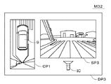
図7は、フロントモードM2の表示画像DP1の一例を示す図である。この表示画像DP1においては、フロント画像SP1と合成画像CP1とアイコンICとが並ぶように含まれている。アイコンICは、フロント画像SP1に示される車両9の周辺の範囲を記号的に示している。
FIG. 7 is a diagram illustrating an example of the display image DP1 in the front mode M2. The display image DP1 includes the front image SP1, the composite image CP1, and the icon IC so as to be arranged. The icon IC symbolically indicates the range around the
フロント画像SP1は、フロントカメラ51で得られた撮影画像を処理したものであり、車両9の前方の領域を示している。フロントモードM2では車両9の進行方向が前方となるため、ユーザは、このフロント画像SP1を視認することによって、車両9の進行方向である前方に存在する物体を把握することができる。フロント画像SP1は、車両9の前方の一部を隠すマスク領域Maを含んでいる。
The front image SP <b> 1 is obtained by processing a captured image obtained by the
また、合成画像CP1は、車両9の周囲の周辺領域A1と、車両9の後方となる後方領域A2とを示している。周辺領域A1は、車両9を中心として車両9の前面、後面、左側面及び右側面のそれぞから所定の距離(例えば、2m)までの範囲の矩形領域である。合成画像CP1は、車両9を俯瞰する仮想視点からみた周辺領域A1を示し、この周辺領域A1の中心となる部分には車両9の像が含まれている。後方領域A2は、この周辺領域A1よりも外側となる車両9の後方の領域である。
The composite image CP <b> 1 shows a peripheral area A <b> 1 around the
そして、合成画像CP1は、周辺領域A1と後方領域A2とを連続的に示している。すなわち、合成画像CP1には、周辺領域A1と後方領域A2とを区切る境界線が設けられておらず、周辺領域A1と後方領域A2とにまたがる被写体の像が連続するように含まれている。 The composite image CP1 continuously indicates the peripheral area A1 and the rear area A2. That is, the composite image CP1 does not include a boundary line that separates the peripheral area A1 and the rear area A2, and includes an image of a subject that extends across the peripheral area A1 and the rear area A2.
ユーザは、このような合成画像CP1を視認することで、車両9の進行方向とは逆方向となる後方に存在する物体を把握することができる。また、合成画像CP1では、周辺領域A1と後方領域A2とが連続的に示されるため、ユーザは、車両9の後方に存在する物体の位置を直感的に把握することができる。
By visually recognizing such a composite image CP1, the user can grasp an object existing behind the
周辺領域A1を示す画像と後方領域A2を示す画像とを別の画像とし、これらを並べて表示することも考えられる。しかしながら、このようにした場合は、周辺領域A1と後方領域A2との位置関係が把握しにくいことから、後方領域A2に物体が存在していたとしても、ユーザはその物体がどこに存在しているかを直感的には把握しにくい。また、後方領域A2から周辺領域A1に近づく物体があった場合は、その物体の像が画像間を移動することになるため、ユーザがその物体の像を見失ってしまう可能性がある。 It is also conceivable that the image showing the peripheral area A1 and the image showing the rear area A2 are different images and displayed side by side. However, in this case, since the positional relationship between the peripheral area A1 and the rear area A2 is difficult to grasp, even if there is an object in the rear area A2, the user is where the object exists. Is difficult to grasp intuitively. Further, when there is an object that approaches the peripheral area A1 from the rear area A2, the image of the object moves between the images, and thus the user may lose sight of the image of the object.
これに対して、本実施の形態の合成画像CP1は、車両9の位置を含む周辺領域A1と後方領域A2とを連続的に示すことから、ユーザは、車両9の後方に存在する物体の車両9に対する相対的な位置を直感的に把握することができる。また、後方領域A2から周辺領域A1に近づく物体があったとしても、その物体の像は合成画像CP1内を移動することになるため、ユーザがその物体の像を見失うこともない。
On the other hand, the composite image CP1 of the present embodiment continuously indicates the peripheral area A1 including the position of the
ユーザは、図7に示す表示画像DP1を視認することで、車両9の前方とともに、車両9の後方の様子を確認することができる。したがって、ユーザは、車両9の進行方向である前方に意識を向けながらも、進行方向とは逆方向の後方に存在する物体も把握することが可能となる。
The user can confirm the state behind the
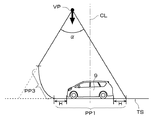
図8は、合成画像生成部31が、図7に示す表示画像DP1に含まれる合成画像CP1を生成する手法を説明するための図である。図8に示すように、合成画像CP1を生成する場合においては、周辺領域A1に相当する部分PP1が平面(水平面)、後方領域A2に相当する部分PP2が曲面となる投影面TSが利用される。部分PP2は、下に凸となる曲面である。部分PP2の車両側の端部は平面の部分PP1と接しており、部分PP2の部分PP1に対する傾きは車両9から離れるほど大きくなっている。
FIG. 8 is a diagram for explaining a method in which the composite
すなわち、投影面TSにおいて、車両9の位置から所定の距離Hまでの範囲の部分PP1は平面となっている。周辺領域A1のデータは、この平面の部分PP1に投影される。一方、投影面TSにおいて、部分PP1よりも車両9の後方となる部分PP2は曲面となっている。後方領域A2のデータは、この曲面の部分PP2に投影される。この投影面TSの形状は、不揮発性メモリ40に記憶された投影面データ4bに含まれている。
That is, on the projection surface TS, the portion PP1 in the range from the position of the
また、仮想視点VPは、車両9の前後中央となる中央線CLよりも後方に設定される。この仮想視点VPの位置は、不揮発性メモリ40に記憶された視点データ4aに含まれている。そして、投影面TSにおいて、このように設定された仮想視点VPからみて所定の角度αに含まれる範囲が合成画像CP1に含まれることになる。
Further, the virtual viewpoint VP is set behind the center line CL that is the front-rear center of the
仮想視点VPが車両9の前後中央よりも後方に設定されることから、図7に示すように、合成画像CP1において車両9の像の中心位置9cは、合成画像CP1の上下中央よりも上側に位置する。これにより、合成画像CP1において、後方領域A2を示す部分を広くすることができ、車両9の進行方向とは逆方向の後方に存在する物体をユーザが把握しやすくすることができる。
Since the virtual viewpoint VP is set behind the front-rear center of the
また仮に、合成画像を生成する場合に、全体が平面となる投影面TSを用いた場合においては、投影面TSに投影される物体の像は車両9の位置から離れるほど拡大する。このため、車両9から近い物体については像の歪みは少ないが、車両9から離間した物体については車両9から離れるほど像の歪が大きくなってしまう。さらに、車両9の周辺の比較的狭い範囲しか、合成画像に含めることができなくなる。
Also, if a composite image is generated and a projection plane TS that is entirely flat is used, the image of the object projected on the projection plane TS increases as the distance from the position of the
これに対して、本実施の形態では、車両9から離間した後方領域A2のデータを投影面TSの曲面の部分PP2に投影するようにしている。このため、車両9から離れた物体の像の歪みを緩和できるとともに、車両9の周辺の比較的広い範囲を合成画像CP1に含めることが可能となる。また、車両9の近傍の周辺領域A1のデータを投影面TSの平面の部分PP1に投影するようにしている。このため、歪みの少ない物体の像を有効に利用できるとともに、車両9の近傍に存在する物体の位置を明瞭に把握することができる。
On the other hand, in the present embodiment, data of the rear region A2 that is separated from the
図9は、バックモードM3の表示画像DP2の一例を示す図である。この表示画像DP2においては、バック画像SP2と合成画像CP2とアイコンICとが並ぶように含まれている。アイコンICは、バック画像SP2に示される車両9の周辺の範囲を記号的に示している。
FIG. 9 is a diagram illustrating an example of the display image DP2 in the back mode M3. In the display image DP2, the back image SP2, the composite image CP2, and the icon IC are included so as to be arranged. The icon IC symbolically indicates the range around the
バック画像SP2は、フロントカメラ51で得られた撮影画像を処理したものであり、車両9の後方の領域を示している。バックモードM3では車両9の進行方向が後方となるため、ユーザは、このバック画像SP2を視認することによって、車両9の進行方向である後方に存在する物体を把握することができる。
The back image SP <b> 2 is obtained by processing a captured image obtained by the
また、合成画像CP2は、車両9の周囲の周辺領域A1と、車両9の前方となる前方領域A3とを示している。合成画像CP2も、車両9を俯瞰する仮想視点からみた周辺領域A1を示し、この周辺領域A1の中心となる部分には車両9の像が含まれている。前方領域A3は、この周辺領域A1よりも外側となる車両9の前方の領域である。
The composite image CP <b> 2 shows a peripheral area A <b> 1 around the
そして、合成画像CP2は、周辺領域A1と前方領域A3とを連続的に示している。すなわち、合成画像CP2には、周辺領域A1と前方領域A3とを区切る境界線が設けられておらず、周辺領域A1と前方領域A3とにまたがる被写体の像が連続するように含まれている。 The composite image CP2 continuously indicates the peripheral area A1 and the front area A3. That is, the composite image CP2 does not have a boundary line that separates the peripheral area A1 and the front area A3, and includes an image of a subject that extends across the peripheral area A1 and the front area A3.
ユーザは、このような合成画像CP2を視認することで、車両9の進行方向とは逆方向となる前方に存在する物体を把握することができる。また、合成画像CP2では、周辺領域A1と前方領域A3とが連続的に示されるため、ユーザは、車両9の前方に存在する物体の車両9に対する相対的な位置を直感的に把握することができる。また、前方領域A3から周辺領域A1に近づく物体があったとしても、その物体の像は合成画像CP2内を移動することになるため、ユーザがその物体の像を見失うこともない。
By visually recognizing such a composite image CP2, the user can grasp an object that exists in the forward direction opposite to the traveling direction of the
ユーザは、図9に示す表示画像DP2を視認することで、車両9の後方とともに、車両9の前方の様子を確認することができる。したがって、ユーザは、車両9の進行方向である後方に意識を向けながらも、進行方向とは逆方向の前方に存在する物体も把握することが可能となる。
The user can confirm the state of the front of the
図10は、合成画像生成部31が、図9に示す表示画像DP2に含まれる合成画像CP2を生成する手法を説明するための図である。図10に示すように、合成画像CP2を生成する場合においては、周辺領域A1に相当する部分PP1が平面(水平面)、前方領域A3に相当する部分PP3が曲面となる投影面TSが利用される。部分PP3は、下に凸となる曲面である。部分PP3の車両側の端部は平面の部分PP1と接しており、部分PP3の部分PP1に対する傾きは車両9から離れるほど大きくなっている。
FIG. 10 is a diagram for describing a method in which the composite
すなわち、投影面TSにおいて、車両9の位置から所定の距離Hまでの範囲の部分PP1は平面となっている。周辺領域A1のデータは、この平面の部分PP1に投影される。一方、投影面TSにおいて、部分PP1よりも車両9の前方となる部分PP3は曲面となっている。前方領域A3のデータは、この曲面の部分PP3に投影される。この投影面TSの形状は、不揮発性メモリ40に記憶された投影面データ4bに含まれている。
That is, on the projection surface TS, the portion PP1 in the range from the position of the
また、仮想視点VPが、車両9の前後中央となる中央線CLよりも前方に設定される。この仮想視点VPの位置は、不揮発性メモリ40に記憶された視点データ4aに含まれている。そして、投影面TSにおいて、このように設定された仮想視点VPからみて所定の角度αに含まれる範囲が合成画像CP2に含まれることになる。
Further, the virtual viewpoint VP is set in front of the center line CL that is the front-rear center of the
仮想視点VPが車両9の前後中央よりも前方に設定されることから、図9に示すように、合成画像CP2において車両9の像の中心位置9cは、合成画像CP1の上下中央よりも下側に位置する。これにより、合成画像CP1において、前方領域A3を示す部分を広くすることができ、車両9の進行方向とは逆方向の前方に存在する物体をユーザが把握しやすくすることができる。
Since the virtual viewpoint VP is set in front of the front-rear center of the
また、車両9から離間した前方領域A3のデータを投影面TSの曲面の部分PP3に投影するため、車両9から離れた物体の像の歪みを緩和できるとともに、車両9の周辺の比較的広い範囲を合成画像CP2に含めることが可能となる。また、この場合も、車両9の近傍の周辺領域A1のデータを投影面TSの平面の部分PP1に投影するようにしているため、歪みの少ない物体の像を有効に利用できるとともに、車両9の近傍に存在する物体の位置を明瞭に把握することができる。
Further, since the data of the front area A3 separated from the
<1−4.処理>
次に、画像表示システム120の処理の流れについて説明する。図11は、画像表示システム120が、車両9の周辺の領域を示す表示画像を表示する場合(フロントモードM2、または、バックモードM3)における処理の流れを示す図である。フロントモードM2、または、バックモードM3においては、図11に示す処理が所定の周期(例えば、1/30秒)で繰り返し実行される。
<1-4. Processing>
Next, a processing flow of the
まず、シフト判定部12が、シフトセンサ71からの信号に基づいて、現時点におけるシフトポジションを判定する。これにより、シフト判定部12は、実質的に現時点の車両9の進行方向を判定する(ステップS11)。以降、車両9の進行方向に応じて処理の内容が異なる。
First, the
車両9の進行方向が前方の場合(すなわち、フロントモードM2の場合)(ステップS12にてYes)は、まず、画像取得部41が4つの車載カメラ51〜54から4つの撮影画像を取得する(ステップS13)。
When the traveling direction of the
次に、合成画像生成部31が、これらの撮影画像を用いて、図8で説明した手法により、周辺領域A1と後方領域A2とを連続的に示す合成画像CP1を生成する(ステップS14)。そして、表示画像生成部32が、この合成画像CP1と、車両9の前方の領域を示すフロント画像SP1と含む表示画像DP1(図7参照。)を生成する(ステップS15)。
Next, the composite
このようにして生成された表示画像DP1は、ナビ通信部42からナビゲーション装置20に出力される。これにより、表示画像DP1が、ナビゲーション装置20のディスプレイ21に表示される(ステップS19)。
The display image DP1 generated in this way is output from the
一方、車両9の進行方向が後方の場合(すなわち、バックモードM3の場合)(ステップS12にてNo)は、まず、画像取得部41が4つの車載カメラ51〜54から4つの撮影画像を取得する(ステップS16)。
On the other hand, when the traveling direction of the
次に、合成画像生成部31が、これらの撮影画像を用いて、図10で説明した手法により、周辺領域A1と前方領域A3とを連続的に示す合成画像CP2を生成する(ステップS17)。そして、表示画像生成部32が、この合成画像CP2と、車両9の後方の領域を示すバック画像SP2と含む表示画像DP2(図9参照。)を生成する(ステップS18)。
Next, the composite
このようにして生成された表示画像DP2は、ナビ通信部42からナビゲーション装置20に出力される。これにより、表示画像DP2が、ナビゲーション装置20のディスプレイ21に表示される(ステップS19)。
The display image DP2 generated in this way is output from the
以上説明したように、第1の実施の形態の画像表示システム120では、シフト判定部12が車両9の進行方向を判定する。そして、合成画像生成部31が、車両9を俯瞰する仮想視点からみた車両9の周囲の周辺領域A1と、車両9の周辺領域A1より外側の進行方向とは逆方向の領域(後方領域A2または前方領域A3)とを連続的に示す合成画像を生成する。ディスプレイ21は、この合成画像を含む表示画像を表示する。表示画像が車両9の進行方向とは逆方向の領域を示す合成画像を含むため、ユーザは表示画像を視認することで車両9の進行方向とは逆方向に存在する物体を把握することができる。また、周辺領域A1と車両9の進行方向とは逆方向の領域とが連続的に示されるため、車両9の進行方向とは逆方向に存在する物体の位置をユーザが直感的に把握することができる。
As described above, in the
<2.第2の実施の形態>
次に、第2の実施の形態について説明する。第2の実施の形態の画像表示システムの動作及び処理は、第1の実施の形態とほぼ同様であるため、以下、第1の実施の形態との相違点を中心に説明する。第1の実施の形態では、車両9の進行方向が後方の場合(すなわち、バックモードM3の場合)においては、バック画像を含む表示画像が表示され、フロント画像を含む表示画像を表示することはなかった。
<2. Second Embodiment>
Next, a second embodiment will be described. Since the operation and processing of the image display system of the second embodiment are substantially the same as those of the first embodiment, the following description will be focused on differences from the first embodiment. In the first embodiment, when the traveling direction of the
これに対して、第2の実施の形態では、車両9の進行方向が後方の場合において、バック画像を含む表示画像と、フロント画像を含む表示画像とを、ユーザの操作によって切り替えて表示できるようになっている。より具体的には、車両9の進行方向が後方の場合においては、画像生成部3が、バック画像を含む表示画像と、フロント画像を含む表示画像との一方をユーザの操作に応じて選択的に生成する。そして、生成された表示画像がディスプレイ21に表示される。これにより、第2の実施の形態では、車両9の進行方向が後方の場合においても、ユーザは必要に応じて、車両9の前方の領域を表示画像によって確認することが可能となっている。
On the other hand, in the second embodiment, when the traveling direction of the
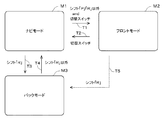
図12は、第2の実施の形態の画像表示システム120の動作モードの遷移を示す図である。第2の実施の形態においても、画像表示システム120の動作モードには、ナビモードM1、フロントモードM2、及び、バックモードM3があり、これらの動作モードは第1の実施の形態と同様に変更される(矢印T1〜T5)。フロントモードM2においては、第1の実施の形態と同一の態様の表示画像DP1(図7参照。)がディスプレイ21に表示される。
FIG. 12 is a diagram illustrating transition of operation modes of the
ただし、第2の実施の形態においては、バックモードM3は、2つのサブモードを含んでいる。一方のサブモードは車両9の後方の領域を主に表示する後方表示モードM31であり、他方のサブモードは車両9の前方の領域を主に表示する前方表示モードM32である。動作モードがバックモードM3に切り替えられた直後は、サブモードは後方表示モードM31となる。その後、ユーザが切替スイッチ44を操作するごとに、サブモードは後方表示モードM31と前方表示モードM32との間で切り替えられる(矢印T6)。すなわち、ユーザが切替スイッチ44を操作するごとに、画像生成部3が異なる態様の表示画像を生成し、その表示画像がディスプレイ21に表示されることになる。
However, in the second embodiment, the back mode M3 includes two submodes. One sub-mode is a rear display mode M31 that mainly displays a rear area of the
後方表示モードM31においては、車両9の後方を示すバック画像を含む表示画像が生成されて、ディスプレイ21に表示される。一方、前方表示モードM32においては、車両9の前方を示すフロント画像を含む表示画像が生成されて、ディスプレイ21に表示される。後方表示モードM31の表示画像の態様は、第1の実施の形態のバックモードM3の表示画像DP2(図9参照。)と同一である。これに対して、前方表示モードM32の表示画像の態様は、フロントモードM2の表示画像DP1(図7参照。)とは異なっている。
In the rear display mode M <b> 31, a display image including a back image indicating the rear of the
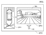
図13は、前方表示モードM32の表示画像DP3の一例を示す図である。この表示画像DP3においては、フロント画像SP3と合成画像CP1とアイコンICとが並ぶように含まれている。フロント画像SP3は、フロントカメラ51で得られた撮影画像を処理したものであり、車両9の前方の領域を示している。アイコンICは、フロント画像SP3に示される車両9の周辺の範囲を記号的に示している。
FIG. 13 is a diagram illustrating an example of the display image DP3 in the forward display mode M32. The display image DP3 includes the front image SP3, the composite image CP1, and the icon IC so as to be arranged. The front image SP3 is obtained by processing a captured image obtained by the
図7と図13とを比較してわかるように、フロントモードM2の表示画像DP1が含むフロント画像SP1と、前方表示モードM32の表示画像DP3が含むフロント画像SP3とは、その態様が異なっている。前述のように、フロントモードM2のフロント画像SP1(図7参照。)は、車両9の前方の一部を隠す非透過のマスク領域Maを含んでいる。これに対して、前方表示モードM32のフロント画像SP3(図13参照。)は、このようなマスク領域を含んでいない。このように、フロントモードM2の表示画像DP1と、前方表示モードM32の表示画像DP3とは、車両9の前方を異なる態様で示すことになる。
As can be seen by comparing FIG. 7 and FIG. 13, the front image SP1 included in the display image DP1 in the front mode M2 and the front image SP3 included in the display image DP3 in the front display mode M32 have different aspects. . As described above, the front image SP1 (see FIG. 7) in the front mode M2 includes the non-transparent mask area Ma that hides a part of the front of the
仮に、フロントモードM2の表示画像と前方表示モードM32の表示画像とを同一の態様としたとすると、ユーザは、前方表示モードM32の表示画像を視認した場合に、画像表示システム120の現時点の動作モードがフロントモードM2であると誤解する可能性がある。換言すれば、ユーザは、前方表示モードM32の表示画像を視認した場合に、現時点の車両9の進行方向が前方であると誤解する可能性がある。これに対して、本実施の形態では、フロントモードM2の表示画像DP1と前方表示モードM32の表示画像DP3とが異なる態様であるため、ユーザが車両9の進行方向を誤解することを防止できる。
Assuming that the display image in the front mode M2 and the display image in the front display mode M32 are in the same mode, when the user visually recognizes the display image in the front display mode M32, the current operation of the
フロントモードM2では車両9の進行方向が前方となるため、ユーザは、車両9の前方の領域のうち直接的に確認可能な領域については、自分の目で確認することが望ましい。このため、フロントモードM2のフロント画像SP1は、車両9の前方の領域のうち直接的に確認可能な一部の領域を隠すためのマスク領域Maを含み、直接的に確認しにくい領域(死角となる領域)を主に示すようになっている。
Since the traveling direction of the
これに対して、前方表示モードM32は、車両9の進行方向が後方の場合における車両9の前方の領域の確認が目的であるため、車両9の前方の広い範囲を確認できるようになっていることが望ましい。このため、前方表示モードM32の表示画像DP3は、マスク領域を含まず、車両9の前方の広い範囲を示すことができるようになっている。
On the other hand, the front display mode M32 is intended to confirm the area in front of the
なお、図13の例では、前方表示モードM32のフロント画像SP3はマスク領域を含んでいないが、フロントモードM2の表示画像DP1と前方表示モードM32の表示画像DP3とが明確に区別できれば、前方表示モードM32のフロント画像SP3がマスク領域を含んでいてもよい。 In the example of FIG. 13, the front image SP3 in the front display mode M32 does not include a mask area. However, if the display image DP1 in the front mode M2 and the display image DP3 in the front display mode M32 can be clearly distinguished, the front display The front image SP3 in mode M32 may include a mask area.
例えば、図14に示すように、前方表示モードM32のフロント画像SP3が、透過性のマスク領域Mbを含むようにしてもよい。この図14に示す表示画像DP3では、マスク領域Mbの部分であってもユーザは車両9の前方の領域を確認できるため、車両9の前方の広い範囲を示すことができる。
For example, as shown in FIG. 14, the front image SP3 in the front display mode M32 may include a transmissive mask region Mb. In the display image DP3 shown in FIG. 14, since the user can confirm the area in front of the
また、図15に示すように、前方表示モードM32のフロント画像SP3が、フロントモードM2のマスク領域Maとは異なる形状のマスク領域Mcを含むようにしてもよい。このように、フロントモードM2の表示画像DP1と前方表示モードM32の表示画像DP3とで、マスク領域の形状を明確に異ならせることで、ユーザは、現在表示されている表示画像がいずれの動作モードの表示画像であるかを明確に区別することができる。これにより、ユーザは、現時点の車両9の進行方向がいずれであるかを直感的に把握することができる。
Further, as shown in FIG. 15, the front image SP3 in the front display mode M32 may include a mask area Mc having a shape different from that of the mask area Ma in the front mode M2. In this way, by clearly changing the shape of the mask area between the display image DP1 in the front mode M2 and the display image DP3 in the front display mode M32, the user can select which operation mode the currently displayed display image is. Can be clearly distinguished. Thereby, the user can grasp intuitively which traveling direction of the
以上のように、第2の実施の形態の画像表示システム120では、車両9の進行方向が前方の場合に表示される表示画像DP1と、車両9の進行方向が後方の場合に表示される表示画像DP3とが、車両9の前方を異なる態様で示す。このため、ユーザが車両9の進行方向を誤解することを防止できる。
As described above, in the
<3.第3の実施の形態>
次に、第3の実施の形態について説明する。第3の実施の形態の画像表示システムの動作及び処理は、第1の実施の形態とほぼ同様であるため、以下、第1の実施の形態との相違点を中心に説明する。
<3. Third Embodiment>
Next, a third embodiment will be described. Since the operation and processing of the image display system of the third embodiment are substantially the same as those of the first embodiment, the following description will be focused on differences from the first embodiment.
従来の画像表示システムでは、車両のサイドミラーが格納された場合について考慮されていなかった。車両のサイドミラーは、車両の駐車時以外は、車両が他の車両等とすれ違う場合や車両が比較的狭い道路を走行する場合など、車両の側面が他の物体と近接する場合に格納されることが多い。したがって、車両が走行可能な状態でサイドミラーが格納された場合は、車両9の側面が他の物体と近接する場合であると想定される。このため、第3の実施の形態の画像表示システム120では、サイドミラー93が格納された場合は、車両9の側面が他の物体と近接した状態で走行する場合に有用な表示画像を表示するようにしている。
In the conventional image display system, the case where the side mirror of the vehicle is stored is not considered. The side mirror of the vehicle is stored when the side of the vehicle is close to other objects, such as when the vehicle passes another vehicle or when the vehicle travels on a relatively narrow road, except when the vehicle is parked. There are many cases. Therefore, when the side mirror is stored in a state where the vehicle can travel, it is assumed that the side surface of the
図16は、第3の実施の形態の画像表示システム120の構成を示す図である。第3の実施の形態では、制御部1が、プログラムに従った演算処理により実現される機能として、画像制御部11及びシフト判定部12に加えて、ミラー検出部13をさらに備えている。第3の実施の形態の画像表示システム120のその他の構成は、図1に示す第1の実施の形態の画像表示システム120の構成と同様である。ミラー検出部13は、車両9のサイドミラー93を駆動させるミラー駆動部72からの信号に基づいて、サイドミラー93の状態(格納/展開)を検出する。ミラー駆動部72は、ユーザの指示に従って、サイドミラー93を格納、あるいは、展開させる。
FIG. 16 is a diagram illustrating a configuration of an
図17は、第3の実施の形態の画像表示システム120の動作モードの遷移を示す図である。第3の実施の形態の画像表示システム120は、動作モードとして、ナビモードM1、フロントモードM2及びバックモードM3の他に、すれ違いモードM4を有している。第3の実施の形態においても、ナビモードM1、フロントモードM2及びバックモードM3については、第1の実施の形態(図5参照。)と同様に変更される。
FIG. 17 is a diagram illustrating transition of operation modes of the
第3の実施の形態では、動作モードがナビモードM1の場合において、サイドミラー93が格納されたときは、動作モードがすれ違いモードM4に切り替えられる(矢印T7)。また、動作モードがすれ違いモードM4の場合において、サイドミラー93が展開されたときは、動作モードはナビモードM1に戻る(矢印T8)。なお、動作モードがフロントモードM2またはバックモードM3の場合に、サイドミラー93が格納されたときに、動作モードがすれ違いモードM4に切り替えられてもよい。
In the third embodiment, when the operation mode is the navigation mode M1 and the
すれ違いモードM4は、車両9の側面が他の物体と近接した状態で走行する場合に有用な表示画像をディスプレイ21に表示する動作モードである。車両9の側面が他の物体と近接する場合には、ユーザは、車両9の側面と他の物体とのクリアランスを確認する必要がある。しかしながら、このような車両9の側方の領域、特に運転席から逆側の領域については、ユーザが直接的に確認することは難しい。このため、すれ違いモードM4では、このような車両9の側方の領域を示す表示画像が表示される。
The passing mode M4 is an operation mode in which a display image that is useful when the
すれ違いモードM4において、画像生成部3の表示画像生成部32は、左右のサイドカメラ53,54の撮影画像に基づいて、車両9の側方、かつ、進行方向を示す表示画像を生成する。そして、生成された表示画像がディスプレイ21に表示される。したがって、すれ違いモードM4では、車両9の進行方向に応じて異なる態様の表示画像が表示される。
In the passing mode M4, the display
図18は、すれ違いモードM4において、車両9の進行方向が前方の場合の表示画像DP4の一例を示す図である。この表示画像DP4においては、2つのサイド画像FP1,FP2とアイコンICとが並ぶように含まれている。アイコンICは、2つのサイド画像FP1,FP2に示される車両9の周辺の範囲を記号的に示している。
FIG. 18 is a diagram illustrating an example of the display image DP4 when the traveling direction of the
左サイド画像FP1は、車両9の左側方、かつ、車両9の進行方向となる前方の領域を示している。より具体的には、左サイド画像FP1は、車両9の左側のサイドミラー93よりも前方の領域を示している。また、左サイド画像FP1には、車両9の左側の前タイヤ近傍の車体の像が含まれている。
The left side image FP <b> 1 shows a region on the left side of the
一方、右サイド画像FP2は、車両9の右側方、かつ、車両9の進行方向となる前方の領域を示している。より具体的には、右サイド画像FP2は、車両9の右側のサイドミラー93よりも前方の領域を示している。また、右サイド画像FP2には、車両9の右側の前タイヤ近傍の車体の像が含まれている。
On the other hand, the right side image FP2 shows a region on the right side of the
図19は、表示画像DP4に含まれるサイド画像FP1,FP2を生成する手法を説明する図である。左サイド画像FP1は、左サイドカメラ53で得られた撮影画像P3における、車両9の側(図中右側)、かつ、サイドミラー93の前方に対応する領域FA1を切り出すことで生成される。一方、右サイド画像FP2は、右サイドカメラ54で得られた撮影画像P4中における、車両9の側(図中左側)、かつ、サイドミラー93の前方に対応する領域FA2を切り出すことで生成される。
FIG. 19 is a diagram illustrating a method for generating the side images FP1 and FP2 included in the display image DP4. The left side image FP1 is generated by cutting out a region FA1 corresponding to the
ユーザは、図18に示す表示画像DP4を視認することによって、車両9の側方、かつ、車両9の進行方向となる前方に存在する物体を把握することができる。また、表示画像DP4のサイド画像FP1,FP2は、車両9の車体の一部の像を含むため、ユーザは、車両9の車体と他の物体とのクリアランスを把握できる。したがって、ユーザは、車両9の側面が他の物体と近接した状態で車両9を前進させる場合において、車両9と他の物体との接触を容易に回避することができる。
By visually recognizing the display image DP4 shown in FIG. 18, the user can grasp an object that exists on the side of the
図20は、すれ違いモードM4において、車両9の進行方向が後方の場合の表示画像DP5の一例を示す図である。この表示画像DP5においては、2つのサイド画像RP1,RP2とアイコンICとが並ぶように含まれている。アイコンICは、2つのサイド画像RP1,RP2に示される車両9の周辺の範囲を記号的に示している。
FIG. 20 is a diagram illustrating an example of the display image DP5 when the traveling direction of the
左サイド画像RP1は、車両9の左側方、かつ、車両9の進行方向となる後方の領域を示している。より具体的には、左サイド画像RP1は、車両9の左側のサイドミラー93よりも後方の領域を示している。また、左サイド画像FP1には、車両9の左側の後タイヤ近傍の車体の像が含まれている。
The left side image RP <b> 1 shows a region on the left side of the
一方、右サイド画像RP2は、車両9の右側方、かつ、車両9の進行方向となる後方の領域を示している。より具体的には、右サイド画像RP2は、車両9の右側のサイドミラー93よりも後方の領域を示している。また、右サイド画像RP2には、車両9の右側の後タイヤ近傍の車体の像が含まれている。
On the other hand, the right side image RP <b> 2 shows a region on the right side of the
図21は、表示画像DP5に含まれるサイド画像RP1,RP2を生成する手法を説明する図である。左サイド画像RP1は、左サイドカメラ53で得られた撮影画像P3における、車両9の側(図中右側)、かつ、サイドミラー93の後方に対応する領域RA1を切り出すことで生成される。一方、右サイド画像RP2は、右サイドカメラ54で得られた撮影画像P4中における、車両9の側(図中左側)、かつ、サイドミラー93の後方に対応する領域RA2を切り出すことで生成される。
FIG. 21 is a diagram illustrating a method for generating the side images RP1 and RP2 included in the display image DP5. The left side image RP1 is generated by cutting out a region RA1 corresponding to the
ユーザは、図20に示す表示画像DP5を視認することによって、車両9の側方、かつ、車両9の進行方向となる後方に存在する物体を把握することができる。また、表示画像DP5のサイド画像RP1,RP2は、車両9の車体の一部の像を含むため、ユーザは、車両9の車体と他の物体とのクリアランスを把握できる。したがって、ユーザは、車両9の側面が他の物体と近接した状態で車両9を後退させる場合において、車両9と他の物体との接触を容易に回避することができる。
By visually recognizing the display image DP5 shown in FIG. 20, the user can grasp an object that exists on the side of the
図22は、すれ違いモードM4における画像表示システム120の処理の流れを示す図である。この処理は、サイドミラー93が格納されて動作モードがすれ違いモードM4に移行した以降、所定の周期(例えば、1/30秒)で繰り返し実行される。
FIG. 22 is a diagram illustrating a process flow of the
まず、ミラー検出部13が、ミラー駆動部72からの信号に基づいて、サイドミラー93の状態(格納/展開)を検出する。サイドミラー93が展開されている場合は(ステップS21にてNo)、すれ違いモードM4の処理は終了する。
First, the
一方、サイドミラー93が格納されている場合は(ステップS21にてYes)、続いて、シフト判定部12が、シフトセンサ71からの信号に基づいて、現時点におけるシフトポジションを判定する。これにより、シフト判定部12は、実質的に現時点の車両9の進行方向を判定する(ステップS22)。
On the other hand, when the
車両9の進行方向が前方の場合(シフトポジションが「R」以外の場合)(ステップS23にてYes)は、まず、画像取得部41が左右のサイドカメラ53,54からそれぞれ撮影画像を取得する(ステップS24)。
When the traveling direction of the
次に、表示画像生成部32が、これらの撮影画像を用いて図19で示した手法により、車両9の側方、かつ、前方を示す表示画像DP4を生成する(ステップS25)。生成された表示画像DP4は、ナビ通信部42からナビゲーション装置20に出力される。これにより、表示画像DP4が、ナビゲーション装置20のディスプレイ21に表示される(ステップS28)。
Next, the display
一方、車両9の進行方向が後方の場合(シフトポジションが「R」の場合)(ステップS23にてNo)は、まず、画像取得部41が左右のサイドカメラ53,54からそれぞれ撮影画像を取得する(ステップS26)。
On the other hand, when the traveling direction of the
次に、表示画像生成部32が、これらの撮影画像を用いて図21で示した手法により、車両9の側方、かつ、後方を示す表示画像DP5を生成する(ステップS27)。生成された表示画像DP5は、ナビ通信部42からナビゲーション装置20に出力される。これにより、表示画像DP5が、ナビゲーション装置20のディスプレイ21に表示される(ステップS28)。
Next, the display
以上のように、第3の実施の形態の画像表示システム120では、サイドミラー93が格納された場合に、車両9の側方、かつ、進行方向を示す表示画像が生成され、ディスプレイ21に表示される。したがって、ユーザは、車両9の側面が他の物体と近接する場合において、確認しにくい車両9の側方の様子を容易に把握することができる。
As described above, in the
<4.変形例>
以上、本発明の実施の形態について説明してきたが、この発明は上記実施の形態に限定されるものではなく様々な変形が可能である。以下では、このような変形例について説明する。上記実施の形態及び以下で説明する形態を含む全ての形態は、適宜に組み合わせ可能である。
<4. Modification>
Although the embodiments of the present invention have been described above, the present invention is not limited to the above-described embodiments, and various modifications are possible. Below, such a modification is demonstrated. All the forms including the above-described embodiment and the form described below can be appropriately combined.
第1の実施の形態では、フロントモードM2の合成画像CP1に示される周辺領域A1と、バックモードM3の合成画像CP2に示される周辺領域A1とは同一の領域であったが、同一の領域でなくてもよい。 In the first embodiment, the peripheral area A1 shown in the composite image CP1 in the front mode M2 and the peripheral area A1 shown in the composite image CP2 in the back mode M3 are the same area. It does not have to be.
第3の実施の形態では、表示画像において車両9の左側方と右側方との双方が示されていたが、車両9の左側方と右側方とのいずれか一方を示すようにしてもよい。このような場合、表示画像は、ユーザにとって確認することが難しい運転席から逆側の側方を示すことが望ましい。
In the third embodiment, both the left side and the right side of the
また、上記実施の形態では、画像生成装置100の本体部10とナビゲーション装置20とは別の装置であるとして説明したが、本体部10とナビゲーション装置20とが同一の筐体内に配置されて一体型の装置として構成されてもよい。
In the above embodiment, the
また、上記実施の形態では、画像生成装置100で生成された画像を表示する表示装置はナビゲーション装置20であるとして説明したが、ナビゲーション機能等の特殊な機能を有していない一般的な表示装置であってもよい。
In the above embodiment, the display device that displays the image generated by the
また、上記実施の形態において、画像生成装置100の制御部1によって実現されると説明した機能の一部は、ナビゲーション装置20の制御部23によって実現されてもよい。
In the above embodiment, some of the functions described as being realized by the
また、シフトセンサ71やミラー駆動部72からの信号は、ナビゲーション装置20が受信するようになっていてもよい。この場合は、ナビ通信部42を経由して、画像生成装置100の制御部1に当該信号を入力すればよい。
Further, the
また、上記実施の形態では、プログラムに従ったCPUの演算処理によってソフトウェア的に各種の機能が実現されると説明したが、これら機能のうちの一部は電気的なハードウェア回路により実現されてもよい。また逆に、ハードウェア回路によって実現されるとした機能のうちの一部は、ソフトウェア的に実現されてもよい。 Further, in the above-described embodiment, it has been described that various functions are realized in software by the arithmetic processing of the CPU according to the program. However, some of these functions are realized by an electrical hardware circuit. Also good. Conversely, some of the functions realized by the hardware circuit may be realized by software.
◎なお、上述した具体的実施の形態には以下の構成を有する発明が含まれている。 The specific embodiments described above include inventions having the following configurations.
(1)車両において用いられ、前記車両の周辺を示す画像を生成する画像生成装置であって、前記車両の側方を撮影するサイドカメラの撮影画像を取得する取得手段と、前記車両の進行方向を判定する判定手段と、前記車両のサイドミラーの状態を検出する検出手段と、前記サイドミラーが格納された場合は、前記サイドカメラの撮影画像に基づいて前記車両の側方、かつ、前記進行方向を示す表示画像を生成する生成手段と、前記表示画像を表示装置に出力して、前記表示装置に表示させる出力手段と、を備えることを特徴とする画像生成装置。 (1) An image generation apparatus that is used in a vehicle and generates an image showing the periphery of the vehicle, the acquisition unit acquiring a captured image of a side camera that captures a side of the vehicle, and the traveling direction of the vehicle Determining means for determining the state of the side mirror of the vehicle, and when the side mirror is stored, the side of the vehicle based on the captured image of the side camera and the progress An image generation apparatus comprising: a generation unit that generates a display image indicating a direction; and an output unit that outputs the display image to a display device and causes the display device to display the display image.
これによれば、サイドミラーが格納された場合において、車両の側方、かつ、進行方向を示す表示画像が表示される。このため、車両の側面が他の物体と近接する場合において、ユーザは確認しにくい車両の側方の様子を把握することができる。 According to this, when the side mirror is stored, a display image indicating the side of the vehicle and the traveling direction is displayed. For this reason, when the side surface of the vehicle is close to another object, the user can grasp the side of the vehicle that is difficult to confirm.
(2)上記(1)に記載の画像生成装置において、前記表示画像は、前記車両の車体の一部の像を含むことを特徴とする画像生成装置。 (2) The image generation apparatus according to (1), wherein the display image includes an image of a part of a vehicle body of the vehicle.
これによれば、表示画像は車両の車体の一部の像を含むため、ユーザは、車両の車体と他の物体とのクリアランスを把握することができる。 According to this, since the display image includes a partial image of the vehicle body, the user can grasp the clearance between the vehicle body and other objects.
(3)車両において用いられ、前記車両の周辺を示す画像を生成する画像生成方法であって、(a)前記車両の側方を撮影するサイドカメラの撮影画像を取得する工程と、(b)前記車両の進行方向を判定する工程と、(c)前記車両のサイドミラーの状態を検出する工程と、(d)前記サイドミラーが格納された場合は、前記サイドカメラの撮影画像に基づいて前記車両の側方、かつ、前記進行方向を示す表示画像を生成する工程と、(e)前記表示画像を表示する工程と、を備えることを特徴とする画像生成方法。 (3) An image generation method used in a vehicle to generate an image showing the periphery of the vehicle, wherein (a) a captured image of a side camera that captures a side of the vehicle is obtained; (b) Determining a traveling direction of the vehicle; (c) detecting a state of a side mirror of the vehicle; and (d) when the side mirror is stored, based on a captured image of the side camera. An image generation method comprising: a step of generating a display image indicating a side direction of the vehicle and the traveling direction; and (e) a step of displaying the display image.
これによれば、サイドミラーが格納された場合において、車両の側方、かつ、進行方向を示す表示画像が表示される。このため、車両の側面が他の物体と近接する場合において、ユーザは確認しにくい車両の側方の様子を把握することができる。 According to this, when the side mirror is stored, a display image indicating the side of the vehicle and the traveling direction is displayed. For this reason, when the side surface of the vehicle is close to another object, the user can grasp the side of the vehicle that is difficult to confirm.
3 画像生成部
5 撮影部
9 車両
12 シフト判定部
13 ミラー検出部
20 ナビゲーション装置
21 ディスプレイ
42 ナビ通信部
100 画像生成装置
TS 投影面
VP 仮想視点
DESCRIPTION OF
Claims (13)
前記車両の周辺の互いに異なる方向を撮影する複数のカメラの撮影画像を取得する取得手段と、
前記車両の進行方向を判定する判定手段と、
前記撮影画像に基づいて、前記車両を俯瞰する仮想視点からみた前記車両の周囲の第1領域と、前記車両の前記第1領域より外側の前記進行方向とは逆方向の第2領域とを連続的に示す合成画像を生成する生成手段と、
前記合成画像を含む表示画像を表示装置に出力して、前記表示装置に表示させる出力手段と、
を備えることを特徴とする画像生成装置。 An image generating device that is used in a vehicle and generates an image showing the periphery of the vehicle,
Acquisition means for acquiring captured images of a plurality of cameras that capture different directions around the vehicle;
Determining means for determining the traveling direction of the vehicle;
Based on the photographed image, a first region around the vehicle viewed from a virtual viewpoint overlooking the vehicle and a second region in a direction opposite to the traveling direction outside the first region of the vehicle are continuously provided. Generating means for generating a synthetic image as shown in FIG.
An output means for outputting a display image including the composite image to a display device and displaying the display image on the display device;
An image generation apparatus comprising:
前記表示画像は、
前記合成画像と、
前記車両の前記進行方向の第3領域を示す画像と、
を含むことを特徴とする画像生成装置。 The image generation apparatus according to claim 1,
The display image is
The composite image;
An image showing a third region of the vehicle in the traveling direction;
An image generation apparatus comprising:
前記合成画像は、前記車両の像を含むことを特徴とする画像生成装置。 The image generation apparatus according to claim 1 or 2,
The composite image includes an image of the vehicle.
前記生成手段は、
前記進行方向が前方の場合は、前記合成画像における前記車両の像の中心位置を前記合成画像の上下中央よりも上側にし、
前記進行方向が後方の場合は、前記合成画像における前記車両の像の中心位置を前記合成画像の上下中央よりも下側にすることを特徴とする画像生成装置。 The image generation apparatus according to claim 3.
The generating means includes
When the traveling direction is forward, the center position of the vehicle image in the composite image is set above the vertical center of the composite image,
When the traveling direction is rearward, the image generation apparatus is characterized in that a center position of the vehicle image in the composite image is set lower than an upper and lower center of the composite image.
前記生成手段は、前記撮影画像のデータを仮想の投影面に投影することで前記合成画像を生成するものであり、
前記投影面において、前記第1領域に相当する部分は平面であることを特徴とする画像生成装置。 In the image generation device according to any one of claims 1 to 4,
The generation unit generates the composite image by projecting the captured image data onto a virtual projection plane,
In the projection plane, the portion corresponding to the first region is a flat surface.
前記投影面において、前記第2領域に相当する部分は、前記平面に接する曲面であることを特徴とする画像生成装置。 The image generation apparatus according to claim 5,
In the projection plane, the portion corresponding to the second region is a curved surface in contact with the plane.
前記車両の前方及び後方をそれぞれ撮影する複数のカメラの撮影画像を取得する取得手段と、
前記車両の進行方向を判定する判定手段と、
前記撮影画像に基づいて、表示画像を生成する生成手段と、
前記表示画像を表示装置に出力して、前記表示装置に表示させる出力手段と、
を備え、
前記生成手段は、前記表示画像として、
前記車両の前記進行方向が前方の場合は、前記車両の前方を示す第1表示画像を生成し、
前記車両の前記進行方向が後方の場合は、前記車両の後方を示す第2表示画像、及び、前記車両の前方を示す第3表示画像の一方をユーザの操作に応じて選択的に生成し、
前記第1表示画像と前記3表示画像とは、前記車両の前方を異なる態様で示すことを特徴とする画像生成装置。 An image generating device that is used in a vehicle and generates an image showing the periphery of the vehicle,
Acquisition means for acquiring captured images of a plurality of cameras that respectively capture the front and rear of the vehicle;
Determining means for determining the traveling direction of the vehicle;
Generating means for generating a display image based on the captured image;
Output means for outputting the display image to a display device and causing the display device to display the output image;
With
The generation means includes the display image as
When the traveling direction of the vehicle is forward, a first display image showing the front of the vehicle is generated,
When the traveling direction of the vehicle is backward, one of a second display image showing the rear of the vehicle and a third display image showing the front of the vehicle is selectively generated according to a user operation,
The first display image and the three display images show the front of the vehicle in different modes.
前記第1表示画像は、前記車両の前方の一部を隠すマスク領域を含み、
前記第3表示画像は、前記マスク領域を含まないことを特徴とする画像生成装置。 The image generation apparatus according to claim 7.
The first display image includes a mask region that hides a part of the front of the vehicle,
The third display image does not include the mask area.
前記第1表示画像は、前記車両の前方の一部を隠す非透過のマスク領域を含み、
前記第3表示画像は、前記車両の前方の一部を隠す透過性のマスク領域を含むことを特徴とする画像生成装置。 The image generation apparatus according to claim 7.
The first display image includes a non-transparent mask region that hides a part of the front of the vehicle,
The third display image includes a transparent mask region that hides a part of the front of the vehicle.
前記第1表示画像と前記第3表示画像とは、前記車両の前方の一部を隠すマスク領域の形状が異なることを特徴とする画像生成装置。 The image generation apparatus according to claim 7.
The image generation apparatus according to claim 1, wherein the first display image and the third display image are different in a shape of a mask region that hides a part of the front of the vehicle.
請求項1ないし10のいずれかに記載の画像生成装置と、
前記画像生成装置から出力される表示画像を表示する表示装置と、
を備えることを特徴とする画像表示システム。 An image display system that is used in a vehicle and displays an image showing the periphery of the vehicle,
An image generation device according to any one of claims 1 to 10,
A display device for displaying a display image output from the image generation device;
An image display system comprising:
(a)前記車両の周辺の互いに異なる方向を撮影する複数のカメラの撮影画像を取得する工程と、
(b)前記車両の進行方向を判定する工程と、
(c)前記撮影画像に基づいて、前記車両を俯瞰する仮想視点からみた前記車両の周囲の第1領域と、前記車両の前記第1領域より外側の前記進行方向とは逆方向の第2領域とを連続的に示す合成画像を生成する工程と、
(d)前記合成画像を含む表示画像を表示する工程と、
を備えることを特徴とする画像生成方法。 An image generation method for generating an image used in a vehicle and showing a periphery of the vehicle,
(A) acquiring images captured by a plurality of cameras that capture different directions around the vehicle;
(B) determining the traveling direction of the vehicle;
(C) based on the photographed image, a first region around the vehicle viewed from a virtual viewpoint overlooking the vehicle, and a second region in a direction opposite to the traveling direction outside the first region of the vehicle Generating a composite image continuously indicating
(D) displaying a display image including the composite image;
An image generation method comprising:
(a)前記車両の前方及び後方をそれぞれ撮影する複数のカメラの撮影画像を取得する工程と、
(b)前記車両の進行方向を判定する工程と、
(c)前記撮影画像に基づいて、表示画像を生成する工程と、
(d)前記表示画像を表示する工程と、
を備え、
前記工程(c)は、前記表示画像として、
前記車両の前記進行方向が前方の場合は、前記車両の前方を示す第1表示画像を生成し、
前記車両の前記進行方向が後方の場合は、前記車両の後方を示す第2表示画像、及び、前記車両の前方を示す第3表示画像の一方をユーザの操作に応じて選択的に生成し、
前記第1表示画像と前記3表示画像とは、前記車両の前方を異なる態様で示すことを特徴とする画像生成方法。 An image generation method for generating an image used in a vehicle and showing a periphery of the vehicle,
(A) acquiring captured images of a plurality of cameras that respectively capture the front and rear of the vehicle;
(B) determining the traveling direction of the vehicle;
(C) generating a display image based on the captured image;
(D) displaying the display image;
With
In the step (c), as the display image,
When the traveling direction of the vehicle is forward, a first display image showing the front of the vehicle is generated,
When the traveling direction of the vehicle is backward, one of a second display image indicating the rear of the vehicle and a third display image indicating the front of the vehicle is selectively generated according to a user operation,
The first display image and the three display images show the front of the vehicle in different modes.
Priority Applications (3)
| Application Number | Priority Date | Filing Date | Title |
|---|---|---|---|
| JP2011127928A JP5858650B2 (en) | 2011-06-08 | 2011-06-08 | Image generation apparatus, image display system, and image generation method |
| CN201210164729.3A CN102821267B (en) | 2011-06-08 | 2012-05-24 | Video generation device and image generating method |
| US13/486,576 US20120314072A1 (en) | 2011-06-08 | 2012-06-01 | Image generation apparatus |
Applications Claiming Priority (1)
| Application Number | Priority Date | Filing Date | Title |
|---|---|---|---|
| JP2011127928A JP5858650B2 (en) | 2011-06-08 | 2011-06-08 | Image generation apparatus, image display system, and image generation method |
Publications (2)
| Publication Number | Publication Date |
|---|---|
| JP2012257004A true JP2012257004A (en) | 2012-12-27 |
| JP5858650B2 JP5858650B2 (en) | 2016-02-10 |
Family
ID=47292865
Family Applications (1)
| Application Number | Title | Priority Date | Filing Date |
|---|---|---|---|
| JP2011127928A Active JP5858650B2 (en) | 2011-06-08 | 2011-06-08 | Image generation apparatus, image display system, and image generation method |
Country Status (3)
| Country | Link |
|---|---|
| US (1) | US20120314072A1 (en) |
| JP (1) | JP5858650B2 (en) |
| CN (1) | CN102821267B (en) |
Cited By (3)
| Publication number | Priority date | Publication date | Assignee | Title |
|---|---|---|---|---|
| JP2017046059A (en) * | 2015-08-24 | 2017-03-02 | 株式会社Jvcケンウッド | Display device for vehicle and display method for vehicle |
| US20180229657A1 (en) * | 2015-09-30 | 2018-08-16 | Aisin Seiki Kabushiki Kaisha | Surroundings monitoring apparatus |
| KR102282117B1 (en) * | 2020-01-31 | 2021-07-27 | 엘지전자 주식회사 | Artificial intelligence display device |
Families Citing this family (17)
| Publication number | Priority date | Publication date | Assignee | Title |
|---|---|---|---|---|
| JP5911775B2 (en) * | 2012-08-21 | 2016-04-27 | 富士通テン株式会社 | Image generation apparatus, image display system, and image generation method |
| KR101896715B1 (en) * | 2012-10-31 | 2018-09-07 | 현대자동차주식회사 | Apparatus and method for position tracking of peripheral vehicle |
| GB2514151A (en) * | 2013-05-15 | 2014-11-19 | Nissan Motor Mfg Uk Ltd | Event detection and recording methods and systems |
| JP5971223B2 (en) * | 2013-10-16 | 2016-08-17 | 株式会社デンソー | Composite image generator |
| JP6255928B2 (en) * | 2013-11-15 | 2018-01-10 | スズキ株式会社 | Overhead image generation device |
| JP6361415B2 (en) * | 2014-09-24 | 2018-07-25 | 株式会社デンソー | Image processing apparatus for vehicle |
| CN105721789B (en) * | 2014-12-01 | 2019-09-10 | 中国航空工业集团公司第六三一研究所 | A kind of low delay omnirange video multi-mode display control method |
| DE102015106304B4 (en) | 2015-04-24 | 2021-07-01 | Connaught Electronics Ltd. | Method for operating a driver assistance system of a motor vehicle with an electronic rearview mirror, driver assistance system and motor vehicle |
| DE102015208343B4 (en) | 2015-05-06 | 2023-09-07 | Robert Bosch Gmbh | Method for generating an overall image of a vehicle environment of a vehicle and corresponding device |
| US9860445B2 (en) * | 2015-06-15 | 2018-01-02 | Bendix Commercial Vehicle Systems Llc | Dual node composite image system architecture |
| CN105172701B (en) * | 2015-09-16 | 2018-05-29 | 浙江吉利汽车研究院有限公司 | A kind of control method of auto-panorama image system |
| JP7009785B2 (en) * | 2017-06-02 | 2022-01-26 | 株式会社アイシン | Peripheral monitoring device |
| JP6848779B2 (en) * | 2017-09-19 | 2021-03-24 | 株式会社デンソー | Electronic mirror system |
| JP6504529B1 (en) * | 2017-10-10 | 2019-04-24 | マツダ株式会社 | Vehicle display device |
| JP6607272B2 (en) * | 2018-03-02 | 2019-11-20 | 株式会社Jvcケンウッド | VEHICLE RECORDING DEVICE, VEHICLE RECORDING METHOD, AND PROGRAM |
| CN112867631B (en) * | 2018-11-13 | 2024-04-12 | 瑞维安知识产权控股有限责任公司 | System and method for controlling vehicle camera |
| WO2021054756A1 (en) * | 2019-09-20 | 2021-03-25 | 주식회사 와이즈오토모티브 | Front image generation device for heavy equipment |
Citations (5)
| Publication number | Priority date | Publication date | Assignee | Title |
|---|---|---|---|---|
| JP2002109697A (en) * | 2000-10-02 | 2002-04-12 | Matsushita Electric Ind Co Ltd | Drive support device |
| JP2003149878A (en) * | 2001-11-12 | 2003-05-21 | Fuji Photo Film Co Ltd | Liquid developer for electrostatic photography |
| JP2003158736A (en) * | 2000-07-19 | 2003-05-30 | Matsushita Electric Ind Co Ltd | Monitoring system |
| JP2008004990A (en) * | 2006-06-20 | 2008-01-10 | Nissan Motor Co Ltd | Display control apparatus for vehicle |
| JP2010221980A (en) * | 2009-03-25 | 2010-10-07 | Aisin Seiki Co Ltd | Surroundings monitoring device for vehicle |
Family Cites Families (17)
| Publication number | Priority date | Publication date | Assignee | Title |
|---|---|---|---|---|
| US6498620B2 (en) * | 1993-02-26 | 2002-12-24 | Donnelly Corporation | Vision system for a vehicle including an image capture device and a display system having a long focal length |
| CA2369648A1 (en) * | 1999-04-16 | 2000-10-26 | Matsushita Electric Industrial Co., Limited | Image processing device and monitoring system |
| JP3854499B2 (en) * | 2001-12-03 | 2006-12-06 | 株式会社村上開明堂 | Rear mirror for camera built-in outer |
| JP3855814B2 (en) * | 2002-03-22 | 2006-12-13 | 日産自動車株式会社 | Image processing apparatus for vehicle |
| JP4457690B2 (en) * | 2004-02-18 | 2010-04-28 | 日産自動車株式会社 | Driving assistance device |
| JPWO2006046715A1 (en) * | 2004-10-29 | 2008-05-22 | 松下電器産業株式会社 | Entertainment system |
| JP2006341641A (en) * | 2005-06-07 | 2006-12-21 | Nissan Motor Co Ltd | Image display apparatus and image display method |
| JP4254887B2 (en) * | 2006-07-06 | 2009-04-15 | 日産自動車株式会社 | Image display system for vehicles |
| JP4257356B2 (en) * | 2006-09-26 | 2009-04-22 | 株式会社日立製作所 | Image generating apparatus and image generating method |
| US8004394B2 (en) * | 2006-11-07 | 2011-08-23 | Rosco Inc. | Camera system for large vehicles |
| JP2009130100A (en) * | 2007-11-22 | 2009-06-11 | Toshiba Matsushita Display Technology Co Ltd | Thin film transistor and manufacturing method thereof, and liquid crystal display using the same |
| EP2285109B1 (en) * | 2008-05-29 | 2018-11-28 | Fujitsu Limited | Vehicle image processor, and vehicle image processing system |
| JP5420216B2 (en) * | 2008-09-16 | 2014-02-19 | 本田技研工業株式会社 | Vehicle perimeter monitoring device |
| JP5068779B2 (en) * | 2009-02-27 | 2012-11-07 | 現代自動車株式会社 | Vehicle surroundings overhead image display apparatus and method |
| JP2011135253A (en) * | 2009-12-24 | 2011-07-07 | Fujitsu Ten Ltd | Image processor, image processing system and image processing method |
| JP5604146B2 (en) * | 2010-03-25 | 2014-10-08 | 富士通テン株式会社 | On-vehicle illumination device, image processing device, image display system, and illumination method |
| US8453862B2 (en) * | 2011-04-25 | 2013-06-04 | Wen-Tsan Wang | Foldable storage box |
-
2011
- 2011-06-08 JP JP2011127928A patent/JP5858650B2/en active Active
-
2012
- 2012-05-24 CN CN201210164729.3A patent/CN102821267B/en active Active
- 2012-06-01 US US13/486,576 patent/US20120314072A1/en not_active Abandoned
Patent Citations (5)
| Publication number | Priority date | Publication date | Assignee | Title |
|---|---|---|---|---|
| JP2003158736A (en) * | 2000-07-19 | 2003-05-30 | Matsushita Electric Ind Co Ltd | Monitoring system |
| JP2002109697A (en) * | 2000-10-02 | 2002-04-12 | Matsushita Electric Ind Co Ltd | Drive support device |
| JP2003149878A (en) * | 2001-11-12 | 2003-05-21 | Fuji Photo Film Co Ltd | Liquid developer for electrostatic photography |
| JP2008004990A (en) * | 2006-06-20 | 2008-01-10 | Nissan Motor Co Ltd | Display control apparatus for vehicle |
| JP2010221980A (en) * | 2009-03-25 | 2010-10-07 | Aisin Seiki Co Ltd | Surroundings monitoring device for vehicle |
Cited By (5)
| Publication number | Priority date | Publication date | Assignee | Title |
|---|---|---|---|---|
| JP2017046059A (en) * | 2015-08-24 | 2017-03-02 | 株式会社Jvcケンウッド | Display device for vehicle and display method for vehicle |
| US20180229657A1 (en) * | 2015-09-30 | 2018-08-16 | Aisin Seiki Kabushiki Kaisha | Surroundings monitoring apparatus |
| US10632915B2 (en) * | 2015-09-30 | 2020-04-28 | Aisin Seiki Kabushiki Kaisha | Surroundings monitoring apparatus |
| KR102282117B1 (en) * | 2020-01-31 | 2021-07-27 | 엘지전자 주식회사 | Artificial intelligence display device |
| US11399143B2 (en) | 2020-01-31 | 2022-07-26 | Lg Electronics Inc. | Artificial intelligence display device |
Also Published As
| Publication number | Publication date |
|---|---|
| US20120314072A1 (en) | 2012-12-13 |
| JP5858650B2 (en) | 2016-02-10 |
| CN102821267B (en) | 2015-09-30 |
| CN102821267A (en) | 2012-12-12 |
Similar Documents
| Publication | Publication Date | Title |
|---|---|---|
| JP5858650B2 (en) | Image generation apparatus, image display system, and image generation method | |
| JP6148887B2 (en) | Image processing apparatus, image processing method, and image processing system | |
| JP5302227B2 (en) | Image processing apparatus, image processing system, and image processing method | |
| US20120257058A1 (en) | Image processing device, image processing system, and image processing method | |
| WO2011001794A1 (en) | Image generation device and image display system | |
| JP6548900B2 (en) | Image generation apparatus, image generation method and program | |
| JP5697512B2 (en) | Image generation apparatus, image display system, and image display apparatus | |
| US20120249796A1 (en) | Image processing device, image processing system, and image processing method | |
| JP5209578B2 (en) | Image display device for vehicle | |
| WO2002089485A1 (en) | Method and apparatus for displaying pickup image of camera installed in vehicle | |
| WO2002007443A1 (en) | Monitoring system | |
| JP6723820B2 (en) | Image generation apparatus, image display system, and image display method | |
| JP5658507B2 (en) | Image display system, image generation apparatus, and image display method | |
| JP3753681B2 (en) | Monitoring system | |
| JP5914114B2 (en) | Parking assistance device and parking assistance method | |
| JP6257978B2 (en) | Image generation apparatus, image display system, and image generation method | |
| JP2020088697A (en) | Periphery monitoring device | |
| KR102288950B1 (en) | vehicle and control method thereof | |
| JP2016063390A (en) | Image processing system and image display system | |
| JP6130118B2 (en) | Image processing system, image processing apparatus, image processing method, and program | |
| JP5479639B2 (en) | Image processing apparatus, image processing system, and image processing method | |
| JP5584561B2 (en) | Image processing apparatus, image display system, and image display method | |
| JP2012046124A (en) | Image display system, image processing device and image display method | |
| JP5677168B2 (en) | Image display system, image generation apparatus, and image generation method | |
| KR20160089222A (en) | vehicle and control method thereof |
Legal Events
| Date | Code | Title | Description |
|---|---|---|---|
| A621 | Written request for application examination |
Free format text: JAPANESE INTERMEDIATE CODE: A621 Effective date: 20140423 |
|
| A977 | Report on retrieval |
Free format text: JAPANESE INTERMEDIATE CODE: A971007 Effective date: 20150227 |
|
| A131 | Notification of reasons for refusal |
Free format text: JAPANESE INTERMEDIATE CODE: A131 Effective date: 20150303 |
|
| A521 | Request for written amendment filed |
Free format text: JAPANESE INTERMEDIATE CODE: A523 Effective date: 20150424 |
|
| TRDD | Decision of grant or rejection written | ||
| A01 | Written decision to grant a patent or to grant a registration (utility model) |
Free format text: JAPANESE INTERMEDIATE CODE: A01 Effective date: 20151201 |
|
| A61 | First payment of annual fees (during grant procedure) |
Free format text: JAPANESE INTERMEDIATE CODE: A61 Effective date: 20151215 |
|
| R150 | Certificate of patent or registration of utility model |
Ref document number: 5858650 Country of ref document: JP Free format text: JAPANESE INTERMEDIATE CODE: R150 |
|
| R250 | Receipt of annual fees |
Free format text: JAPANESE INTERMEDIATE CODE: R250 |
|
| R250 | Receipt of annual fees |
Free format text: JAPANESE INTERMEDIATE CODE: R250 |
|
| R250 | Receipt of annual fees |
Free format text: JAPANESE INTERMEDIATE CODE: R250 |
|
| R250 | Receipt of annual fees |
Free format text: JAPANESE INTERMEDIATE CODE: R250 |
|
| R250 | Receipt of annual fees |
Free format text: JAPANESE INTERMEDIATE CODE: R250 |