JP6361415B2 - Image processing apparatus for vehicle - Google Patents
Image processing apparatus for vehicle Download PDFInfo
- Publication number
- JP6361415B2 JP6361415B2 JP2014193542A JP2014193542A JP6361415B2 JP 6361415 B2 JP6361415 B2 JP 6361415B2 JP 2014193542 A JP2014193542 A JP 2014193542A JP 2014193542 A JP2014193542 A JP 2014193542A JP 6361415 B2 JP6361415 B2 JP 6361415B2
- Authority
- JP
- Japan
- Prior art keywords
- vehicle
- image
- traveling direction
- acquired
- traveling
- Prior art date
- Legal status (The legal status is an assumption and is not a legal conclusion. Google has not performed a legal analysis and makes no representation as to the accuracy of the status listed.)
- Active
Links
- 230000001133 acceleration Effects 0.000 claims description 54
- 238000001514 detection method Methods 0.000 claims description 11
- 238000003384 imaging method Methods 0.000 claims description 8
- 230000015572 biosynthetic process Effects 0.000 claims description 7
- 238000003786 synthesis reaction Methods 0.000 claims description 7
- 239000006185 dispersion Substances 0.000 claims description 3
- 240000004050 Pentaglottis sempervirens Species 0.000 description 16
- 235000004522 Pentaglottis sempervirens Nutrition 0.000 description 16
- 239000000203 mixture Substances 0.000 description 15
- 238000000034 method Methods 0.000 description 13
- 238000006243 chemical reaction Methods 0.000 description 12
- 230000002093 peripheral effect Effects 0.000 description 10
- 230000005540 biological transmission Effects 0.000 description 5
- 230000007423 decrease Effects 0.000 description 4
- 230000009466 transformation Effects 0.000 description 4
- 230000006399 behavior Effects 0.000 description 2
- 230000005484 gravity Effects 0.000 description 2
- 230000009194 climbing Effects 0.000 description 1
- 230000003247 decreasing effect Effects 0.000 description 1
- 238000010586 diagram Methods 0.000 description 1
- 230000000694 effects Effects 0.000 description 1
- 238000005070 sampling Methods 0.000 description 1
- 230000002194 synthesizing effect Effects 0.000 description 1
Images


Classifications
-
- B—PERFORMING OPERATIONS; TRANSPORTING
- B60—VEHICLES IN GENERAL
- B60R—VEHICLES, VEHICLE FITTINGS, OR VEHICLE PARTS, NOT OTHERWISE PROVIDED FOR
- B60R1/00—Optical viewing arrangements; Real-time viewing arrangements for drivers or passengers using optical image capturing systems, e.g. cameras or video systems specially adapted for use in or on vehicles
- B60R1/20—Real-time viewing arrangements for drivers or passengers using optical image capturing systems, e.g. cameras or video systems specially adapted for use in or on vehicles
- B60R1/22—Real-time viewing arrangements for drivers or passengers using optical image capturing systems, e.g. cameras or video systems specially adapted for use in or on vehicles for viewing an area outside the vehicle, e.g. the exterior of the vehicle
- B60R1/23—Real-time viewing arrangements for drivers or passengers using optical image capturing systems, e.g. cameras or video systems specially adapted for use in or on vehicles for viewing an area outside the vehicle, e.g. the exterior of the vehicle with a predetermined field of view
- B60R1/27—Real-time viewing arrangements for drivers or passengers using optical image capturing systems, e.g. cameras or video systems specially adapted for use in or on vehicles for viewing an area outside the vehicle, e.g. the exterior of the vehicle with a predetermined field of view providing all-round vision, e.g. using omnidirectional cameras
-
- H—ELECTRICITY
- H04—ELECTRIC COMMUNICATION TECHNIQUE
- H04N—PICTORIAL COMMUNICATION, e.g. TELEVISION
- H04N7/00—Television systems
- H04N7/18—Closed-circuit television [CCTV] systems, i.e. systems in which the video signal is not broadcast
- H04N7/181—Closed-circuit television [CCTV] systems, i.e. systems in which the video signal is not broadcast for receiving images from a plurality of remote sources
-
- B—PERFORMING OPERATIONS; TRANSPORTING
- B60—VEHICLES IN GENERAL
- B60R—VEHICLES, VEHICLE FITTINGS, OR VEHICLE PARTS, NOT OTHERWISE PROVIDED FOR
- B60R2300/00—Details of viewing arrangements using cameras and displays, specially adapted for use in a vehicle
- B60R2300/30—Details of viewing arrangements using cameras and displays, specially adapted for use in a vehicle characterised by the type of image processing
Landscapes
- Engineering & Computer Science (AREA)
- Multimedia (AREA)
- Mechanical Engineering (AREA)
- Signal Processing (AREA)
- Closed-Circuit Television Systems (AREA)
- Traffic Control Systems (AREA)
- Image Processing (AREA)
Description
本発明は、車両周辺について撮影された画像を表示装置に表示する車両用画像処理装置に関するものである。 The present invention relates to a vehicle image processing apparatus that displays on a display device an image taken around a vehicle.
車両周囲の状況を車載カメラで撮影するとともに、その車載カメラで撮影した複数の画像を合成し、その合成後の画像を表示装置に表示する技術が知られている。具体的には、車載カメラに現在撮影されている現在画像と過去の撮影画像に基づく過去画像とを合成して、車両周辺画像とすることで、死角に入った車両周辺部分を引き続き表示装置に表示することができる(例えば特許文献1)。 A technique is known in which a situation around a vehicle is captured by an in-vehicle camera, a plurality of images captured by the in-vehicle camera are combined, and the combined image is displayed on a display device. Specifically, by combining the current image currently captured by the in-vehicle camera and the past image based on the past captured image to form a vehicle peripheral image, the vehicle peripheral portion that entered the blind spot is continuously displayed on the display device. It can be displayed (for example, Patent Document 1).
現在画像と過去画像とを合成する場合、車両の移動に応じて過去画像を移動させて合成を行う。つまり、現在画像と過去画像との合成を行うには、車両の移動量を取得する必要がある。車両の移動に関する量として、車速パルスに基づいて車速を取得することができる。 When synthesizing the current image and the past image, the past image is moved in accordance with the movement of the vehicle to perform the synthesis. That is, in order to combine the current image and the past image, it is necessary to acquire the amount of movement of the vehicle. As an amount related to the movement of the vehicle, the vehicle speed can be acquired based on the vehicle speed pulse.
ここで、車速パルスは、正負の情報を持たないため、車速パルスに基づいて車両の進行方向を判定することができない。そこで、例えば、車両のシフトポジションに基づいて、車両の進行方向を取得する方法が考えられる。しかしながら、路面勾配にともなって車両が傾斜していると、シフトポジションがドライブであるにも関わらず後退することや、シフトポジションがリバースであるにも関わらず前進することが考えられる。このような場合、車両の実際の移動方向と画像合成における過去画像の移動方向とが異なることになり、現在画像と過去画像との合成においてずれが生じることになる。 Here, since the vehicle speed pulse has no positive or negative information, the traveling direction of the vehicle cannot be determined based on the vehicle speed pulse. Thus, for example, a method of acquiring the traveling direction of the vehicle based on the vehicle shift position is conceivable. However, if the vehicle is inclined with the road surface gradient, it is conceivable that the vehicle moves backward despite the shift position being a drive, or moves forward although the shift position is reverse. In such a case, the actual movement direction of the vehicle is different from the movement direction of the past image in the image composition, and a deviation occurs in the composition of the current image and the past image.
本発明は、上記課題に鑑みてなされたものであり、撮影手段によって撮影された複数の画像を好適に合成することが可能な車両用画像処理装置を提供することを目的とする。 The present invention has been made in view of the above problems, and an object thereof is to provide a vehicular image processing apparatus capable of suitably combining a plurality of images photographed by a photographing unit.
本発明は、車両(C)周辺の所定範囲を撮影する撮影手段(11,12)と、その撮影手段により撮影された撮影画像を表示する表示手段(14)とを備えた車両に適用され、その車両に搭載される車両用画像処理装置(13)であって、前記撮影手段の撮影時における走行状態として、車速パルスに基づいて車速を取得する第1取得手段と、前記撮影画像が過去画像として記憶される記憶手段(24)と、前記第1取得手段により取得した走行状態に基づいて、前記記憶手段に記憶されている過去画像と前記撮影手段により撮影されている現在画像とを合成し、前記表示手段に表示する表示画像を作成する画像作成手段(23)と、前記車両の実際の進行態様を取得する第2取得手段の取得値に基づいて、前記車両の進行方向を判定する方向判定手段と、を備え、前記画像作成手段は、前記第1取得手段が取得した走行状態に加えて、前記方向判定手段により判定される進行方向に基づいて、前記記憶手段に記憶されている過去画像と前記撮影手段により撮影されている現在画像とを合成することを特徴とする。 The present invention is applied to a vehicle including photographing means (11, 12) for photographing a predetermined range around the vehicle (C) and display means (14) for displaying a photographed image photographed by the photographing means. A vehicle image processing apparatus (13) mounted on the vehicle, wherein a first acquisition unit that acquires a vehicle speed based on a vehicle speed pulse as a running state at the time of shooting by the shooting unit, and the shot image is a past image And the past image stored in the storage unit and the current image captured by the imaging unit based on the running state acquired by the first acquisition unit and the storage unit (24) stored as A method of determining the traveling direction of the vehicle based on the acquired value of the image generating unit (23) that generates a display image to be displayed on the display unit and the second acquiring unit that acquires the actual traveling mode of the vehicle. A past means stored in the storage means based on the traveling direction determined by the direction determination means in addition to the traveling state acquired by the first acquisition means. The image is combined with the current image photographed by the photographing means.
本発明では、車両の実際の進行態様に基づいて進行方向を判定する。そして、車速パルスに基づいて取得される車速に加えて、実際の進行態様に基づいて判定される進行方向に基づいて、画像合成を実施する構成とした。このような構成にすることで、例えば、シフトポジションがドライブであるにも関わらず後退している状況下や、シフトポジションがリバースであるにも関わらず前進している状況下であっても、現在画像と過去画像とを好適に合成することができる。 In the present invention, the traveling direction is determined based on the actual traveling mode of the vehicle. And it was set as the structure which implements image composition based on the advancing direction determined based on the actual advancing aspect in addition to the vehicle speed acquired based on a vehicle speed pulse. By adopting such a configuration, for example, even in a situation where the shift position is reverse despite being a drive, or in a situation where the shift position is reverse but being forward, The current image and the past image can be suitably combined.
以下、車両用画像処理装置としての画像処理ユニットを車両(自動車)の画像表示システムに適用した一実施形態について、図面を参照しつつ説明する。 Hereinafter, an embodiment in which an image processing unit as a vehicle image processing apparatus is applied to an image display system of a vehicle (automobile) will be described with reference to the drawings.
図1に示すように、本画像表示システムは、車両に搭載され、撮影手段としての前方カメラ11及び後方カメラ12と、それら各カメラ11,12の撮影データが入力される画像処理ユニット13と、その撮影データに基づいて画像処理ユニット13により作成された表示画像を表示する表示手段としての車載モニタ14とを有している。
As shown in FIG. 1, the present image display system is mounted on a vehicle, and includes a
カメラ11,12は車両周辺の所定範囲を撮影する。具体的には、前方カメラ11及び後方カメラ12は、車両の前側及び後側にそれぞれ取り付けられており、前方カメラ11により車両前方の所定範囲が撮影され、後方カメラ12により車両後方の所定範囲が撮影される。これら各カメラ11,12は、広角範囲での撮影が可能な広角カメラであり、例えば車両前方及び車両後方において180度の視野角で撮影可能となっている。各カメラ11,12は、CCDイメージセンサやCMOSイメージセンサによる撮影を行うデジタル撮影方式のカメラである。
The
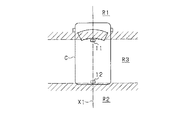
より具体的には、図2に示すように、車両Cには、例えばルーフ部分の前側部に前方カメラ11が取り付けられるとともに、ルーフ部分の後側部に後方カメラ12が取り付けられている。そして、前方カメラ11は前方範囲R1を撮影し、後方カメラ12は後方範囲R2を撮影する。前方範囲R1と後方範囲R2とは車両Cの前後方向に並んでいる。
More specifically, as shown in FIG. 2, in the vehicle C, for example, a
このため、車両Cが前進する場合には、前方カメラ11によって前方範囲R1として撮影された範囲が、車両Cの前進に伴い、後方カメラ12によって後方範囲R2として撮影される。また、車両Cが後退する場合には、後方カメラ12によって後方範囲R2として撮影された範囲が、車両Cの後退に伴い、前方カメラ11によって前方範囲R1として撮影される。なお、前方カメラ11及び後方カメラ12は、いずれも車両Cの前後方向に延びる同一線上(中心線X1上)に配置されており、その中心線X1を撮影中心として車両前方及び車両後方を撮影する。
For this reason, when the vehicle C moves forward, the range shot as the front range R1 by the
前方カメラ11はそれよりも車両後方側の撮影が不可であり、後方カメラ12はそれよりも車両前方側の撮影が不可である。そのため、車両Cの左右の側方部は、両カメラ11,12の視野外となる範囲R3(中間領域)となっている。また、各カメラ11,12は、水平方向よりも下向きで車両前方、車両後方をそれぞれ撮影し、地上面の撮影が可能になっている。
The
図1の説明に戻り、車載モニタ14は、車室内においてドライバが運転中に視認可能な位置、例えばインパネ部に設けられている。車載モニタ14の形状及び大きさは任意でよいが、本実施形態では、自車両を中心としてその前後両方の領域を含む範囲で車両周辺画像を車載モニタ14に表示することから、車載モニタ14の表示画面に縦長の表示エリアが設定されている。なお、車載モニタ14には、車両周辺画像以外の情報を表示することが可能であり、車載モニタ14に車両周辺画像を表示しない場合には、その表示画面に車両前方画像(例えば車両前方の暗視画像)や、GPSセンサ15の取得した車両Cの位置に基づくナビゲーション画像などの撮影画像以外の各種情報が表示されるとよい。
Returning to the description of FIG. 1, the in-
画像処理ユニット13は、各カメラ11,12の撮影データを合成して表示画像を作成し、その表示画像を車載モニタ14に表示させる画像処理装置である。画像処理ユニット13は、前方カメラ11の撮影データを入力する第1変換回路21と、後方カメラ12の撮影データを入力する第2変換回路22とを有しており、これら各変換回路21,22は、前方カメラ11及び後方カメラ12の各撮影データについてそれぞれ透視変換を行い、鳥瞰画像を作成する。鳥瞰画像は、各カメラ11,12の撮影範囲を上空位置から鉛直方向に見下ろした状態の俯瞰画像である。各変換回路21,22により、それぞれ前方鳥瞰画像、後方鳥瞰画像が作成される。
The
各カメラ11,12は、所定時間ごとに車両前方及び車両後方をそれぞれ撮影するものであり、各変換回路21,22によれば、所定時間ごとに車両前方の鳥瞰画像と車両後方の鳥瞰画像とが得られるようになっている。
Each of the
各変換回路21,22における透視変換について補足の説明をする。図3に示すように、地上面から高さhの位置に設けられた前方カメラ11で地上面を撮影する場合、撮影画像として、カメラ位置から所定の焦点距離fにあるスクリーン平面T上の撮影画像が得られる。この場合、前方カメラ11が地上平面を撮影することは、地上平面座標からスクリーン平面T上の二次元座標への透視変換が実行されることと等しい。そこで、各変換回路21,22では、各カメラ11,12によって撮影された撮影画像に対して、上記透視変換と逆の透視変換を行うことで、スクリーン平面T上の座標から地上平面上の座標への変換を行い、それにより地上面上の画像である鳥瞰画像(図3のPの範囲の平面画像)を作成する。
Supplementary explanation will be given for the perspective transformation in each of the
各変換回路21,22により作成された鳥瞰画像の画像データはCPU23に入力される。画像処理ユニット13は、前方鳥瞰画像と後方鳥瞰画像とに基づいて車両周辺画像を作成する。この車両周辺画像は、各変換回路21,22での変換後の画像と同様、鳥瞰画像として作成される。
The image data of the bird's-eye view image created by the
本実施形態の画像表示システムでは、自車両の周辺(車両側方)にカメラ視野外の範囲R3が含まれるため、そのカメラ視野外の範囲R3については、前方カメラ11の撮影画像(前方鳥瞰画像)、及び後方カメラ12の撮影画像(後方鳥瞰画像)のいずれかの過去画像を用いることとしている。そして、過去画像を用いて車両周辺画像を作成するための構成として、画像処理ユニット13は、過去画像を記憶する記憶手段としての画像メモリ24を有している。また、車両Cは、車速を検出する車速センサ16と、ヨーレイト(旋回方向への回転角の変化速度)を検出するヨーレイトセンサ17とを備えている。
In the image display system of the present embodiment, the range R3 outside the camera field of view is included in the vicinity (side of the vehicle) of the host vehicle, and therefore, the range R3 outside the camera field of view is taken by the front camera 11 (front bird's-eye view image). ) And any past image of the image captured by the rear camera 12 (rear bird's-eye view image). As a configuration for creating a vehicle peripheral image using a past image, the
車速センサ16及びヨーレイトセンサ17の検出信号はCPU23に逐次入力される。第1取得手段としての画像処理ユニット13は、これら各センサ16,17の検出信号(車速パルス及びヨーレイト信号)に基づいて、車両Cの走行状態である車速及びヨーレイトを算出して取得する。このとき要は、各カメラ11,12での撮影時における車両Cの走行状態が把握できればよく、車両Cの移動距離及び回転角、或いは車両Cの位置及び向きが算出されればよい。また、画像処理ユニット13は、所定時間ごとに、前方鳥瞰画像の過去画像と後方鳥瞰画像の過去画像とを、画像撮影時の車両Cの走行情報(車速やヨーレイト)に対応付けて画像メモリ24に記憶する。
Detection signals from the
画像作成手段としてのCPU23が車両周辺画像を作成する場合に、車両Cが前進しているのであれば、カメラ視野外の範囲R3の画像として、前方カメラ11により過去に撮影された撮影画像(前方過去画像)が画像メモリ24から読み出される。そして、各カメラ11,12による今現在の撮影画像(前方現在画像及び後方現在画像)と前方過去画像とにより車両周辺画像が作成される。また、車両Cが後退しているのであれば、カメラ視野外の範囲R3の画像として、後方カメラ12により過去に撮影された撮影画像(後方過去画像)が画像メモリ24から読み出される。そして、各カメラ11,12による今現在の撮影画像(前方現在画像及び後方現在画像)と後方過去画像とにより車両周辺画像が作成される。
When the
車両周辺画像の作成に際し、画像処理ユニット13は、前方現在画像と後方現在画像と前方過去画像(又は後方過去画像)とを、同一平面上において車両前後方向に並べて配置し繋ぎ合わせる。このとき、今現在の車両Cの走行状態(車速やヨーレイト)と、過去画像が撮影された時の車両Cの走行状態(車速やヨーレイト)とに基づいて、過去画像の平行移動及び回転(ユークリッド変換)を行い、各画像を一画像として合成する。
When creating the vehicle peripheral image, the
上述した通り、現在画像と過去画像との合成では、過去画像が撮影された時点から現在までの車両Cの移動量に応じて、過去画像を平行移動及び回転させて現在画像との合成を行う。車両Cの移動量の算出に用いられる車速センサ16は、車両Cのプロペラシャフトやドライブシャフトなどに対して歯車状に設けられている磁石と磁界の変化を検出する磁気センサ(ピックアップ)とから構成されており、プロペラシャフトやドライブシャフトの回転を車速パルスとして出力する。この車速パルスには、プロペラシャフトやドライブシャフトの回転方向、即ち、車両Cの進行方向についての情報が含まれていない。ヨーレイトセンサ17による検出値についても、車両Cの進行方向についての情報が含まれていない。つまり、車両Cの移動量を算出するためには、車速センサ16及びヨーレイトセンサ17の検出値とは異なる別の入力値を用いて、車両Cの進行方向を取得する必要がある。
As described above, in the synthesis of the current image and the past image, the past image is translated and rotated in accordance with the movement amount of the vehicle C from the time when the past image was taken to the present, and the current image and the past image are synthesized. . The
車両Cの進行方向を取得する方法として、車両Cのシフトレバー19の位置(シフトポジション)に基づいて判定する方法が考えられる。なお、本実施形態における車両Cの変速機構はオートマチックトランスミッションである。しかしながら、路面勾配にともなって車両Cが傾斜していると、シフトポジションがドライブであるにも関わらず後退することや、シフトポジションがリバースであるにも関わらず前進することが考えられる。このため、車両Cのシフトポジションに基づいて車両Cの進行方向を取得する方法では、画像合成において不都合が生じる可能性がある。
As a method of acquiring the traveling direction of the vehicle C, a method of determining based on the position (shift position) of the
そこで、第2取得手段としての画像処理ユニット13は、シフトポジションに加えて、加速度センサ18(加速度検出手段)により検出される車両Cの加速度を取得する。加速度センサ18は、車両停止状態における出力値(重力加速度)をオフセットとして、車両Cが前方に加速している場合にオフセット+正の値(前方への加速度)を、車両Cが後方に加速している場合にオフセット+負の値(後方への加速度)を出力する。そこで、画像処理ユニット13は、加速度センサ18の出力値からオフセット(重力加速度)を引いた値を車両Cの加速度として取得する。そして、方向判定手段としての画像処理ユニット13は、その第2取得手段の取得値である加速度に基づいて、車両Cの進行方向を判定する。そして、その進行方向に基づいて画像合成が実施される。ここで、加速度センサ18のサンプリング周期は、50msであり、表示画像の更新周期(33ms)と同程度である。
Therefore, the
図4に、本実施形態における画像合成処理を表すフローチャートを示す。この処理は、画像処理ユニット13によって周期的に実施される。
FIG. 4 is a flowchart showing the image composition processing in this embodiment. This process is periodically performed by the
ステップS01において、車速センサ16から車速パルスが入力されているか否かを判定する。車速パルスが入力されていない場合(S01:NO)、画像合成を行うことなく処理を終了する。車速パルスが入力されている場合(S01:YES)、ステップS02において、車両Cの傾斜(道路勾配)が所定傾斜以上の急傾斜(−10%以下、又は、+10%以上)であるか否かを判定する。ここで、車両Cの傾斜は、傾斜検出手段としての加速度センサ18のオフセット(DC成分)として取得される重力加速度に基づいて算出することができる。
In step S01, it is determined whether or not a vehicle speed pulse is input from the
車両Cの傾斜が所定傾斜以上の急傾斜である場合(S02:YES)、ステップS03において、車速パルスに基づき取得される車速が所定の範囲(10km/h以下)に属するか否かを判定する。車速が所定の範囲に属する場合(S03:YES)、ステップS04において、加速度センサ18によって検出される加速度の分散を取得し、その分散が所定値以下か否かを判定する。
When the inclination of the vehicle C is a steep inclination greater than or equal to a predetermined inclination (S02: YES), it is determined in step S03 whether or not the vehicle speed acquired based on the vehicle speed pulse belongs to a predetermined range (10 km / h or less). . When the vehicle speed belongs to the predetermined range (S03: YES), in step S04, the variance of the acceleration detected by the
加速度の分散が所定値以下である場合(S04:YES)、即ち、加速度センサ18の検出値が信頼できる場合、ステップS05において、加速度に基づいて進行方向の判定を行う。加速度に基づく進行方向の判定処理の詳細については後述する。
When the variance of acceleration is equal to or less than a predetermined value (S04: YES), that is, when the detected value of the
車両Cの傾斜が所定傾斜以上の急傾斜でない場合(S02:NO)、車速が所定の範囲外(10km/hより大)に属する場合(S03:NO)、又は、加速度の分散が所定値より大きい場合(S04:NO)、ステップS06において、シフトポジションに基づいて車両Cの進行方向を取得する。即ち、シフトポジションがドライブである場合は、車両Cが前進していると判定し、リバースである場合は、車両Cが後退していると判定する。 When the inclination of the vehicle C is not steep than a predetermined inclination (S02: NO), when the vehicle speed belongs outside the predetermined range (greater than 10 km / h) (S03: NO), or when the acceleration variance is greater than the predetermined value If larger (S04: NO), the traveling direction of the vehicle C is acquired based on the shift position in step S06. That is, when the shift position is drive, it is determined that the vehicle C is moving forward, and when it is reverse, it is determined that the vehicle C is moving backward.
ステップS05及びステップS06の後、ステップS07において、車速センサ16から取得した車速、ヨーレイトセンサ17から取得したヨーレイト、及び、ステップS05又はS06において取得した車両Cの進行方向に基づいて、画像合成を実施し、処理を終了する。
After step S05 and step S06, in step S07, image synthesis is performed based on the vehicle speed acquired from the
図5に加速度センサ18の検出値に基づく進行方向の判定を表すフローチャートを示す。
FIG. 5 is a flowchart showing the determination of the traveling direction based on the detection value of the
ステップS11において、車両Cの発進後、所定時間が経過しているか否かを判定する。車両Cの発進後、所定時間が経過していない場合(S11:NO)、ステップS12において、加速度センサ18による検出値である加速度が正の値であるか否かを判定する。加速度が正の値である場合(S12:YES)、ステップS13において、車両Cが前進していると判定する。加速度が負の値である場合(S12:NO)、ステップS14において、車両Cが後退していると判定する。つまり、停車状態から発進する状況において、加速度が正の場合は車両Cが前進していると判定し、加速度が負の場合は車両Cが後退していると判定する。
In step S11, it is determined whether or not a predetermined time has elapsed after the vehicle C starts. If the predetermined time has not elapsed since the vehicle C started (S11: NO), it is determined in step S12 whether or not the acceleration detected by the
車両Cの発進後、所定時間が経過している場合、ステップS15において、車速が増加しているか否かを判定する。車速が増加している場合(S15:YES)、ステップS16において、加速度が正の値であるか否かを判定する。加速度が正の値である場合(S16:YES)、ステップS17において、車両Cが前進していると判定する。加速度が負の値である場合(S16:NO)、ステップS18において、車両Cが後退していると判定する。車速が減少している場合(S15:NO)、ステップS19において、加速度が正の値であるか否かを判定する。加速度が正の値である場合(S19:YES)、ステップS20において、車両Cが後退していると判定する。加速度が負の値である(S19:NO)、ステップS21において、車両Cが前進していると判定する。 If the predetermined time has elapsed after the vehicle C has started, it is determined in step S15 whether or not the vehicle speed has increased. If the vehicle speed is increasing (S15: YES), it is determined in step S16 whether or not the acceleration is a positive value. When the acceleration is a positive value (S16: YES), it is determined in step S17 that the vehicle C is moving forward. If the acceleration is a negative value (S16: NO), it is determined in step S18 that the vehicle C is moving backward. If the vehicle speed is decreasing (S15: NO), it is determined in step S19 whether or not the acceleration is a positive value. If the acceleration is a positive value (S19: YES), it is determined in step S20 that the vehicle C is moving backward. If the acceleration is a negative value (S19: NO), it is determined in step S21 that the vehicle C is moving forward.
例えば、登り方向の急斜面において車両Cが後退し続けている状況では、車速(車速の絶対値)が増加するとともに、加速度が負の値となる。ここで、ドライバによるブレーキペダルの操作によって、車両Cが後退し続けるとともに、車速(車速の絶対値)が減少するような状況が考えられる。この状況では、車速が減少するとともに、加速度が正の値となる。同様に、下り方向の急斜面において車両Cが前進し続けている状況では、車速(車速の絶対値)が増加するとともに、加速度が正の値となる。ここで、ドライバによるブレーキペダルの操作によって、車両Cが前進し続けるとともに、車速(車速の絶対値)が減少するような状況が考えられる。この状況では、車速が減少するとともに、加速度が負の値となる。ステップS15〜S21における進行方向の判定によれば、車両Cが斜面上で前進又は後退し続けている場合に、正しく進行方向を判定することができる。 For example, in a situation where the vehicle C continues to retreat on a steep slope in the climbing direction, the vehicle speed (absolute value of the vehicle speed) increases and the acceleration becomes a negative value. Here, a situation is conceivable in which the vehicle C continues to move backward and the vehicle speed (absolute value of the vehicle speed) decreases as the driver operates the brake pedal. In this situation, the vehicle speed decreases and the acceleration becomes a positive value. Similarly, in a situation where the vehicle C continues to advance on a steep slope in the downward direction, the vehicle speed (absolute value of the vehicle speed) increases and the acceleration becomes a positive value. Here, a situation is conceivable in which the vehicle C continues to move forward and the vehicle speed (absolute value of the vehicle speed) decreases as the driver operates the brake pedal. In this situation, the vehicle speed decreases and the acceleration becomes a negative value. According to the determination of the traveling direction in steps S15 to S21, the traveling direction can be correctly determined when the vehicle C continues to move forward or backward on the slope.
以下、本実施形態の効果を述べる。 The effects of this embodiment will be described below.
車両Cの実際の進行態様に基づいて進行方向を判定する構成とした。そして、車速パルスに基づいて取得される車速に加えて、実際の進行態様に基づいて判定される進行方向を用いて、画像合成を実施する構成とした。このような構成にすることで、例えば、シフトポジションがドライブであるにも関わらず後退している状況下や、シフトポジションがリバースであるにも関わらず前進している状況下であっても、現在画像と過去画像とを好適に合成することができる。 The traveling direction is determined based on the actual traveling mode of the vehicle C. And it was set as the structure which implements an image composition using the advancing direction determined based on the actual advancing aspect in addition to the vehicle speed acquired based on a vehicle speed pulse. By adopting such a configuration, for example, even in a situation where the shift position is reverse despite being a drive, or in a situation where the shift position is reverse but being forward, The current image and the past image can be suitably combined.
本実施形態では、実際の進行態様に基づいて判定される進行方向と、シフトポジションに基づいて取得される進行方向との双方を用いる構成とした。この構成により、現在画像と過去画像とをより好適に合成することが可能になる。 In the present embodiment, both the traveling direction determined based on the actual traveling mode and the traveling direction acquired based on the shift position are used. With this configuration, the current image and the past image can be combined more suitably.
具体的には、加速度センサ18により検出される加速度の分散が大きい場合、即ち、加速度センサ18の検出値の信頼度が低い場合は、シフトポジションに基づいて取得される進行方向に基づいて画像合成を実施する構成とした。このような構成にすることで、進行方向について信頼度の高い判定結果を用いて画像合成を実施することができる。
Specifically, when the dispersion of acceleration detected by the
また、車両Cの傾斜(即ち、道路勾配)が急傾斜である場合において、シフトポジションがドライブに入っているにも関わらず、車両Cが後退するという状況が発生し易いと考えられる。そこで、車両Cの傾斜が所定傾斜以上の急傾斜(例えば、−10%以下及び10%以上)であることを条件として、方向判定手段としての画像処理ユニット13により判定される実際の進行方向に基づいて、画像合成を実施する構成にした。このような構成にすることで、シフトポジションに基づいて取得される進行方向の信頼度が低い状況下で、加速度センサ18に基づいて取得される進行方向を用いた画像合成が実施されることになり、より好適な画像合成を実施することが可能になる。
Further, when the inclination of the vehicle C (that is, the road gradient) is steep, it is considered that the situation where the vehicle C moves backward is likely to occur although the shift position is in the drive. Therefore, on the condition that the inclination of the vehicle C is a steep inclination greater than or equal to a predetermined inclination (for example, −10% or less and 10% or more), the actual traveling direction is determined by the
また、坂道発進時などの車速が小さい場合において、シフトポジションがドライブに入っているにも関わらず、車両Cが後退するという状況が発生し易いと考えられる。そこで、車速が所定値より小さいことを条件として、方向判定手段としての画像処理ユニット13により判定される進行方向に基づいて、画像合成を行う構成とした。このような構成にすることで、シフトポジションに基づいて取得される進行方向の信頼度が低い状況下で、加速度センサ18に基づいて取得される進行方向を用いた画像合成が実施されることになり、より好適な画像合成を実施することが可能になる。
In addition, when the vehicle speed is low, such as when starting on a slope, it is considered that a situation in which the vehicle C moves backward despite the shift position being in the drive is likely to occur. Therefore, on the condition that the vehicle speed is smaller than a predetermined value, the image composition is performed based on the traveling direction determined by the
(他の実施形態)
・上記の実施形態の画像処理ユニット13は、加速度センサ18の検出値を用いて、車両Cの実際の進行方向を判定する構成とした。これを変更し、画像処理ユニットが、位置取得手段としてのGPSセンサ15(図1)がGPS衛星から受信したGPS信号に基づいて車両Cの位置を取得する。そして、その車両Cの位置の変化に基づいて、車両Cの実際の進行方向を判定する構成としてもよい。
(Other embodiments)
The
また、GPSセンサ15、車速センサ16、ヨーレイトセンサ17、及び、加速度センサ18の検出値を入力値とするカルマンフィルタに基づく自己位置推定に基づいて、画像処理ユニット13が車両Cの実際の進行方向を判定する構成としてもよい。
Further, the
GPS信号に基づく車両Cの位置、及び、自己位置推定に基づく車両Cの位置について、所定期間において取得された車両Cの位置の分散が大きい場合は、シフトポジションに基づいて取得される進行方向を優先して、画像合成を行う構成とするとよい。 For the position of the vehicle C based on the GPS signal and the position of the vehicle C based on the self-position estimation, when the variance of the position of the vehicle C acquired in a predetermined period is large, the traveling direction acquired based on the shift position is A configuration in which image composition is performed with priority is preferable.
・車両Cの傾斜が所定傾斜以上の急傾斜である場合や、車速が所定の範囲に属する場合に、加速度による進行方向の判定を実施する構成としたが、これを変更してもよい。具体的には、車両Cの傾斜や車速に関わらず、加速度に基づく進行方向の判定を実施してもよい。また、加速度の分散によらず、加速度に基づく進行方向の判定を実施してもよい。 -Although it was set as the structure which performs the determination of the advancing direction by acceleration, when the inclination of the vehicle C is a steep inclination more than predetermined inclination, or when a vehicle speed belongs to the predetermined range, you may change this. Specifically, the determination of the traveling direction based on the acceleration may be performed regardless of the inclination of the vehicle C and the vehicle speed. Moreover, you may implement the determination of the advancing direction based on acceleration irrespective of dispersion | distribution of acceleration.
・上記実施形態の車両の変速機構は、オートマチックトランスミッションであるとしたが、これを変更し、マニュアルトランスミッションであってもよい。 -Although the transmission mechanism of the vehicle of the said embodiment was an automatic transmission, it changed this and a manual transmission may be sufficient.
・シフトポジションに基づいて取得される進行方向に代えて、ドライバの挙動や視線をカメラにより取得し、その挙動や視線に基づいて、車両Cの進行方向を取得する構成としてもよい。 Instead of the traveling direction acquired based on the shift position, the driver's behavior and line of sight may be acquired by a camera, and the traveling direction of the vehicle C may be acquired based on the behavior and line of sight.
・撮影手段としてのカメラを前方及び後方の2個備える上記実施形態の構成に代えて、1個備える構成であってもよいし、3個以上備える構成であってもよい。 -Instead of the structure of the said embodiment provided with two cameras as imaging | photography means on the front and back, the structure provided with one may be sufficient, and the structure provided with three or more may be sufficient.
11…前方カメラ(撮影手段)、12…後方カメラ(撮影手段)、13…画像処理ユニット(車両用画像処理装置、第1取得手段、第2取得手段、画像作成手段、方向判定手段)、14…車載モニタ(表示手段)、24…画像メモリ(記憶手段)、C…車両。
DESCRIPTION OF
Claims (7)
前記撮影手段の撮影時における走行状態として、車速パルスに基づいて車速を取得する第1取得手段と、
前記撮影画像が過去画像として記憶される記憶手段(24)と、
前記第1取得手段により取得した走行状態に基づいて、前記記憶手段に記憶されている過去画像と前記撮影手段により撮影されている現在画像とを合成し、前記表示手段に表示する表示画像を作成する画像作成手段(23)と、
前記車両の実際の進行態様を取得する第2取得手段の取得値に基づいて、前記車両の進行方向を判定する方向判定手段と、
を備え、
前記画像作成手段は、前記第1取得手段が取得した走行状態に加えて、前記方向判定手段により判定される進行方向に基づいて、前記過去画像と前記現在画像とを合成し、
前記第1取得手段は、前記車速に加えて、前記車両のシフトポジションに基づいて前記車両の進行方向を前記走行状態として取得し、
前記画像作成手段は、前記第2取得手段による取得値の分散が所定値より大きいことを条件として、前記方向判定手段により判定される進行方向を用いることなく、前記第1取得手段が取得した進行方向を用いて、前記過去画像と前記現在画像とを合成することを特徴とする車両用画像処理装置。 The present invention is applied to a vehicle provided with photographing means (11, 12) for photographing a predetermined range around the vehicle (C) and display means (14) for displaying a photographed image photographed by the photographing means, and is mounted on the vehicle. A vehicle image processing device (13),
A first acquisition unit that acquires a vehicle speed based on a vehicle speed pulse as a running state at the time of shooting by the shooting unit;
Storage means (24) for storing the photographed image as a past image;
Based on the running state acquired by the first acquisition unit, the past image stored in the storage unit and the current image captured by the imaging unit are combined to create a display image to be displayed on the display unit. Image creating means (23) to perform,
Direction determining means for determining a traveling direction of the vehicle based on an acquired value of a second acquiring means for acquiring an actual traveling mode of the vehicle;
With
The image creating means combines the past image and the current image based on the traveling direction determined by the direction determining means in addition to the traveling state acquired by the first acquiring means ,
The first acquisition means acquires the traveling direction of the vehicle as the traveling state based on a shift position of the vehicle in addition to the vehicle speed,
The image creation means, on the condition that the dispersion of the acquired values by the second acquisition means is larger than a predetermined value, the progress acquired by the first acquisition means without using the traveling direction determined by the direction determination means. An image processing apparatus for a vehicle , wherein the past image and the current image are synthesized using a direction .
前記画像作成手段は、前記傾斜が所定傾斜以上の急傾斜であることを条件として、前記車両のシフトポジションに基づいて取得される進行方向を用いることなく、前記方向判定手段により判定される進行方向を用いて、前記過去画像と前記現在画像とを合成することを特徴とする請求項1に記載の車両用画像処理装置。 The second acquisition means acquires the inclination from an inclination detection means (18) for detecting the inclination of the vehicle,
The image creating means is a traveling direction determined by the direction determining means without using a traveling direction acquired based on the shift position of the vehicle on the condition that the inclination is a steep inclination equal to or greater than a predetermined inclination. using, image processing system as recited in claim 1, wherein the synthesis of said previous image and the current image.
前記撮影手段の撮影時における走行状態として、車速パルスに基づいて車速を取得する第1取得手段と、A first acquisition unit that acquires a vehicle speed based on a vehicle speed pulse as a running state at the time of shooting by the shooting unit;
前記撮影画像が過去画像として記憶される記憶手段(24)と、Storage means (24) for storing the photographed image as a past image;
前記第1取得手段により取得した走行状態に基づいて、前記記憶手段に記憶されている過去画像と前記撮影手段により撮影されている現在画像とを合成し、前記表示手段に表示する表示画像を作成する画像作成手段(23)と、Based on the running state acquired by the first acquisition unit, the past image stored in the storage unit and the current image captured by the imaging unit are combined to create a display image to be displayed on the display unit. Image creating means (23) to perform,
前記車両の実際の進行態様を取得する第2取得手段の取得値に基づいて、前記車両の進行方向を判定する方向判定手段と、Direction determining means for determining a traveling direction of the vehicle based on an acquired value of a second acquiring means for acquiring an actual traveling mode of the vehicle;
を備え、With
前記画像作成手段は、前記第1取得手段が取得した走行状態に加えて、前記方向判定手段により判定される進行方向に基づいて、前記過去画像と前記現在画像とを合成し、The image creating means combines the past image and the current image based on the traveling direction determined by the direction determining means in addition to the traveling state acquired by the first acquiring means,
前記第1取得手段は、前記車速に加えて、前記車両のシフトポジションに基づいて前記車両の進行方向を前記走行状態として取得し、The first acquisition means acquires the traveling direction of the vehicle as the traveling state based on a shift position of the vehicle in addition to the vehicle speed,
前記第2取得手段は、前記車両の傾斜を検出する傾斜検出手段(18)から前記傾斜を取得し、The second acquisition means acquires the inclination from an inclination detection means (18) for detecting the inclination of the vehicle,
前記画像作成手段は、前記傾斜が所定傾斜以上の急傾斜であることを条件として、前記車両のシフトポジションに基づいて取得される進行方向を用いることなく、前記方向判定手段により判定される進行方向を用いて、前記過去画像と前記現在画像とを合成することを特徴とする車両用画像処理装置。The image creating means is a traveling direction determined by the direction determining means without using a traveling direction acquired based on the shift position of the vehicle on the condition that the inclination is a steep inclination equal to or greater than a predetermined inclination. The vehicular image processing apparatus characterized in that the past image and the current image are synthesized using a computer.
前記撮影手段の撮影時における走行状態として、車速パルスに基づいて車速を取得する第1取得手段と、A first acquisition unit that acquires a vehicle speed based on a vehicle speed pulse as a running state at the time of shooting by the shooting unit;
前記撮影画像が過去画像として記憶される記憶手段(24)と、Storage means (24) for storing the photographed image as a past image;
前記第1取得手段により取得した走行状態に基づいて、前記記憶手段に記憶されている過去画像と前記撮影手段により撮影されている現在画像とを合成し、前記表示手段に表示する表示画像を作成する画像作成手段(23)と、Based on the running state acquired by the first acquisition unit, the past image stored in the storage unit and the current image captured by the imaging unit are combined to create a display image to be displayed on the display unit. Image creating means (23) to perform,
前記車両の実際の進行態様を取得する第2取得手段の取得値に基づいて、前記車両の進行方向を判定する方向判定手段と、Direction determining means for determining a traveling direction of the vehicle based on an acquired value of a second acquiring means for acquiring an actual traveling mode of the vehicle;
を備え、With
前記画像作成手段は、前記第1取得手段が取得した走行状態に加えて、前記方向判定手段により判定される進行方向に基づいて、前記過去画像と前記現在画像とを合成し、The image creating means combines the past image and the current image based on the traveling direction determined by the direction determining means in addition to the traveling state acquired by the first acquiring means,
前記第1取得手段は、前記車速に加えて、前記車両のシフトポジションに基づいて前記車両の進行方向を前記走行状態として取得し、The first acquisition means acquires the traveling direction of the vehicle as the traveling state based on a shift position of the vehicle in addition to the vehicle speed,
前記画像作成手段は、前記車速が所定値より小さいことを条件として、前記車両のシフトポジションに基づいて取得される進行方向を用いることなく、前記方向判定手段により判定される進行方向を用いて、前記過去画像と前記現在画像とを合成することを特徴とする車両用画像処理装置。The image creating means uses the traveling direction determined by the direction determining means, without using the traveling direction acquired based on the shift position of the vehicle, on condition that the vehicle speed is smaller than a predetermined value. An image processing apparatus for a vehicle, wherein the past image and the current image are synthesized.
前記方向判定手段は、前記加速度に基づいて、前記車両の進行方向を判定することを特徴とする請求項1乃至5のいずれか1項に記載の車両用画像処理装置。 The second acquisition means acquires the acceleration from an acceleration detection means (18) for detecting acceleration generated in the vehicle,
The vehicle image processing apparatus according to claim 1, wherein the direction determination unit determines a traveling direction of the vehicle based on the acceleration.
前記方向判定手段は、前記位置の変化に基づいて、前記車両の進行方向を判定することを特徴とする請求項1乃至5のいずれか1項に記載の車両用画像処理装置。 The second acquisition means acquires the position from a position acquisition means (15) that receives a GPS signal from a GPS satellite and acquires the position of the vehicle,
The vehicle image processing apparatus according to claim 1, wherein the direction determination unit determines a traveling direction of the vehicle based on the change in the position.
Priority Applications (4)
| Application Number | Priority Date | Filing Date | Title |
|---|---|---|---|
| JP2014193542A JP6361415B2 (en) | 2014-09-24 | 2014-09-24 | Image processing apparatus for vehicle |
| CN201580037396.XA CN106664392A (en) | 2014-09-24 | 2015-08-25 | Vehicular image-processing apparatus |
| PCT/JP2015/004256 WO2016047037A1 (en) | 2014-09-24 | 2015-08-25 | Vehicular image-processing apparatus |
| DE112015004341.1T DE112015004341B4 (en) | 2014-09-24 | 2015-08-25 | VEHICLE IMAGE PROCESSING DEVICE |
Applications Claiming Priority (1)
| Application Number | Priority Date | Filing Date | Title |
|---|---|---|---|
| JP2014193542A JP6361415B2 (en) | 2014-09-24 | 2014-09-24 | Image processing apparatus for vehicle |
Publications (3)
| Publication Number | Publication Date |
|---|---|
| JP2016066855A JP2016066855A (en) | 2016-04-28 |
| JP2016066855A5 JP2016066855A5 (en) | 2016-08-04 |
| JP6361415B2 true JP6361415B2 (en) | 2018-07-25 |
Family
ID=55580591
Family Applications (1)
| Application Number | Title | Priority Date | Filing Date |
|---|---|---|---|
| JP2014193542A Active JP6361415B2 (en) | 2014-09-24 | 2014-09-24 | Image processing apparatus for vehicle |
Country Status (4)
| Country | Link |
|---|---|
| JP (1) | JP6361415B2 (en) |
| CN (1) | CN106664392A (en) |
| DE (1) | DE112015004341B4 (en) |
| WO (1) | WO2016047037A1 (en) |
Families Citing this family (3)
| Publication number | Priority date | Publication date | Assignee | Title |
|---|---|---|---|---|
| JP7130994B2 (en) * | 2018-03-12 | 2022-09-06 | オムロン株式会社 | In-vehicle device, backward determination method, and backward determination program |
| US10567724B2 (en) * | 2018-04-10 | 2020-02-18 | GM Global Technology Operations LLC | Dynamic demosaicing of camera pixels |
| JP7184591B2 (en) * | 2018-10-15 | 2022-12-06 | 三菱重工業株式会社 | Vehicle image processing device, vehicle image processing method, program and storage medium |
Family Cites Families (10)
| Publication number | Priority date | Publication date | Assignee | Title |
|---|---|---|---|---|
| JP3722487B1 (en) * | 2004-05-19 | 2005-11-30 | 本田技研工業株式会社 | Vehicle lane marking recognition device |
| JP4561470B2 (en) * | 2005-05-19 | 2010-10-13 | アイシン・エィ・ダブリュ株式会社 | Parking assistance device |
| JP4595680B2 (en) * | 2005-05-27 | 2010-12-08 | アイシン・エィ・ダブリュ株式会社 | Parking support method and parking support device |
| JP2007099261A (en) | 2005-09-12 | 2007-04-19 | Aisin Aw Co Ltd | Parking assistance method and parking assistance device |
| JP2007114020A (en) * | 2005-10-19 | 2007-05-10 | Aisin Aw Co Ltd | Vehicle moving distance detecting method and device, and current vehicle position detecting method and device |
| JP4321543B2 (en) | 2006-04-12 | 2009-08-26 | トヨタ自動車株式会社 | Vehicle periphery monitoring device |
| JP5500369B2 (en) * | 2009-08-03 | 2014-05-21 | アイシン精機株式会社 | Vehicle peripheral image generation device |
| JP2011152865A (en) * | 2010-01-27 | 2011-08-11 | Kyocera Corp | On-vehicle image pickup device |
| JP5858650B2 (en) * | 2011-06-08 | 2016-02-10 | 富士通テン株式会社 | Image generation apparatus, image display system, and image generation method |
| JP5790335B2 (en) | 2011-09-01 | 2015-10-07 | 株式会社デンソー | Vehicle peripheral image display control device |
-
2014
- 2014-09-24 JP JP2014193542A patent/JP6361415B2/en active Active
-
2015
- 2015-08-25 DE DE112015004341.1T patent/DE112015004341B4/en active Active
- 2015-08-25 CN CN201580037396.XA patent/CN106664392A/en active Pending
- 2015-08-25 WO PCT/JP2015/004256 patent/WO2016047037A1/en active Application Filing
Also Published As
| Publication number | Publication date |
|---|---|
| JP2016066855A (en) | 2016-04-28 |
| WO2016047037A1 (en) | 2016-03-31 |
| DE112015004341B4 (en) | 2022-03-10 |
| DE112015004341T5 (en) | 2017-06-08 |
| CN106664392A (en) | 2017-05-10 |
Similar Documents
| Publication | Publication Date | Title |
|---|---|---|
| JP4863791B2 (en) | Vehicle peripheral image generation apparatus and image switching method | |
| JP6477562B2 (en) | Information processing device | |
| JP2002373327A (en) | Apparatus for processing image around vehicle and recording medium | |
| JP2007325166A (en) | Parking support program, parking supporting apparatus, and parking supporting screen | |
| JP6597415B2 (en) | Information processing apparatus and program | |
| JP2016066322A (en) | Image processor and image display system | |
| JP5548069B2 (en) | Image processing apparatus and image processing method | |
| JP6361415B2 (en) | Image processing apparatus for vehicle | |
| JP6326869B2 (en) | Vehicle periphery image display device and vehicle periphery image display method | |
| JP2011235677A (en) | Parking support system and navigation device | |
| JP4932293B2 (en) | Obstacle recognition device | |
| JP6375633B2 (en) | Vehicle periphery image display device and vehicle periphery image display method | |
| JP6852465B2 (en) | Bird's-eye view image generation device, bird's-eye view image generation system, bird's-eye view image generation method and program | |
| JP2010233080A (en) | Driving support device, driving support method, and driving support program | |
| JP2016066855A5 (en) | ||
| JP4857159B2 (en) | Vehicle driving support device | |
| JP4557712B2 (en) | Driving support system | |
| JP5132796B2 (en) | Vehicle peripheral image generation apparatus and image switching method | |
| JP2001341600A (en) | Parking support device | |
| JP2009065472A (en) | Device, method, and program for photographing running image | |
| JP6572862B2 (en) | Display control device | |
| JP2010237797A (en) | Image processor and image processing program | |
| JP2022126659A (en) | Vehicle image processing device, vehicle image processing system, vehicle image processing method, and program | |
| JP2013015882A (en) | Image recognition device for vehicle | |
| JP3947117B2 (en) | Vehicle periphery image processing system |
Legal Events
| Date | Code | Title | Description |
|---|---|---|---|
| A521 | Request for written amendment filed |
Free format text: JAPANESE INTERMEDIATE CODE: A523 Effective date: 20160617 |
|
| A621 | Written request for application examination |
Free format text: JAPANESE INTERMEDIATE CODE: A621 Effective date: 20170328 |
|
| TRDD | Decision of grant or rejection written | ||
| A01 | Written decision to grant a patent or to grant a registration (utility model) |
Free format text: JAPANESE INTERMEDIATE CODE: A01 Effective date: 20180529 |
|
| A61 | First payment of annual fees (during grant procedure) |
Free format text: JAPANESE INTERMEDIATE CODE: A61 Effective date: 20180611 |
|
| R151 | Written notification of patent or utility model registration |
Ref document number: 6361415 Country of ref document: JP Free format text: JAPANESE INTERMEDIATE CODE: R151 |
|
| R250 | Receipt of annual fees |
Free format text: JAPANESE INTERMEDIATE CODE: R250 |
|
| R250 | Receipt of annual fees |
Free format text: JAPANESE INTERMEDIATE CODE: R250 |
|
| R250 | Receipt of annual fees |
Free format text: JAPANESE INTERMEDIATE CODE: R250 |