JP2012254815A - Packaging box - Google Patents

Packaging box Download PDF

Info

Publication number
JP2012254815A
JP2012254815A JP2011129382A JP2011129382A JP2012254815A JP 2012254815 A JP2012254815 A JP 2012254815A JP 2011129382 A JP2011129382 A JP 2011129382A JP 2011129382 A JP2011129382 A JP 2011129382A JP 2012254815 A JP2012254815 A JP 2012254815A
Authority
JP
Japan
Prior art keywords
wall
packaging box
locking
buffer
walls
Prior art date
Legal status (The legal status is an assumption and is not a legal conclusion. Google has not performed a legal analysis and makes no representation as to the accuracy of the status listed.)
Withdrawn
Application number
JP2011129382A
Other languages
Japanese (ja)
Inventor
Shuhei Kumaki
周平 熊木
Current Assignee (The listed assignees may be inaccurate. Google has not performed a legal analysis and makes no representation or warranty as to the accuracy of the list.)
Rengo Co Ltd
Original Assignee
Rengo Co Ltd
Priority date (The priority date is an assumption and is not a legal conclusion. Google has not performed a legal analysis and makes no representation as to the accuracy of the date listed.)
Filing date
Publication date
Application filed by Rengo Co Ltd filed Critical Rengo Co Ltd
Priority to JP2011129382A priority Critical patent/JP2012254815A/en
Publication of JP2012254815A publication Critical patent/JP2012254815A/en
Withdrawn legal-status Critical Current

Links

Images

Abstract

PROBLEM TO BE SOLVED: To provide a packaging box that prevents an appearance from being damaged, and has a good workability of storing commodities.SOLUTION: The packaging box 1 has a plan view quadrangle shape having end walls 10A, 10B and side walls 11A, 11B which are alternately consecutive in a lateral direction, and is consecutively provided with bottom flaps 16A, 16B, 17A, 17B for closing a bottom surface while being superposed in and out at a lower end thereof. The packaging box includes: consecutively arranging a first cushioning part 24 having a first inner wall part 26 folded into an inner surface side substantially in parallel at upper ends of respective end walls 10A, 10B; consecutively arranging second cushioning parts 33A, 33B having an upper surface part 34 extending toward the adjacent sidewalls 11A, 11B and a second inner wall part 35 folded downward from an inner edge of the upper surface part 34; arranging locking protrusions 29, 37 at a lower end edges of the first and second inner wall parts 26, 35; and arranging locking grooves 19, 20 for locking the locking protrusions 29, 37 at the inner side bottom flaps 16A, 16B which are positioned inside.

Description

本発明は、内部に平面視六角形以上の多角形状収容部を形成可能な平面視四角形状の包装箱に関するものである。   The present invention relates to a packaging box having a quadrangular shape in plan view and capable of forming a polygonal housing portion having a hexagonal shape or more in plan view.

円板状をなす商品を収容する包装箱は、平面視四角形状をなす外周壁の4隅に緩衝部を配置することにより、内部の収容部を平面視八角形状とし、商品との間に形成される空隙を少なくしている。また、別部材からなる緩衝部を包装箱に配置すると部品点数が増加するという問題がある。   A packaging box that accommodates a disc-shaped product is formed between the product by placing buffer portions at the four corners of the outer peripheral wall that has a quadrilateral shape in plan view, thereby forming the inside accommodating portion in an octagonal shape in plan view. There are few voids. Moreover, when the buffer part which consists of another member is arrange | positioned in a packaging box, there exists a problem that a number of parts will increase.

そこで、特許文献1では、中央に位置する底壁の対向する縁に端壁を連設するとともに、他の対向する縁に側壁を連設し、第1および第2緩衝部を一体に連設した包装箱を提供している。第1緩衝部は、端壁および側壁の中央に形成されており、これらの内面側に折り込まれる第1内壁部を備えている。第2緩衝部は、端壁における第1緩衝部の両側に形成されており、隣接する側壁に向けて延びる台形状の上面部と、この上面部の内縁から下向きに折り込まれる第2内壁部とを備えている。なお、側壁には、第1緩衝部の両側に第2緩衝部の上面部の内(下)側に配置される支持部が連設されている。   Therefore, in Patent Document 1, an end wall is connected to the opposite edge of the bottom wall located in the center, a side wall is connected to the other opposite edge, and the first and second buffer portions are integrally connected. We provide a packaging box. The 1st buffer part is formed in the center of an end wall and a side wall, and is provided with the 1st inner wall part folded in by these inner surface sides. The second buffer portion is formed on both sides of the first buffer portion in the end wall, and has a trapezoidal upper surface portion extending toward the adjacent side wall, and a second inner wall portion folded downward from the inner edge of the upper surface portion. It has. In addition, the support part arrange | positioned at the inner side (lower side) of the upper surface part of a 2nd buffer part is provided in a row by the both sides of the 1st buffer part.

しかしながら、この特許文献1の包装箱は、第1緩衝部を折り込んだ状態で固定するために、底壁に第1緩衝部の係止突部を係止するための係止溝を設ける必要がある。この場合、この係止溝が包装箱の外側から見えるため、外観が損なわれるだけでなく、その係止溝から塵埃が内部に侵入するという不都合がある。   However, in the packaging box of Patent Document 1, it is necessary to provide a locking groove for locking the locking protrusion of the first buffer portion on the bottom wall in order to fix the first buffer portion in a folded state. is there. In this case, since the locking groove is visible from the outside of the packaging box, not only the appearance is impaired, but there is a disadvantage that dust enters the inside from the locking groove.

一方、特許文献2では、横方向に交互に連続する端壁および側壁を有し、側壁の下端に内部に折り込まれる第1緩衝部を連設し、端壁の上端に内部に折り込まれる第2緩衝部を連設した包装箱を提供している。また、一対の端壁の下端には、底面を閉塞する底蓋フラップが連設され、一対の側壁の上端には、上面を閉塞する天蓋フラップが連設されている。この包装箱では、第1および第2緩衝部の間に円板状をなす商品を挟み込むようにして配設する。そのため、包装箱は、打ち抜いた溝が外側に存在しないため、外観が損なわれることはない。   On the other hand, in patent document 2, it has the end wall and side wall which are alternately continued in the horizontal direction, the 1st buffer part folds inside is provided in the lower end of the side wall, and it is the 2nd folded in at the upper end of the end wall inside. The packaging box which provided the buffer part continuously is provided. In addition, a bottom lid flap that closes the bottom surface is connected to the lower ends of the pair of end walls, and a canopy flap that closes the top surface is connected to the upper ends of the pair of side walls. In this packaging box, the disc-shaped product is disposed between the first and second buffer portions. For this reason, the outer appearance of the packaging box is not impaired because there is no punched groove on the outside.

しかし、この特許文献2の包装箱は、商品を第1緩衝部の上に載せ、第2緩衝部で挟み込むようにして固定するものであるため、商品の収容作業性が悪いという問題がある。   However, the packaging box disclosed in Patent Document 2 has a problem in that the accommodation workability of the product is poor because the product is placed on the first buffer portion and fixed so as to be sandwiched by the second buffer portion.

実開昭58−98311号公報Japanese Utility Model Publication No. 58-98311 特開2010−47302号公報JP 2010-47302 A

本発明は、外観が損なわれることを防止し、商品の収容作業性が良好な包装箱を提供することを課題とするものである。   It is an object of the present invention to provide a packaging box that prevents the appearance from being damaged and has good product workability.

前記課題を解決するため、本発明の包装箱は、横方向に交互に連続する各一対の端壁および側壁を有する平面視四角形状をなし、これら端壁および側壁の下端に内外に重畳した状態で底面を閉塞する底フラップを連設した包装箱において、前記各端壁の上端に、各端壁の内面側に略平行に折り込まれる第1内壁部を有する第1緩衝部を連設するとともに、隣接する前記側壁に向けて延びる上面部およびこの上面部の内縁から下向きに折り込まれる第2内壁部を有する第2緩衝部を連設し、前記第1および第2内壁部の下端縁に係止突部を設け、前記底フラップの内側に位置する部分に、前記係止突部を係止する係止溝を設けた構成としている。   In order to solve the above-mentioned problems, the packaging box of the present invention has a rectangular shape in plan view having a pair of end walls and side walls that are alternately continuous in the lateral direction, and is superimposed on the inside and outside of the lower ends of these end walls and side walls. In the packaging box in which the bottom flap for closing the bottom surface is continuously provided, a first buffer portion having a first inner wall portion that is folded substantially parallel to the inner surface side of each end wall is provided at the upper end of each end wall. A second buffer portion having an upper surface portion extending toward the adjacent side wall and a second inner wall portion folded downward from an inner edge of the upper surface portion, and being engaged with lower end edges of the first and second inner wall portions A stop protrusion is provided, and a locking groove for locking the locking protrusion is provided in a portion located inside the bottom flap.

本発明の包装箱では、端壁に、内面側に折り込まれる第1緩衝部を設けるとともに、側壁との隅に折り込まれる第2緩衝部を設けているため、1枚のブランクで平面視六角形以上の多角形状収容部を形成することができる。そして、この包装箱に商品を収容させる際には、上方から内部に配置させるだけで良いため、収容作業性を損なうことはない。また、包装箱は、底面を各壁に連設した底フラップによって閉塞し、その内側に位置する部分に各緩衝部の係止突部を係止する係止溝を設けているため、この係止溝は、外側に位置する底フラップによって閉塞される。よって、外観が損なわれることはないうえ、塵埃が内部に侵入することを確実に防止できる。   In the packaging box of the present invention, the first buffer portion that is folded into the inner surface side is provided on the end wall, and the second buffer portion that is folded into the corner with the side wall is provided. The above polygonal accommodation part can be formed. And when accommodating goods in this packaging box, since it only has to arrange | position inside from upper direction, accommodation workability | operativity is not impaired. In addition, the packaging box is closed by a bottom flap continuously provided on each wall, and a locking groove for locking the locking projection of each buffer portion is provided in a portion located inside the packaging box. The stop groove is closed by a bottom flap located outside. Therefore, the appearance is not impaired, and dust can be reliably prevented from entering the inside.

本発明に係る実施形態の包装箱を示す斜視図である。It is a perspective view which shows the packaging box of embodiment which concerns on this invention. 包装箱の第1封緘工程を示す斜視図である。It is a perspective view which shows the 1st sealing process of a packaging box. 包装箱の第2封緘工程を示す斜視図である。It is a perspective view which shows the 2nd sealing process of a packaging box. 包装箱の第3封緘工程を示す斜視図である。It is a perspective view which shows the 3rd sealing process of a packaging box. 包装箱のブランクを示す平面図である。It is a top view which shows the blank of a packaging box.

以下、本発明の実施の形態を図面に従って説明する。   Hereinafter, embodiments of the present invention will be described with reference to the drawings.

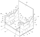
図1乃至図5は、本発明に係る実施形態の包装箱1を示す。この包装箱1は、各一対の端壁10A,10Bおよび側壁11A,11Bを有する平面視四角形状のもので、一体的に形成した第1および第2緩衝部24,33A,33Bを内部に配置することにより、平面視八角形状の収容部2を形成可能としたものである。   1 to 5 show a packaging box 1 according to an embodiment of the present invention. The packaging box 1 has a rectangular shape in plan view having a pair of end walls 10A and 10B and side walls 11A and 11B, and the integrally formed first and second buffer portions 24, 33A and 33B are disposed inside. By doing so, it is possible to form the accommodating portion 2 having an octagonal shape in plan view.

この包装箱1は、表ライナおよび裏ライナの間に波状の中しんを配設した周知の段ボール紙を、周知の紙器打抜装置(図示せず)によって図5に示す連続した一枚のブランクとして打ち抜き、所定部位を糊付けにより貼着して成形される。   This packaging box 1 is a continuous blank shown in FIG. 5 by using a well-known cardboard punching device (not shown), which is a well-known corrugated cardboard having corrugated cores disposed between a front liner and a back liner. And a predetermined part is pasted and pasted.

包装箱1のブランクは、図5に示すように、外周壁を構成する各一対の端壁10A,10Bおよび側壁11A,11Bを備えている。これらは、横方向に交互かつ直線的に連続するように設けられている。本実施形態の端壁10A,10Bおよび側壁11A,11Bは、封緘状態で平面視正方形状をなすように同一の横幅で形成されている。これらのうち、左側端部に位置する側壁11Aの側縁には、右側端部に位置する端壁10Bに貼着するための糊代部12が連設されている。そして、側壁11Aと端壁10Aの境界部分、端壁10Aと側壁11Bの境界部分、側壁11Bと端壁10Bの境界部分、および、糊代部12と側壁11Aの境界部分には、それぞれ肉厚を圧縮するように罫を入れて形成した折曲線13が縦方向に延びるように設けられている。なお、本実施形態の糊代部12には、後述する緩衝フラップ21Bおよび内側底フラップ16Bに貼着するための糊代片14A,14Bが上下に連設され、その境界部分に折曲線15が設けられている。   As shown in FIG. 5, the blank of the packaging box 1 includes a pair of end walls 10A and 10B and side walls 11A and 11B constituting an outer peripheral wall. These are provided so as to be alternately and linearly continuous in the lateral direction. The end walls 10A and 10B and the side walls 11A and 11B of the present embodiment are formed with the same lateral width so as to form a square shape in a plan view in a sealed state. Among these, the margin part 12 for adhering to the end wall 10B located in the right end part is connected to the side edge of the side wall 11A located in the left end part. Further, the boundary part between the side wall 11A and the end wall 10A, the boundary part between the end wall 10A and the side wall 11B, the boundary part between the side wall 11B and the end wall 10B, and the boundary part between the adhesive margin 12 and the side wall 11A are respectively thick. A folding line 13 formed with a ruled line so as to compress is provided so as to extend in the vertical direction. In the glue margin portion 12 of the present embodiment, glue margin pieces 14A and 14B for adhering to a buffer flap 21B and an inner bottom flap 16B described later are provided vertically, and a folding line 15 is formed at the boundary portion. Is provided.

端壁10A,10Bの下端には内側底フラップ16A,16Bが連設され、側壁11A,11Bの下端には外側底フラップ17A,17Bが連設されている。これら底フラップ16A,16B,17A,17Bと各壁10A,10B,11A,11Bとの境界部分には折曲線18が設けられている。底フラップ16A,16B,17A,17Bは、内外に重畳するように折り曲げることにより、端壁10A,10Bおよび側壁11A,11Bで囲まれた底面を閉塞するものである。具体的には、内側底フラップ16A,16Bは、端壁10A,10Bに対して折り曲げられ、その後に外側底フラップ17A,17Bを側壁11A,11Bに対して折り曲げることにより、この外側底フラップ17A,17Bの内側に全体が位置する。また、外側底フラップ17A,17Bは、側壁11A,11Bに対して折り曲げた状態で、互いの先端縁が突き合う寸法で形成されている。   Inner bottom flaps 16A and 16B are connected to the lower ends of the end walls 10A and 10B, and outer bottom flaps 17A and 17B are connected to the lower ends of the side walls 11A and 11B. A folding line 18 is provided at the boundary between the bottom flaps 16A, 16B, 17A, and 17B and the walls 10A, 10B, 11A, and 11B. The bottom flaps 16A, 16B, 17A, and 17B close the bottom surface surrounded by the end walls 10A and 10B and the side walls 11A and 11B by being bent so as to overlap inside and outside. Specifically, the inner bottom flaps 16A and 16B are bent with respect to the end walls 10A and 10B, and then the outer bottom flaps 17A and 17B are bent with respect to the side walls 11A and 11B. The whole is located inside 17B. In addition, the outer bottom flaps 17A and 17B are formed to have a size such that the leading edges of the outer bottom flaps 17A and 17B collide with each other in a state of being bent with respect to the side walls 11A and 11B.

内側底フラップ16A,16Bには、折曲線18の中央に位置するように、矩形状の第1係止溝19が打ち抜きにより設けられている。また、内側底フラップ16A,16Bには、両側中央から折曲線18の略中央に向けて45度の傾斜角度で延びるように、第2係止溝20が打ち抜きにより設けられている。この第2係止溝20において、内側底フラップ16A,16Bの側縁に位置する端部は、円弧状をなすように面取りされている。   The inner bottom flaps 16A and 16B are provided with a rectangular first locking groove 19 by punching so as to be located at the center of the folding line 18. The inner bottom flaps 16A and 16B are provided with a second locking groove 20 by punching so as to extend from the center of both sides toward the approximate center of the folding line 18 at an inclination angle of 45 degrees. In the second locking groove 20, the end portions located on the side edges of the inner bottom flaps 16A and 16B are chamfered so as to form an arc shape.

また、端壁10A,10Bの上端には緩衝フラップ21A,21Bが連設され、側壁11A,11Bの上端には天フラップ22A,22Bが連設されている。そして、これらフラップ21A,21B,22A,22Bと各壁10A,10B,11A,11Bの境界部分には折曲線23が設けられている。そのうち、天フラップ22A,22Bは、対向する側壁11B,11Aまでの寸法より僅かに小さい寸法で形成される。また、天フラップ22A,22Bは、折曲線23の形成位置が異なるように形成されている。具体的には、天フラップ22Aの折曲線23は、天フラップ22Bの折曲線23より先端側に位置するように形成されている。これにより、天フラップ22Bを先に折り曲げた後、天フラップ22Aを折り曲げることにより、端壁10A,10Bおよび側壁11A,11Bで囲まれた天面を閉塞する構成としている。さらに、緩衝フラップ21A,21Bには、中央に第1緩衝部24が設けられ、その両側に第2緩衝部33A,33Bが設けられている。   Further, buffer flaps 21A and 21B are connected to the upper ends of the end walls 10A and 10B, and top flaps 22A and 22B are connected to the upper ends of the side walls 11A and 11B. A folding line 23 is provided at the boundary between these flaps 21A, 21B, 22A, 22B and the walls 10A, 10B, 11A, 11B. Of these, the top flaps 22A and 22B are formed with dimensions slightly smaller than the dimensions of the opposing side walls 11B and 11A. Further, the top flaps 22A and 22B are formed so that the formation positions of the folding lines 23 are different. Specifically, the folding line 23 of the top flap 22A is formed so as to be positioned on the tip side from the folding line 23 of the top flap 22B. Thus, after the top flap 22B is bent first, the top flap 22A is bent to close the top surface surrounded by the end walls 10A, 10B and the side walls 11A, 11B. Further, the buffer flaps 21A and 21B are provided with a first buffer portion 24 at the center and second buffer portions 33A and 33B on both sides thereof.

第1緩衝部24は、端壁10A,10Bに連続した第1上面部25と、この第1上面部25に連続した第1内壁部26と、この第1内壁部26に連続した折返部27と、この折返部27に連続した折込部28とを有する。そのうち、第1内壁部26は、端壁10A,10Bの内面側に平行に折り込まれるもので、その下端縁中央には、内側底フラップ16A,16Bの第1係止溝19に係止される第1係止突部29が設けられている。この第1係止突部29は、第1内壁部26から折込部28にかけて延びる一対の第1切断部30,30と、これら第1切断部30,30の先端間にかけて延びる第2切断部31とで区画されている。そして、第1上面部25と第1内壁部26の境界部分、第1係止突部29の領域を除く第1内壁部26と折返部27の境界部分、および、折返部27と折込部28の境界部分には、平行に延びる折曲線32が設けられている。   The first buffer portion 24 includes a first upper surface portion 25 that is continuous with the end walls 10A and 10B, a first inner wall portion 26 that is continuous with the first upper surface portion 25, and a folded portion 27 that is continuous with the first inner wall portion 26. And a folding part 28 continuous with the folding part 27. Among them, the first inner wall portion 26 is folded in parallel to the inner surface side of the end walls 10A and 10B, and is locked to the first locking groove 19 of the inner bottom flaps 16A and 16B at the center of the lower end edge. A first locking protrusion 29 is provided. The first locking protrusion 29 includes a pair of first cutting portions 30 and 30 extending from the first inner wall portion 26 to the folding portion 28, and a second cutting portion 31 extending between the tips of the first cutting portions 30 and 30. It is divided by and. And the boundary part of the 1st upper surface part 25 and the 1st inner wall part 26, the boundary part of the 1st inner wall part 26 and the folding | returning part 27 except the area | region of the 1st latching protrusion 29, and the folding | returning part 27 and the folding part 28 A folding line 32 extending in parallel is provided at the boundary portion.

第2緩衝部33A,33Bは、端壁10A,10Bに連続した第2上面部34と、この第2上面部34の内縁に連続する第2内壁部35と、この第2内壁部35の側縁に連続する重畳部36とを有する。第2上面部34は、その内縁が隣接する側壁11A,11Bに向けて45度の傾斜角度で延び、側縁が隣接する側壁11A,11Bの内面に沿って延びる直角台形状をなす。第2内壁部35は、下向きに折り込まれる先(下)細の直角台形状のもので、その下端縁が内側底フラップ16A,16Bの第2係止溝20に係止される第2係止突部37を構成する。重畳部36は、側壁11A,11Bに重畳するように折り曲げられるものである。第2上面部34と第2内壁部35の境界部分、および、第2内壁部35と重畳部36の境界部分には、肉厚を圧縮するように罫を入れて設けた折曲部と、この折曲線上に位置する切断部とからなるリード罫38が設けられている。   The second buffer portions 33A and 33B include a second upper surface portion 34 continuous with the end walls 10A and 10B, a second inner wall portion 35 continuous with the inner edge of the second upper surface portion 34, and the second inner wall portion 35 side. And an overlapping portion 36 continuous with the edge. The second upper surface portion 34 has a trapezoidal shape in which the inner edge extends at an inclination angle of 45 degrees toward the adjacent side walls 11A and 11B, and the side edge extends along the inner surface of the adjacent side walls 11A and 11B. The second inner wall portion 35 has a narrow (right) trapezoidal trapezoidal shape that is folded downward, and the lower end edge of the second inner wall portion 35 is engaged with the second engagement groove 20 of the inner bottom flaps 16A and 16B. A protrusion 37 is formed. The overlapping part 36 is bent so as to overlap the side walls 11A and 11B. A bent portion provided with a ruled line so as to compress the thickness at a boundary portion between the second upper surface portion 34 and the second inner wall portion 35 and a boundary portion between the second inner wall portion 35 and the overlapping portion 36; A lead ruler 38 made of a cutting part located on the folding line is provided.

このように打ち抜かれた包装箱1のブランクは、端壁10Aに対して側壁11Aを折り曲げるとともに、側壁11Bに対して端壁10Bを折り曲げ、重畳する糊代部12と端壁10Bとを、酢酸ビニルエマルジョン系などの接着剤により糊付けする。そして、この折畳状態で所定の製造メーカ等に納品される。   The blank of the packaging box 1 punched out in this way bends the side wall 11A with respect to the end wall 10A, bends the end wall 10B with respect to the side wall 11B, and combines the overlapping margin portion 12 and the end wall 10B with acetic acid. Glue with an adhesive such as vinyl emulsion. Then, it is delivered to a predetermined manufacturer or the like in this folded state.

この包装箱1に商品を収容する場合には、図1に示すように、まず、各端壁10A,10Bおよび側壁11A,11Bを四角形状をなすように広げる。その後、端壁10A,10Bに対して内側底フラップ16A,16Bを折り曲げた後、側壁11A,11Bに対して外側底フラップ17A,17Bを折り曲げる。そして、互いに突き合った外側底フラップ17A,17Bの先端を粘着テープなどの固着手段によって固着する。   When a product is stored in the packaging box 1, as shown in FIG. 1, first, the end walls 10A and 10B and the side walls 11A and 11B are expanded so as to form a square shape. Thereafter, the inner bottom flaps 16A and 16B are bent with respect to the end walls 10A and 10B, and then the outer bottom flaps 17A and 17B are bent with respect to the side walls 11A and 11B. Then, the tips of the outer bottom flaps 17A and 17B that face each other are fixed by a fixing means such as an adhesive tape.

ついで、図2に示すように、第1緩衝部24を構成する折込部28、折返部27、第1内壁部26および第1上面部25をそれぞれ折曲線23,32に沿って折り曲げ、第1内壁部26に対して面一に突出する第1係止突部29を内側底フラップ16A,16Bの第1係止溝19に挿入して係止させる。   Next, as shown in FIG. 2, the folding portion 28, the folding portion 27, the first inner wall portion 26, and the first upper surface portion 25 constituting the first buffer portion 24 are bent along folding lines 23 and 32, respectively. A first locking projection 29 protruding flush with the inner wall portion 26 is inserted into the first locking groove 19 of the inner bottom flaps 16A, 16B and locked.

ついで、図3に示すように、第2緩衝部33A,33Bを構成する第2上面部34を端壁10A,10Bに対して折り曲げた後、図4に示すように、第2上面部34に対して第2内壁部35を折り曲げるとともに、第2内壁部35に対して重畳部36を折り曲げる。そして、第2内壁部35の下端である第2係止突部37を内側底フラップ16A,16Bの第2係止溝20に挿入して係止させる。   Next, as shown in FIG. 3, after the second upper surface portion 34 constituting the second buffer portions 33A and 33B is bent with respect to the end walls 10A and 10B, the second upper surface portion 34 is formed on the second upper surface portion 34 as shown in FIG. On the other hand, the second inner wall portion 35 is bent, and the overlapping portion 36 is bent with respect to the second inner wall portion 35. And the 2nd latching protrusion 37 which is a lower end of the 2nd inner wall part 35 is inserted in the 2nd latching groove 20 of inner side bottom flap 16A, 16B, and is latched.

これにより図4に示すように、包装箱1の内部に、側壁11A,11Bと2個の第1緩衝部24と4個の第2緩衝部33A,33Bで囲まれた平面視八角形状の収容部2が形成される。即ち、一体に形成された1枚のブランクを折り曲げることにより、平面視多角形状をなす収容部2を形成することができる。そして、この包装箱1に商品を収容させる際には、上方から内部に配置させるだけで良いため、収容作業性は良好である。   As a result, as shown in FIG. 4, an octagonal storage in a plan view surrounded by the side walls 11 </ b> A and 11 </ b> B, the two first buffer parts 24 and the four second buffer parts 33 </ b> A and 33 </ b> B is provided inside the packaging box 1. Part 2 is formed. That is, it is possible to form the accommodating portion 2 having a polygonal shape in plan view by bending one integrally formed blank. And when accommodating goods in this packaging box 1, since it only has to arrange | position inside from upper direction, accommodation workability | operativity is favorable.

そして、収容部2に商品を収容すると、側壁11Bに対して天フラップ22Bを折り曲げた後、側壁11Aに対して天フラップ22Aを折り曲げる。そして、この天フラップ22Aの先端と、天フラップ22Bの根元部分または側壁11Bにかけて粘着テープなどの固着手段によって固着する。   And if a goods are accommodated in the accommodating part 2, after bending the top flap 22B with respect to the side wall 11B, the top flap 22A will be bent with respect to the side wall 11A. And it adheres to the front-end | tip of this top flap 22A, the base part of the top flap 22B, or the side wall 11B with adhesion | attachment means, such as an adhesive tape.

このようにして封緘した包装箱1は、底面を閉塞する底フラップ16A,16B,17A,17Bのうち、内側に位置する内側底フラップ16A,16Bに各緩衝部24,33A,33Bの係止突部29,37を係止する係止溝19.20を設けている。そして、その係止溝19,20は、外側に位置する外側底フラップ17A,17Bによって閉塞される。そのため、係止溝19,20によって外観が損なわれることはないうえ、塵埃が内部に侵入することを確実に防止できる。   The packaging box 1 sealed in this way has the locking projections of the buffer portions 24, 33A, 33B on the inner bottom flaps 16A, 16B located on the inner side among the bottom flaps 16A, 16B, 17A, 17B closing the bottom surface. A locking groove 19.20 for locking the portions 29 and 37 is provided. The locking grooves 19 and 20 are closed by outer bottom flaps 17A and 17B located outside. Therefore, the external appearance is not impaired by the locking grooves 19 and 20, and dust can be reliably prevented from entering the inside.

なお、本発明の包装箱1は、前記実施形態の構成に限定されるものではなく、種々の変更が可能である。   In addition, the packaging box 1 of this invention is not limited to the structure of the said embodiment, A various change is possible.

例えば、前記実施形態では、第1緩衝部24の両側に一対の第2緩衝部33A,33Bを設けたが、第1緩衝部24を端壁10A,10Bの半分の領域に連設し、他の半分の領域に1個の第2緩衝部33を設けることにより、平面視六角形状の収容部2を設ける構成としてもよい。また、包装箱1は、天フラップ22A,22Bを設けないトレー状としてもよい。さらに、包装箱1は平面視正方形状に限られず、長方形状としてもよい。   For example, in the above-described embodiment, the pair of second buffer parts 33A and 33B are provided on both sides of the first buffer part 24. However, the first buffer part 24 is connected to the half region of the end walls 10A and 10B, and the like. It is good also as a structure which provides the accommodating part 2 of planar view hexagonal shape by providing the 1st 2nd buffer part 33 in the area | region of a half. Moreover, the packaging box 1 is good also as a tray shape which does not provide the top flaps 22A and 22B. Furthermore, the packaging box 1 is not limited to a square shape in plan view, and may be a rectangular shape.

また、前記実施形態では、底フラップは、内側に位置する内側底フラップ16A,16Bと、外側に位置する外側底フラップ17A,17Bにより構成したが、内外に重畳された状態で底面を閉塞するものであればよい。即ち、4面の底フラップ16A,16B,17A,17Bのうち、第1の底フラップ16Aを折り畳んだ後、隣接する第2の底フラップ17A、第3の底フラップ16B、そして、第4の底フラップ17Bを順番に折り曲げ、最後の第4の底フラップ17Bの半分の領域を第1の底フラップ16Aの内側に折り込むようにする、所謂風車ロック方式としてもよい。また、側壁11Aを端壁10Aに対して折り曲げ、端壁10Bを側壁11Bに対して折り曲げた重畳状態で、底フラップ16A,16Bの一部を重畳する底フラップ17A,17Bに貼着しておき、端壁10A,10Bおよび側壁11A,11Bを矩形状をなすように広げることにより、自動的に底フラップ16A,16B,17A,17Bが閉塞するようにした所謂底ワンタッチ封緘方式としてもよい。そして、これらにおいても、底フラップ16A,16B,17A,17Bの内側に位置する部分に係止溝19,20を設けることにより、前記実施形態と同様の作用および効果を得ることができる。   Moreover, in the said embodiment, although the bottom flap was comprised by inner bottom flap 16A, 16B located inside, and outer bottom flap 17A, 17B located outside, what closes a bottom face in the state overlapped inside and outside If it is. That is, after folding the first bottom flap 16A among the four bottom flaps 16A, 16B, 17A, and 17B, the adjacent second bottom flap 17A, third bottom flap 16B, and fourth bottom A so-called windmill locking method may be employed in which the flaps 17B are bent in order, and the half region of the last fourth bottom flap 17B is folded inside the first bottom flap 16A. Further, in a superposed state where the side wall 11A is bent with respect to the end wall 10A and the end wall 10B is bent with respect to the side wall 11B, a part of the bottom flaps 16A and 16B is stuck on the bottom flaps 17A and 17B. The so-called bottom one-touch sealing method may be adopted in which the end flaps 10A, 10B and the side walls 11A, 11B are expanded so as to form a rectangular shape so that the bottom flaps 16A, 16B, 17A, 17B are automatically closed. And also in these, the effect | action and effect similar to the said embodiment can be acquired by providing the latching grooves 19 and 20 in the part located inside bottom flap 16A, 16B, 17A, 17B.

さらに、前記実施形態では、第2上面部34は、その内縁が隣接する側壁11A,11Bに向けて45度の傾斜角度で延びるように設けたが、その傾斜角度は希望に応じて変更が可能である。この場合、第2上面部34の内縁に沿って下向きに延びる第2内壁部35の係止突部37と一致するように、内側底フラップ16A,16Bに形成する第2係止溝20の傾斜角度も同様に変更する。   Furthermore, in the said embodiment, although the 2nd upper surface part 34 was provided so that the inner edge might be extended with the inclination angle of 45 degree | times toward the adjacent side walls 11A and 11B, the inclination angle can be changed as desired. It is. In this case, the inclination of the second locking groove 20 formed in the inner bottom flaps 16A and 16B so as to coincide with the locking protrusion 37 of the second inner wall portion 35 extending downward along the inner edge of the second upper surface portion 34. Change the angle as well.

さらにまた、前記実施形態では、内側底フラップ16A,16Bに形成する第2係止溝20を、内側底フラップ16A,16Bの両側縁から延びるスリット状に形成したが、側縁から所定間隔をもって位置する中抜きの打抜溝により構成してもよい。この場合、第2内壁部35に形成する係止突部37も同様に、第2内壁部35の所定位置からのみ突出するように形成する。   Furthermore, in the embodiment, the second locking groove 20 formed in the inner bottom flaps 16A and 16B is formed in a slit shape extending from both side edges of the inner bottom flaps 16A and 16B. You may comprise by the hollow punching groove | channel which carries out. In this case, the locking projection 37 formed on the second inner wall 35 is similarly formed so as to protrude only from a predetermined position of the second inner wall 35.

1…包装箱
2…収容部
10A,10B…端壁
11A,11B…側壁
16A,16B…内側底フラップ
17A,17B…外側底フラップ
19…第1係止溝
20…第2係止溝
21A,21B…緩衝フラップ
24…第1緩衝部
25…第1上面部
26…第1内壁部
27…折返部
28…折込部
29…第1係止突部
33A,33B…第2緩衝部
34…第2上面部
35…第2内壁部
36…重畳部
37…第2係止突部
DESCRIPTION OF SYMBOLS 1 ... Packaging box 2 ... Storage part 10A, 10B ... End wall 11A, 11B ... Side wall 16A, 16B ... Inner bottom flap 17A, 17B ... Outer bottom flap 19 ... First locking groove 20 ... Second locking groove 21A, 21B ... Buffer flap 24 ... First buffer part 25 ... First upper surface part 26 ... First inner wall part 27 ... Folded part 28 ... Folding part 29 ... First locking projections 33A, 33B ... Second buffer part 34 ... Second upper surface Part 35 ... Second inner wall part 36 ... Overlapping part 37 ... Second locking protrusion

Claims (1)

横方向に交互に連続する各一対の端壁および側壁を有する平面視四角形状をなし、これら端壁および側壁の下端に内外に重畳した状態で底面を閉塞する底フラップを連設した包装箱において、
前記各端壁の上端に、各端壁の内面側に略平行に折り込まれる第1内壁部を有する第1緩衝部を連設するとともに、隣接する前記側壁に向けて延びる上面部およびこの上面部の内縁から下向きに折り込まれる第2内壁部を有する第2緩衝部を連設し、
前記第1および第2内壁部の下端縁に係止突部を設け、前記底フラップの内側に位置する部分に、前記係止突部を係止する係止溝を設けた
ことを特徴とする包装箱。
In a packaging box having a rectangular shape in a plan view having a pair of end walls and side walls alternately arranged in the lateral direction, and having bottom flaps continuously closing the end walls and the lower ends of the side walls in a state of being overlapped inside and outside ,
A first buffer portion having a first inner wall portion that is folded substantially parallel to the inner surface side of each end wall is provided at the upper end of each end wall, and an upper surface portion that extends toward the adjacent side wall and the upper surface portion. A second buffer portion having a second inner wall portion that is folded downward from the inner edge of the
A locking projection is provided at the lower end edge of the first and second inner wall portions, and a locking groove for locking the locking projection is provided in a portion located inside the bottom flap. Packaging box.
JP2011129382A 2011-06-09 2011-06-09 Packaging box Withdrawn JP2012254815A (en)

Priority Applications (1)

Application Number Priority Date Filing Date Title
JP2011129382A JP2012254815A (en) 2011-06-09 2011-06-09 Packaging box

Applications Claiming Priority (1)

Application Number Priority Date Filing Date Title
JP2011129382A JP2012254815A (en) 2011-06-09 2011-06-09 Packaging box

Publications (1)

Publication Number Publication Date
JP2012254815A true JP2012254815A (en) 2012-12-27

Family

ID=47526793

Family Applications (1)

Application Number Title Priority Date Filing Date
JP2011129382A Withdrawn JP2012254815A (en) 2011-06-09 2011-06-09 Packaging box

Country Status (1)

Country Link
JP (1) JP2012254815A (en)

Cited By (2)

* Cited by examiner, † Cited by third party
Publication number Priority date Publication date Assignee Title
KR101840937B1 (en) 2016-07-27 2018-03-21 주식회사 삼보테크 Packing box for spectacle lens
JP2021004067A (en) * 2019-06-26 2021-01-14 レンゴー株式会社 Packing box

Cited By (3)

* Cited by examiner, † Cited by third party
Publication number Priority date Publication date Assignee Title
KR101840937B1 (en) 2016-07-27 2018-03-21 주식회사 삼보테크 Packing box for spectacle lens
JP2021004067A (en) * 2019-06-26 2021-01-14 レンゴー株式会社 Packing box
JP7220956B2 (en) 2019-06-26 2023-02-13 レンゴー株式会社 packaging box

Similar Documents

Publication Publication Date Title
JP2009067449A (en) Packaging box
JP2012254815A (en) Packaging box
JP6413928B2 (en) tray
JP5917224B2 (en) Packaging box
JP2008081175A (en) Packaging box
JP5749602B2 (en) Packaging box
JP2017507857A (en) Cardboard sheet material trays for manual assembly and blanks for making such trays
JP6433381B2 (en) Exterior display box
JP2021095183A (en) Packaging box with partition
JP2007182249A (en) Lidded carton
JP6549391B2 (en) Storage box
JP2013163537A (en) Packaging box
JP6919532B2 (en) Flower packaging box
JP2019064719A (en) Packaging box
JP2008030834A (en) Corrugated cardboard case
JP3239036U (en) box sheet
JP7113616B2 (en) packaging box
JP6907074B2 (en) Packaging box
JP7319814B2 (en) packaging box
TWM528967U (en) Paper box structure
JP2016068984A (en) Packing box
JP3162999U (en) Stackable packaging box
JP3204901U (en) Pack suspended packaging box and its partition plate
JP2023084961A (en) packaging box
JP4490204B2 (en) Packaging box components

Legal Events

Date Code Title Description
A300 Withdrawal of application because of no request for examination

Free format text: JAPANESE INTERMEDIATE CODE: A300

Effective date: 20140902