JP2012253680A - Offload handover method, radio base station and gateway device - Google Patents
Offload handover method, radio base station and gateway device Download PDFInfo
- Publication number
- JP2012253680A JP2012253680A JP2011126565A JP2011126565A JP2012253680A JP 2012253680 A JP2012253680 A JP 2012253680A JP 2011126565 A JP2011126565 A JP 2011126565A JP 2011126565 A JP2011126565 A JP 2011126565A JP 2012253680 A JP2012253680 A JP 2012253680A
- Authority
- JP
- Japan
- Prior art keywords
- base station
- address
- handover
- radio base
- destination
- Prior art date
- Legal status (The legal status is an assumption and is not a legal conclusion. Google has not performed a legal analysis and makes no representation as to the accuracy of the status listed.)
- Withdrawn
Links
Images


Abstract
Description
本発明は、オフロード通信を行う移動体無線通信システムにおけるオフロードハンドオーバ方法に関する。 The present invention relates to an offload handover method in a mobile radio communication system that performs offload communication.
近年の移動体通信システムでは、下記非特許文献1に示されるように、無線端末が移動体コアネットワークを経由せずに、小型無線基地局を経由して直接インターネット内のサーバと通信を実施するオフロード通信が検討されている。また、下記特許文献1では、移動体コアネットワークを経由する接続状態において、無線端末と前記インターネット内のサーバ間のトラヒック量をモニタし、所定の条件を満たした場合にコアネットワークを経由しない接続状態に切り替える技術が開示されている。
In recent mobile communication systems, as shown in Non-Patent
しかしながら、上記従来の技術によれば、オフロード状態の無線端末は、無線基地局が取得したインターネット接続用のIPアドレスを使用してインターネット上のサーバと通信を行う。そのため、無線端末が移動して別の無線基地局に接続するハンドオーバを行った場合、IPアドレスを変更することになりインターネット上のサーバとの通信を継続できない、という問題があった。 However, according to the above conventional technique, the wireless terminal in the offload state communicates with a server on the Internet using the IP address for Internet connection acquired by the wireless base station. Therefore, when a wireless terminal moves and performs a handover to connect to another wireless base station, there is a problem that an IP address is changed and communication with a server on the Internet cannot be continued.
本発明は、上記に鑑みてなされたものであって、オフロード通信をしている無線端末がオフロード通信を継続したままハンドオーバをすることが可能なオフロードハンドオーバ方法を得ることを目的とする。 The present invention has been made in view of the above, and an object of the present invention is to provide an offload handover method in which a wireless terminal performing offload communication can perform handover while continuing offload communication. .
上述した課題を解決し、目的を達成するために、本発明は、無線端末が、無線基地局を介して、移動体コアネットワークを経由せずに公衆アクセスネットワークを経由してインターネット上の装置とオフロード通信を行う移動体通信システムにおけるオフロードハンドオーバ方法であって、ハンドオーバ元無線基地局が、ハンドオーバ先無線基地局に対して、自局における無線端末用アドレスである第1のアドレスの情報を通知する第1のアドレス通知ステップと、ハンドオーバ先無線基地局が、前記ハンドオーバ元無線基地局に対して、自局における無線端末用アドレスである第2のアドレスの情報を通知する第2のアドレス通知ステップと、ハンドオーバ元無線基地局が、前記インターネット上の装置から受信した前記無線端末あてのパケットの送信先アドレスを前記第1のアドレスから前記第2のアドレスに変換し、当該パケットを前記公衆アクセスネットワーク経由で前記ハンドオーバ先無線基地局に転送するハンドオーバ元無線基地局転送ステップと、ハンドオーバ先無線基地局が、受信した前記パケットの送信先アドレスを前記第2のアドレスから前記第1のアドレスに変換し、当該パケットを前記無線端末に送信するハンドオーバ先無線基地局送信ステップと、を含むことにより、オフロード通信を継続したままハンドオーバを実施することを特徴とする。 In order to solve the above-described problems and achieve the object, the present invention provides a wireless terminal connected to a device on the Internet via a wireless base station and not via a mobile core network but via a public access network. An offload handover method in a mobile communication system that performs offload communication, in which a handover source radio base station sends information on a first address that is an address for a radio terminal in its own station to a handover destination radio base station A first address notification step of notifying, and a second address notification in which the handover destination radio base station notifies the handover source radio base station of information of a second address which is a radio terminal address in the own station And a handover source wireless base station to the wireless terminal received from the device on the Internet. A handover source radio base station transfer step of converting a packet transmission destination address from the first address to the second address and transferring the packet to the handover destination radio base station via the public access network; A destination radio base station that converts a destination address of the received packet from the second address to the first address, and transmits the packet to the radio terminal. Thus, the handover is performed while the offload communication is continued.
本発明によれば、オフロード通信をしている無線端末がオフロード通信を継続したままハンドオーバをすることができる、という効果を奏する。 Advantageous Effects of Invention According to the present invention, there is an effect that a wireless terminal performing offload communication can perform handover while continuing offload communication.
以下に、本発明にかかるオフロードハンドオーバ方法の実施の形態を図面に基づいて詳細に説明する。なお、この実施の形態によりこの発明が限定されるものではない。 Embodiments of an offload handover method according to the present invention will be described below in detail with reference to the drawings. Note that the present invention is not limited to the embodiments.
実施の形態1.
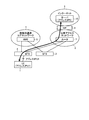
図1は、本実施の形態の移動体通信システムの構成例を示す図である。移動体通信システムは、無線端末(以下、UEとする。)1と、無線基地局(以下、BTSとする。)2、3と、移動体通信コアネットワーク4と、移動体通信コアネットワーク4内にある移動管理装置(以下、MMEとする。)5と、公衆アクセスネットワーク6と、公衆アクセスネットワーク6内にあるルータ7と、ゲートウェイ装置(以下、GWとする。)8と、インターネット9と、インターネット9上にあるサーバ10と、から構成される。
FIG. 1 is a diagram showing a configuration example of a mobile communication system according to the present embodiment. The mobile communication system includes a radio terminal (hereinafter referred to as UE) 1, a radio base station (hereinafter referred to as BTS) 2 and 3, a mobile communication core network 4, and a mobile communication core network 4. Mobile management device (hereinafter referred to as MME) 5,
UE1は、BTS2、3と無線により接続可能な端末である。BTS2、3は、UE1と接続し、移動体通信コアネットワーク4または公衆アクセスネットワーク6との通信を中継する。移動体通信コアネットワーク4は、移動体通信を提供するネットワークである。MME5は、UE1の移動や通信呼を管理する。ルータ7は、公衆アクセスネットワーク6内でパケットのルーティングを行い、BTS2、3と接続する。GW8は、公衆アクセスネットワーク6とインターネット9を接続する。サーバ10は、インターネット9上にあり、各種サービスを提供する。ここでは、サーバ10のIPアドレスを「IPS」とする。
The UE 1 is a terminal that can be connected to the
図1において、UE1は、BTS2と接続しており、BTS2に割り当てられた無線端末用(UE)アドレス「IPU1」を使用し、移動体通信コアネットワーク4を経由せずに、BTS2および公衆アクセスネットワーク6を経由してインターネット9上のサーバ10とオフロード通信を行っている。UEアドレスを取得する方法としては、例えば、DHCP(Dynamic Host Configuration Protocol)を利用する方法や、事前に決定しておくなど種々の方法があり、いずれかの方法に限定するものではない。なお、UEアドレス「IPU1」を第1のアドレスとする。
In FIG. 1, UE1 is connected to BTS2, uses a radio terminal (UE) address “IPU1” assigned to BTS2, and does not go through mobile communication core network 4, but BTS2 and
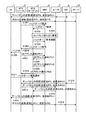
つづいて、UE1がオフロード通信を行っている状態からハンドオーバを行う動作について説明する。図2は、本実施の形態の移動体通信システムにおけるハンドオーバ動作を示すシーケンス図である。 Next, an operation for performing handover from a state in which UE1 is performing offload communication will be described. FIG. 2 is a sequence diagram showing a handover operation in the mobile communication system according to the present embodiment.
ここで、ハンドオーバ実施前の状態では、サーバ10がUE1に対して送信するパケットの送信元アドレスは「IPS」、送信先アドレスは「IPU1」である。当該パケットは、送信先アドレス「IPU1」によって、インターネット9内、GW8、ルータ7、BTS2とルーティングされてUE1に到着する。また、UE1がサーバ10に対して送信するパケットの送信元アドレスは「IPU1」、送信先アドレスは「IPS」である。当該パケットは、送信先アドレス「IPS」によって、BTS2、ルータ7、GW8とルーティングされ、さらにインターネット9内をルーティングされてサーバ10に到着する。UE1とサーバ10は、パケットのアドレスによって通信相手を特定して通信を行っている。
Here, in a state before the handover is performed, the transmission source address of the packet transmitted from the
この状態から、BTS2をハンドオーバ元(ソース無線基地局)、BTS3をハンドオーバ先(ターゲット無線基地局)とするハンドオーバを実施する場合について説明する。まず、BTS2が、MME5に対してハンドオーバ要求を送信する(ステップS1001)。ハンドオーバ要求を受信したMME5は、ハンドオーバ要求をターゲットであるBTS3に送信する(ステップS1002)。BTS3は、受信したハンドオーバ要求に基づいて、UE1のためのUEアドレスを取得する処理(割り当て処理)を実施し、UEアドレス「IPU2」を取得する(ステップS1003)。UEアドレス「IPU2」を第2のアドレスとする。また、BTS3は、ハンドオーバ実施を承認するハンドオーバ要求確認をMME5に対して送信する(ステップS1004)。
From this state, a case will be described in which handover is performed with BTS2 as the handover source (source radio base station) and BTS3 as the handover destination (target radio base station). First, the BTS 2 transmits a handover request to the MME 5 (step S1001). The
MME5は、ハンドオーバの実施を通知するため、BTS2に対してハンドオーバ命令を送信する(ステップS1005)。ハンドオーバ命令を受信したBTS2は、UE1に対してハンドオーバ命令を送信する(ステップS1006)。
The
BTS2は、UE1が使用していたUEアドレス「IPU1」をBTS3に通知するため、UEアドレス通知をMME5に送信する(ステップS1007)。UEアドレス通知を受信したMME5は、BTS3にUEアドレス通知を送信する(ステップS1008)。また、BTS3は、UE1のために取得したUEアドレス「IPU2」をBTS2に通知するため、UEアドレス通知をMME5に送信する(ステップS1009)。UEアドレス通知を受信したMME5は、BTS2にUEアドレス通知を送信する(ステップS1010)。
The BTS 2 transmits a UE address notification to the
一方、ステップS1006でハンドオーバ命令を受信したUE1は、接続先をBTS3に変更して、ハンドオーバ実施通知をBTS3に送信する(ステップS1011)。これにより、BTS3は、UE1がハンドオーバを実施して自局に接続したことを認識する。 On the other hand, UE1 that has received the handover command in step S1006 changes the connection destination to BTS3 and transmits a handover execution notification to BTS3 (step S1011). As a result, the BTS 3 recognizes that the UE 1 has performed handover and has connected to its own station.
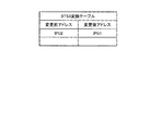
図3は、ハンドオーバによりBTS2に生成されるアドレス変換テーブルを示す図である。BTS2では、「IPU1」を「IPU2」に変換する。また、図4は、ハンドオーバによりBTS3に生成されるアドレス変換テーブルを示す図である。BTS3では、「IPU2」を「IPU1」に変換する。
FIG. 3 is a diagram illustrating an address conversion table generated in the
図2に示すハンドオーバを実施後、サーバ10が、送信元アドレス「IPS」、送信先アドレス「IPU1」としてUE1へパケットを送信すると、インターネット9内、GW8、ルータ7をルーティングされてハンドオーバ前のBTS2にパケットが送信される(ステップS1012)。BTS2は、送信先アドレス「IPU1」を「IPU2」に変換して、ルータ7へパケットを送信する(ステップS1013)。ルータ7は、送信先アドレス「IPU2」に基づいてルーティングを行い、BTS3へパケットを送信する(ステップS1014)。これを受信したBTS3は、送信先アドレスを「IPU2」から「IPU1」に変換して、UE1へパケットを送信する(ステップS1015)。
After the handover shown in FIG. 2 is performed, when the
一方、UE1が、送信元アドレス「IPU1」、送信先アドレス「IPS」としてサーバ10へパケットを送信すると、BTS3、ルータ7、GW8とルーティングされ、さらにインターネット9内をルーティングされてサーバ10にパケットが送信される(ステップS1016)。
On the other hand, when the
以上説明したように、本実施の形態では、オフロード通信中の無線端末がハンドオーバを実施する場合において、ハンドオーバ先の無線基地局は、ハンドオーバ元の無線基地局へ自局で使用する無線端末用アドレスを通知し、ハンドオーバ元の無線基地局は、ハンドオーバ先の無線基地局へ自局で使用していた無線端末用アドレスを通知する。そして、ハンドオーバ元の無線基地局は、ハンドオーバ元の無線端末用アドレスを送信先アドレスにもつパケットについて、送信先アドレスをハンドオーバ先の無線基地局での無線端末用アドレスに変換して公衆アクセスネットワークに送信し、一方、ハンドオーバ先の無線基地局は、ハンドオーバ先の無線基地局での無線端末用アドレスを送信先アドレスにもつパケットについて、送信先アドレスをハンドオーバ前に使用していた無線端末用アドレスに変換して無線端末に送信することとした。これにより、無線端末とインターネット上のサーバでは、ハンドオーバ前とハンドオーバ後で同じ無線端末用アドレスを用いることができ、無線端末は、オフロード通信を継続したまま無線基地局を移動するハンドオーバを実施することができる。 As described above, in the present embodiment, when a radio terminal in offload communication performs a handover, the handover destination radio base station uses the radio terminal for the radio terminal used by itself to the handover source radio base station. The address is notified, and the handover source radio base station notifies the handover destination radio base station of the address for the radio terminal used by itself. Then, the handover source radio base station converts the transmission destination address to the radio terminal address in the handover destination radio base station for the packet having the handover source radio terminal address as the transmission destination address, and converts it into the public access network. On the other hand, for the packet having the wireless terminal address at the handover destination wireless base station as the transmission destination address, the handover destination wireless base station sets the transmission destination address to the wireless terminal address used before the handover. The data is converted and transmitted to the wireless terminal. As a result, the wireless terminal and the server on the Internet can use the same wireless terminal address before and after the handover, and the wireless terminal performs handover for moving the wireless base station while continuing offload communication. be able to.
実施の形態2.
実施の形態1では、ハンドオーバ元の無線基地局とハンドオーバ先の無線基地局で無線端末用アドレスを変換していた。本実施の形態では、ハンドオーバ元の無線基地局における無線端末用アドレスと、ハンドオーバ先の無線基地局における無線端末用アドレスが同一サブネットワークに属する場合に、無線端末がオフロード通信を継続したまま無線基地局を移動するハンドオーバをする方法について説明する。実施の形態1と異なる部分について説明する。
In
図5は、本実施の形態の移動体通信システムの構成例を示す図である。各構成は実施の形態1(図1参照)と同一であるが、ここでは、BTS2、3が同一サブネットワークに属している。
FIG. 5 is a diagram illustrating a configuration example of the mobile communication system according to the present embodiment. Each configuration is the same as in the first embodiment (see FIG. 1), but here,
つづいて、UE1がオフロード通信を行っている状態からハンドオーバを行う動作について説明する。図6は、移動体通信システムにおけるハンドオーバ動作を示すシーケンス図である。 Next, an operation for performing handover from a state in which UE1 is performing offload communication will be described. FIG. 6 is a sequence diagram showing a handover operation in the mobile communication system.
ハンドオーバ実施前の状態は、実施の形態1と同一である。また、BTS2がMME5に対してハンドオーバ要求を送信(ステップS1001)してから、MME5がBTS3にUEアドレス通知を送信(ステップS1008)するまでの動作は実施の形態1と同様である。
The state before the handover is performed is the same as in the first embodiment. The operation from when the
つぎに、BTS3は、MME5から受信したUEアドレス通知で示されるハンドオーバ前のBTS2におけるUE1のUEアドレス「IPU1」と、自局がルータ7から取得したUEアドレス「IPU2」とを比較する。そして、比較した結果、「IPU1」と「IPU2」が同一サブネットに属することを検出する(ステップS2001)。
Next, the
BTS2が取得していたUEアドレスと、BTS3が取得したUEアドレスが同一サブネットに属しているので、サーバ10がパケットを送信すると、そのパケットは、宛先アドレスが「IPU1」であっても「IPU2」であっても同様にインターネット9から公衆アクセスネットワーク6をルーティングされて、BTS2、3を収容するルータ7に到着する。
Since the UE address acquired by BTS2 and the UE address acquired by BTS3 belong to the same subnet, when the
BTS3は、ルータ7に対して「IPU1」の送信先をBTS3に変更する処理を実施する(ステップS2002)。送信先を変更する方法としては、例えば、公衆アクセスネットワーク6とBTS2、3の接続がイーサネット(登録商標)である場合には、GARP(Gratuitous ARP)の送信によりUEアドレス「IPU2」に対応するMACアドレスをルータ7に学習させる方法などがあるが、これに限定するものではない。
The
その後は実施の形態1と同様、ステップS1006でハンドオーバ命令を受信したUE1は、接続先をBTS3に変更して、ハンドオーバ実施通知をBTS3に送信する(ステップS1011)。これにより、BTS3は、UE1がハンドオーバを実施して自局に接続したことを認識する。
Thereafter, as in the first embodiment, UE1 that has received the handover command in step S1006 changes the connection destination to BTS3 and transmits a handover execution notification to BTS3 (step S1011). As a result, the
図6に示すハンドオーバを実施後、サーバ10が、送信元アドレス「IPS」、送信先アドレス「IPU1」としてUE1へパケットを送信すると、当該パケットは、インターネット9から公衆アクセスネットワーク6をルーティングされルータ7に到着する。ルータ7は、「IPU1」の送信先がBTS3となっているので、このパケットをBTS3に送信し、BTS3は、これをUE1に送信する(ステップS2003)。
After the handover shown in FIG. 6 is performed, when the
一方、UE1が、送信元アドレス「IPU1」、送信先アドレス「IPS」としてサーバ10へパケットを送信すると、BTS3、ルータ7、GW8とルーティングされ、さらにインターネット9内をルーティングされてサーバ10にパケットが送信される(ステップS2004)。
On the other hand, when the
以上説明したように、本実施の形態では、オフロード通信中の無線端末がハンドオーバを実施する場合において、ハンドオーバ元の無線基地局は、ハンドオーバ先の無線基地局へ自局で使用していた無線端末用アドレスを通知する。そして、ハンドオーバ先の無線基地局は、自局が取得した無線端末用アドレスとハンドオーバ元の無線基地局が使用していた無線端末用アドレスとを比較し、比較した結果、両アドレスが同一サブネットに属する場合は、ルータに対して、ハンドオーバ元の無線端末用アドレスあてのパケットの送信先をハンドオーバ先の無線基地局へ変更させることとした。これにより、無線端末とインターネット上のサーバでは、ハンドオーバ前とハンドオーバ後で同じ無線端末用アドレスを用いることができ、オフロード通信を継続したまま無線基地局を移動するハンドオーバを実施することができる。また、ハンドオーバ後、サーバから無線端末へパケットを送信するときの動作を、実施の形態1と比較して簡略化することができる。 As described above, in the present embodiment, when a radio terminal in off-road communication performs a handover, the radio base station that is the handover source uses the radio that was used by the local station to the radio base station that is the handover destination. Notify the terminal address. Then, the handover destination radio base station compares the address for the radio terminal acquired by the own station with the address for the radio terminal used by the radio base station of the handover source, and as a result of comparison, both addresses are in the same subnet. In the case of belonging, the router is caused to change the transmission destination of the packet addressed to the handover source wireless terminal address to the handover destination wireless base station. As a result, the wireless terminal and the server on the Internet can use the same wireless terminal address before and after the handover, and the handover for moving the wireless base station can be performed while the offload communication is continued. Further, the operation when transmitting a packet from the server to the wireless terminal after the handover can be simplified as compared with the first embodiment.
実施の形態3.
実施の形態1、2では、公衆アクセスネットワーク6内を、UE1に割り当てられた無線端末用アドレスでルーティングしていた。本実施の形態では、無線基地局2、3とゲートウェイ装置8間にトンネルを構成し、公衆アクセスネットワーク6内をトンネルでパケット転送する場合に、無線端末がオフロード通信を継続したまま無線基地局を移動するハンドオーバをする方法について説明する。実施の形態1、2と異なる部分について説明する。
In the first and second embodiments, routing in the
図7は、本実施の形態のハンドオーバ前の移動体通信システムの構成例を示す図である。ここでは、公衆アクセスネットワーク6にルータ7はなく、BTS2およびGW8は、公衆アクセスネットワーク6間をパケット伝送するためのトンネル101を構成する機能を備える。トンネルを構成する技術としては、例えば、PPP(Point to Point Protocol)やIPsec(Security Architecture for Internet Protocol)トンネルなど種々の技術がある。図7においてトンネル101は、BTS2とGW8間に設定されたトンネルを示している。サーバ10とUE1間の通信データは、インターネット9内をサーバ10もしくはUE1に割り当てられたアドレスでルーティングされ、公衆アクセスネットワーク6内はトンネル101上を転送されている。
FIG. 7 is a diagram illustrating a configuration example of a mobile communication system before handover according to the present embodiment. Here, there is no
つづいて、UE1がオフロード通信を行っている状態からハンドオーバを行う動作について説明する。図8は、本実施の形態の移動体通信システムにおけるハンドオーバ動作を示すシーケンス図である。 Next, an operation for performing handover from a state in which UE1 is performing offload communication will be described. FIG. 8 is a sequence diagram showing a handover operation in the mobile communication system according to the present embodiment.
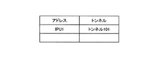
ハンドオーバ実施前の状態では、サーバ10がUE1に対して送信するパケットの送信元アドレスは「IPS」、送信先アドレスは「IPU1」である。当該パケットは、送信先アドレス「IPU1」によって、インターネット9内をルーティングされてGW8に到着する。図9は、GW8が保持するIPアドレスとトンネルの対応を示すテーブルである。GW8は、このテーブルに基づいて送信先アドレス「IPU1」となっているパケットをトンネル101に送信し、公衆アクセスネットワーク6内をトンネル101によりBTS2まで転送する。BTS2は、宛先アドレス「IPU1」のパケットをUE1に送信する。また、UE1がサーバ10に対して送信するパケットの送信元アドレスは「IPU1」、送信先アドレスは「IPS」である。BTS2も図9に示すテーブルと同様のテーブルを保持しており、BTS2は、送信元アドレスが「IPU1」であるパケットを、トンネル101を使用して送信する。当該パケットは、公衆アクセスネットワーク6内をトンネル101により伝送され、GW8に到着し、インターネット9内を送信先アドレス「IPS」によってルーティングされてサーバ10に到着する。
In a state before the handover is performed, the transmission source address of the packet transmitted from the
この状態から、BTS2をソース無線基地局、BTS3をターゲット無線基地局とするハンドオーバを実施する場合について説明する。まず、BTS2が、MME5に対してハンドオーバ要求を送信する(ステップS3001)。ハンドオーバ要求を受信したMME5は、ハンドオーバ要求をターゲット無線基地局であるBTS3に送信する(ステップS3002)。BTS3は、GW8との間にUE1のためのトンネルを生成する処理を実施する(ステップS3003)。
From this state, a case will be described in which handover is performed with BTS2 as the source radio base station and BTS3 as the target radio base station. First, the
トンネルを生成後、BTS3は、ハンドオーバを承認するハンドオーバ要求確認をMME5に送信する(ステップS3004)。MME5は、ハンドオーバの実施を通知するため、BTS2に対してハンドオーバ命令を送信する(ステップS3005)。ハンドオーバ命令を受信したBTS2は、UE1に対してハンドオーバ命令を送信する(ステップS3006)。BTS2は、UE1が使用していたUEアドレス「IPU1」をBTS3に通知するため、UEアドレス通知をMME5に送信する(ステップS3007)。UEアドレス通知を受信したMME5は、BTS3にUEアドレス通知を送信する(ステップS3008)。UEアドレス通知を受信したBTS3は、GW8での送信先アドレス「IPU1」の送信先をトンネル101からトンネル102に変更するため、転送先変更要求をGW8に送信する(ステップS3009)。GW8は、転送先変更要求を受信するとUEアドレスとトンネルの対応関係を保持するテーブルを更新する(ステップS3010)。図10は、GW8が保持する更新後のIPアドレスとトンネルの対応を示すテーブルである。アドレス「IPU1」に対してトンネル102が対応付けられている。
After generating the tunnel, the
一方、ステップS3006でハンドオーバ命令を受信したUE1は、接続先をBTS3に変更して、ハンドオーバ実施通知をBTS3に送信する(ステップS3011)これにより、BTS3は、UE1がハンドオーバを実施して自局に接続したことを認識する。 On the other hand, UE1 that has received the handover command in step S3006 changes the connection destination to BTS3, and transmits a handover execution notification to BTS3 (step S3011). Recognize that you are connected.
図11は、ハンドオーバ後の移動体通信システムの構成例を示す図である。BTS3とGW8間に設定されたトンネル102上をUE1とサーバ10間の通信データが転送される。
FIG. 11 is a diagram illustrating a configuration example of a mobile communication system after handover. Communication data between the
図10に示すハンドオーバを実施後、サーバ10が、送信元アドレス「IPS」、送信先アドレス「IPU1」としてUE1へパケットを送信すると、当該パケットは、インターネット9からGW8に到着する。GW8は、トンネル102によりパケットをBTS3に送信し、BTS3は、これをUE1に送信する(ステップS3012)。
After the handover shown in FIG. 10 is performed, when the
一方、UE1が、送信元アドレス「IPU1」、送信先アドレス「IPS」としてサーバ10へパケットを送信すると、BTS3がトンネル102によりGW8へ転送され、さらにインターネット9内をルーティングされてサーバ10にパケットが送信される(ステップS3013)。
On the other hand, when the
以上説明したように、本実施の形態では、オフロード通信中の無線端末がハンドオーバを実施する場合において、ハンドオーバ元の無線基地局は、ハンドオーバ先の無線基地局へ無線端末用アドレスを通知し、ハンドオーバ先の無線基地局は、公衆アクセスネットワークとインターネットの境界に位置するゲートウェイ装置に対して、無線端末用アドレスと対応するトンネルを通知して、当該無線端末用アドレスに対してゲートウェイ装置が使用するトンネルを変更させることとした。これにより、トンネルを構成して通信をしていた場合においても、無線端末とインターネット上のサーバでは、ハンドオーバ前とハンドオーバ後で同じ無線端末用アドレスを用いることができ、無線端末は、オフロード通信を継続したまま無線基地局を移動するハンドオーバを実施することができる。 As described above, in the present embodiment, when a radio terminal in offload communication performs handover, the handover source radio base station notifies the handover destination radio base station of the radio terminal address, The handover destination radio base station notifies the gateway device located at the boundary between the public access network and the Internet of the tunnel corresponding to the radio terminal address, and the gateway device uses the radio terminal address. It was decided to change the tunnel. As a result, even when a tunnel is configured for communication, the wireless terminal and the server on the Internet can use the same wireless terminal address before handover and after handover. The handover for moving the radio base station can be performed while continuing.
1 無線端末(UE)
2、3 無線基地局(BTS)
4 移動体通信コアネットワーク
5 移動管理装置(MME)
6 公衆アクセスネットワーク
7 ルータ
8 ゲートウェイ装置(GW)
9 インターネット
10 サーバ
101、102 トンネル
1 Radio terminal (UE)
2, 3 Radio base station (BTS)
4 Mobile
6
9
Claims (7)
ハンドオーバ元無線基地局が、ハンドオーバ先無線基地局に対して、自局における無線端末用アドレスである第1のアドレスの情報を通知する第1のアドレス通知ステップと、
ハンドオーバ先無線基地局が、前記ハンドオーバ元無線基地局に対して、自局における無線端末用アドレスである第2のアドレスの情報を通知する第2のアドレス通知ステップと、
ハンドオーバ元無線基地局が、前記インターネット上の装置から受信した前記無線端末あてのパケットの送信先アドレスを前記第1のアドレスから前記第2のアドレスに変換し、当該パケットを前記公衆アクセスネットワーク経由で前記ハンドオーバ先無線基地局に転送するハンドオーバ元無線基地局転送ステップと、
ハンドオーバ先無線基地局が、受信した前記パケットの送信先アドレスを前記第2のアドレスから前記第1のアドレスに変換し、当該パケットを前記無線端末に送信するハンドオーバ先無線基地局送信ステップと、
を含むことにより、オフロード通信を継続したままハンドオーバを実施することを特徴とするオフロードハンドオーバ方法。 An offload handover method in a mobile communication system in which a wireless terminal performs offload communication with a device on the Internet via a public access network without passing through a mobile core network via a wireless base station,
A first address notification step in which the handover source radio base station notifies the handover destination radio base station of information of a first address that is an address for a radio terminal in the own station;
A second address notification step in which the handover destination radio base station notifies the handover source radio base station of information of a second address that is an address for the radio terminal in the own station;
The handover source radio base station converts the transmission destination address of the packet addressed to the radio terminal received from the device on the Internet from the first address to the second address, and transmits the packet via the public access network. A handover source radio base station transfer step of transferring to the handover destination radio base station;
A handover destination radio base station transmitting a handover destination radio base station that converts a transmission destination address of the received packet from the second address to the first address and transmitting the packet to the radio terminal;
The offload handover method is characterized in that the handover is performed while continuing the offload communication.
ハンドオーバ元無線基地局が、ハンドオーバ先無線基地局に対して、自局における無線端末用アドレスである第1のアドレスの情報を通知するアドレス通知ステップと、
ハンドオーバ先無線基地局が、受信した前記第1のアドレスと自局における無線端末用アドレスである第2のアドレスとを比較するアドレス比較ステップと、
ハンドオーバ先無線基地局が、前記比較した結果、前記ハンドオーバ元無線基地局と自局が同一サブネットに属することを検出した場合に、前記公衆アクセスネットワークに対して、送信先アドレスが第1のアドレスである前記無線端末あてのパケットの送信先を前記ハンドオーバ元無線基地局から自局に変更させる送信先変更ステップと、
ハンドオーバ先無線基地局が、前記インターネット上の装置から受信した送信先アドレスが第1のアドレスである前記無線端末あてのパケットを、前記無線端末に送信するハンドオーバ先無線基地局送信ステップと、
を含むことにより、オフロード通信を継続したままハンドオーバを実施することを特徴とするオフロードハンドオーバ方法。 An offload handover method in a mobile communication system in which a wireless terminal performs offload communication with a device on the Internet via a public access network without passing through a mobile core network via a wireless base station,
An address notification step in which the handover source radio base station notifies the handover destination radio base station of the information of the first address that is the address for the radio terminal in the local station;
An address comparison step in which the handover destination radio base station compares the received first address with a second address that is a radio terminal address in the own station;
As a result of the comparison, when the handover destination radio base station detects that the handover source radio base station and its own station belong to the same subnet, the destination address is the first address for the public access network. A transmission destination changing step for changing a transmission destination of a packet addressed to a certain wireless terminal from the handover source wireless base station to the own station;
A handover destination radio base station transmitting step, wherein the handover destination radio base station sends a packet addressed to the radio terminal whose destination address received from the device on the Internet is a first address;
The offload handover method is characterized in that the handover is performed while continuing the offload communication.
前記ゲートウェイ装置との間で第1のトンネルを設定してパケット転送しているハンドオーバ元無線基地局が、ハンドオーバ先無線基地局に対して、自局における無線端末用アドレスの情報を通知するアドレス通知ステップと、
ハンドオーバ先無線基地局が、前記ゲートウェイ装置との間に設定した第2のトンネルについて、前記ゲートウェイ装置に対して、前記インターネット上の装置から受信した前記無線端末用アドレスを送信先とするパケットの場合の転送先を、前記第1のトンネルから前記第2のトンネルに変更させるトンネル変更ステップと、
ハンドオーバ先無線基地局が、前記無線端末から受信した前記インターネット上の装置あてのパケットの送信先を、前記第2のトンネルを用いて転送するパケット転送ステップと、
を含むことにより、オフロード通信を継続したままハンドオーバを実施することを特徴とするオフロードハンドオーバ方法。 The radio terminal uses the tunnel set up between the radio base station and the gateway device that connects the public access network and the Internet via the radio base station, without going through the mobile core network, and the public access An offload handover method in a mobile communication system that performs packet transfer in a network and performs offload communication with a device on the Internet via the gateway device,
An address notification in which a handover source radio base station that sets up a first tunnel with the gateway device and transfers packets notifies the handover destination radio base station of information on the address for the radio terminal in the own station Steps,
For a second tunnel set up between the handover destination radio base station and the gateway device, a packet whose destination is the radio terminal address received from the device on the Internet to the gateway device A tunnel change step of changing the transfer destination of the first tunnel from the first tunnel;
A packet transfer step in which a handover destination radio base station transfers, using the second tunnel, a destination of a packet received from the radio terminal and addressed to the device on the Internet;
The offload handover method is characterized in that the handover is performed while continuing the offload communication.
ハンドオーバ元無線基地局の場合は、
ハンドオーバ先無線基地局に対して、自局における無線端末アドレスである第1のアドレスの情報を通知し、また、前記インターネット上の装置から受信した前記無線端末あてのパケットの送信先アドレスを、ハンドオーバ先無線基地局から通知された当該ハンドオーバ先無線基地局における無線端末アドレスである第2のアドレスに変換し、当該パケットを前記公衆アクセスネットワーク経由で前記ハンドオーバ先無線基地局に転送し、
ハンドオーバ先無線基地局の場合は、
前記ハンドオーバ元無線基地局に対して、前記第2のアドレスの情報を通知し、また、前記公衆アクセスネットワーク経由で前記ハンドオーバ元無線基地局から受信したパケットの送信先アドレスを、前記第2のアドレスから前記第1のアドレスに変換し、前記無線端末に送信する、
ことにより、オフロード通信を継続したままハンドオーバを実施することを特徴とする無線基地局。 The wireless base station is an unrelated base station in a mobile communication system that performs offload communication with a device on the Internet through a public access network without going through a mobile core network via a wireless base station,
For the handover source radio base station,
The handover destination radio base station is notified of the information of the first address which is the radio terminal address in the local station, and the destination address of the packet addressed to the radio terminal received from the device on the Internet is handed over Converting to a second address that is a radio terminal address in the handover destination radio base station notified from the destination radio base station, and transferring the packet to the handover destination radio base station via the public access network;
In the case of a handover destination radio base station,
The handover source radio base station is notified of the second address information, and the destination address of a packet received from the handover source radio base station via the public access network is set to the second address. To the first address and transmit to the wireless terminal,
Thus, a radio base station that performs handover while continuing off-road communication.
ハンドオーバ元無線基地局の場合は、
ハンドオーバ先無線基地局に対して、自局における無線端末用アドレスである第1のアドレスの情報を通知し、
ハンドオーバ先無線基地局の場合は、
受信した前記第1のアドレスと自局における無線端末用アドレスである第2のアドレスとを比較し、比較した結果、前記ハンドオーバ元無線基地局と自局が同一サブネットに属することを検出したときは、前記公衆アクセスネットワークに対して、送信先アドレスが第1のアドレスである前記無線端末あてのパケットの送信先を前記ハンドオーバ元無線基地局から自局に変更させ、前記インターネット上の装置から受信した送信先アドレスが第1のアドレスである前記無線端末あてのパケットを、前記無線端末に送信する、
ことにより、オフロード通信を継続したままハンドオーバを実施することを特徴とする無線基地局。 The radio base station in the mobile communication system in which the radio terminal performs offload communication with a device on the Internet via the public access network without going through the mobile core network via the radio base station,
For the handover source radio base station,
Notifying the handover destination radio base station of the information of the first address that is the address for the radio terminal in the own station,
In the case of a handover destination radio base station,
When the received first address is compared with the second address that is the address for the wireless terminal in the local station, and as a result of comparison, when it is detected that the handover source wireless base station and the local station belong to the same subnet The destination address of the packet destined for the wireless terminal whose destination address is the first address is changed from the handover source radio base station to the local station and received from the device on the Internet. A packet addressed to the wireless terminal whose destination address is the first address is transmitted to the wireless terminal;
Thus, a radio base station that performs handover while continuing off-road communication.
ハンドオーバ元無線基地局の場合は、
ハンドオーバ前は前記ゲートウェイ装置との間で第1のトンネルを設定してパケット転送し、ハンドオーバ先無線基地局に対して、自局における無線端末用アドレスの情報を通知し、
ハンドオーバ先無線基地局の場合は、
前記ゲートウェイ装置との間に設定した第2のトンネルについて、前記ゲートウェイ装置に対して、前記インターネット上の装置から受信した前記無線端末用アドレスを送信先とするパケットの場合の転送先を、前記第1のトンネルから前記第2のトンネルに変更させ、前記無線端末から受信した前記インターネット上の装置あてのパケットの送信先を、前記第2のトンネルを用いて転送する、
ことにより、オフロード通信を継続したままハンドオーバを実施することを特徴とする無線基地局。 The radio terminal uses the tunnel set up between the radio base station and the gateway device that connects the public access network and the Internet via the radio base station, without going through the mobile core network, and the public access The wireless base station in a mobile communication system that performs packet transfer in a network and performs offload communication with a device on the Internet via the gateway device,
For the handover source radio base station,
Before handover, the first tunnel is set up with the gateway device to transfer the packet, and the handover destination radio base station is notified of the address information for the radio terminal in its own station,
In the case of a handover destination radio base station,
For the second tunnel set up with the gateway device, a forwarding destination in the case of a packet with the address for the wireless terminal received from the device on the Internet as the destination is sent to the gateway device. The first tunnel is changed to the second tunnel, and the transmission destination of the packet addressed to the device on the Internet received from the wireless terminal is transferred using the second tunnel.
Thus, a radio base station that performs handover while continuing off-road communication.
ハンドオーバ実施時にハンドオーバ先無線基地局との間で新たにトンネルを設定し、前記ハンドオーバ先無線基地局からの要求に従って、ハンドオーバ元無線基地局における無線端末用アドレスを送信先とするパケットの転送先を、前記ハンドオーバ先無線基地局との間に設定したトンネルに変更する、
ことを特徴とするゲートウェイ装置。 The radio terminal uses the tunnel set up between the radio base station and the gateway device that connects the public access network and the Internet via the radio base station, without going through the mobile core network, and the public access The gateway device in a mobile communication system that performs packet transfer in a network and performs offload communication with a device on the Internet via the gateway device,
A tunnel is newly set up with the handover destination radio base station at the time of handover, and in accordance with a request from the handover destination radio base station, a packet transfer destination having a radio terminal address in the handover source radio base station as a transmission destination is set. , Change to the tunnel set up with the handover destination radio base station,
A gateway device characterized by that.
Priority Applications (1)
| Application Number | Priority Date | Filing Date | Title |
|---|---|---|---|
| JP2011126565A JP2012253680A (en) | 2011-06-06 | 2011-06-06 | Offload handover method, radio base station and gateway device |
Applications Claiming Priority (1)
| Application Number | Priority Date | Filing Date | Title |
|---|---|---|---|
| JP2011126565A JP2012253680A (en) | 2011-06-06 | 2011-06-06 | Offload handover method, radio base station and gateway device |
Publications (1)
| Publication Number | Publication Date |
|---|---|
| JP2012253680A true JP2012253680A (en) | 2012-12-20 |
Family
ID=47526045
Family Applications (1)
| Application Number | Title | Priority Date | Filing Date |
|---|---|---|---|
| JP2011126565A Withdrawn JP2012253680A (en) | 2011-06-06 | 2011-06-06 | Offload handover method, radio base station and gateway device |
Country Status (1)
| Country | Link |
|---|---|
| JP (1) | JP2012253680A (en) |
Cited By (2)
| Publication number | Priority date | Publication date | Assignee | Title |
|---|---|---|---|---|
| CN103338488A (en) * | 2013-06-21 | 2013-10-02 | 华为技术有限公司 | Network switching method, terminal, controller, gateway and system |
| JP2016529812A (en) * | 2013-08-08 | 2016-09-23 | ゼットティーイー コーポレーションZte Corporation | Information interaction, offload processing method, apparatus, base station, RNC and terminal |
-
2011
- 2011-06-06 JP JP2011126565A patent/JP2012253680A/en not_active Withdrawn
Cited By (6)
| Publication number | Priority date | Publication date | Assignee | Title |
|---|---|---|---|---|
| CN103338488A (en) * | 2013-06-21 | 2013-10-02 | 华为技术有限公司 | Network switching method, terminal, controller, gateway and system |
| WO2014201868A1 (en) * | 2013-06-21 | 2014-12-24 | 华为技术有限公司 | Method, terminal, controller, gateway, and system for network switchover |
| CN103338488B (en) * | 2013-06-21 | 2016-03-09 | 华为技术有限公司 | Method for switching network, terminal, controller, gateway and system |
| US9723521B2 (en) | 2013-06-21 | 2017-08-01 | Huawei Technologies Co., Ltd. | Network handover method, terminal, controller, gateway, and system |
| JP2016529812A (en) * | 2013-08-08 | 2016-09-23 | ゼットティーイー コーポレーションZte Corporation | Information interaction, offload processing method, apparatus, base station, RNC and terminal |
| US10117151B2 (en) | 2013-08-08 | 2018-10-30 | Zte Corporation | Method and device for processing information interaction, offloading processing method and device, base station, RNC and UE |
Similar Documents
| Publication | Publication Date | Title |
|---|---|---|
| EP2490469B1 (en) | Mobile communication system, gateway device, base station device, control method for gateway device, and computer-readable medium | |
| KR102086275B1 (en) | Interoperability with Legacy Wireless Access Technologies for Connectivity to Next-Generation Core Networks | |
| KR101560067B1 (en) | Methods and apparatus for managing a handover between base stations | |
| US8804682B2 (en) | Apparatus for management of local IP access in a segmented mobile communication system | |
| KR101894647B1 (en) | System and method for optimized route mobility management | |
| KR101495063B1 (en) | Network device and method for local routing of data traffic | |
| JP5227960B2 (en) | Packet transfer for proxy mobile IP | |
| EP3154288B1 (en) | Apparatus and method for callconnecting at femtocells | |
| JP5690934B2 (en) | Apparatus and method for local mobility management in a clustered femtocell network | |
| JP4472537B2 (en) | Packet control apparatus, authentication server, and wireless communication system | |
| KR101581282B1 (en) | Method and apparatus for supporting local internet protocol access at wireless communication network comprising femto cell | |
| JP2016034139A (en) | Communication system | |
| JP4968328B2 (en) | Mobile IP communication system, mobile IP communication apparatus, and mobile IP communication method | |
| KR20100029833A (en) | Handover trigger for an inter-access-gateway interface | |
| US20140269588A1 (en) | Radio communication device for mobile communication system | |
| CN106686572B (en) | SDN-based mobility management method | |
| JP5536895B2 (en) | IP subnet address assignment within a local network that contains multiple devices and is connected to the Internet | |
| WO2017095053A1 (en) | Method and apparatus for setting up relay link in wireless communication system | |
| JP5790503B2 (en) | Mobile communication system, gateway device, base station, communication method and program | |
| WO2011096781A2 (en) | Method for handling mobility of a wireless terminal | |
| JP2011130387A (en) | Relay apparatus and radio communication system | |
| JP5645035B2 (en) | Communications system | |
| JP2012253680A (en) | Offload handover method, radio base station and gateway device | |
| KR101598602B1 (en) | System fof x2 handover management of femtocell and method fof controling of x2 handover using the same | |
| Noriega-Vivas et al. | Supporting l3 femtocell mobility using the mobike protocol |
Legal Events
| Date | Code | Title | Description |
|---|---|---|---|
| A300 | Withdrawal of application because of no request for examination |
Free format text: JAPANESE INTERMEDIATE CODE: A300 Effective date: 20140902 |