JP2012251499A - Propeller structure for tidal current power generator - Google Patents
Propeller structure for tidal current power generator Download PDFInfo
- Publication number
- JP2012251499A JP2012251499A JP2011125466A JP2011125466A JP2012251499A JP 2012251499 A JP2012251499 A JP 2012251499A JP 2011125466 A JP2011125466 A JP 2011125466A JP 2011125466 A JP2011125466 A JP 2011125466A JP 2012251499 A JP2012251499 A JP 2012251499A
- Authority
- JP
- Japan
- Prior art keywords
- blade
- output shaft
- tidal current
- shaft
- propeller structure
- Prior art date
- Legal status (The legal status is an assumption and is not a legal conclusion. Google has not performed a legal analysis and makes no representation as to the accuracy of the status listed.)
- Pending
Links
Images


Classifications
-
- Y—GENERAL TAGGING OF NEW TECHNOLOGICAL DEVELOPMENTS; GENERAL TAGGING OF CROSS-SECTIONAL TECHNOLOGIES SPANNING OVER SEVERAL SECTIONS OF THE IPC; TECHNICAL SUBJECTS COVERED BY FORMER USPC CROSS-REFERENCE ART COLLECTIONS [XRACs] AND DIGESTS
- Y02—TECHNOLOGIES OR APPLICATIONS FOR MITIGATION OR ADAPTATION AGAINST CLIMATE CHANGE
- Y02E—REDUCTION OF GREENHOUSE GAS [GHG] EMISSIONS, RELATED TO ENERGY GENERATION, TRANSMISSION OR DISTRIBUTION
- Y02E10/00—Energy generation through renewable energy sources
- Y02E10/20—Hydro energy
-
- Y—GENERAL TAGGING OF NEW TECHNOLOGICAL DEVELOPMENTS; GENERAL TAGGING OF CROSS-SECTIONAL TECHNOLOGIES SPANNING OVER SEVERAL SECTIONS OF THE IPC; TECHNICAL SUBJECTS COVERED BY FORMER USPC CROSS-REFERENCE ART COLLECTIONS [XRACs] AND DIGESTS
- Y02—TECHNOLOGIES OR APPLICATIONS FOR MITIGATION OR ADAPTATION AGAINST CLIMATE CHANGE
- Y02E—REDUCTION OF GREENHOUSE GAS [GHG] EMISSIONS, RELATED TO ENERGY GENERATION, TRANSMISSION OR DISTRIBUTION
- Y02E10/00—Energy generation through renewable energy sources
- Y02E10/30—Energy from the sea, e.g. using wave energy or salinity gradient
Abstract
Description
本発明は、潮流発電機用のプロペラ構造に関する。 The present invention relates to a propeller structure for a tidal current generator.
従来から、潮流エネルギーを用いて発電を行うための潮流発電機用のプロペラ構造として特許文献1に記載されたものが知られている。
Conventionally, what was described in
特許文献1には、互いに回動可能に連結された二枚のブレードで開閉回転羽根を形成し、この開閉回転羽根をシャフト周りに90度間隔で4枚配置したロータを備えたプロペラ構造が記載されている。また、特許文献1には、このようなロータを複数個設けることにより、プロペラ構造による出力トルクを増加させることが記載されている。
しかしながら、特許文献1のプロペラ構造では、各々のロータにおけるブレードの位置関係について考慮されていないため、例えば、プロペラ構造を出力シャフトの軸線方向に沿ってみたときに、全てのロータのブレードが重なるような位置関係を有している場合には、重なっているブレードが同時に潮流を受けて出力シャフトの回転加速度を増加させる。反対に、隣接するブレード間の角度を二等分した位置にある面が潮流と直交するような位置では、全てのブレードが潮流を受け流してしまうので、出力シャフトの回転加速度を増加させることはできない。このように特許文献1に記載されたプロペラ構造では、出力シャフトの回転加速度を安定させることができず、結果として潮流発電装置による発電量を安定させることができないという問題があった。
However, in the propeller structure of
そこで本発明は、上述した問題点を解決するためになされたものであり、出力シャフトの回転加速度を安定させることにより、安定した発電量を得ることができる潮流発電装置用のプロペラ構造を提供することを目的とする。 Accordingly, the present invention has been made to solve the above-described problems, and provides a propeller structure for a tidal current power generation device that can obtain a stable power generation amount by stabilizing the rotational acceleration of an output shaft. For the purpose.
上述した課題を解決するために、本発明は、潮流発電装置用のプロペラ構造において、潮流発電装置の発電機に接続される出力シャフトと、この出力シャフトに固定されたm個のロータとを備え、m個のロータの各々は、出力ャフトを中心に放射状に延び、互いに等角度をなして出力シャフトに固定されたn個の翼部を有し、翼部の各々は、潮流を受けるようになったブレードと、出力シャフトと直交方向に延びブレードを回動自在に支持するようになった支持シャフトと、ブレードが回動してブレードの面が出力シャフトと平行になる状態でブレードの回動を規制する規制部材とを有し、ロータは、上面視したときに、m個のロータの全てのブレードが、隣接するブレードに対してシャフトの軸周りに360/(mn)度の間隔をもって配置されていること特徴とする。 In order to solve the above-described problems, the present invention includes, in a propeller structure for a tidal current power generation device, an output shaft connected to a power generator of the tidal current power generation device, and m rotors fixed to the output shaft. Each of the m rotors extends radially about the output shaft and has n wings that are equiangular with each other and secured to the output shaft so that each wing receives a tidal current. Blade, a support shaft that extends in a direction orthogonal to the output shaft and supports the blade in a rotatable manner, and the blade rotates in a state where the blade rotates and the surface of the blade is parallel to the output shaft. When the rotor is viewed from above, all the blades of the m rotors are arranged around the shaft axis with an interval of 360 / (mn) degrees with respect to the adjacent blades. Wherein we are.
このように構成された本発明によれば、出力シャフトと直交する支持シャフトに対して回動可能に支持されたブレードを備えるプロペラ構造における全てのプロペラを、出力シャフトの周囲に、等しい角度間隔で配置することができる。そしてこのように全てのプロペラを等しい角度間隔に配置することによって、潮流を受けて回転するプロペラ構造の回転時の角加速度を常に、ほぼ一定に保つことができる。 According to the present invention configured as described above, all the propellers in the propeller structure including the blades rotatably supported with respect to the support shaft orthogonal to the output shaft are arranged at equal angular intervals around the output shaft. Can be arranged. By arranging all the propellers at equal angular intervals in this way, the angular acceleration during rotation of the propeller structure that rotates in response to the power flow can always be kept substantially constant.
また、本発明において、好ましくは、規制部材は、所定の間隔をもって支持シャフトと平行に延び、出力シャフトと平行な状態にあるブレードと接触して当該ブレードの回動を規制する規制シャフトを備える。
このように構成された本発明によれば、簡単な構造によって、支持シャフトに対するブレードの回動範囲を制限することができる。
In the present invention, it is preferable that the restricting member includes a restricting shaft that extends in parallel with the support shaft at a predetermined interval and contacts the blade in parallel with the output shaft to restrict the rotation of the blade.
According to the present invention configured as described above, the rotation range of the blade relative to the support shaft can be limited with a simple structure.
また、本発明において、好ましくは、規制シャフトは、支持シャフトよりも下側において出力シャフトに固定されており、ブレードの上端近傍が、支持シャフトに回動自在に支持され、ブレードの下端近傍が規制シャフトに接触するようになっている。
このように構成された本発明によれば、潮流を受けて水平状態まで回動したブレードを、簡単な構造を用いて、重力を利用して出力シャフトと平行な状態に戻すことができる。
In the present invention, preferably, the restriction shaft is fixed to the output shaft below the support shaft, the upper end vicinity of the blade is rotatably supported by the support shaft, and the lower end vicinity of the blade is restricted. It comes in contact with the shaft.
According to the present invention configured as described above, the blade rotated to the horizontal state upon receiving the tidal current can be returned to a state parallel to the output shaft using gravity with a simple structure.
また、本発明において好ましくは、規制シャフトとブレードが接触する箇所に設けられた緩衝部材をさらに備える。
このように構成された本発明によれば、緩衝部材によってブレードと規制シャフトとの間の衝撃を低減することができる。
In the present invention, it is preferable to further include a buffer member provided at a location where the regulating shaft and the blade are in contact with each other.
According to the present invention configured as described above, the shock between the blade and the regulating shaft can be reduced by the buffer member.
以上のように、本発明によれば、潮流発電装置用のプロペラ構造において、出力シャフトの回転加速度を安定させることができ、これにより潮流発電装置の発電量を安定させることができる。 As described above, according to the present invention, in the propeller structure for a tidal current power generator, the rotational acceleration of the output shaft can be stabilized, and thereby the power generation amount of the tidal current power generator can be stabilized.
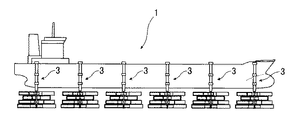
以下、図面を参照して、本発明の実施形態による潮流発電装置用のプロペラ構造について説明する。図1は、本発明の実施形態にかかるプロペラ構造を備えた潮流発電装置を載せた台船の側面図であり、図2は、図1の台船の底面図である。 Hereinafter, a propeller structure for a tidal current power generator according to an embodiment of the present invention will be described with reference to the drawings. FIG. 1 is a side view of a trolley on which a tidal current power generation apparatus having a propeller structure according to an embodiment of the present invention is mounted, and FIG. 2 is a bottom view of the trolley of FIG.
図1及び2に示すように、潮流発電装置1は、複数のプロペラ構造3と、複数の発電機5を備えており、各々のプロペラ構造3で得られたエネルギーを発電機5に伝達して電力を発生させるようになっている。台船上の発電機5は、送電線(図示せず)を介して陸上の変電設備に接続されている。そして潮流発電装置1は、海上において潮流によってプロペラ構造3を回転させて、そのエネルギーを発電機5において電力に変換するようになっている。
As shown in FIGS. 1 and 2, the tidal current
台船には、複数のプロペラ構造3が搭載されており、各々のプロペラ構造3は同一の構造を有している。プロペラ構造3は、台船の両側にそれぞれ六個ずつ等間隔で配列されている。
A plurality of
図3は、プロペラ構造3の立面図であり、図4は、このプロペラ構造3の上面図である。プロペラ構造3は、発電機5に接続される出力シャフト7と、この出力シャフト7に固定された複数のロータ9とを備える。垂直方向に延びる出力シャフト7の上端は、発電機5の回転子を有する軸受けに固定されており、潮流によって回転するロータ9のエネルギーを、回転力として発電機5に伝達するようになっている。また、複数のロータ9は、出力シャフト7の軸線方向に沿って互いに重なるようになっている。
FIG. 3 is an elevation view of the
ロータ9は、出力シャフト7と直交する方向において、出力シャフト7を中心として放射状に延びる複数の翼部11を有している。一つのロータ9に設けられた複数の翼部11は、互いに等しい角度間隔で出力シャフト7に固定されている。そして本実施形態では、一つのロータ9に、四枚の翼部11が設けられており、一つのロータ9における各翼部11は、隣接する翼部11から出力シャフト7の周方向に90度離れた位置において出力シャフト7に固定されている。そしてロータ9は、後述するように、潮流を受けて回転するようになっており、ロータ9が出力シャフト回りに回転したときの軌跡で形成される円の直径は、例えば7200mm乃至7300mm程度とされる。
尚、本実施形態では、プロペラ構造3が四個のロータ9を備えているものとするが、本発明によるプロペラ構造では、ロータの個数(m:m>1)を適宜変更することができる。また、一つのロータ9に四個の翼部11が設けられているものとするが、本発明によるプロペラ構造では、一つのロータに設けられる翼部の個数(n:n>1)は四個に限られるものではない。
The
In this embodiment, it is assumed that the
ロータ9に設けられた四個の翼部11は、全て同一の構造を有しており、各翼部11は、潮流を受けるためのブレード13と、ブレード13を出力シャフト7に対して支持するための支持シャフト15とを備える。支持シャフト15は、一端が出力シャフト7に固定されており、そこから出力シャフト7と直交するように延びている。そして、支持シャフト15の他端側には、ブレード13が支持シャフト15に対して回動可能に支持されている。また、翼部11は、ブレード13の回動を規制するための規制シャフト17を有している。この規制シャフト17は、出力シャフト7から支持シャフト15と平行に且つ出力シャフト7と直交するように延びている。そして規制シャフト17は、支持シャフト15よりも下方において、出力シャフト7に固定されている。また、支持シャフト15と規制シャフト17との間には、複数のリブ部材19がわたされており、これにより支持シャフト15、規制シャフト17、及びリブ部材19によって、梯子状のフレーム21を形成している。
The four
ブレード13は、例えば高さ610mm、長さ2400mm程度の長方形の板状部材によって構成されており、この長方形の面が潮流に対して所定の角度を有するときに潮流を受けて、潮流によるエネルギーを、支持シャフト15を通じて出力シャフト7に伝達するようになっている。また、ブレード13の面によって受けた潮流が出力シャフト7の回転させるモーメントを作り出すことを考慮して、ブレード13の先端と、支持シャフト15(及び規制シャフト17)の先端とを整列させて、出力シャフト7に加わるモーメントを大きくするようにすることが好ましい。
The
図5は、翼部の断面図である。支持シャフト15の回りには、支持シャフト15の外径よりも大きい内径を有するリング部材23が設けられており、このリング部材23は、ブレード13の上端近傍に固定されている。また、規制シャフト17におけるブレード13と接触する側には、緩衝部材25が設けられており、ブレード13の下端近傍が接触するようになっている。このようなブレード13は、フレーム21に対して、プロペラ構造3の回転の上流側に配置されている。そしてブレード13は、リング部材23を介して支持シャフト15回りを回動するようになっており、ブレード13の面がほぼ垂直(出力シャフトと平行な状態)になったときに、ブレード13の下端が緩衝部材25に接触し、これによりブレード13が支持シャフト15回りにそれ以上回動しないようになっている。
FIG. 5 is a cross-sectional view of the wing portion. A
本実施形態によるプロペラ構造3は、上述した四個の翼部11を有するロータ9を四つ有する。そして各ロータ9は、互いに、出力シャフト7の軸回りに所定の角度をもって固定されている。従って、プロペラ構造3を上面視した場合、図4に示すように、合計十六個の翼部11が出力シャフト7を中心に放射状に延びるようになっている。そして上面視したときの隣接する翼部11同士の角度は、360/(ロータの個数×ロータ毎の翼部の個数)によって決定される。従って、四個のロータ9がそれぞれ四個の翼部11を有しているプロペラ構造3では、上面視したときに隣接する翼部11同士の角度が22.5度になるように設定される。この角度の調整は、ロータ9を出力シャフト7に固定するときに、上下に隣接するロータ9同士を22.5度ずつずらして固定することで行われる。
The
次に、本発明の実施形態によるプロペラ構造の動作について説明する。図6は、プロペラ構造3の一個のロータ9の上面図を示す。同図における直線矢印Aは、潮の流れる方向を示し、曲線矢印Bは、プロペラ構造3の回転方向を示す。また、以下では、説明の便宜状、四個の翼部11を、プロペラ構造3の回転方向上流側から、各々、第一翼部11a、第二翼部11b、第三翼部11c、第四翼部11dと称して説明する。同図では、第一翼部11a及び第三翼部11cのブレード13の面が潮流に対して直交する方向に延びており、第二翼部11b及び第四翼部11dのブレード13が、潮流に対してほぼ平行に延びている。
Next, the operation of the propeller structure according to the embodiment of the present invention will be described. FIG. 6 shows a top view of one
同図に示す状態では、第一翼部11aのブレード13は、フレーム21に対して潮流の上流側に位置しているので、このブレード13の面に潮流を受けると、ブレード13がフレーム21に押しつけられ、潮流の力によって出力シャフト7を回転させるモーメントが発生する。またこのとき第二翼部11bのブレード13は、潮流に対してほぼ平行方向に延びているので、潮流の影響を受けない。またこのとき第三翼部11cのブレード13は、フレーム21に対して潮流の下流側に位置しているので、このブレード13によって潮流を受けると、ブレード13は支持シャフト17回りに回動して、ほぼ水平状態になる。これにより、潮流はブレード13に当たることなく、フレーム21の開口部を通って下流側に流れる。
In the state shown in the figure, the
このように一つのプロペラ構造3では、主に、上述した第一翼部11aのように、ブレード13がフレーム21に対して潮流の上流側に位置し、且つ潮流に対して直交方向に延びている翼部11a,11b,11c,11dによって出力シャフト7を回転させるエネルギーを発生させる。そして、一つのプロペラ構造3では、図6に示すように、一個の翼部11のブレード13がフレーム21に対して潮流の上流側に位置し、且つ潮流に対して直交方向に延びている状態にあるときに、出力シャフト7に伝達されるエネルギーが最大となると考えられる。そして、上述したように、複数のロータ9を形成し、プロペラ構造3を上面視したときに、全てのロータ9の全ての翼部11が、隣接する翼部11に対して出力シャフト7の軸周りに360/(mn)度の間隔をもって配置することにより、何れかのロータ9の翼部11のブレード13がフレーム21に対して潮流の上流側に位置し、且つ潮流に対して直行方向に延びている状態を継続的に作り出すことができる。これにより、出力シャフト7に伝達されるエネルギーが比較的多い状態を保つことができる。
Thus, in one
以下、本発明の実施例について詳述する。以下では、それぞれ、幅2438mm、高さ610mmのブレードを4個有する4個のロータを備えたプロペラ構造を、所定の流速で流れる水の中に入れた場合における、プロペラ構造の角速度・角加速度を計測した結果を示す。角速度の計測は、水上からプロペラ構造を撮影し、この画像を経時的に解析することにより行った。 Examples of the present invention will be described in detail below. In the following, when the propeller structure including four rotors each having four blades having a width of 2438 mm and a height of 610 mm is placed in water flowing at a predetermined flow velocity, the angular velocity and angular acceleration of the propeller structure are shown. The measured result is shown. The angular velocity was measured by photographing the propeller structure from the water and analyzing this image over time.
図7は、流速0.5m/sで流れる水の中でのプロペラ構造の角速度を示すグラフであり、図8は、該条件におけるプロペラ構造の角加速度を示すグラフである。図9は、流速1.0m/sで流れる水の中でのプロペラ構造の角速度を示すグラフであり、図10は、該条件におけるプロペラ構造の角加速度を示すグラフである。図11は、流速1.5m/sで流れる水の中でのプロペラ構造の角速度を示すグラフであり、図12は、該条件におけるプロペラ構造の角加速度を示すグラフである。図13は、流速2.0m/sで流れる水の中でのプロペラ構造の角速度を示すグラフであり、図14は、該条件におけるプロペラ構造の角加速度を示すグラフである。 FIG. 7 is a graph showing the angular velocity of the propeller structure in water flowing at a flow rate of 0.5 m / s, and FIG. 8 is a graph showing the angular acceleration of the propeller structure under the conditions. FIG. 9 is a graph showing the angular velocity of the propeller structure in water flowing at a flow rate of 1.0 m / s, and FIG. 10 is a graph showing the angular acceleration of the propeller structure under the conditions. FIG. 11 is a graph showing the angular velocity of the propeller structure in water flowing at a flow rate of 1.5 m / s, and FIG. 12 is a graph showing the angular acceleration of the propeller structure under the conditions. FIG. 13 is a graph showing the angular velocity of the propeller structure in water flowing at a flow rate of 2.0 m / s, and FIG. 14 is a graph showing the angular acceleration of the propeller structure under the conditions.
これらの図に示すように、何れの流速においてもプロペラ構造の角加速度の増減は非常に少ないことが分かる。 As shown in these figures, it can be seen that the increase or decrease in the angular acceleration of the propeller structure is very small at any flow rate.
1 潮流発電装置
3 プロペラ構造
5 発電機
7 出力シャフト
9 ロータ
11 翼部
13 ブレード
15 支持シャフト
17 規制シャフト
25 緩衝部材
DESCRIPTION OF
Claims (4)
前記潮流発電装置の発電機に接続される出力シャフトと、
この出力シャフトに固定されたm個のロータとを備え、
m個のロータの各々は、前記出力ャフトを中心に放射状に延び、互いに等角度をなして前記出力シャフトに固定されたn個の翼部を有し、
前記翼部の各々は、潮流を受けるようになったブレードと、前記出力シャフトと直交方向に延び前記ブレードを回動自在に支持するようになった支持シャフトと、前記ブレードが回動して当該ブレードの面が前記出力シャフトと平行になる状態で前記ブレードの回動を規制する規制部材とを有し、
前記ロータは、上面視したときに、前記m個のロータの全ての前記ブレードが、隣接するブレードに対して前記シャフトの軸周りに360/(mn)度の間隔をもって配置されている、プロペラ構造。 In the propeller structure for tidal current power generators,
An output shaft connected to the generator of the tidal current generator;
M rotors fixed to the output shaft,
each of the m rotors has n wings extending radially about the output shaft and fixed to the output shaft at equal angles to each other;
Each of the wings includes a blade adapted to receive a tidal current, a support shaft extending in a direction orthogonal to the output shaft and configured to rotatably support the blade, and the blade rotating to A regulating member that regulates the rotation of the blade in a state where the surface of the blade is parallel to the output shaft,
The rotor has a propeller structure in which when viewed from above, all the blades of the m rotors are arranged with an interval of 360 / (mn) degrees around the axis of the shaft with respect to adjacent blades. .
Priority Applications (1)
| Application Number | Priority Date | Filing Date | Title |
|---|---|---|---|
| JP2011125466A JP2012251499A (en) | 2011-06-03 | 2011-06-03 | Propeller structure for tidal current power generator |
Applications Claiming Priority (1)
| Application Number | Priority Date | Filing Date | Title |
|---|---|---|---|
| JP2011125466A JP2012251499A (en) | 2011-06-03 | 2011-06-03 | Propeller structure for tidal current power generator |
Publications (1)
| Publication Number | Publication Date |
|---|---|
| JP2012251499A true JP2012251499A (en) | 2012-12-20 |
Family
ID=47524530
Family Applications (1)
| Application Number | Title | Priority Date | Filing Date |
|---|---|---|---|
| JP2011125466A Pending JP2012251499A (en) | 2011-06-03 | 2011-06-03 | Propeller structure for tidal current power generator |
Country Status (1)
| Country | Link |
|---|---|
| JP (1) | JP2012251499A (en) |
Cited By (1)
| Publication number | Priority date | Publication date | Assignee | Title |
|---|---|---|---|---|
| CN106089555A (en) * | 2016-08-22 | 2016-11-09 | 青岛市机械工业总公司 | A kind of marine tidal-current energy generating kenetic energy converting device |
Citations (4)
| Publication number | Priority date | Publication date | Assignee | Title |
|---|---|---|---|---|
| JPS5629278U (en) * | 1979-08-11 | 1981-03-19 | ||
| JPH04137270U (en) * | 1991-06-18 | 1992-12-21 | 実 伊藤 | Variable blade type and rotating blades for wind and hydroelectric generators |
| JPH0960573A (en) * | 1995-08-21 | 1997-03-04 | Hakko Denki Kk | Wind power generator |
| US20080203731A1 (en) * | 2005-12-05 | 2008-08-28 | Dulcetti Filho Flavio Francisc | Eolic converter |
-
2011
- 2011-06-03 JP JP2011125466A patent/JP2012251499A/en active Pending
Patent Citations (4)
| Publication number | Priority date | Publication date | Assignee | Title |
|---|---|---|---|---|
| JPS5629278U (en) * | 1979-08-11 | 1981-03-19 | ||
| JPH04137270U (en) * | 1991-06-18 | 1992-12-21 | 実 伊藤 | Variable blade type and rotating blades for wind and hydroelectric generators |
| JPH0960573A (en) * | 1995-08-21 | 1997-03-04 | Hakko Denki Kk | Wind power generator |
| US20080203731A1 (en) * | 2005-12-05 | 2008-08-28 | Dulcetti Filho Flavio Francisc | Eolic converter |
Cited By (1)
| Publication number | Priority date | Publication date | Assignee | Title |
|---|---|---|---|---|
| CN106089555A (en) * | 2016-08-22 | 2016-11-09 | 青岛市机械工业总公司 | A kind of marine tidal-current energy generating kenetic energy converting device |
Similar Documents
| Publication | Publication Date | Title |
|---|---|---|
| CN104937262B (en) | Tilting rotating vane equipment for vertical generating | |
| KR101987839B1 (en) | High efficiency wind power generator using Magnus effect | |
| JP2012202264A (en) | Water wheel impeller blade type electric power generating apparatus | |
| WO2013161566A1 (en) | Rotary shaft device and vertical shaft fluid power generator | |
| KR102448925B1 (en) | Vertical axis wind turbine | |
| KR101550040B1 (en) | Hydraulic power generating system) | |
| JP2012251499A (en) | Propeller structure for tidal current power generator | |
| KR101552808B1 (en) | Energy generating device resistance plate structure | |
| KR101049452B1 (en) | Wind power system | |
| JP6759116B2 (en) | Hydro power generator | |
| KR101552566B1 (en) | Hydraulic power generating system) | |
| US11572860B2 (en) | Wind power plant | |
| KR101335337B1 (en) | Controllable projected area tidal current power turbine, manufacturing method of same and tidal current power method in using same | |
| KR101034924B1 (en) | Rotation apparatus for wind power generator having inclined two rotation axes | |
| KR20120115196A (en) | Wind power generator with vertical rotor | |
| KR102124458B1 (en) | Buoy for wave power generation and wave power generator comprising the same | |
| KR100613130B1 (en) | A turbine for generating power by flow of fluid | |
| JP2005240632A (en) | Windmill for wind power generation device | |
| JP2015161223A (en) | Vertical shaft type device getting turning force from fluid kinetic energy | |
| JP4945819B2 (en) | Wind power generator | |
| EP2832987B1 (en) | Energy generation device and energy harvesting device comprising the same | |
| KR102065051B1 (en) | Fluid Power Generator Capable Of Automatic Height Control | |
| JP5975760B2 (en) | Water-circulating hydroelectric generator | |
| JP7180057B2 (en) | Magnus type thrust generator, wind power generator, hydraulic power generator, tidal power generator using the Magnus type thrust generator, and wind power generator, water power generator, tidal power generator using the Magnus type thrust generator | |
| JP2004183537A (en) | Self-attitude control type savonius wind turbine |
Legal Events
| Date | Code | Title | Description |
|---|---|---|---|
| A621 | Written request for application examination |
Free format text: JAPANESE INTERMEDIATE CODE: A621 Effective date: 20140327 |
|
| A131 | Notification of reasons for refusal |
Free format text: JAPANESE INTERMEDIATE CODE: A131 Effective date: 20141222 |
|
| A977 | Report on retrieval |
Free format text: JAPANESE INTERMEDIATE CODE: A971007 Effective date: 20141225 |
|
| A521 | Written amendment |
Free format text: JAPANESE INTERMEDIATE CODE: A523 Effective date: 20150220 |
|
| A131 | Notification of reasons for refusal |
Free format text: JAPANESE INTERMEDIATE CODE: A131 Effective date: 20150805 |
|
| A02 | Decision of refusal |
Free format text: JAPANESE INTERMEDIATE CODE: A02 Effective date: 20160112 |