JP2012249342A - Motor driving system and method - Google Patents
Motor driving system and method Download PDFInfo
- Publication number
- JP2012249342A JP2012249342A JP2011116478A JP2011116478A JP2012249342A JP 2012249342 A JP2012249342 A JP 2012249342A JP 2011116478 A JP2011116478 A JP 2011116478A JP 2011116478 A JP2011116478 A JP 2011116478A JP 2012249342 A JP2012249342 A JP 2012249342A
- Authority
- JP
- Japan
- Prior art keywords
- shaft
- generator
- electric motor
- motor
- resonance frequency
- Prior art date
- Legal status (The legal status is an assumption and is not a legal conclusion. Google has not performed a legal analysis and makes no representation as to the accuracy of the status listed.)
- Pending
Links
Images


Classifications
-
- Y—GENERAL TAGGING OF NEW TECHNOLOGICAL DEVELOPMENTS; GENERAL TAGGING OF CROSS-SECTIONAL TECHNOLOGIES SPANNING OVER SEVERAL SECTIONS OF THE IPC; TECHNICAL SUBJECTS COVERED BY FORMER USPC CROSS-REFERENCE ART COLLECTIONS [XRACs] AND DIGESTS
- Y02—TECHNOLOGIES OR APPLICATIONS FOR MITIGATION OR ADAPTATION AGAINST CLIMATE CHANGE
- Y02E—REDUCTION OF GREENHOUSE GAS [GHG] EMISSIONS, RELATED TO ENERGY GENERATION, TRANSMISSION OR DISTRIBUTION
- Y02E60/00—Enabling technologies; Technologies with a potential or indirect contribution to GHG emissions mitigation
- Y02E60/16—Mechanical energy storage, e.g. flywheels or pressurised fluids
Landscapes
- Control Of Eletrric Generators (AREA)
Abstract
【課題】発電機軸に軸ねじれ振動が発生し、発電機端子電圧変動として、この振動が電動機駆動用インバータに伝わって電動機端子電圧を変動および電動機軸を振動させ、この振動がさらに発電機軸を振動させるという共振現象を、特別な制御に依存せず振動抑制を可能とする電動機駆動システムを提供すること。
【解決手段】原動機と、前記原動機の駆動により発電する発電機と、前記発電機で発電された電力を所望の周波数の電力に変換する変換器と、前記変換器から供給される電力により駆動される電動機と、前記電動機により駆動される被駆動装置から構成された電動機駆動システムにおいて、前記原動機の駆動力を前記発電機に伝える発電機軸の軸共振周波数と、前記電動機の駆動力を前記被駆動装置に伝える電動機軸の軸共振周波数とを異なる値にする。
【選択図】 図1A shaft torsional vibration is generated in a generator shaft, and this vibration is transmitted to a motor drive inverter as a fluctuation in the generator terminal voltage, causing the motor terminal voltage to fluctuate and vibrate the motor shaft, and this vibration further vibrates the generator shaft. To provide an electric motor drive system capable of suppressing the vibration phenomenon without depending on special control.
A motor, a generator that generates electric power by driving the motor, a converter that converts electric power generated by the generator into electric power of a desired frequency, and electric power supplied from the converter. An electric motor and a driven device driven by the electric motor, an axial resonance frequency of a generator shaft that transmits the driving force of the prime mover to the generator, and the driving force of the electric motor as the driven The shaft resonance frequency of the motor shaft transmitted to the device is set to a different value.
[Selection] Figure 1
Description
本発明は、原動機および発電機を接続する発電機軸と、電動機および被駆動装置を接続する電動機軸の軸ねじれ振動による共振現象を防止するのに最適な電動機駆動システムおよび方法に関するものである。 The present invention relates to a motor drive system and method optimal for preventing a resonance phenomenon caused by shaft torsional vibration of a generator shaft connecting a prime mover and a generator, and a motor shaft connecting a motor and a driven device.
近年、省エネルギーの観点から、発電機の発電電力を電力変換器で可変周波数に変換して圧縮機,ファン,ブロワー等の回転負荷を電動機駆動する技術が多く用いられるようになってきた。例えば、これまで蒸気タービンやガスタービンで直接駆動していたシステムを電動機と電力変換装置で可変速駆動する電動化が行われてきており、システムによっては、電源設備としてタービン発電機を設置し、ここで得られた電気エネルギーを電力変換装置と電動機で再び機械エネルギーに変換して可変速駆動する場合がある。しかし、システムの構成や制御条件によっては、タービン発電機軸に軸ねじり振動が発生し、発電機軸を破損する可能性がある。 In recent years, from the viewpoint of energy saving, a technique for driving a rotary load such as a compressor, a fan, or a blower by an electric motor by converting electric power generated by a generator into a variable frequency by using a power converter has been widely used. For example, a system that has been directly driven by a steam turbine or a gas turbine until now has been electrified to be driven at a variable speed by an electric motor and a power converter, and depending on the system, a turbine generator is installed as a power supply facility. There is a case where the electric energy obtained here is converted into mechanical energy again by a power converter and an electric motor and driven at a variable speed. However, depending on the system configuration and control conditions, shaft torsional vibration may occur on the turbine generator shaft, possibly causing damage to the generator shaft.
タービン発電機間の軸ねじれ振動に関しては、直流送電系統において多数検討されており、例えば特開2000−224896号公報に、タービン発電機が直流送電系統の直流変換所近辺に連系されている場合、直流変換所で行われる電力制御の条件によっては、直流送電系統とタービン発電機とが干渉して、タービン発電機の軸が振動することが示されている。また、軸ねじれ振動は発電機の回転子に作用するトルクの状態に関係し、振動現象を直流送電系統の直流変換所の母線電圧の周波数変動から検出し、制御角を変化させて軸ねじれ振動を抑制する技術が示されている。 A large number of studies on shaft torsional vibration between turbine generators have been made in a DC power transmission system. For example, Japanese Patent Application Laid-Open No. 2000-224896 discloses a case where a turbine generator is linked to the vicinity of a DC converter station of a DC power transmission system. It has been shown that depending on the conditions of power control performed at the DC converter station, the shaft of the turbine generator vibrates due to interference between the DC power transmission system and the turbine generator. Also, shaft torsional vibration is related to the state of torque acting on the generator rotor, and the vibration phenomenon is detected from the frequency fluctuation of the bus voltage of the DC converter station of the DC power transmission system, and the control angle is changed to change the shaft torsional vibration. Technology to suppress this is shown.
また、直流送電系統以外でも、例えば特開平11−27993号公報に、エンジンと発電機の組合せ等で構成される発電装置を電源とする電力変換装置および電源システムにおいて、発電装置の共振周波数成分を検出し、共振周波数除去回路により発電装置の振動成分を打ち消すことで、発電装置の機械系の共振周波数と干渉して振動が持続・増加するのを抑制する電力変換装置の制御技術が示されている。 In addition to the DC power transmission system, for example, in Japanese Patent Application Laid-Open No. 11-27993, in a power conversion device and a power supply system using a power generation device constituted by a combination of an engine and a generator as a power source, the resonance frequency component of the power generation device is set. A control technology for a power converter that detects and suppresses vibration persistence and increase by interfering with the resonance frequency of the mechanical system of the power generator by detecting and canceling the vibration component of the power generator by the resonance frequency elimination circuit is shown. Yes.
前記発明では、発電機軸に軸ねじれ振動が発生し、発電機端子電圧変動として、この振動が電動機駆動用インバータに伝わって電動機端子電圧を変動および電動機軸を振動させ、この振動がさらに発電機軸を振動させるという共振現象を、前記制御角を変化させる制御や前記発電装置の振動成分を打ち消す制御を用いて、前記振動を抑制しなければならず、前記制御を行っているシステムの精度や、前記システムに係る制御装置の誤作動,故障等した場合等における共振現象の抑制効果の信頼性に欠けるという問題点があり、前記システム等による特別な制御に依存することなく前記振動を抑制することが可能な電動機駆動システムおよび方法を提供することが課題である。 In the above invention, the shaft torsional vibration is generated in the generator shaft, and this vibration is transmitted to the motor drive inverter as the generator terminal voltage fluctuation, causing the motor terminal voltage to fluctuate and vibrate the motor shaft. The vibration phenomenon must be suppressed by using the control to change the control angle and the control to cancel the vibration component of the power generation device, the vibration must be suppressed, the accuracy of the system performing the control, There is a problem that the suppression effect of the resonance phenomenon in the case of malfunction or failure of the control device related to the system is lacking in reliability, and the vibration can be suppressed without depending on the special control by the system or the like. It is an object to provide a possible motor drive system and method.
上記課題を解決するために、本発明では、原動機と、前記原動機の駆動により発電する発電機と、前記発電機で発電された電力を所望の周波数の電力に変換する変換器と、前記変換器から供給される電力により駆動される電動機と、前記電動機により駆動される被駆動装置から構成された電動機駆動システムにおいて、前記原動機の駆動力を前記発電機に伝える発電機軸の軸共振周波数と、前記電動機の駆動力を前記被駆動装置に伝える電動機軸の軸共振周波数とを異なる値にすることを特徴とする。 In order to solve the above problems, in the present invention, a prime mover, a generator that generates electric power by driving the prime mover, a converter that converts electric power generated by the generator into electric power of a desired frequency, and the converter An electric motor driven by the electric power supplied from the electric motor and a driven system driven by the electric motor. The shaft resonance frequency of the motor shaft that transmits the driving force of the motor to the driven device is set to a different value.
本発明により、特別な制御に依存することなく、発電機軸および電動機軸の共振周波数が一致または近似した場合における軸ねじれ振動の共振現象を抑制するという効果を奏する。 According to the present invention, there is an effect of suppressing the resonance phenomenon of shaft torsional vibration when the resonance frequencies of the generator shaft and the motor shaft match or approximate without depending on special control.
以下、図面を用いて発明を実施するための最良の形態を説明する。 Hereinafter, the best mode for carrying out the invention will be described with reference to the drawings.
〔実施形態1〕
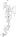
図1は、本発明の全体構成図である。ガスタービン1と、前記ガスタービン1の機械エネルギーを電気エネルギーに変換する発電機2は発電機軸3で結合される。慣性回転体19は前記発電機2と一体になって回転することで、発電機軸3の軸ねじれ共振周波数を変更するための慣性回転体19であり、発電機軸3に比べて高剛性な発電機軸18で発電機2に結合される。燃料制御装置14は前記ガスタービン1の回転力と回転数を制御し、変圧器4は前記発電機2の出力電圧を系統電圧へ変換し、変圧器5は系統電圧を電力変換器の入力電圧に変換し、変圧器4と変圧器5は系統6を介して接続される。電力変換器7は前記変圧器5から出力される電力を所望の電力に変換し、三相受電交流を整流するダイオードブリッジ整流回路からなるコンバータ15と、前記コンバータ出力を平滑する平滑コンデンサ17と、前記平滑コンデンサ電圧を三相交流に変換するインバータ16より構成される。電動機8は前記電力変換器が出力する電力で駆動され、被駆動装置9は前記電動機8によって駆動される。また、電動機8と被駆動装置9は電動機軸10で結合される。慣性回転体21は前記電動機8と一体になって回転することで、電動機軸10の軸ねじれ共振周波数を変更し、電動機軸10に比べて高剛性な電動機軸20で電動機8に結合される。そして、電力変換器制御装置11は前記電動機8の出力トルクや速度が所望の特性を満たすように前記電力変換器7を操作する。電力変換器出力電流検出器(以下、電流検出器12と記す)は、前記電力変換器7の出力電流を検出し出力する、電力変換器出力電圧検出器(以下、電圧検出器13と記す)は、前記電力変換器7の出力電圧を検出する。前記電流検出器12,電圧検出器13の出力信号は、電力変換器制御装置11に入力され、電力変換器制御装置11は、各種演算処理を行い、前記電力変換器7を操作する信号を出力する。
FIG. 1 is an overall configuration diagram of the present invention. A
ここで、電源側振動に関する関係式について説明する。図2はタービンと発電機間の軸ねじり振動を2マス系で表現したものであり、τGはタービントルク、τLは発電機負荷トルク、τsは軸ねじりトルク、ω1はタービン速度、ω2は発電機速度、Kはバネ定数、Dmは機械系の減衰係数、Deは電気系の減衰係数であり、単位は何れも定格点での正規化量p.u.である。また、Ta1はタービンの慣性モーメント、Ta2は発電機の慣性モーメントであり、単位は何れも秒である。図2において、Deは発電機の速度増加を減ずるトルクが、発電機に接続される負荷(制御装置含む)により、電気的に生じる程度を表現している。図2から得られる2次振動系の状態方程式より、系の特性方程式は(1)式となる。 Here, the relational expression regarding the power source side vibration will be described. Fig. 2 shows the torsional vibration between the turbine and the generator in a two-mass system, where τ G is the turbine torque, τ L is the generator load torque, τ s is the shaft torsion torque, ω 1 is the turbine speed, omega 2 the generator speed, K is the spring constant, D m is the attenuation coefficient of the mechanical system, D e is the attenuation coefficient of the electrical system, the unit is both a normalization amount p.u. at the rated point. T a1 is the moment of inertia of the turbine, T a2 is the moment of inertia of the generator, and each unit is seconds. In FIG. 2, D e is the torque to reduce the speed increase of the generator, the load connected to the generator (including the controller), expresses the degree to which the electrically generated. From the state equation of the secondary vibration system obtained from FIG. 2, the characteristic equation of the system is Equation (1).
ここで、(1)式の第4項目をゼロと置き、(2)式に示す2次式に近似すると(3),(4)式の関係が成り立つ。 Here, when the fourth item of the equation (1) is set to zero and approximated to the quadratic equation shown in the equation (2), the relationship of the equations (3) and (4) is established.
![]()
![]()
但し、(3),(4)式において、nを(5)式で定義する慣性モーメント比、Taを(6)式を満たす定格速度までの加速時間とする。 However, (3), (4) In the equation, the moment of inertia ratio that defines the n in (5), the acceleration time to rated speed that satisfies the T a (6) below.
![]()
![]()
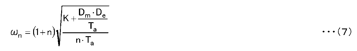
(3),(4)式より、2次系の減衰係数ζおよび2次系の固有振動角周波数ωnは、それぞれ(7),(8)式で表され、電気系減衰係数Deによりシステムの振動特性(ζ,ωn)が変化することが分かる。 From equations (3) and (4), the secondary system damping coefficient ζ and the secondary system natural vibration angular frequency ω n are expressed by formulas (7) and (8), respectively, and are expressed by the electrical system damping coefficient De. It can be seen that the vibration characteristics (ζ, ω n ) of the system change.
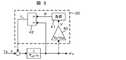
次に、電気系減衰係数の算出部30について図3を用いて説明する。図3において、破線で囲んだブロックは、図2の電気系減衰係数の算出部30に対応している。図3および以下の説明において、発電機出力および発電機負荷の有効電力をP、発電機速度をω2、発電機端子電圧をV、発電機負荷トルクをτLとし、その定格点での値をそれぞれP0,ω20,V0,τL0とし、その定格点からの変化分をそれぞれΔP,Δω2,ΔV,ΔτLとする。一方、発電機端子電圧Vは定格点近傍において界磁一定と仮定すれば発電機速度ω2に比例することから、その変換ゲインは、V0/ω20となる。これが発電機端子電圧の算出部40に対応し、(9)式で記述できる。
Next, the electric system attenuation
(9)式右辺が、V0+ΔVに対応することから、(10)式が成立する。 Since the right side of the equation (9) corresponds to V 0 + ΔV, the equation (10) is established.
また、負荷有効電力の算出部41は、負荷特性から発電機端子電圧Vに対する負荷有効電力Pを出力する。一方、発電機負荷トルクτLと発電機出力Pと、発電機速度をω2には(11)式の関係があり、発電機負荷トルクの算出部42に対応する。
The load active
(11)式右辺が、τL0+ΔτLに対応することから、(12)式が成立する。 Since the right side of the equation (11) corresponds to τ L0 + Δτ L , the equation (12) is established.
ここで一例として、負荷有効電力の算出部41において負荷が抵抗値R[p.u.]の抵抗負荷の場合を仮定する。
Here, as an example, it is assumed that the load is a resistance load having a resistance value R [pu] in the load active
このとき、P=V2/R,P0=V0 2/Rの関係が成立する。よって、この2式からRを消去して、Pについて解くと(14)式が得られる。 At this time, the relationship of P = V 2 / R and P 0 = V 0 2 / R is established. Therefore, when R is eliminated from these two equations and P is solved, equation (14) is obtained.
(14)式右辺が、P0+ΔPに対応することから、(15)式が成立する。 Since the right side of the equation (14) corresponds to P 0 + ΔP, the equation (15) is established.
さらに(10)式,(15)式を(13)式に代入すると、(16)式が得られる。 Further, when Expressions (10) and (15) are substituted into Expression (13), Expression (16) is obtained.
正規化単位では、定格値は1である。よって、(16)式右辺に、P0=ω20=τL0=1を代入すると、De=1となる。すなわち、発電機に抵抗負荷を接続すると、電気系の減衰係数Deは1になる。これに対して、例えば発電機に対して定電力負荷(ΔP=0)を接続した例を考えると、(13)式にΔP=0を代入してDe=−1となる。この場合、ネガティブダンピングとなり、発電機速度変動(振動)を助長する向きに発電機トルクが発生する。特に、機械系の減衰係数Dmが小さい場合には、前記2次系の減衰係数ζが0以下となり、発散系になることが示される。 In the normalization unit, the rated value is 1. Therefore, if P 0 = ω 20 = τ L0 = 1 is substituted into the right side of the equation (16), D e = 1. That is, when connecting a resistive load to the generator, the damping coefficient D e of the electrical system will be 1. On the other hand, for example, considering an example in which a constant power load (ΔP = 0) is connected to the generator, ΔP = 0 is substituted into the equation (13), and D e = −1. In this case, negative damping occurs, and generator torque is generated in a direction that promotes generator speed fluctuation (vibration). In particular, when the mechanical system damping coefficient D m is small, the secondary system damping coefficient ζ is 0 or less, indicating that the system is divergent.
以上は、発電機に対して、抵抗負荷または、定電力負荷を接続した場合であったが、実際のシステムでは、図1のように、変圧器,電力変換器,電動機,機械軸,被駆動装置等の特性によって電気系の減衰係数Deが決定付けられる。とりわけ、ガスタービン1および発電機2の慣性モーメントと発電機軸3のバネ定数により決まる発電機側の軸共振周波数fn[Hz]と、電動機8および電動機8で駆動される被駆動装置の慣性モーメントと電動機軸10のバネ定数により決まる電動機側の軸共振周波数fr[Hz]の関係によって電気系の減衰係数Deは大きく左右される。例えば、図4は図1に示したシステムに関する電気系の減衰係数Deを縦軸に、(17)式で定義するfnとfrの共振比hを横軸に、fnをパラメータに選んだグラフである。
The above is the case where a resistive load or a constant power load is connected to the generator, but in an actual system, as shown in FIG. 1, a transformer, a power converter, an electric motor, a mechanical shaft, and a driven damping coefficient D e of the electrical system is dictated by the characteristics of the device. In particular, the axial resonance frequency fn [Hz] on the generator side determined by the moment of inertia of the
図4のグラフから、h=1近傍、即ち、fn=frにおいて、Deが極小値をとることが分かる。また、共振比hをh≦0.9または、h≧1.1の範囲に選べば、実用上十分広範囲(2.5Hzから20Hz)のfnに関して、抵抗負荷以上のDeを確保できることが分かる。そこで、以下では、h≒1となった場合に、h≦0.9または、h≧1.1に変更する具体的手段を提示する。共振比hを構成するfrは、2慣性近似の場合、(18)式で表すことができる。(18)式において、JMは電動機8の慣性モーメント、JLは被駆動装置9の慣性モーメント、KFは電動機軸10のバネ定数である。よって、(18)式における等価的なJMを増大することにより、frを低下し、h≒1を回避することが可能である。これを実現するために、本実施形態では、電動機8を図5に示す両軸構造とし、被駆動対象と反対側の軸に、慣性回転体を装着可能な構造とした。図5に示すような電動機筺体50,電動機軸51,軸共振周波数変更用の慣性回転体52,電動機軸53からなる軸共振周波数可変構造の例から説明する。このとき、発電機側の軸共振周波数fn=10[Hz]に対して、電動機側の軸共振周波数fr=10[Hz](JM=105[kg・m2],JL=640[kg・m2],KF=356110[N・m/rad])の場合を考える。この場合、慣性モーメントが30[kg・m2]の慣性回転体52を電動機軸53に装着することで、fr=9[Hz]に変更できることが(18)式より明らかである。
From the graph of FIG. 4, h = 1 neighborhood, i.e., the fn = fr, D e is seen to take a minimum value. Further, the resonance ratio h h ≦ 0.9 or, if you choose the range of h ≧ 1.1, with respect to fn of practically sufficient wide range (20 Hz from 2.5 Hz), it can be seen that ensures resistance load more D e . Therefore, in the following, specific means for changing to h ≦ 0.9 or h ≧ 1.1 when h≈1 will be presented. Fr constituting the resonance ratio h can be expressed by the equation (18) in the case of two-inertia approximation. In the equation (18), JM is the moment of inertia of the
以上は、h≦0.9に変更するための電動機軸に対する操作であるが、図5と同様の構造を発電機軸側に持たせることで、h≧1.1に変更することも可能である。例えば、fnは、2慣性近似の場合、(19)式で表すことができる。(19)式において、Ta1はタービン1の慣性モーメント、Ta2は発電機2の慣性モーメント、Kは発電機軸3のバネ定数である。よって、(19)式における等価的なTa2を増大することにより、fnを低下し、h≧1.1への変更ができる。
The above is the operation on the motor shaft for changing to h ≦ 0.9, but it is also possible to change to h ≧ 1.1 by giving the generator shaft side the same structure as in FIG. . For example, fn can be expressed by equation (19) in the case of 2-inertia approximation. In the equation (19), T a1 is the moment of inertia of the
ところで、図1に示したシステム構築に際して、fnとfrは設計段階で既知であるとは限らず、据え付け現場で初めてfn=frに気付く場合もある。この場合、慣性回転体18,21の慣性モーメントは事前に決定できない。また、実施形態2のように、前記共振比hを、きめ細かく正確に設定したい場合がある。そこで、図6に示すように、複数枚の慣性回転体52,54等を装着可能な構造とすることで、共振比hを現場において、きめ細かく設定可能とした。
By the way, when the system shown in FIG. 1 is constructed, fn and fr are not always known at the design stage, and fn = fr may be noticed for the first time at the installation site. In this case, the moment of inertia of the inertial
〔実施形態2〕
実施形態1では、発電機と電動機が各々1台ずつ接続されていた。しかし、更に大規模なプラントに該当する本実施形態では、図7に示すように、発電機2がi台、電動機8がj台あり、それらが共通の系統に接続された構成となる。但し、図7において、符号の説明は図1の場合と共通である。この場合、発電機iの軸共振周波数をfn(i)、電動機jの軸共振周波数をfr(j)とするとき、h(i,j)=fr(j)/fn(i)で定義する共振比h(i,j)の全ての組合せについて、h(i,j)≦0.9または、h(i,j)≧1.1を満足させることで、如何なる運転状態においても、電気系減衰係数の算出部30であるDeを1以上とし、システムの安定性を確保している。一例として、発電機3台,電動機3台を共通系統に接続したシステムを考える。具体的には、各発電機軸の共振周波数がfn(1)=10[Hz],fn(2)=8[Hz],fn(3)=11[Hz]、各電動機軸の共振周波数が、fr(1)=10[Hz],fr(2)=8[Hz],fr(3)=9[Hz]の場合には、fn(1)=fr(1)=10[Hz],fn(2)=fr(2)=8[Hz]となり、h(1,1)=h(2,2)=1となる。このような場合、実施形態1で示した手段により、fr(1)を10[Hz]から9[Hz]に変更し、fr(2)を8[Hz]から7.2[Hz]に変更することで、システム全体の安定性を確保することができる。
[Embodiment 2]
In the first embodiment, one generator and one motor are connected to each other. However, in this embodiment corresponding to a larger-scale plant, as shown in FIG. 7, there are i
〔実施形態3〕
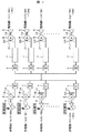
前記実施形態1,2を実施するに際しては、発電機軸および電動機軸の共振周波数fn,frを正確に推定する手段が必要となる。そこで、本実施形態では、電動機8および発電機2に対して、M系列信号または、ホワイトノイズ等の広帯域周波数の加振トルク印加手段を提供する。図8において、加振トルクの印加先を発電機または電動機に切り替えるスイッチである切換えスイッチ100または101を備え、A側接点を選択すると発電機側に加振トルクが印加され、B側接点を選択すると、電動機側に加振トルクが印加される仕組みとなっている。また、切換えスイッチ100と101は物理的に連動する構造としてもよい。一方、電力変換器制御装置11は、PWM出力を含む電流制御器102,電流偏差演算器104,M系列信号もしくは、ホワイトノイズ等の信号発生源103,発電機制御用定数107,電動機制御用定数106,発電機/電動機の制御モード切換えスイッチ105で構成される。なお、発電機制御用定数107、および、電動機制御用定数106には、発電機または電動機に固有の巻線インダクタンス,巻線抵抗,誘起電圧定数,電気定格値等が含まれる。本構成を用いれば、発電機の軸共振周波数を推定したい場合には、前記切換えスイッチ100,101をA接点側に倒した上で、制御モード切換えスイッチ105で発電機制御用定数を選択すれば、発電機軸が加振される。この状態で、別途発電機軸に取り付けた速度検出器または、加速度センサの信号を読み取り、FFT解析すれば、発電機軸の共振周波数fnを知ることができる。切換えスイッチ100,101、および制御モード切換えスイッチ105を変更すれば、同様にして、電動機軸の共振周波数frも知ることができる。
[Embodiment 3]
In carrying out the first and second embodiments, means for accurately estimating the resonance frequencies fn and fr of the generator shaft and the motor shaft are required. Therefore, in the present embodiment, an excitation torque applying means having a broadband frequency such as an M-sequence signal or white noise is provided to the
〔実施形態4〕
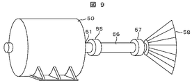
実施形態1では、電動機8または、発電機2の軸に、慣性回転体を装着することで、軸共振周波数を変化させていた。本実施形態では、図9に示す構成により、電動機と被駆動装置を接続する電動機軸56を交換可能とすることで、軸自体のバネ定数を変化させ、軸共振周波数を変化させる。具体的には、図9に示すように、軸共振周波数可変構造の電動機は、電動機筐体50と、電動機軸51と、被駆動装置58と、電動機と被駆動装置を接続する電動機軸56と、電動機軸51と電動機軸56を接続するカップリング55と、電動機軸56と被駆動装置58を接続するカップリング57を備えるとき、電動機軸56として、素材のヤング率や、軸直径の異なる物を、予め複数本準備しておき、交換することで、軸共振周波数を変化される。この操作により、電動機軸側の軸共振周波数と、発電機軸側の軸共振周波数が異なる値となる様に、調整を行う。
[Embodiment 4]
In the first embodiment, the shaft resonance frequency is changed by attaching an inertial rotating body to the shaft of the
以上の具体例では、電動機側の駆動軸を交換可能とする例を示したが、同様に、発電機側の駆動軸を交換可能とするシステムを構成しても良い。 In the above specific examples, the example in which the drive shaft on the electric motor side can be replaced has been shown. Similarly, a system in which the drive shaft on the generator side can be replaced may be configured.
〔実施形態5〕
実施形態4では、電動機と被駆動装置を接続する電動機軸56の軸径や、素材のヤング率を変化させることで、軸共振周波数を変化させていた。これに対して、本実施形態5では、図10に示す構成により、電動機と被駆動装置を接続する電動機軸56の軸長を変化させることで、駆動軸のバネ定数を変化させ、軸共振周波数を変化させる。具体的には、図10に示すように、電動機筐体50の床面に水平レール59を設置し、電動機軸56として用いる、軸長の異なる他の駆動軸を、予め複数個準備しておき、前記水平レール59で調整して、前記他の駆動軸に交換することで、軸共振周波数を変化させる。軸長変化に伴う被駆動装置58と電動機筐体50との距離の変化には、電動機筐体50を被駆動装置58に対してレール上で前後させて固定することで対応可能とする。以上の具体例では、電動機側の駆動軸を交換可能とする例を示したが、同様に、発電機を水平レール上に置いて、発電機側の駆動軸を交換可能とするシステムを構成しても良い。
[Embodiment 5]
In the fourth embodiment, the shaft resonance frequency is changed by changing the shaft diameter of the
〔実施形態6〕
実施形態1では、電動機8を両軸構造とし、被駆動対象と反対側の軸に、慣性回転体を装着することで軸共振周波数を変化させていた。これに対して、本実施形態6では、図11に示す構成により、駆動対象側の軸上に慣性回転体を装着することで、電動機の慣性モーメントを変化させ、軸共振周波数を変化させる。具体的には、図11において、電動機軸56上に装着する慣性回転体60として、慣性モーメントの異なる物を、予め複数個準備しておき、交換することで、軸共振周波数を変化させる。
[Embodiment 6]
In
1 ガスタービン
2 発電機
3,18 発電機軸
4,5 変圧器
6 系統
7 電力変換器
8 電動機
9,58 被駆動装置
10,20,51,53,56 電動機軸
11 電力変換器制御装置
12 電力変換器出力電流検出器
13 電力変換器出力電圧検出器
14 燃料制御装置
15 コンバータ
16 インバータ
17 平滑コンデンサ
19,21,52,54,60 慣性回転体
30 電気系減衰係数の算出部
40 発電機端子電圧の算出部
41 負荷有効電力の算出部
42 発電機負荷トルクの算出部
50 電動機筺体
55,57 カップリング
59 水平レール
100,101 切換えスイッチ
102 電流制御器
103 信号発生源
104 電流偏差演算器
105 制御モード切換えスイッチ
106 電動機制御用定数
107 発電機制御用定数
DESCRIPTION OF
Claims (12)
前記原動機の駆動力を前記発電機に伝える発電機軸の軸共振周波数と、前記電動機の駆動力を前記被駆動装置に伝える電動機軸の軸共振周波数とを異なる値にすることを特徴とする電動機駆動システム。 A motor, a generator that generates electric power by driving the motor, a converter that converts electric power generated by the generator into electric power of a desired frequency, and an electric motor that is driven by electric power supplied from the converter; In an electric motor drive system composed of a driven device driven by the electric motor,
An electric motor drive characterized in that the axial resonance frequency of the generator shaft that transmits the driving force of the prime mover to the generator and the axial resonance frequency of the electric motor shaft that transmits the driving force of the electric motor to the driven device have different values. system.
Priority Applications (2)
| Application Number | Priority Date | Filing Date | Title |
|---|---|---|---|
| JP2011116478A JP2012249342A (en) | 2011-05-25 | 2011-05-25 | Motor driving system and method |
| CN2012101598742A CN102801373A (en) | 2011-05-25 | 2012-05-22 | Motor driving system and method |
Applications Claiming Priority (1)
| Application Number | Priority Date | Filing Date | Title |
|---|---|---|---|
| JP2011116478A JP2012249342A (en) | 2011-05-25 | 2011-05-25 | Motor driving system and method |
Publications (1)
| Publication Number | Publication Date |
|---|---|
| JP2012249342A true JP2012249342A (en) | 2012-12-13 |
Family
ID=47200364
Family Applications (1)
| Application Number | Title | Priority Date | Filing Date |
|---|---|---|---|
| JP2011116478A Pending JP2012249342A (en) | 2011-05-25 | 2011-05-25 | Motor driving system and method |
Country Status (2)
| Country | Link |
|---|---|
| JP (1) | JP2012249342A (en) |
| CN (1) | CN102801373A (en) |
Families Citing this family (2)
| Publication number | Priority date | Publication date | Assignee | Title |
|---|---|---|---|---|
| CN117606794B (en) * | 2023-11-28 | 2026-02-10 | 北京理工大学 | A dual-motor torsional vibration active control test platform |
| CN121727299B (en) * | 2026-02-12 | 2026-04-17 | 福建铨一电源科技有限公司 | A permanent magnet generator with fault detection function |
Citations (17)
| Publication number | Priority date | Publication date | Assignee | Title |
|---|---|---|---|---|
| JPH05284704A (en) * | 1992-03-31 | 1993-10-29 | Toshiba Corp | Brushless rotating electric machine |
| JPH06253564A (en) * | 1993-02-25 | 1994-09-09 | Ckd Corp | Constant value setting method for motor resonance frequency damping filter |
| JPH07129034A (en) * | 1993-09-10 | 1995-05-19 | Konica Corp | Photoreceptor driving device and method for controlling the same |
| JPH07152429A (en) * | 1993-11-29 | 1995-06-16 | Mitsubishi Heavy Ind Ltd | Parameter identifying device |
| JPH0837800A (en) * | 1994-07-26 | 1996-02-06 | Shinko Electric Co Ltd | Stable power supply device for closed circuit power system |
| JPH08124287A (en) * | 1994-10-28 | 1996-05-17 | Internatl Business Mach Corp <Ibm> | Assembly structure of disk drive,disk drive and assembly method of disk drive |
| JPH10288191A (en) * | 1997-04-16 | 1998-10-27 | Daikin Ind Ltd | pump |
| JP2000152555A (en) * | 1998-11-05 | 2000-05-30 | Toshiba Fa Syst Eng Corp | Power generator |
| JP2001045779A (en) * | 1999-08-02 | 2001-02-16 | Meidensha Corp | Variable speed device |
| JP2001134139A (en) * | 1999-11-09 | 2001-05-18 | Ricoh Co Ltd | Rotary drive device and image reading device |
| JP2003111354A (en) * | 2001-10-02 | 2003-04-11 | Hitachi Ltd | Alternator with vacuum pump |
| JP2004114713A (en) * | 2002-09-24 | 2004-04-15 | Jatco Ltd | Vehicle drive system |
| JP2005312261A (en) * | 2004-04-26 | 2005-11-04 | Toshiba Mitsubishi-Electric Industrial System Corp | Method for determining combined stability of power generation equipment and power converter |
| JP2006315662A (en) * | 2005-04-12 | 2006-11-24 | Nissan Motor Co Ltd | Hybrid drive device for vehicle |
| JP2007185014A (en) * | 2006-01-05 | 2007-07-19 | Matsushita Electric Ind Co Ltd | Motor control device control parameter calculation method, calculation program, and motor control device |
| JP2010283905A (en) * | 2009-06-02 | 2010-12-16 | Hitachi Ltd | Power converter, power conversion system, and control method for power converter |
| JP2010283904A (en) * | 2009-06-02 | 2010-12-16 | Hitachi Ltd | Power converter, power conversion system, and control method for power converter |
Family Cites Families (4)
| Publication number | Priority date | Publication date | Assignee | Title |
|---|---|---|---|---|
| JP4273560B2 (en) * | 1999-03-23 | 2009-06-03 | パナソニック株式会社 | Motor control device |
| US7173399B2 (en) * | 2005-04-19 | 2007-02-06 | General Electric Company | Integrated torsional mode damping system and method |
| FI121644B (en) * | 2008-03-03 | 2011-02-15 | Waertsilae Finland Oy | Arrangement for vibration damping |
| US8384338B2 (en) * | 2009-01-30 | 2013-02-26 | Eaton Corporation | System and method for determining stator winding resistance in an AC motor using motor drives |
-
2011
- 2011-05-25 JP JP2011116478A patent/JP2012249342A/en active Pending
-
2012
- 2012-05-22 CN CN2012101598742A patent/CN102801373A/en active Pending
Patent Citations (17)
| Publication number | Priority date | Publication date | Assignee | Title |
|---|---|---|---|---|
| JPH05284704A (en) * | 1992-03-31 | 1993-10-29 | Toshiba Corp | Brushless rotating electric machine |
| JPH06253564A (en) * | 1993-02-25 | 1994-09-09 | Ckd Corp | Constant value setting method for motor resonance frequency damping filter |
| JPH07129034A (en) * | 1993-09-10 | 1995-05-19 | Konica Corp | Photoreceptor driving device and method for controlling the same |
| JPH07152429A (en) * | 1993-11-29 | 1995-06-16 | Mitsubishi Heavy Ind Ltd | Parameter identifying device |
| JPH0837800A (en) * | 1994-07-26 | 1996-02-06 | Shinko Electric Co Ltd | Stable power supply device for closed circuit power system |
| JPH08124287A (en) * | 1994-10-28 | 1996-05-17 | Internatl Business Mach Corp <Ibm> | Assembly structure of disk drive,disk drive and assembly method of disk drive |
| JPH10288191A (en) * | 1997-04-16 | 1998-10-27 | Daikin Ind Ltd | pump |
| JP2000152555A (en) * | 1998-11-05 | 2000-05-30 | Toshiba Fa Syst Eng Corp | Power generator |
| JP2001045779A (en) * | 1999-08-02 | 2001-02-16 | Meidensha Corp | Variable speed device |
| JP2001134139A (en) * | 1999-11-09 | 2001-05-18 | Ricoh Co Ltd | Rotary drive device and image reading device |
| JP2003111354A (en) * | 2001-10-02 | 2003-04-11 | Hitachi Ltd | Alternator with vacuum pump |
| JP2004114713A (en) * | 2002-09-24 | 2004-04-15 | Jatco Ltd | Vehicle drive system |
| JP2005312261A (en) * | 2004-04-26 | 2005-11-04 | Toshiba Mitsubishi-Electric Industrial System Corp | Method for determining combined stability of power generation equipment and power converter |
| JP2006315662A (en) * | 2005-04-12 | 2006-11-24 | Nissan Motor Co Ltd | Hybrid drive device for vehicle |
| JP2007185014A (en) * | 2006-01-05 | 2007-07-19 | Matsushita Electric Ind Co Ltd | Motor control device control parameter calculation method, calculation program, and motor control device |
| JP2010283905A (en) * | 2009-06-02 | 2010-12-16 | Hitachi Ltd | Power converter, power conversion system, and control method for power converter |
| JP2010283904A (en) * | 2009-06-02 | 2010-12-16 | Hitachi Ltd | Power converter, power conversion system, and control method for power converter |
Also Published As
| Publication number | Publication date |
|---|---|
| CN102801373A (en) | 2012-11-28 |
Similar Documents
| Publication | Publication Date | Title |
|---|---|---|
| EP2020744B1 (en) | Active damping for synchronous generator torsional oscillations | |
| EP3048333A1 (en) | Method and system for damping torsional oscillations | |
| EP2933905B1 (en) | System and method for detection of motor vibration | |
| EP3454469B1 (en) | Torque ripple reduction for a generator and wind turbine including the same | |
| US9160266B2 (en) | Method and device for damping torsional oscillations | |
| EP2487784B1 (en) | Method and system for controlling a DC link voltage of a power converter connecting an electric generator of a wind turbine with a power grid | |
| US20120139243A1 (en) | Method and system for resonance dampening in wind turbines | |
| JP2008537470A (en) | Integrated torsional mode damping system and method | |
| US20160156297A1 (en) | Motor drive system, motor control apparatus and motor control method | |
| EP2161821A1 (en) | Magnetically geared generator | |
| JP2013527737A (en) | Rectifier and inverter based torsional mode damping system and method | |
| JP5393238B2 (en) | Electric motor drive system, electric motor control device, and electric motor drive method | |
| CN113114083A (en) | Torsional mode damping controller | |
| JP2013198221A (en) | Electric motor controller | |
| JP2013524752A (en) | Rectifier-based torsional mode damping system and method | |
| RU2559200C2 (en) | System and method for torsional oscillation damping without usage of sensors | |
| US9337765B2 (en) | Method for operating an electrical machine | |
| JP6632633B2 (en) | Controller for asynchronous machine and method of operating asynchronous machine | |
| JP2015116092A (en) | Electric vehicle | |
| JP2012249342A (en) | Motor driving system and method | |
| KR20160119260A (en) | Drivetrain testing system | |
| US20230016864A1 (en) | Method, an Arrangement and a Frequency Converter for Identification of Torsional Natural Frequencies of a Drivetrain System | |
| CN110703030A (en) | Electromagnetic compatibility testing system for motor in on-load working state | |
| US12422336B2 (en) | Method, an arrangement and a frequency converter for controlling vibration of an electric machine | |
| US11545921B2 (en) | Active damping of mechanical drivetrain oscillations using generator voltage regulator |
Legal Events
| Date | Code | Title | Description |
|---|---|---|---|
| A621 | Written request for application examination |
Free format text: JAPANESE INTERMEDIATE CODE: A621 Effective date: 20130313 |
|
| A977 | Report on retrieval |
Free format text: JAPANESE INTERMEDIATE CODE: A971007 Effective date: 20130704 |
|
| A131 | Notification of reasons for refusal |
Free format text: JAPANESE INTERMEDIATE CODE: A131 Effective date: 20130717 |
|
| A02 | Decision of refusal |
Free format text: JAPANESE INTERMEDIATE CODE: A02 Effective date: 20131203 |