JP2012249077A - Folding type electronic device - Google Patents
Folding type electronic device Download PDFInfo
- Publication number
- JP2012249077A JP2012249077A JP2011119177A JP2011119177A JP2012249077A JP 2012249077 A JP2012249077 A JP 2012249077A JP 2011119177 A JP2011119177 A JP 2011119177A JP 2011119177 A JP2011119177 A JP 2011119177A JP 2012249077 A JP2012249077 A JP 2012249077A
- Authority
- JP
- Japan
- Prior art keywords
- casing
- hinge
- housing
- connecting member
- housings
- Prior art date
- Legal status (The legal status is an assumption and is not a legal conclusion. Google has not performed a legal analysis and makes no representation as to the accuracy of the status listed.)
- Granted
Links
Images


Landscapes
- Telephone Set Structure (AREA)
Abstract
Description
本発明は、一対の筐体を互いに開閉可能に連結して構成される折り畳み式電子機器に関するものである。 The present invention relates to a foldable electronic apparatus configured by connecting a pair of housings so that they can be opened and closed.
従来、一対の筐体を互いに開閉可能に連結して構成されている折り畳み式電子機器においては、開閉操作の対象となる一方の筐体の両面にメインディスプレイとサブディスプレイを配備して、該筐体の閉じ状態と開き状態でメインディスプレイとサブディスプレイを使い分けることが行なわれる(特許文献1)。 2. Description of the Related Art Conventionally, in a foldable electronic device configured by connecting a pair of casings so as to be openable and closable, a main display and a sub-display are provided on both sides of one casing to be opened and closed. The main display and the sub-display are properly used depending on whether the body is closed or open (Patent Document 1).
この様な折り畳み式電子機器においては、前記一方の筐体の開き状態ではメインディスプレイとサブディスプレイの両方が露出するものの、両ディスプレイは互いに反対方向を向いているので、両ディスプレイに跨って1つの画像を表示することは出来ない。 In such a foldable electronic device, both the main display and the sub display are exposed in the opened state of the one casing, but both displays are directed in opposite directions. The image cannot be displayed.
そこで、2軸ヒンジ機構を介して一対の筐体を互いに開閉可能に連結することが考えられる(特許文献2)。
例えば図19(a)(b)に示す折り畳み式電子機器においては、互いに平行な2本のヒンジ軸a1、a2を有する平行2軸ヒンジ機構(92)を介して、第1筐体(9)と第2筐体(91)とが互いに連結され、第1筐体(9)の内面には第1ディスプレイ(93)が配備されると共に、第2筐体(91)の内面には第2ディスプレイ(94)が配備され、図19(a)に示す全閉状態と図19(b)に示す全開状態との間で開閉が可能である。
Therefore, it is conceivable to connect a pair of housings so as to be openable and closable via a biaxial hinge mechanism (Patent Document 2).
For example, in the foldable electronic device shown in FIGS. 19 (a) and 19 (b), the first housing (9) is provided via a parallel biaxial hinge mechanism (92) having two hinge axes a1 and a2 parallel to each other. And the second casing (91) are connected to each other, and a first display (93) is provided on the inner surface of the first casing (9), and a second display on the inner surface of the second casing (91). A display (94) is provided and can be opened and closed between a fully closed state shown in FIG. 19 (a) and a fully opened state shown in FIG. 19 (b).
該折り畳み式電子機器によれば、第1筐体(9)と第2筐体(91)とが平行2軸ヒンジ機構(92)を介して互いに連結されているので、2本のヒンジ軸a1、a2間の距離に必要な余裕を与えることによって、第1筐体(9)のヒンジ軸a1側の端部と第2筐体(91)のヒンジ軸a2側の端部とを互いに干渉させることなく、図19(a)に示す全閉状態から図19(b)に示す全開状態へ、そして図19(b)に示す全開状態から図19(a)に示す全閉状態へ移行させることが出来る。 According to the foldable electronic device, since the first housing (9) and the second housing (91) are connected to each other via the parallel biaxial hinge mechanism (92), the two hinge shafts a1. , A necessary margin is given to the distance between a2 to cause the end of the first housing (9) on the hinge shaft a1 side and the end of the second housing (91) on the hinge shaft a2 side to interfere with each other. Without transition from the fully closed state shown in FIG. 19 (a) to the fully opened state shown in FIG. 19 (b), and from the fully opened state shown in FIG. 19 (b) to the fully closed state shown in FIG. 19 (a). I can do it.
この様な折り畳み式電子機器によれば、図19(b)に示す全開状態で、両ディスプレイ(93)(94)の画面を同一平面上に揃えて、これら2つの画面によって1つの大きな画面を形成することが出来る。 According to such a foldable electronic device, the screens of both displays (93) and (94) are aligned on the same plane in the fully opened state shown in FIG. 19 (b), and one large screen is formed by these two screens. Can be formed.
しかしながら、図19に示す折り畳み式電子機器においては、図19(b)に示す全開状態で第1筐体(9)と第2筐体(91)の間にギャップBが形成されるため、第1ディスプレイ(93)の画面と第2ディスプレイ(94)の画面との間にも、両筐体(9)(91)間にギャップBよりも大きな間隔Aが形成されることになり、両ディスプレイ(93)(94)の画面に跨って1つの画像を表示したとき、その画像に大きな途切れが生じて、画像の連続性に問題が生じることになる。
However, in the foldable electronic device shown in FIG. 19, the gap B is formed between the first housing (9) and the second housing (91) in the fully opened state shown in FIG. A gap A larger than the gap B is formed between the
そこで本発明の目的は、一対の筐体を互いに開閉可能に連結して構成される折り畳み式電子機器において、両筐体の全開状態と全閉状態の間の移行をスムーズに行なうと共に、全開状態で両筐体を同一平面上で互いに最接近させることが出来る折り畳み式電子機器を提供することである。 Therefore, an object of the present invention is to provide a foldable electronic device configured by connecting a pair of housings so that they can be opened and closed, and smoothly transition between the fully open state and the fully closed state of both housings. The present invention is to provide a foldable electronic device that can bring both housings closest to each other on the same plane.
本発明に係る折り畳み式電子機器においては、一対の筐体が連結機構を介して互いに連結され、両筐体の表面を互いに対向させた全閉状態と、両筐体の表面を同一方向へ向けて並べた全開状態との間で、開閉が可能である。 In the foldable electronic device according to the present invention, a pair of housings are connected to each other via a connecting mechanism, and the surfaces of both housings face each other, and the surfaces of both housings face the same direction. It can be opened and closed between the fully open states arranged side by side.
前記連結機構は、互いに平行な2本のヒンジ軸を有する2軸ヒンジ機構と、2軸ヒンジ機構の2本のヒンジ軸と直交する面に沿って回動が可能な連結部材とを有し、前記2軸ヒンジ機構の一方のヒンジ軸が一方の筐体に枢支されると共に、他方のヒンジ軸が前記連結部材の一方の端部に枢支され、前記連結部材の他方の端部は、他方の筐体に対し、前記2本のヒンジ軸と平行な軸回りの回転と、前記他方の筐体を前記2本のヒンジ軸に対して接近離間させる方向の往復移動とが可能に連結されている。 The coupling mechanism includes a biaxial hinge mechanism having two hinge shafts parallel to each other, and a coupling member capable of rotating along a plane orthogonal to the two hinge shafts of the biaxial hinge mechanism, One hinge shaft of the biaxial hinge mechanism is pivotally supported by one housing, and the other hinge shaft is pivotally supported by one end portion of the connecting member, and the other end portion of the connecting member is The other casing is connected to be able to rotate around an axis parallel to the two hinge axes and to reciprocate in a direction to move the other casing closer to and away from the two hinge axes. ing.
又、前記連結部材と前記他方の筐体との間には、前記軸回りに前記他方の筐体を前記一方の筐体に対する開き方向と同じ回転方向に回転させる付勢力と、前記他方の筐体を前記2本のヒンジ軸に接近させる方向の付勢力とを発揮する付勢手段が介在している。 Further, between the connecting member and the other casing, an urging force for rotating the other casing around the axis in the same rotation direction as the opening direction with respect to the one casing, and the other casing. An urging means for exerting an urging force in a direction in which the body approaches the two hinge shafts is interposed.
上記折り畳み式電子機器においては、一方の筐体に対して他方の筐体を0°の開き角度(全閉状態)から90°の開き角度へ向けて開く過程(前半開き過程)で、両筐体のヒンジ軸側の端部が互いに当接し、付勢手段による付勢によって両筐体の端部どうしが突っ張り合うことになる。この状態から更に他方の筐体を開くと、両筐体の端部どうしが互いに突っ張り合ったまま、他方の筐体が一方の筐体との位置関係で決まる一定の軌跡を描いて回動し、この他方の筐体の回動に伴って、他方の筐体の回動よりも進んだ位相で連結部材が回動する。この様にして、他方の筐体と連結部材との間に相対移動が生じて、付勢手段が徐々に弾性変形する。 In the above foldable electronic device, in the process of opening the other casing with respect to one casing from the opening angle of 0 ° (fully closed state) to the opening angle of 90 ° (first opening step), The ends of the body on the hinge shaft side come into contact with each other, and the end portions of the two casings are stuck to each other by the urging force by the urging means. When the other housing is further opened from this state, the other housing rotates while drawing a fixed trajectory determined by the positional relationship with the other housing, with the ends of both housings sticking to each other. As the other casing is rotated, the connecting member is rotated at a phase more advanced than that of the other casing. In this way, relative movement occurs between the other casing and the connecting member, and the biasing means is gradually elastically deformed.
その後、他方の筐体を90°の開き角度を越えて全開状態へ向けて開いていく過程(後半開き過程)では、付勢手段による付勢によって、両筐体の端部どうしが互いに突っ張り合ったまま、他方の筐体は一方の筐体との位置関係で決まる一定の軌跡を描いて回動し、この他方の筐体の回動に伴って、他方の筐体の回動よりも位相が遅れて連結部材が回動する。この様にして、前半開き過程での他方の筐体と連結部材との間の相対移動とは逆向きの相対移動が生じ、最終的に例えば180°の開き角度(全開状態)では、他方の筐体が連結部材に対して最接近し、両筐体の表面が略同一面上に揃うことになる。 After that, in the process of opening the other casing to the fully open state beyond the opening angle of 90 ° (the second half opening process), the end portions of both casings stick to each other by the biasing means. The other casing rotates while drawing a fixed trajectory determined by the positional relationship with the other casing, and the phase of the other casing is rotated with the rotation of the other casing. The connection member rotates with a delay. In this way, a relative movement opposite to the relative movement between the other casing and the connecting member in the first half opening process occurs, and finally, for example, at an opening angle of 180 ° (fully opened state) The housing is closest to the connecting member, and the surfaces of both housings are aligned on substantially the same plane.
本発明に係る折り畳み式電子機器によれば、全開状態と全閉状態をデフォルト状態として開閉過程で両筐体の端部どうしが突っ張り合うことによるデフォルト状態からのずれを、両筐体間の自由度によって吸収し、全開状態と全閉状態では、付勢手段による付勢によってデフォルト状態に復帰させることが出来るので、全開状態と全閉状態の間の移行をスムーズに行なうと共に、全開状態で両筐体を同一平面上で互いに最接近させることが出来る。 According to the foldable electronic device of the present invention, the default state between the fully opened state and the fully closed state is set as the default state, and the deviation from the default state due to the end portions of the two housings struggling in the opening and closing process can be freely performed between the two housings. In the fully open state and the fully closed state, it can be restored to the default state by urging by the urging means, so that the transition between the fully opened state and the fully closed state can be performed smoothly and both in the fully opened state. The casings can be brought closest to each other on the same plane.
以下、本発明の実施の形態につき、図面に沿って具体的に説明する。
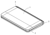
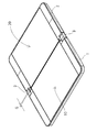
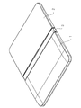
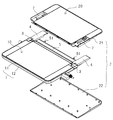
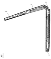
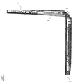
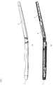
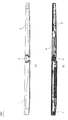
本発明の一実施形態である折り畳み式電子機器は、図1〜図4に示す如く、第1筐体(1)と第2筐体(2)とを開閉可能に連結して構成され、図1及び図2に示す全閉状態と図3及び図4に示す全開状態との間で開閉が可能である。
図3に示す全開状態では、第1筐体(1)の内面に設けた画面(10)と第2筐体(2)の内面に設けた画面(20)とが同一平面上に揃うことになる。
Hereinafter, embodiments of the present invention will be specifically described with reference to the drawings.
A foldable electronic device according to an embodiment of the present invention is configured by connecting a first housing (1) and a second housing (2) so as to be openable and closable as shown in FIGS. Opening and closing is possible between the fully closed state shown in FIGS. 1 and 2 and the fully open state shown in FIGS. 3 and 4.
In the fully opened state shown in FIG. 3, the screen (10) provided on the inner surface of the first housing (1) and the screen (20) provided on the inner surface of the second housing (2) are aligned on the same plane. Become.
尚、第1筐体(1)と第2筐体(2)の間には、第2筐体(2)を全閉状態で受け止める受け止め手段(図示省略)が設けられている。 A receiving means (not shown) for receiving the second casing (2) in the fully closed state is provided between the first casing (1) and the second casing (2).
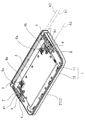
図5に示す如く、第1筐体(1)と第2筐体(2)との間には、左右一対の2軸ヒンジユニット(3)(3)と、左右一対の連結部材(4)(4)とが介在し、両連結部材(4)(4)は帯板部材(5)によって互いに連結されている。2軸ヒンジユニット(3)は互いに平行な2本のヒンジ軸A1、A2を有している。
そして、2軸ヒンジユニット(3)の一方のヒンジ軸A1が第1筐体(1)の後方端部に枢支(一軸を中心として回転可能に支持)されると共に、2軸ヒンジユニット(3)の他方のヒンジ軸A2が連結部材(4)の一方の端部に枢支されている。
As shown in FIG. 5, a pair of left and right biaxial hinge units (3) and (3) and a pair of left and right connecting members (4) are provided between the first casing (1) and the second casing (2). (4) is interposed, and both the connecting members (4) and (4) are connected to each other by the strip plate member (5). The biaxial hinge unit (3) has two hinge axes A1 and A2 which are parallel to each other.
One hinge axis A1 of the biaxial hinge unit (3) is pivotally supported (supported so as to be rotatable about one axis) at the rear end of the first housing (1), and the biaxial hinge unit (3 The other hinge shaft A2 is pivotally supported at one end of the connecting member (4).
又、連結部材(4)の他方の端部には、前記ヒンジ軸A1、A2と平行な軸A3を有する軸部材(8)が突設され、該軸部材(8)は、第2筐体(2)の前後方向の略中央部に形成された長孔状の軸受け(81)に係合して、連結部材(4)に対する第2筐体(2)の前記軸A3回りの回転と、2軸ヒンジユニット(3)に対する接近離間方向の往復移動とが許容されている。 A shaft member (8) having an axis A3 parallel to the hinge shafts A1 and A2 protrudes from the other end of the connecting member (4). The shaft member (8) is connected to the second casing. (2) engaging with a long hole-shaped bearing (81) formed substantially in the center in the front-rear direction, and rotating the second housing (2) about the axis A3 relative to the connecting member (4); Reciprocating movement in the approaching / separating direction with respect to the biaxial hinge unit (3) is allowed.
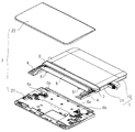
図6及び図7に示す如く、第1筐体(1)はフロントキャビネット(11)とバックキャビネット(12)とを互いに接合して構成され、第2筐体(2)はフロントキャビネット(21)とバックキャビネット(22)とを互いに接合して構成されている。 As shown in FIGS. 6 and 7, the first casing (1) is configured by joining a front cabinet (11) and a back cabinet (12) to each other, and the second casing (2) is a front cabinet (21). And the back cabinet (22) are joined together.
図7の如く、帯板部材(5)には、連結部材(4)(4)の突出方向へ左右一対の舌片(51)(51)が突設され、両舌片(51)(51)と第2筐体(2)のフロントキャビネット(21)との間には、それぞれトーションバネからなる左右一対の第1スプリング(6)(6)が介在している。
尚、図5及び図7には、第1スプリング(6)の自由状態(6a)と、第1スプリング(6)が帯板部材(5)の舌片(51)と第2筐体(2)のフロントキャビネット(21)との間に圧縮されて介在している圧縮状態(6b)とを、それぞれ実線で描いている。
As shown in FIG. 7, the strip member (5) is provided with a pair of left and right tongues (51) (51) projecting in the protruding direction of the connecting members (4) (4). A pair of left and right first springs (6) and (6) each consisting of a torsion spring are interposed between the front cabinet (21) of the second casing (2).
5 and 7, the free state (6a) of the first spring (6) and the first spring (6) are the tongue piece (51) of the strip plate member (5) and the second casing (2). ) In a compressed state (6b) which is compressed and interposed between the front cabinet (21).
又、図6の如く第2筐体(2)のフロントキャビネット(21)には、左右一対のコイルバネからなる第2スプリング(7)(7)が設置され、各第2スプリング(7)の一方の端部が第2筐体(2)のフロントキャビネット(21)に連結されると共に、各第2スプリング(7)の他方の端部が各連結部材(4)に連結されている(図7参照)。 Further, as shown in FIG. 6, the front cabinet (21) of the second casing (2) is provided with second springs (7) and (7) comprising a pair of left and right coil springs, and one of the second springs (7). Is connected to the front cabinet (21) of the second casing (2), and the other end of each second spring (7) is connected to each connecting member (4) (FIG. 7). reference).
この結果、図8(a)(b)に模式的に示す様に、第1スプリング(6)と第2スプリング(7)が第2筐体(2)を連結部材(4)に対して付勢し、第1スプリング(6)によって、軸A3回りに第2筐体(2)の開き方向と同じ回転方向(時計方向)に回転させる付勢力Tが得られると共に、第2スプリング(7)によって第2筐体(2)をヒンジ軸A2に接近させる方向の付勢力Fが得られる。
As a result, as schematically shown in FIGS. 8A and 8B, the
従って、図8(a)に示すデフォルト状態から、図8(b)の如く連結部材(4)に対して第2筐体(2)がヒンジ軸A2から離間すると共に、軸A3回りに閉じ方向に回転して、第1スプリング(6)と第2スプリング(7)が弾性変形したとき、第1スプリング(6)の付勢力Tと第2スプリング(7)の付勢力Fによって、第2筐体(2)は、図8(a)に示すデフォルト状態へ向けて付勢されることになる。
Accordingly, from the default state shown in FIG. 8A, the
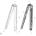
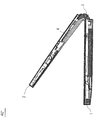
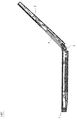
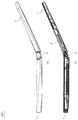
図9〜図18は、第1筐体(1)に対する第2筐体(2)の全閉状態から全開状態に至る一連の開き動作を示している。
図9に示す全閉状態では、図8に示す第1スプリング(6)と第2スプリング(7)が僅かに弾性変形しており、第1スプリング(6)と第2スプリング(7)の付勢力によって、第2筐体(2)の内面が第1筐体(1)の内面と僅かな隙間をおいて対向すると共に、第2筐体(2)が2軸ヒンジユニット(3)側に移動したデフォルト状態が設定されている。
9 to 18 show a series of opening operations from the fully closed state to the fully open state of the second housing (2) with respect to the first housing (1).
In the fully closed state shown in FIG. 9, the first spring (6) and the second spring (7) shown in FIG. 8 are slightly elastically deformed, and the first spring (6) and the second spring (7) are attached. Due to the force, the inner surface of the second housing (2) faces the inner surface of the first housing (1) with a slight gap, and the second housing (2) faces the biaxial hinge unit (3) side. Moved default state is set.
この状態から、第2筐体(2)を開くと、図10〜図13に示す前半開き過程では、第2筐体(2)の2軸ヒンジユニット(3)側の端部が第1筐体(1)の端部と当接し、第1スプリング(6)及び第2スプリング(7)の付勢によって両筐体(1)(2)の端部どうしが突っ張り合った状態で、第2筐体(2)が第1筐体(1)との位置関係で決まる一定の軌跡を描いて回動する。
この第2筐体(2)の回動に伴って、連結部材(4)は第2筐体(2)よりも僅かに進んだ位相で第2筐体(2)と同一方向に回動する。
When the second casing (2) is opened from this state, the end of the second casing (2) on the two-axis hinge unit (3) side is the first casing in the first half opening process shown in FIGS. The second end is in contact with the end of the body (1) and the ends of the two casings (1) and (2) are urged against each other by the bias of the first spring (6) and the second spring (7). The casing (2) rotates while drawing a fixed locus determined by the positional relationship with the first casing (1).
As the second casing (2) rotates, the connecting member (4) rotates in the same direction as the second casing (2) at a phase slightly advanced from the second casing (2). .
この過程で、第1筐体(1)と第2筐体(2)の突っ張り合いは徐々に強まり、第1スプリング(6)が圧縮されると共に、第2スプリング(7)が伸張されることになる。
この様にして、第2筐体(2)と連結部材(4)との間に相対移動が生じて、第1スプリング(6)と第2スプリング(7)が徐々に弾性変形する。
In this process, the tension between the first casing (1) and the second casing (2) gradually increases, and the first spring (6) is compressed and the second spring (7) is expanded. become.
In this way, relative movement occurs between the second housing (2) and the connecting member (4), and the first spring (6) and the second spring (7) are gradually elastically deformed.
その後、図14〜図18に示す如く、第2筐体(2)を90°の開き角度を越えて全開状態へ向けて開いていく後半開き過程では、第1スプリング(6)及び第2スプリング(7)の付勢によって、両筐体(1)(2)の端部どうしが互いに突っ張り合ったまま、第2筐体(2)は第1筐体(1)との位置関係で決まる一定の軌跡を描いて回動する。
この第2筐体(2)の回動に伴って、連結部材(4)は第2筐体(2)よりも僅かに遅れた位相で第2筐体(2)と同一方向に回動する。
Thereafter, as shown in FIGS. 14 to 18, in the second half opening process in which the second casing (2) is opened to the fully opened state beyond the opening angle of 90 °, the first spring (6) and the second spring (2) are opened. Due to the urging of (7), the second casing (2) is fixed depending on the positional relationship with the first casing (1) while the ends of both casings (1) and (2) are stuck against each other. Draw a trajectory and turn.
As the second casing (2) rotates, the connecting member (4) rotates in the same direction as the second casing (2) with a phase slightly delayed from the second casing (2). .
この過程で、第1筐体(1)と第2筐体(2)の突っ張り合いが徐々に弱まり、第1スプリング(6)が伸張方向に弾性復帰すると共に、第2スプリング(7)が収縮方向に弾性復帰する。
これによって、第2筐体(2)は2軸ヒンジユニット(3)のヒンジ軸A2に対して徐々に接近し、最終的に図18に示す180°の開き角度(全開状態)では、第2筐体(2)が連結部材(4)に対して最接近し、両筐体(1)(2)の表面が同一平面上に揃うことになる。
During this process, the tension between the first casing (1) and the second casing (2) gradually weakens, the first spring (6) is elastically restored in the extension direction, and the second spring (7) is contracted. Returns elastically in the direction.
As a result, the second housing (2) gradually approaches the hinge axis A2 of the biaxial hinge unit (3), and finally at the 180 ° opening angle (fully opened state) shown in FIG. The casing (2) comes closest to the connecting member (4), and the surfaces of both casings (1) and (2) are aligned on the same plane.
第1筐体(1)及び第2筐体(2)を全開状態から全閉状態まで閉じる過程の動作は、上述した開き過程における一連の動作とは逆に推移する。 The operation in the process of closing the first housing (1) and the second housing (2) from the fully opened state to the fully closed state changes in the opposite direction to the series of operations in the opening process described above.
上記折り畳み式電子機器においては、図1に示す全閉状態で、第2筐体(2)の内面を第1筐体(1)の内面と僅かな隙間をおいて対向させると共に、第2筐体(2)を2軸ヒンジユニット(3)に対して最接近させたデフォルト状態が設定される一方、図3に示す全開状態では、第1筐体(1)の内面と第2筐体(2)の内面を同一平面上に揃えると共に、第2筐体(2)を2軸ヒンジユニット(3)に対して最接近させたデフォルト状態が設定される。
従って、図1に示す全閉状態では、第2筐体(2)を第1筐体(1)上に正確に重ね合わせることが出来、図3に示す全開状態では、第1筐体(1)の画面(10)と第2筐体(2)の画面(10)とを僅かな間隔Gをおいて接近させて、両画面(10)(20)に跨って1つの大きな画像を表示したときの画像の連続性を良好なものとすることが出来る。
In the foldable electronic device, in the fully closed state shown in FIG. 1, the inner surface of the second housing (2) is opposed to the inner surface of the first housing (1) with a slight gap, and the second housing While the default state in which the body (2) is closest to the biaxial hinge unit (3) is set, in the fully open state shown in FIG. 3, the inner surface of the first housing (1) and the second housing ( A default state in which the inner surface of 2) is aligned on the same plane and the second casing (2) is closest to the biaxial hinge unit (3) is set.
Therefore, in the fully closed state shown in FIG. 1, the second housing (2) can be accurately superimposed on the first housing (1). In the fully opened state shown in FIG. The screen (10) of the second casing (2) and the screen (10) of the second housing (2) are brought close to each other with a slight gap G, and one large image is displayed across the screens (10) and (20). It is possible to improve the continuity of the image at the time.
更に、図10〜図17に示す開閉過程では、第1筐体(1)に対する連結部材(4)の回動と、連結部材(4)に対する第2筐体(2)の回転及び往復移動とによって、デフォルト状態からのずれを吸収すると共に、第1スプリング(6)及び第2スプリング(7)によってデフォルト状態へ戻す付勢力を発生させるので、両筐体(1)(2)の端部どうしを無理なく当接させてスムーズな開閉動作を実現することが出来る。 Further, in the opening and closing process shown in FIGS. 10 to 17, the rotation of the connecting member (4) with respect to the first housing (1), and the rotation and reciprocation of the second housing (2) with respect to the connecting member (4). As a result, the deviation from the default state is absorbed and the urging force to return to the default state is generated by the first spring (6) and the second spring (7), so the ends of the two cases (1) and (2) are connected to each other. It is possible to achieve a smooth opening and closing operation by making contact with each other.
尚、本発明の各部構成は上記実施の形態に限らず、特許請求の範囲に記載の技術的範囲内で種々の変形が可能である。例えば、第1筐体(1)と第2筐体(2)とを入れ替えた構成、即ち第2筐体(2)に2軸ヒンジユニット(3)を介して連結部材(4)を連結し、該連結部材(4)に第1筐体(1)を連結した構成に本発明を実施することも可能である。 In addition, each part structure of this invention is not restricted to the said embodiment, A various deformation | transformation is possible within the technical scope as described in a claim. For example, the first casing (1) and the second casing (2) are interchanged, that is, the connecting member (4) is connected to the second casing (2) via the biaxial hinge unit (3). The present invention can also be implemented in a configuration in which the first casing (1) is connected to the connecting member (4).
(1) 第1筐体
(11) フロントキャビネット
(12) バックキャビネット
(2) 第2筐体
(21) フロントキャビネット
(22) バックキャビネット
(3) 2軸ヒンジユニット
A1 ヒンジ軸
A2 ヒンジ軸
(4) 連結部材
(5) 帯板部材
(6) 第1スプリング
(7) 第2スプリング
(8) 枢軸
(81) 軸受け
(1) First housing
(11) Front cabinet
(12) Back cabinet
(2) Second housing
(21) Front cabinet
(22) Back cabinet
(3) 2-axis hinge unit A1 Hinge axis A2 Hinge axis
(4) Connecting member
(5) Strip member
(6) First spring
(7) Second spring
(8) Axis
(81) Bearing
Claims (5)
前記連結機構は、互いに平行な2本のヒンジ軸を有する2軸ヒンジ機構と、2軸ヒンジ機構の2本のヒンジ軸と直交する面に沿って回動が可能な連結部材とを有し、前記2軸ヒンジ機構の一方のヒンジ軸が一方の筐体に枢支されると共に、他方のヒンジ軸が前記連結部材の一方の端部に枢支され、前記連結部材の他方の端部は、他方の筐体に対し、前記2本のヒンジ軸と平行な軸回りの回転と、前記他方の筐体を前記2本のヒンジ軸に対して接近離間させる方向の往復移動とが可能に連結されており、前記連結部材と前記他方の筐体との間には、全開状態にて両筐体を同一平面上で互いに最接近させた相対位置へ向けて付勢する付勢手段が介在していることを特徴とする折り畳み式電子機器。 A pair of housings are connected to each other via a coupling mechanism, and opened and closed between a fully closed state in which the surfaces of both housings face each other and a fully opened state in which the surfaces of both housings are arranged in the same direction. In foldable electronic devices that can
The coupling mechanism includes a biaxial hinge mechanism having two hinge shafts parallel to each other, and a coupling member capable of rotating along a plane orthogonal to the two hinge shafts of the biaxial hinge mechanism, One hinge shaft of the biaxial hinge mechanism is pivotally supported by one housing, and the other hinge shaft is pivotally supported by one end portion of the connecting member, and the other end portion of the connecting member is The other casing is connected to be able to rotate around an axis parallel to the two hinge axes and to reciprocate in a direction to move the other casing closer to and away from the two hinge axes. And an urging means for urging the two housings toward a relative position where the two housings are closest to each other on the same plane is interposed between the connecting member and the other housing. A foldable electronic device.
前記連結機構は、互いに平行な2本のヒンジ軸を有し、前記2軸ヒンジ機構の一方のヒンジ軸に対して一方の筐体が回転できるよう前記一方のヒンジ軸が前記一方の筐体に枢支される2軸ヒンジ機構と、前記2軸ヒンジ機構と他方の筐体とを連結する連結部材と、
を具備する折り畳み式電子機器であって、
他方のヒンジ軸は、前記連結部材が回転できるよう前記連結部材に枢支され、
前記他方の筐体は、前記開閉の状態変化にともない前記連結部材に対して相対移動が可能であり、
前記連結部材に対する前記他方の筐体の相対位置は前記全開状態および前記全閉状態のいずれも同じであって、
前記連結部材と前記他方の筐体との間に、前記全開状態において前記他方の筐体と前記一方の筐体とを接近させる付勢手段が介在している
折り畳み式電子機器。 A pair of housings are connected to each other via a connecting mechanism, and can be opened and closed between a fully closed state in which the surfaces of both housings face each other and a fully opened state in which the screens of both housings are aligned on the same surface. Is possible,
The coupling mechanism has two hinge shafts parallel to each other, and the one hinge shaft is attached to the one housing so that the one housing can rotate with respect to one hinge shaft of the two-axis hinge mechanism. A biaxial hinge mechanism that is pivotally supported, and a connecting member that couples the biaxial hinge mechanism and the other housing;
A foldable electronic device comprising:
The other hinge shaft is pivotally supported by the connecting member so that the connecting member can rotate.
The other casing is capable of relative movement with respect to the connecting member in accordance with a change in the open / close state.
The relative position of the other casing with respect to the connecting member is the same in both the fully open state and the fully closed state,
A foldable electronic device in which an urging means for interposing the other casing and the one casing in the fully opened state is interposed between the connecting member and the other casing.
Priority Applications (1)
| Application Number | Priority Date | Filing Date | Title |
|---|---|---|---|
| JP2011119177A JP5752995B2 (en) | 2011-05-27 | 2011-05-27 | Foldable electronics |
Applications Claiming Priority (1)
| Application Number | Priority Date | Filing Date | Title |
|---|---|---|---|
| JP2011119177A JP5752995B2 (en) | 2011-05-27 | 2011-05-27 | Foldable electronics |
Publications (2)
| Publication Number | Publication Date |
|---|---|
| JP2012249077A true JP2012249077A (en) | 2012-12-13 |
| JP5752995B2 JP5752995B2 (en) | 2015-07-22 |
Family
ID=47469109
Family Applications (1)
| Application Number | Title | Priority Date | Filing Date |
|---|---|---|---|
| JP2011119177A Expired - Fee Related JP5752995B2 (en) | 2011-05-27 | 2011-05-27 | Foldable electronics |
Country Status (1)
| Country | Link |
|---|---|
| JP (1) | JP5752995B2 (en) |
Citations (4)
| Publication number | Priority date | Publication date | Assignee | Title |
|---|---|---|---|---|
| WO2005020046A1 (en) * | 2003-08-21 | 2005-03-03 | Alps Electric Co., Ltd. | Electronic device |
| JP2009071588A (en) * | 2007-09-13 | 2009-04-02 | Kyocera Corp | Mobile communication terminal |
| JP2009089377A (en) * | 2007-09-14 | 2009-04-23 | Kyocera Corp | Electronic apparatus |
| JP2012502321A (en) * | 2008-09-08 | 2012-01-26 | クゥアルコム・インコーポレイテッド | Multi-panel device with configurable interface |
-
2011
- 2011-05-27 JP JP2011119177A patent/JP5752995B2/en not_active Expired - Fee Related
Patent Citations (4)
| Publication number | Priority date | Publication date | Assignee | Title |
|---|---|---|---|---|
| WO2005020046A1 (en) * | 2003-08-21 | 2005-03-03 | Alps Electric Co., Ltd. | Electronic device |
| JP2009071588A (en) * | 2007-09-13 | 2009-04-02 | Kyocera Corp | Mobile communication terminal |
| JP2009089377A (en) * | 2007-09-14 | 2009-04-23 | Kyocera Corp | Electronic apparatus |
| JP2012502321A (en) * | 2008-09-08 | 2012-01-26 | クゥアルコム・インコーポレイテッド | Multi-panel device with configurable interface |
Also Published As
| Publication number | Publication date |
|---|---|
| JP5752995B2 (en) | 2015-07-22 |
Similar Documents
| Publication | Publication Date | Title |
|---|---|---|
| US11662769B2 (en) | Foldable electronic device | |
| TWI656433B (en) | Rotary shaft module and electronic device applying the same | |
| US9915981B2 (en) | Hinge device applicable to soft display module | |
| WO2019134693A1 (en) | Hinge of mobile terminal having foldable flexible screen and mobile terminal having foldable flexible screen | |
| KR20190124110A (en) | Infolding Hinge Structure for Flexible Display Panel | |
| US20170064844A1 (en) | Connection device applicable to flexible display screen | |
| TWM498254U (en) | Improved structure of multiple segment hinge | |
| TW201532500A (en) | Two-shaft hinge and terminal apparatus using the same | |
| JP2012141915A (en) | Electronic apparatus and hinge | |
| TWI721878B (en) | Foldable electronic device | |
| JP2013118437A (en) | Folding electronic apparatus | |
| CN105556945A (en) | Opening/closing device and electronic device | |
| TW202109234A (en) | Electronic device | |
| WO2014112441A1 (en) | Opening/closing device | |
| JP5805491B2 (en) | Foldable electronics | |
| JP5752995B2 (en) | Foldable electronics | |
| JP5561771B2 (en) | Device provided with housing and portable device | |
| TWM611956U (en) | Hinge and electronic device using the same | |
| US11652277B2 (en) | Portable electronic device | |
| JP2013104461A (en) | Folding-type electronic apparatus | |
| TW201410999A (en) | Electronic device | |
| CN111022482B (en) | Electronic equipment | |
| JPWO2009098907A1 (en) | Barrier unit | |
| JP2007032174A (en) | Hinge with catching mechanism | |
| JP2017041692A (en) | Folding type information processing device |
Legal Events
| Date | Code | Title | Description |
|---|---|---|---|
| A621 | Written request for application examination |
Free format text: JAPANESE INTERMEDIATE CODE: A621 Effective date: 20140210 |
|
| A977 | Report on retrieval |
Free format text: JAPANESE INTERMEDIATE CODE: A971007 Effective date: 20140905 |
|
| A131 | Notification of reasons for refusal |
Free format text: JAPANESE INTERMEDIATE CODE: A131 Effective date: 20140916 |
|
| A521 | Written amendment |
Free format text: JAPANESE INTERMEDIATE CODE: A523 Effective date: 20141117 |
|
| TRDD | Decision of grant or rejection written | ||
| A01 | Written decision to grant a patent or to grant a registration (utility model) |
Free format text: JAPANESE INTERMEDIATE CODE: A01 Effective date: 20150512 |
|
| A61 | First payment of annual fees (during grant procedure) |
Free format text: JAPANESE INTERMEDIATE CODE: A61 Effective date: 20150521 |
|
| R150 | Certificate of patent or registration of utility model |
Ref document number: 5752995 Country of ref document: JP Free format text: JAPANESE INTERMEDIATE CODE: R150 |
|
| LAPS | Cancellation because of no payment of annual fees |