JP2012141915A - Electronic apparatus and hinge - Google Patents
Electronic apparatus and hinge Download PDFInfo
- Publication number
- JP2012141915A JP2012141915A JP2011000954A JP2011000954A JP2012141915A JP 2012141915 A JP2012141915 A JP 2012141915A JP 2011000954 A JP2011000954 A JP 2011000954A JP 2011000954 A JP2011000954 A JP 2011000954A JP 2012141915 A JP2012141915 A JP 2012141915A
- Authority
- JP
- Japan
- Prior art keywords
- link
- casing
- arm
- housing
- pin
- Prior art date
- Legal status (The legal status is an assumption and is not a legal conclusion. Google has not performed a legal analysis and makes no representation as to the accuracy of the status listed.)
- Pending
Links
Images


Classifications
-
- G—PHYSICS
- G06—COMPUTING; CALCULATING OR COUNTING
- G06F—ELECTRIC DIGITAL DATA PROCESSING
- G06F1/00—Details not covered by groups G06F3/00 - G06F13/00 and G06F21/00
- G06F1/16—Constructional details or arrangements
- G06F1/1613—Constructional details or arrangements for portable computers
- G06F1/1633—Constructional details or arrangements of portable computers not specific to the type of enclosures covered by groups G06F1/1615 - G06F1/1626
- G06F1/1675—Miscellaneous details related to the relative movement between the different enclosures or enclosure parts
- G06F1/1681—Details related solely to hinges
-
- E—FIXED CONSTRUCTIONS
- E05—LOCKS; KEYS; WINDOW OR DOOR FITTINGS; SAFES
- E05D—HINGES OR SUSPENSION DEVICES FOR DOORS, WINDOWS OR WINGS
- E05D3/00—Hinges with pins
- E05D3/06—Hinges with pins with two or more pins
- E05D3/16—Hinges with pins with two or more pins with seven parallel pins and four arms
- E05D2003/163—Horizontal pivot-axis
-
- E—FIXED CONSTRUCTIONS
- E05—LOCKS; KEYS; WINDOW OR DOOR FITTINGS; SAFES
- E05Y—INDEXING SCHEME RELATING TO HINGES OR OTHER SUSPENSION DEVICES FOR DOORS, WINDOWS OR WINGS AND DEVICES FOR MOVING WINGS INTO OPEN OR CLOSED POSITION, CHECKS FOR WINGS AND WING FITTINGS NOT OTHERWISE PROVIDED FOR, CONCERNED WITH THE FUNCTIONING OF THE WING
- E05Y2900/00—Application of doors, windows, wings or fittings thereof
- E05Y2900/60—Application of doors, windows, wings or fittings thereof for other use
- E05Y2900/606—Application of doors, windows, wings or fittings thereof for other use for electronic devices
Abstract
Description
本発明は、電子機器およびヒンジに関し、特に、可動部分を有する装置の美的外観をより洗練されたものとすることができ、かつ、耐久性を高めることができるようにする電子機器およびヒンジに関する。 The present invention relates to an electronic device and a hinge, and more particularly, to an electronic device and a hinge that can make the aesthetic appearance of a device having a movable part more sophisticated and increase durability.
従来より、ドアや蓋などの開閉部分には隠しヒンジが利用されている。隠しヒンジは、例えば、ドアを閉じた状態(または開いた状態)において、外部から見えないような状態に取り付けられるものである。 Conventionally, hidden hinges are used for opening and closing parts such as doors and lids. The hidden hinge is attached so as not to be visible from the outside when the door is closed (or opened), for example.
すなわち、隠しヒンジは、例えば、ドア側とドア枠側に取付けられ対をなすアームを有し、両アームが、ドアの回転中心軸線となる回転ピンによって連接された構成とされ、ドアを閉じた状態(または開いた状態)においてはそれらのアームがそれぞれドア及びドア枠の相互に隣接する端面の凹所内に収納されるようになっている。 That is, the hidden hinge has, for example, a pair of arms that are attached to the door side and the door frame side, and both arms are connected to each other by a rotation pin that serves as a rotation center axis of the door, and the door is closed. In the state (or the open state), the arms are housed in the recesses on the end surfaces adjacent to each other of the door and the door frame.
このような隠しヒンジを用いることで、家具などのデザインをより洗練されたものとすることができる。 By using such a hidden hinge, the design of furniture and the like can be further refined.
また、自動閉止機能付き隠しヒンジに係る技術も提案されている(例えば、特許文献1参照)。 Moreover, the technique which concerns on the hidden hinge with an automatic closing function is also proposed (for example, refer patent document 1).
ところで、近年、電子機器の美的外観も高度に洗練されたものが増えてきている。このような電子機器には、携帯性を高めるなどのために折り畳んで持ち運べるようにしたものも多い。 By the way, in recent years, the aesthetic appearance of electronic devices has been highly sophisticated. Many of these electronic devices can be folded and carried to improve portability.
また、高度に洗練された美的外観を備える電子機器においては、装置の軽量化、小型化、薄型化などの工夫が不可欠であり、例えば、ノート型パーソナルコンピュータ、携帯電話機などは、さらなる薄型化が期待されている。 In addition, in electronic devices having a highly sophisticated aesthetic appearance, it is indispensable to make devices lighter, smaller, and thinner. For example, notebook personal computers, mobile phones, and the like are further reduced in thickness. Expected.
しかしながら、例えば、特許文献1に示されるような従来の隠しヒンジは、スライド機構を用いている。スライド機構を有する隠しヒンジの場合、例えば、取り付け板においてヒンジのアームの端部をスライドさせる穴の部分の強度を確保する必要があるためにスライド機構自身を小型化することが難しく、そのため装置の薄型化が困難なものとなっていた。 However, for example, a conventional hidden hinge as shown in Patent Document 1 uses a slide mechanism. In the case of a hidden hinge having a slide mechanism, for example, since it is necessary to ensure the strength of the hole portion for sliding the end of the arm of the hinge in the mounting plate, it is difficult to reduce the size of the slide mechanism itself. Thinning has become difficult.
また、スライド機構は、取り付け板の穴とヒンジのアームの端部が係合した状態で摺動するようになされているため、摩擦などのよる劣化が懸念され、十分な耐久性を有するように設計する必要がある。しかし、耐久性を確保するためには、使用できる材料などが限られてしまい、例えば、装置の軽量化の妨げとなることもあった。 Also, the slide mechanism is designed to slide in a state in which the hole of the mounting plate and the end of the hinge arm are engaged, so there is a concern about deterioration due to friction and the like, and it has sufficient durability. Need to design. However, in order to ensure durability, the materials that can be used are limited, and for example, it may hinder weight reduction of the apparatus.
本発明はこのような状況に鑑みてなされたものであり、可動部分を有する装置の美的外観をより洗練されたものとすることができ、かつ、耐久性を高めることができるようにするものである。 The present invention has been made in view of such a situation, and can improve the aesthetic appearance of a device having a movable part and improve the durability. is there.
本発明の一側面は、回転軸線を中心に回転する第1の筐体および第2の筐体と、一方の端部において前記第1の筐体に対して回動可能に取り付けられた第1のリンクと、一方の端部がピンによって前記第2の筐体に取り付けられた第2のリンクと、一方の端部において前記第2の筐体に対して回動可能に取り付けられ、他方の端部において前記第1のリンクに対して回動可能に取り付けられた第1のアームと、一方の端部において前記第1の筐体に対して回動可能に取り付けられ、他方の端部が前記第2のリンクに対して回動可能に取り付けられた前記第2のアームとを有するヒンジを備える電子機器である。 One aspect of the present invention is a first casing and a second casing that rotate about a rotation axis, and a first end that is rotatably attached to the first casing at one end. A link, one end of which is attached to the second housing by a pin, and one end of which is rotatably attached to the second housing, and the other A first arm rotatably attached to the first link at one end, and a first arm rotatably attached to the first housing at one end; The electronic apparatus includes a hinge having the second arm pivotably attached to the second link.
前記電子機器の使用の態様に応じて前記ヒンジにより前記第1の筐体または前記第2の筐体が回転させられ、前記第1の筐体または前記第2の筐体が回転させられた場合、前記ヒンジが前記第1の筐体または前記第2の筐体の内部に挿入されるようにすることができる。 When the first casing or the second casing is rotated by the hinge and the first casing or the second casing is rotated by the hinge according to the use mode of the electronic device The hinge can be inserted into the first casing or the second casing.
前記ヒンジにおいて、前記第1のリンクの直線状の長さと前記第2のリンクの直線状の長さが異なるようにすることができる。 In the hinge, the linear length of the first link may be different from the linear length of the second link.
前記ヒンジにおいて、前記第1のアームおよび前記第2のアームは、折れ曲がった形状とされ、前記第1のリンクおよび前記第2のリンクは、直線状の形状とされるようにすることができる。 In the hinge, the first arm and the second arm may have a bent shape, and the first link and the second link may have a linear shape.
前記第1の筐体は、ディスプレイを有する筐体とされ、前記第2の筐体は、キーボードを有する筐体とされ、前記第1の筐体と前記第2の筐体からなるノート型パーソナルコンピュータとして構成されるようにすることができる。 The first casing is a casing having a display, the second casing is a casing having a keyboard, and is a notebook personal computer comprising the first casing and the second casing. It can be configured as a computer.
本発明の第1の側面においては、第1のリンクが、一方の端部において前記第1の筐体に対して回動可能に取り付けられ、第2のリンクが、一方の端部がピンによって前記第2の筐体に取り付けられ、第1のアームが、一方の端部において前記第2の筐体に対して回動可能に取り付けられ、第2のアームが、他方の端部において前記第1のリンクに対して回動可能に取り付けられ、一方の端部において前記第1の筐体に対して回動可能に取り付けられ、他方の端部が前記第2のリンクに対して回動可能に取り付けられる。 In the first aspect of the present invention, the first link is rotatably attached to the first housing at one end, and the second link is pinned by a pin. A first arm is attached to the second housing and is pivotally attached to the second housing at one end, and a second arm is attached to the second housing at the other end. It is attached to one link so as to be rotatable, and is attached to one end so as to be rotatable relative to the first casing, and the other end is rotatable relative to the second link. Attached to.
本発明の第2の側面は、一方の端部において第1の筐体に対して回動可能に取り付けられた第1のリンクと、一方の端部がピンによって第2の筐体に取り付けられた第2のリンクと、一方の端部において前記第2の筐体に対して回動可能に取り付けられ、他方の端部において前記第1のリンクに対して回動可能に取り付けられた第1のアームと、一方の端部において前記第1の筐体に対して回動可能に取り付けられ、他方の端部が前記第2のリンクに対して回動可能に取り付けられた前記第2のアームとを有するヒンジである。 According to a second aspect of the present invention, a first link is rotatably attached to the first housing at one end, and one end is attached to the second housing by a pin. The second link and the first link pivotally attached to the second casing at one end and pivotally attached to the first link at the other end. And the second arm having one end rotatably attached to the first housing and the other end rotatably attached to the second link. And a hinge.
本発明の第2の側面においては、第1のリンクが、一方の端部において前記第1の筐体に対して回動可能に取り付けられ、第2のリンクが、一方の端部がピンによって前記第2の筐体に取り付けられ、第1のアームが、一方の端部において前記第2の筐体に対して回動可能に取り付けられ、第2のアームが、他方の端部において前記第1のリンクに対して回動可能に取り付けられ、一方の端部において前記第1の筐体に対して回動可能に取り付けられ、他方の端部が前記第2のリンクに対して回動可能に取り付けられる。 In the second aspect of the present invention, the first link is rotatably attached to the first housing at one end, and the second link is pinned at one end. A first arm is attached to the second housing and is pivotally attached to the second housing at one end, and a second arm is attached to the second housing at the other end. It is attached to one link so as to be rotatable, and is attached to one end so as to be rotatable relative to the first casing, and the other end is rotatable relative to the second link. Attached to.
本発明によれば、可動部分を有する装置の美的外観をより洗練されたものとすることができ、かつ、耐久性を高めることができる。 According to the present invention, the aesthetic appearance of a device having a movable part can be refined, and durability can be enhanced.
以下、図面を参照して、本発明の実施の形態について説明する。 Embodiments of the present invention will be described below with reference to the drawings.
最初に従来の隠しヒンジについて説明する。 First, a conventional hidden hinge will be described.
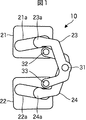
図1は従来の隠しヒンジ10の例を示す図である。同図に示されるように、この隠しヒンジ10は、取り付け板21、および取り付け板22を有する構成とされている。取り付け板21および取り付け板22は、例えば、それぞれ装置の第1の筐体と第2の筐体に取り付けられる。
FIG. 1 is a view showing an example of a conventional
ここで、第1の筐体は、例えば、折り畳んで持ち運ぶことができるノート型パーソナルコンピュータのディスプレイとして構成され、第2の筐体は、例えば、ノート型パーソナルコンピュータの本体として構成される。 Here, the first casing is configured as a display of a notebook personal computer that can be folded and carried, for example, and the second casing is configured as a main body of the notebook personal computer, for example.
また、隠しヒンジ10は、アーム23とアーム24を有する構成とされており、アーム23とアーム24は、ピン31により結合されている。すなわち、ピン31の中心を通る図中奥行方向の線が、例えば、ノート型パーソナルコンピュータのディスプレイ(または本体)回転中心軸線となる。
The
アーム23の端部23aは、取り付け板21の穴21aに係合した状態で穴21aの内部を図中水平(やや斜め)方向にスライドするようになされている。同様に、アーム24の端部24aは、取り付け板22の穴22aに係合した状態で穴22aの内部を図中水平(やや斜め)方向にスライドするようになされている。
The
そして、アーム23の別の端部は、ピン33により取り付け板22に結合されている。同様に、アーム24の別の端部は、ピン32により取り付け板21に結合されている。
The other end of the
なお、隠しヒンジ10においてピンにより結合された各部は、そのピンを軸として回転できるように構成されている。
In addition, each part couple | bonded with the pin in the
また、隠しヒンジ10がノート型パーソナルコンピュータに取り付けられるものである場合、図1に示される状態において、そのノート型パーソナルコンピュータは、折り畳まれた状態(閉じられた状態)となる。
When the hidden
図2は、図1の隠しヒンジ10がノート型パーソナルコンピュータに取り付けられるものである場合、そのノート型パーソナルコンピュータが開かれた状態における隠しヒンジ10を示す図である。例えば、ユーザがノート型パーソナルコンピュータのディスプレイを持ち上げた場合、アーム23の端部23aが穴21aの内部をスライドし、アーム24の端部24aが穴22aの内部をスライドすることによって、ピン31の回転中心軸を中心にディスプレイが回転させられることになる。
FIG. 2 is a diagram showing the hidden
なお、アーム23とアーム24のそれぞれは、ノート型パーソナルコンピュータを開閉できるように折れ曲がった形状とされている。
Each of the
このような隠しヒンジ10を取り付けることにより、ノート型パーソナルコンピュータのディスプレイを開いた状態で、ユーザから隠しヒンジ10が見えないようにすることができる。
By attaching such a
上述したように、図1に示されるような従来の隠しヒンジは、スライド機構を用いている。スライド機構を有する隠しヒンジの場合、例えば、取り付け板21、または、取り付け板22においてヒンジのアームの端部23aまたは端部24aをスライドさせる穴21aまたは穴22aの部分の強度を確保する必要があるために小型化することが難しい。
As described above, the conventional hidden hinge as shown in FIG. 1 uses a slide mechanism. In the case of a hidden hinge having a slide mechanism, for example, it is necessary to secure the strength of the
例えば、図1の取り付け板21の図中垂直方向の長さをこれ以上短くすると、アーム23の端部23aが穴21aに係合した状態で内部を図中水平(やや斜め)方向にスライドするとき、取り付け板21が損壊してしまうおそれがある。
For example, when the length of the mounting
取り付け板21は、例えば、ノート型パーソナルコンピュータのディスプレイに取り付けられる。従って、ノート型パーソナルコンピュータのディスプレイの厚みを取り付け板21の図中垂直方向の長さより薄くすることができない。
The
また、スライド機構は、取り付け板の穴とアームの端部が係合した状態で摺動するようになされているため、摩擦などのよる劣化が懸念され、十分な耐久性を有するように設計する必要がある。しかし、耐久性を確保するためには、使用できる材料などが限られてしまう。 In addition, the slide mechanism is designed to slide with the mounting plate hole and the end of the arm engaged with each other. There is a need. However, in order to ensure durability, materials that can be used are limited.
このように、従来の隠しヒンジは、装置の薄型化や軽量化の妨げとなることがあった。 As described above, the conventional hidden hinge sometimes hinders reduction in thickness and weight of the apparatus.
そこで、本発明では、従来の隠しヒンジとは異なる隠しヒンジを提供することができるようにする。すなわち、高い耐久性を維持しつつ、装置の薄型化や軽量化を可能とするような隠しヒンジを提供できるようにする。 Therefore, in the present invention, a hidden hinge different from the conventional hidden hinge can be provided. That is, it is possible to provide a hidden hinge that can reduce the thickness and weight of the apparatus while maintaining high durability.
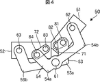
図3は、本発明の一実施の形態に係る隠しヒンジ50の例を示す図である。同図に示されるように、この隠しヒンジ50は、取り付け板51、および取り付け板52を有する構成とされている。取り付け板51および取り付け板52は、例えば、それぞれ装置の第1の筐体と第2の筐体に取り付けられる。
FIG. 3 is a diagram illustrating an example of the hidden
なお、取り付け板51および取り付け板52は設けられないようにし、後述するアーム53、アーム54、リンク71、およびリンク72が直接、第1の筐体または第2の筐体に取り付けられるようにしてもよい。
The mounting
ここで、第1の筐体は、例えば、折り畳んで持ち運ぶことができるノート型パーソナルコンピュータのディスプレイとして構成され、第2の筐体は、例えば、ノート型パーソナルコンピュータの本体として構成される。 Here, the first casing is configured as a display of a notebook personal computer that can be folded and carried, for example, and the second casing is configured as a main body of the notebook personal computer, for example.
また、隠しヒンジ50は、アーム53とアーム54を有する構成とされており、アーム53とアーム54は、ピン61により結合されている。すなわち、ピン61の中心を通る図中奥行方向の線が、例えば、ノート型パーソナルコンピュータのディスプレイ(または本体)回転中心軸線となる。
The hidden
なお、アーム53とアーム54のそれぞれは、ノート型パーソナルコンピュータを開閉できるように折れ曲がった形状とされている。この例では、アーム53は、角部53aと角部53bにおいて折れ曲がった形状とされており、アーム53は、角部54aと角部54bにおいて折れ曲がった形状とされている。
Each of the
さらに、隠しヒンジ50は、リンク71およびリンク72を有する構成とされている。リンク71およびリンク72は、アーム53およびアーム54とは異なり、直線状の形状とされている。
Furthermore, the hidden
アーム53の一方の端部は、ピン63により取り付け板52に結合されている。アーム53の他方の端部は、ピン81によりリンク71に結合されている。アーム54の一方の端部は、ピン62により取り付け板51に結合されている。アーム54の他方の端部は、ピン84によりリンク72に結合されている。
One end of the
リンク71の一方の端部は、ピン81によりアーム53に結合されている。リンク71の他方の端部は、ピン82により取り付け板51に結合されている。リンク72の一方の端部は、ピン84によりアーム54に結合されている。リンク72の他方の端部は、ピン83により取り付け板52に結合されている。
One end of the
なお、隠しヒンジ50においてピンにより結合された各部は、そのピンを軸として回転できるように構成されている。
In addition, each part couple | bonded with the pin in the hidden
なお、隠しヒンジ50がノート型パーソナルコンピュータに取り付けられるものである場合、図3に示される状態において、そのノート型パーソナルコンピュータは、折り畳まれた状態(閉じられた状態)となる。
When the hidden
図4は、図3の隠しヒンジ50がノート型パーソナルコンピュータに取り付けられるものである場合、そのノート型パーソナルコンピュータが開かれた状態における隠しヒンジ50を示す図である。例えば、ユーザがパーソナルコンピュータのディスプレイを持ち上げた場合、リンク71がピン82を軸として回転し、リンク72がピン83を軸として回転することによって、ピン61の回転中心軸を中心にディスプレイが回転させられることになる。
FIG. 4 is a diagram showing the hidden
なお、図3と図4の例においては、隠しヒンジ50において、リンク71は、リンク72より短く構成されている。例えば、隠しヒンジ50がノート型パーソナルコンピュータに取り付けられるものである場合、リンク71がリンク72と同等以上の長さを有していると、ユーザがディスプレイを持ち上げたとき、ディスプレイの下側の端部が本体とぶつかって動かなくなるおそれがあるからである。
3 and 4, the
すなわち、仮にリンク71がより長く構成されている場合、リンク71がピン82を軸として回転する際に、取り付け板51が取り付け板52に対してほぼ直角の向きとなるときに、取り付け板51は、図中下方向に大きく移動することになる。そうすると、取り付け板51に取り付けられたディスプレイの下側の端部が本体とぶつかって動かなくなると考えられる。
In other words, if the
このため、隠しヒンジ50をパーソナルコンピュータなどに取り付ける場合、リンク71は、リンク72より短く構成することが望ましい。勿論、隠しヒンジ50をパーソナルコンピュータなどとは異なる装置に取り付ける場合などは、リンク71をより長く構成するようにしても構わない。
For this reason, when the hidden
また、図3に示される隠しヒンジ50の場合、図1に示される隠しヒンジ10と比較して、アームが必要とする図中垂直方向の長さを短くすることが可能となる。
Further, in the case of the hidden
例えば、図1の隠しヒンジ10の場合、アームが必要とする図中垂直方向の長さは、アーム23の端部23aからアーム24の端部24aまでの長さとなる。これに対して、図3の隠しヒンジ50の場合、アームが必要とする図中垂直方向の長さは、アーム54の角部54bからアーム53の角部53bまでとなる。
For example, in the case of the hidden
すなわち、図3の隠しヒンジ50の場合、ピン62の取り付け位置とピン82の取り付け位置を結んだ線が取り付け板51のほぼ中央の水平な線となるように構成されている。また、ピン63の取り付け位置とピン83の取り付け位置を結んだ線が取り付け板51のほぼ中央の水平な線となるように構成されている。このため、アームが必要とする図中垂直方向の長さを短くすることができるのである。
That is, in the case of the hidden
これにより、本発明の隠しヒンジ50がノート型パーソナルコンピュータの第1の筐体および第2の筐体をより薄く構成することが可能となるのである。
As a result, the hidden
さらに、図3の隠しヒンジ50の場合、図1の隠しヒンジ10の場合と異なり、スライド機構が設けられていない。上述したように、スライド機構は、取り付け板の穴とアームの端部が係合した状態で摺動するようになされているため、摩擦などのよる劣化が懸念され、十分な耐久性を有するように設計する必要がある。
Further, in the case of the hidden
本発明の隠しヒンジ50を用いれば、ノート型パーソナルコンピュータの第1の筐体および第2の筐体をより薄く構成しても、十分な耐久性を有するようにすることができるのである。
If the hidden
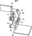
図5は、図4の隠しヒンジ50を別の角度から見た図である。同図に示されるように、隠しヒンジ50は、十分な開閉範囲を有している。なお、隠しヒンジ50単体での開閉範囲は、およそ0°から180°となる。
FIG. 5 is a view of the hidden
図6は、図3の隠しヒンジ50をノート型パーソナルコンピュータに取り付けた場合の例を示す図である。同図の筐体91は、例えば、ノート型パーソナルコンピュータのディスプレイとされ、筐体92は、例えば、ノート型パーソナルコンピュータの本体とされる。図6は、ノート型パーソナルコンピュータが閉じられた状態として記載されており、便宜上、筐体91または筐体92の内部が透視できるように表現されている。
FIG. 6 is a diagram illustrating an example in which the hidden
この例では、筐体91の図中右側端部が斜めの面を有する構成とされており、ノート型パーソナルコンピュータが閉じられた状態で、隠しヒンジ50の一部が筐体92の上側に露出している。
In this example, the right end portion of the
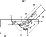
図7は、図6に示されるノート型パーソナルコンピュータが開かれた状態の例を示す図である。同図に示されるノート型パーソナルコンピュータは、例えば、ユーザが筐体91(ディスプレイ)を持ち上げ、リンク71がピン82を軸として回転し、リンク72がピン83を軸として回転することによって、ピン61の回転中心軸を中心にディスプレイが回転させられている。
FIG. 7 is a diagram illustrating an example of a state in which the notebook personal computer illustrated in FIG. 6 is opened. In the notebook type personal computer shown in the figure, for example, the user lifts the casing 91 (display), the
同図に示されるように、隠しヒンジ50は、筐体92、または、筐体91の内部に挿入されて外部から見えないようになされている。ただし、この図では、便宜上、筐体91または筐体92の内部が透視できるように表現されている。
As shown in the figure, the hidden
図8は、図7に示されるノート型パーソナルコンピュータ90を別の角度から見た図である。
FIG. 8 is a view of the notebook
同図に示されるように、開かれた状態のノート型パーソナルコンピュータ90において、筐体91のディスプレイの画面91aが見える状態とされており、筐体92のキーボード92aが打鍵可能な状態とされている。この状態において、筐体91と筐体92の接続部分となる領域95に、ヒンジが見えないようになされている。
As shown in the figure, in the opened notebook
このように、隠しヒンジ50を用いることによって、例えば、ノート型パーソナルコンピュータ90の美的外観をより洗練されたものとすることができる。
Thus, by using the hidden
以上においては、隠しヒンジ50のアーム、リンクなどを取り付けるにあたり、回動可能に取り付けるためにピンを用いて結合するものとして説明したが、アーム、リンクなどを回動可能とすることができれば、必ずしもピンを用いる必要はない。例えば、隠しヒンジ50において、ピン61、ピン62、ピン63、ピン81、ピン82、ピン83、ピン84を設けずに、アーム53とアーム54の端部、および、リンク71とリンク72の端部を回動可能な係合部として構成するようにしてもよい。
In the above description, when attaching the arm, link, etc. of the hidden
また、上述した例では、隠しヒンジ50のアーム53とアーム54は、ピン61により結合されているものと説明したが、必ずしもアーム53とアーム54が結合されている必要はない。すなわち、ピン61に対応する位置において、ノート型パーソナルコンピュータのディスプレイ(または本体)回転中心軸線となるように、隠しヒンジ50を構成することができれば、アーム53とアーム54とが結合される必要はない。
In the above-described example, it has been described that the
図9は、図3の隠しヒンジ50をノート型パーソナルコンピュータに取り付けた場合の別の例を示す図である。同図の筐体101は、例えば、ノート型パーソナルコンピュータのディスプレイとされ、筐体102は、例えば、ノート型パーソナルコンピュータの本体とされる。図9は、ノート型パーソナルコンピュータが閉じられた状態として記載されており、便宜上、筐体101または筐体102の内部が透視できるように表現されている。
FIG. 9 is a diagram showing another example when the hidden
図9の例の場合、図6の場合と異なり、筐体102の図中右側端部が斜めの面を有する構成とされており、ノート型パーソナルコンピュータを開いたときに、ディスプレイの下側の端部が本体のさらに下側に突出するようになされている。また、ノート型パーソナルコンピュータが閉じられた状態で、隠しヒンジ50の一部が筐体101の下側に露出している。このように、隠しヒンジ50の一部が筐体101の下側に露出している場合、ノート型パーソナルコンピュータが閉じられた状態で隠しヒンジ50が視認される可能性は低いといえる。
In the example of FIG. 9, unlike the case of FIG. 6, the right end of the
さらに、図9の例の場合、隠しヒンジ50の取り付け板51および取り付け板52の上下の位置関係が図6の場合と逆となるようにとりつけられており、同様に、アームとリンクも上下の位置関係が図6の場合と逆となるようにとりつけられている。
Furthermore, in the case of the example of FIG. 9, the vertical positional relationship between the mounting
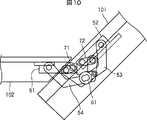
図10は、図9に示されるノート型パーソナルコンピュータが開かれた状態の例を示す図である。同図に示されるノート型パーソナルコンピュータは、例えば、ユーザが筐体101(ディスプレイ)を持ち上げ、リンク71がピン82を軸として回転し、リンク72がピン83を軸として回転することによって、ピン61の回転中心軸を中心にディスプレイが回転させられている。
FIG. 10 is a diagram showing an example of a state in which the notebook personal computer shown in FIG. 9 is opened. In the notebook type personal computer shown in the figure, for example, the user lifts the housing 101 (display), the
同図に示されるように、隠しヒンジ50は、筐体102、または、筐体101の内部に挿入されて外部から見えないようになされている。ただし、この図では、便宜上、筐体101または筐体102の内部が透視できるように表現されている。
As shown in the figure, the hidden
また、図10において、上述したように、ディスプレイ(筐体101)の下側の端部が本体(筐体101)のさらに下側に突出している。 In addition, in FIG. 10, as described above, the lower end of the display (housing 101) protrudes further below the main body (housing 101).
図11は、図10に示されるノート型パーソナルコンピュータ100を別の角度から見た図である。
FIG. 11 is a view of the notebook
同図に示されるように、開かれた状態のノート型パーソナルコンピュータ100において、筐体101のディスプレイの画面101aが見える状態とされており、筐体102のキーボード102aが打鍵可能な状態とされている。この状態において、筐体101と筐体102の接続部分となる領域105に、ヒンジが見えないようになされている。
As shown in the figure, in the opened notebook
さらに、図11の例の場合、図8の場合と異なり、ディスプレイ(筐体101)の下側の端部が本体(筐体102)のさらに下側に突出したことにより、キーボード102aの打鍵面がユーザに向かってやや斜めになるようになされている。このようにすることで、ユーザは、より打鍵しやすくなる。 Further, in the case of the example of FIG. 11, unlike the case of FIG. 8, the lower end of the display (housing 101) protrudes further down on the main body (housing 102). Is slightly inclined toward the user. By doing in this way, it becomes easier for the user to press the key.
このように、隠しヒンジ50を用いることによって、例えば、ノート型パーソナルコンピュータの美的外観をさらに洗練されたものとし、かつ、機能性に富んだものとすることができる。
In this way, by using the hidden
なお、図6または図9において、隠しヒンジ50の一部が露出している部分には、例えば、蛇腹のような収縮するカバーを設けて露出している部分を覆うようにすれば、ノート型パーソナルコンピュータ100の美的外観はさらに洗練されたものとなる。
In FIG. 6 or FIG. 9, for example, if the portion where the hidden
以上においては、隠しヒンジ50をパーソナルコンピュータに用いる例について説明したが、他の装置に用いられるようにしてもよい。すなわち、本発明によれば、可動部分を有する装置の美的外観をより洗練されたものとすることができ、かつ、耐久性を高めることができる。
In the above, an example in which the hidden
また、本発明の実施の形態は、上述した実施の形態に限定されるものではなく、本発明の要旨を逸脱しない範囲において種々の変更が可能である。 The embodiments of the present invention are not limited to the above-described embodiments, and various modifications can be made without departing from the scope of the present invention.
50 隠しヒンジ, 51 取り付け板, 52 取り付け板, 53 アーム, 54 アーム, 61 ピン, 62 ピン , 63 ピン, 71 リンク, 72 リンク, 81 ピン, 82 ピン, 83 ピン, 84 ピン, 90 ノート型パーソナルコンピュータ, 91 第1の筐体 92 第2の筐体, 100 ノート型パーソナルコンピュータ, 101 第1の筐体, 102 第2の筐体
50 Hidden Hinge, 51 Mounting Plate, 52 Mounting Plate, 53 Arm, 54 Arm, 61 Pin, 62 Pin, 63 Pin, 71 Link, 72 Link, 81 Pin, 82 Pin, 83 Pin, 84 Pin, 90 Notebook Personal Computer , 91
Claims (6)
一方の端部において前記第1の筐体に対して回動可能に取り付けられた第1のリンクと、
一方の端部がピンによって前記第2の筐体に取り付けられた第2のリンクと、
一方の端部において前記第2の筐体に対して回動可能に取り付けられ、他方の端部において前記第1のリンクに対して回動可能に取り付けられた第1のアームと、
一方の端部において前記第1の筐体に対して回動可能に取り付けられ、他方の端部が前記第2のリンクに対して回動可能に取り付けられた前記第2のアームとを有するヒンジを備える
電子機器。 A first housing and a second housing that rotate about a rotation axis;
A first link rotatably attached to the first housing at one end;
A second link having one end attached to the second housing by a pin;
A first arm pivotally attached to the second housing at one end and pivotally attached to the first link at the other end;
A hinge having one end portion rotatably attached to the first casing and the other end rotatably attached to the second link. An electronic device comprising:
前記第1の筐体または前記第2の筐体が回転させられた場合、前記ヒンジが前記第1の筐体または前記第2の筐体の内部に挿入される
請求項1に記載の電子機器。 The first casing or the second casing is rotated by the hinge according to the use mode of the electronic device,
The electronic device according to claim 1, wherein when the first casing or the second casing is rotated, the hinge is inserted into the first casing or the second casing. .
前記第1のリンクの直線状の長さと前記第2のリンクの直線状の長さが異なる
請求項2に記載の電子機器。 In the hinge,
The electronic device according to claim 2, wherein the linear length of the first link is different from the linear length of the second link.
前記第1のアームおよび前記第2のアームは、折れ曲がった形状とされ、
前記第1のリンクおよび前記第2のリンクは、直線状の形状とされる
請求項3に記載の電子機器。 In the hinge,
The first arm and the second arm have a bent shape,
The electronic device according to claim 3, wherein the first link and the second link have a linear shape.
前記第2の筐体は、キーボードを有する筐体とされ、
前記第1の筐体と前記第2の筐体からなるノート型パーソナルコンピュータとして構成される
請求項4に記載の電子機器。 The first casing is a casing having a display;
The second casing is a casing having a keyboard,
The electronic device according to claim 4, wherein the electronic device is configured as a laptop personal computer including the first casing and the second casing.
一方の端部がピンによって第2の筐体に取り付けられた第2のリンクと、
一方の端部において前記第2の筐体に対して回動可能に取り付けられ、他方の端部において前記第1のリンクに対して回動可能に取り付けられた第1のアームと、
一方の端部において前記第1の筐体に対して回動可能に取り付けられ、他方の端部が前記第2のリンクに対して回動可能に取り付けられた前記第2のアームとを有する
ヒンジ。 A first link pivotally attached to the first housing at one end;
A second link with one end attached to the second housing by a pin;
A first arm pivotally attached to the second housing at one end and pivotally attached to the first link at the other end;
A hinge having a second arm rotatably attached to the first housing at one end and a second arm rotatably attached to the second link; .
Priority Applications (3)
| Application Number | Priority Date | Filing Date | Title |
|---|---|---|---|
| JP2011000954A JP2012141915A (en) | 2011-01-06 | 2011-01-06 | Electronic apparatus and hinge |
| US13/339,515 US8599546B2 (en) | 2011-01-06 | 2011-12-29 | Electronic apparatus and hinge |
| CN2011104534254A CN102606616A (en) | 2011-01-06 | 2011-12-30 | Electronic Apparatus And Hinge |
Applications Claiming Priority (1)
| Application Number | Priority Date | Filing Date | Title |
|---|---|---|---|
| JP2011000954A JP2012141915A (en) | 2011-01-06 | 2011-01-06 | Electronic apparatus and hinge |
Publications (2)
| Publication Number | Publication Date |
|---|---|
| JP2012141915A true JP2012141915A (en) | 2012-07-26 |
| JP2012141915A5 JP2012141915A5 (en) | 2014-01-23 |
Family
ID=46455068
Family Applications (1)
| Application Number | Title | Priority Date | Filing Date |
|---|---|---|---|
| JP2011000954A Pending JP2012141915A (en) | 2011-01-06 | 2011-01-06 | Electronic apparatus and hinge |
Country Status (3)
| Country | Link |
|---|---|
| US (1) | US8599546B2 (en) |
| JP (1) | JP2012141915A (en) |
| CN (1) | CN102606616A (en) |
Cited By (6)
| Publication number | Priority date | Publication date | Assignee | Title |
|---|---|---|---|---|
| JP2018113050A (en) * | 2018-02-27 | 2018-07-19 | レノボ・シンガポール・プライベート・リミテッド | Portable information device |
| US10185355B2 (en) | 2017-01-10 | 2019-01-22 | Lenovo (Singapore) Pte. Ltd. | Portable information device |
| TWI687792B (en) * | 2017-04-13 | 2020-03-11 | 仁寶電腦工業股份有限公司 | Electronic device |
| US10705575B2 (en) | 2017-08-30 | 2020-07-07 | Sharp Kabushiki Kaisha | Hinge device and electronic device |
| KR102492937B1 (en) * | 2022-02-06 | 2023-01-30 | 주식회사 아이피엘랩스 | Hinge apparatus for foldable device |
| KR102560376B1 (en) * | 2022-01-28 | 2023-07-27 | 주식회사 아이피엘랩스 | Hinge apparatus for foldable device |
Families Citing this family (12)
| Publication number | Priority date | Publication date | Assignee | Title |
|---|---|---|---|---|
| US8971031B2 (en) * | 2012-08-07 | 2015-03-03 | Creator Technology B.V. | Display system with a flexible display |
| CN103792993B (en) * | 2012-10-29 | 2017-02-08 | 英业达科技有限公司 | Electronic device with concealed rotation shaft structure |
| CN106462181B (en) * | 2014-04-29 | 2019-10-25 | 惠普发展公司,有限责任合伙企业 | Hinge assembly for computing device |
| US9823693B2 (en) | 2014-08-26 | 2017-11-21 | Andrew Flessas | Robotically controlled convertible display |
| US9477269B2 (en) * | 2014-09-23 | 2016-10-25 | Dell Products, Lp | Book-style sliding pivot hinge |
| WO2017086996A1 (en) | 2015-11-20 | 2017-05-26 | Hewlett-Packard Development Company, L.P. | Hinge mechanism for a computing device |
| CN206413045U (en) * | 2016-12-28 | 2017-08-15 | 杭州安费诺飞凤通信部品有限公司 | A kind of deformable hinge and mobile terminal of the application of rotation of mobile terminal component |
| US10465427B2 (en) | 2017-02-08 | 2019-11-05 | Compal Electronics, Inc. | Electronic device and hinge assembly thereof |
| TWI674603B (en) | 2017-02-08 | 2019-10-11 | 仁寶電腦工業股份有限公司 | Electronic device and hinge assembly thereof |
| US10761571B1 (en) * | 2018-09-27 | 2020-09-01 | Apple Inc. | Linkage assembly for a portable electronic device |
| JP6719608B1 (en) * | 2019-02-18 | 2020-07-08 | レノボ・シンガポール・プライベート・リミテッド | Electronics |
| TWI746217B (en) * | 2020-10-20 | 2021-11-11 | 宏碁股份有限公司 | Hinge structure for flexible display and portable electronic device |
Citations (4)
| Publication number | Priority date | Publication date | Assignee | Title |
|---|---|---|---|---|
| JPH0362978U (en) * | 1989-10-20 | 1991-06-19 | ||
| JP3022762U (en) * | 1995-09-19 | 1996-04-02 | 中東産業株式会社 | Hinge |
| JP2001085862A (en) * | 1999-09-17 | 2001-03-30 | Casio Comput Co Ltd | Electronic device |
| US20060282983A1 (en) * | 2005-06-21 | 2006-12-21 | Daniele Zetti | Sprung hinge for supporting a closure element |
Family Cites Families (6)
| Publication number | Priority date | Publication date | Assignee | Title |
|---|---|---|---|---|
| JP4481901B2 (en) | 2005-08-08 | 2010-06-16 | 日東工器株式会社 | Hidden hinge with automatic closing function |
| JP5118387B2 (en) | 2007-05-18 | 2013-01-16 | 株式会社ニシムラ | Hidden hinge with four links |
| CN201202339Y (en) * | 2008-06-11 | 2009-03-04 | 霍泰安 | Inner concealed hinge |
| US8792947B2 (en) * | 2010-08-20 | 2014-07-29 | Blackberry Limited | Mobile device |
| JP5039216B2 (en) * | 2011-02-24 | 2012-10-03 | 株式会社東芝 | Electronics |
| JP5175964B1 (en) * | 2011-09-27 | 2013-04-03 | 株式会社東芝 | Electronics |
-
2011
- 2011-01-06 JP JP2011000954A patent/JP2012141915A/en active Pending
- 2011-12-29 US US13/339,515 patent/US8599546B2/en not_active Expired - Fee Related
- 2011-12-30 CN CN2011104534254A patent/CN102606616A/en active Pending
Patent Citations (4)
| Publication number | Priority date | Publication date | Assignee | Title |
|---|---|---|---|---|
| JPH0362978U (en) * | 1989-10-20 | 1991-06-19 | ||
| JP3022762U (en) * | 1995-09-19 | 1996-04-02 | 中東産業株式会社 | Hinge |
| JP2001085862A (en) * | 1999-09-17 | 2001-03-30 | Casio Comput Co Ltd | Electronic device |
| US20060282983A1 (en) * | 2005-06-21 | 2006-12-21 | Daniele Zetti | Sprung hinge for supporting a closure element |
Cited By (6)
| Publication number | Priority date | Publication date | Assignee | Title |
|---|---|---|---|---|
| US10185355B2 (en) | 2017-01-10 | 2019-01-22 | Lenovo (Singapore) Pte. Ltd. | Portable information device |
| TWI687792B (en) * | 2017-04-13 | 2020-03-11 | 仁寶電腦工業股份有限公司 | Electronic device |
| US10705575B2 (en) | 2017-08-30 | 2020-07-07 | Sharp Kabushiki Kaisha | Hinge device and electronic device |
| JP2018113050A (en) * | 2018-02-27 | 2018-07-19 | レノボ・シンガポール・プライベート・リミテッド | Portable information device |
| KR102560376B1 (en) * | 2022-01-28 | 2023-07-27 | 주식회사 아이피엘랩스 | Hinge apparatus for foldable device |
| KR102492937B1 (en) * | 2022-02-06 | 2023-01-30 | 주식회사 아이피엘랩스 | Hinge apparatus for foldable device |
Also Published As
| Publication number | Publication date |
|---|---|
| CN102606616A (en) | 2012-07-25 |
| US8599546B2 (en) | 2013-12-03 |
| US20120176740A1 (en) | 2012-07-12 |
Similar Documents
| Publication | Publication Date | Title |
|---|---|---|
| JP2012141915A (en) | Electronic apparatus and hinge | |
| CN109871067B (en) | Rotating shaft module and electronic device | |
| CN109710027B (en) | Portable electronic device | |
| JP5599226B2 (en) | Switchgear | |
| TWI669593B (en) | Adjustable display housing assembly | |
| WO2012032815A1 (en) | Opening/closing device | |
| US20170139447A1 (en) | Hinge assembly | |
| US10168746B2 (en) | Hinge mechanism for a computing device | |
| JP4693069B2 (en) | Sliding / rotating mounting unit and mobile phone using the same | |
| JP5944095B2 (en) | Switchgear | |
| JP2017134758A (en) | Information processor | |
| US20110047751A1 (en) | Hinge and an electronic device with the same | |
| JP6310694B2 (en) | Biaxial hinge device | |
| TW201925963A (en) | Hinge module and electronic device using the same | |
| TWM539210U (en) | Electronic device | |
| TW201116728A (en) | Electronic device | |
| JP6524853B2 (en) | Folding type information processor | |
| EP3137963B1 (en) | Hinge assembly for a computing device | |
| TW201033489A (en) | Hinge structure | |
| JP2009052581A (en) | Hinge unit and collapsible electronic equipment | |
| JP5348690B2 (en) | Slide rotation hinge and portable device | |
| JP4633849B1 (en) | Portable electronic devices | |
| TW201617757A (en) | Computing device with a rotatable display member | |
| JP5387816B2 (en) | Rotating casing connecting device and method, and portable device using the same | |
| TWI384139B (en) | Sliding device |
Legal Events
| Date | Code | Title | Description |
|---|---|---|---|
| A521 | Request for written amendment filed |
Free format text: JAPANESE INTERMEDIATE CODE: A523 Effective date: 20131203 |
|
| A621 | Written request for application examination |
Free format text: JAPANESE INTERMEDIATE CODE: A621 Effective date: 20131203 |
|
| A131 | Notification of reasons for refusal |
Free format text: JAPANESE INTERMEDIATE CODE: A131 Effective date: 20140812 |
|
| A977 | Report on retrieval |
Free format text: JAPANESE INTERMEDIATE CODE: A971007 Effective date: 20140813 |
|
| A521 | Request for written amendment filed |
Free format text: JAPANESE INTERMEDIATE CODE: A523 Effective date: 20140926 |
|
| A131 | Notification of reasons for refusal |
Free format text: JAPANESE INTERMEDIATE CODE: A131 Effective date: 20150226 |
|
| A02 | Decision of refusal |
Free format text: JAPANESE INTERMEDIATE CODE: A02 Effective date: 20150630 |