JP2012247638A - Imaging apparatus - Google Patents
Imaging apparatus Download PDFInfo
- Publication number
- JP2012247638A JP2012247638A JP2011119405A JP2011119405A JP2012247638A JP 2012247638 A JP2012247638 A JP 2012247638A JP 2011119405 A JP2011119405 A JP 2011119405A JP 2011119405 A JP2011119405 A JP 2011119405A JP 2012247638 A JP2012247638 A JP 2012247638A
- Authority
- JP
- Japan
- Prior art keywords
- imaging
- light
- unit
- image sensor
- space
- Prior art date
- Legal status (The legal status is an assumption and is not a legal conclusion. Google has not performed a legal analysis and makes no representation as to the accuracy of the status listed.)
- Granted
Links
- 238000003384 imaging method Methods 0.000 title claims abstract description 90
- 230000000149 penetrating effect Effects 0.000 claims abstract description 7
- 238000000638 solvent extraction Methods 0.000 claims abstract 2
- 230000003287 optical effect Effects 0.000 claims description 40
- 230000005540 biological transmission Effects 0.000 claims description 28
- 238000005192 partition Methods 0.000 claims description 22
- 239000000428 dust Substances 0.000 abstract description 19
- 238000007789 sealing Methods 0.000 abstract description 4
- 230000010355 oscillation Effects 0.000 abstract 5
- 230000007246 mechanism Effects 0.000 description 8
- 229910052751 metal Inorganic materials 0.000 description 7
- 239000002184 metal Substances 0.000 description 7
- 239000000843 powder Substances 0.000 description 7
- 230000000694 effects Effects 0.000 description 5
- 230000035515 penetration Effects 0.000 description 5
- 239000011521 glass Substances 0.000 description 4
- 238000010827 pathological analysis Methods 0.000 description 4
- 239000000758 substrate Substances 0.000 description 4
- 238000001816 cooling Methods 0.000 description 3
- 238000010586 diagram Methods 0.000 description 3
- 238000000034 method Methods 0.000 description 2
- 230000035945 sensitivity Effects 0.000 description 2
- 230000000007 visual effect Effects 0.000 description 2
- VYPSYNLAJGMNEJ-UHFFFAOYSA-N Silicium dioxide Chemical compound O=[Si]=O VYPSYNLAJGMNEJ-UHFFFAOYSA-N 0.000 description 1
- 238000006243 chemical reaction Methods 0.000 description 1
- 230000005494 condensation Effects 0.000 description 1
- 238000009833 condensation Methods 0.000 description 1
- 239000006059 cover glass Substances 0.000 description 1
- 238000003745 diagnosis Methods 0.000 description 1
- 230000017525 heat dissipation Effects 0.000 description 1
- 238000009434 installation Methods 0.000 description 1
- 239000012466 permeate Substances 0.000 description 1
- 230000002265 prevention Effects 0.000 description 1
- 238000009877 rendering Methods 0.000 description 1
- 230000011218 segmentation Effects 0.000 description 1
- 239000000741 silica gel Substances 0.000 description 1
- 229910002027 silica gel Inorganic materials 0.000 description 1
- GGCZERPQGJTIQP-UHFFFAOYSA-N sodium;9,10-dioxoanthracene-2-sulfonic acid Chemical compound [Na+].C1=CC=C2C(=O)C3=CC(S(=O)(=O)O)=CC=C3C(=O)C2=C1 GGCZERPQGJTIQP-UHFFFAOYSA-N 0.000 description 1
Images


Classifications
-
- G—PHYSICS
- G02—OPTICS
- G02B—OPTICAL ELEMENTS, SYSTEMS OR APPARATUS
- G02B21/00—Microscopes
- G02B21/24—Base structure
-
- G—PHYSICS
- G02—OPTICS
- G02B—OPTICAL ELEMENTS, SYSTEMS OR APPARATUS
- G02B21/00—Microscopes
- G02B21/36—Microscopes arranged for photographic purposes or projection purposes or digital imaging or video purposes including associated control and data processing arrangements
-
- G—PHYSICS
- G02—OPTICS
- G02B—OPTICAL ELEMENTS, SYSTEMS OR APPARATUS
- G02B21/00—Microscopes
- G02B21/16—Microscopes adapted for ultraviolet illumination ; Fluorescence microscopes
-
- G—PHYSICS
- G02—OPTICS
- G02B—OPTICAL ELEMENTS, SYSTEMS OR APPARATUS
- G02B21/00—Microscopes
- G02B21/36—Microscopes arranged for photographic purposes or projection purposes or digital imaging or video purposes including associated control and data processing arrangements
- G02B21/362—Mechanical details, e.g. mountings for the camera or image sensor, housings
Abstract
Description
本発明は、例えば顕微鏡等の光学装置に用いられる撮像装置に関するものである。 The present invention relates to an imaging apparatus used in an optical apparatus such as a microscope.
顕微鏡観察においては、細胞の形態により診断を行う病理診断や、微弱な蛍光により標本の変化を測定するイメージング等を行うにあたり、高画質な画像が要求される。画像を得るための手段としては、撮像媒体として在来からの銀塩フィルムを用いた撮像装置に代えて、CCD等の撮像素子を用いた撮像装置が用いられるようになっている(例えば、特許文献1から3参照)。 In microscopic observation, high-quality images are required for pathological diagnosis in which diagnosis is performed based on cell morphology, imaging for measuring changes in specimens by weak fluorescence, and the like. As a means for obtaining an image, an imaging apparatus using an imaging element such as a CCD is used instead of an imaging apparatus using a conventional silver salt film as an imaging medium (for example, a patent) Reference 1 to 3).
特許文献1に開示されている撮像装置は、被写体を撮像するための固体撮像素子と、固体撮像素子を冷却する固体撮像素子冷却手段と、電気信号配線用のプリント基板とを備え、電気信号配線用のプリント基板が、固体撮像素子及び固体撮像素子冷却手段を密閉する密閉手段の一部を構成している。 An imaging apparatus disclosed in Patent Document 1 includes a solid-state imaging device for imaging a subject, a solid-state imaging device cooling unit that cools the solid-state imaging device, and a printed circuit board for electrical signal wiring. The printed circuit board for use constitutes a part of the sealing means for sealing the solid-state image sensor and the solid-state image sensor cooling means.
特許文献2に開示されている撮像装置は、撮像装置内部が区画壁により、撮像素子が配設された第一の空間と開口を有する第二の空間とに区画されており、第一の空間と第二の空間とが、カメラ本体よりも熱伝導率の高い伝熱部材を介して熱的に接続されている。 The imaging device disclosed in Patent Document 2 is partitioned into a first space in which the imaging device is disposed and a second space having an opening, by a partition wall, inside the imaging device. And the second space are thermally connected via a heat transfer member having a higher thermal conductivity than the camera body.
特許文献3に開示されている撮像装置は、撮像装置内部に撮像素子を複数設けると共に、対物レンズから各撮像素子までの光路を分割して各撮像素子に導く光路分割手段を備えている。また、この撮像装置は、光路分割手段から各撮像素子までの各光路中に互いに焦点距離の異なるレンズを設けて、各撮像素子の受光面上に結ばれる像の倍率を異ならせている。 The imaging apparatus disclosed in Patent Document 3 includes a plurality of imaging elements inside the imaging apparatus, and includes an optical path dividing unit that divides an optical path from the objective lens to each imaging element and guides it to each imaging element. In addition, in this imaging apparatus, lenses having different focal lengths are provided in each optical path from the optical path dividing means to each imaging element, and the magnifications of the images formed on the light receiving surfaces of the imaging elements are made different.
ところで、病理診断などで用いる撮像素子は、色再現が重要視される。また、蛍光や発光といった微弱光を観察したい場合には、感度が重要視される。このように、観察法によって求められる撮像素子の特性は異なる。そこで、撮像装置内部にこれら特性の異なる撮像素子を配置すれば、様々な用途に1つの撮像装置で対応する事が可能となる。 By the way, color reproduction is regarded as important for image sensors used in pathological diagnosis and the like. Sensitivity is important when observing faint light such as fluorescence or light emission. As described above, the characteristics of the image sensor required by the observation method are different. Therefore, if image sensors having different characteristics are arranged inside the image pickup apparatus, it is possible to deal with various uses with one image pickup apparatus.
このような用途で内部に2つの撮像素子を配置した撮像装置は、微弱光を検出するため、撮像する撮像素子にのみ観察光を入射させたい。このため、各撮像素子までの光路を分割する光路分割部を移動させる駆動機構が必要となる。ここで、駆動機構には歯車やガイド機構といった機械要素が用いられるが、これらは使っていくうちに表面が磨耗し、金属粉等のゴミが発生する。 In such an application, an imaging apparatus in which two imaging elements are arranged internally detects weak light, and thus it is desired to make observation light incident only on the imaging element to be imaged. For this reason, a drive mechanism that moves the optical path dividing unit that divides the optical path to each image sensor is required. Here, mechanical elements such as gears and guide mechanisms are used for the drive mechanism, but as these are used, the surface wears and dust such as metal powder is generated.
しかしながら、撮像装置内部には、外部温度変化や撮像素子の冷却によって撮像素子上や撮像素子のカバーガラスに付着する結露を防止するための密閉部や、前述の光路分割部、顕微鏡に接続するための接続部などが設けられている。これらは観察光の経路となるため、前述のゴミが付着すると、被写体の画像に映り込んでしまうという不都合がある。 However, the inside of the image pickup device is connected to a sealed portion for preventing condensation on the image pickup device or the cover glass of the image pickup device due to a change in external temperature or cooling of the image pickup device, the above-mentioned optical path dividing portion, or a microscope. The connection part etc. are provided. Since these are paths of observation light, there is a disadvantage that if the above-mentioned dust adheres, it will be reflected in the image of the subject.
特許文献1に開示されている撮像装置は、撮像装置内部に1つの撮像素子が配置されているだけであり、撮像素子へのゴミの付着を防止する構造とはなっていない。また、特許文献2に開示されている撮像装置は、内部に2つの空間が形成されているが、これは防塵と放熱のための用途であり、撮像装置内部に仮に駆動部を設けた場合に、駆動部からのゴミを撮像させない構成となっていない。また、特許文献3に開示されている撮像装置は、内部の光路分割手段を動かす例が実施例で述べられているが、具体的な方法は開示されていない。 The imaging apparatus disclosed in Patent Document 1 has only one imaging element disposed inside the imaging apparatus, and does not have a structure for preventing dust from adhering to the imaging element. In addition, the imaging device disclosed in Patent Document 2 has two spaces formed therein, which is used for dust prevention and heat dissipation, and when a drive unit is provided inside the imaging device. In this configuration, dust from the drive unit is not imaged. Moreover, although the example which moves an internal optical path division | segmentation means is described by the Example about the imaging device currently disclosed by patent document 3, the specific method is not disclosed.
本発明は、上記事情に鑑みてなされたもので、撮像素子を備える撮像装置において、駆動部から発生するゴミ等が観察光の光路へ侵入してしまうことを防止できる撮像装置を提供することを目的とする。 The present invention has been made in view of the above circumstances, and provides an imaging apparatus capable of preventing dust generated from a drive unit from entering the optical path of observation light in an imaging apparatus including an imaging element. Objective.
上記目的を達成するために、本発明は以下の手段を採用する。
本発明は、筐体と、該筐体の内部を2つの空間に区画する隔壁と、前記筐体内の一方の空間に配置された撮像素子と、前記筐体内の他方の空間に配置された駆動部と、前記隔壁を貫通し、前記駆動部の駆動力を伝達する伝達部と、前記隔壁の前記伝達部の貫通部に設けられ、前記伝達部との隙間をシールするシール部と、前記一方の空間において前記伝達部に接続され、前記伝達部により伝達された駆動力によって移動して、前記撮像素子及び前記撮像素子とは別の部材の少なくとも一つに被写体からの光を導くように切り替えられる導光部とを備える撮像装置を採用する。
In order to achieve the above object, the present invention employs the following means.
The present invention includes a housing, a partition wall that divides the interior of the housing into two spaces, an image sensor disposed in one space in the housing, and a drive disposed in the other space in the housing. A transmission part that penetrates the partition and transmits the driving force of the drive part, a seal part that is provided in the penetration part of the transmission part of the partition and seals the gap between the transmission part, and the one Is switched to be guided to light from the subject to at least one of the image sensor and another member different from the image sensor by being connected to the transmitter and moving by the driving force transmitted by the transmitter. An imaging device including a light guide unit is employed.
本発明に係る撮像装置は、隔壁により筐体の内部が2つの空間に区画され、これら2つの空間のうち、一方の空間に撮像素子が配置されるとともに、他方の空間に駆動部が配置されている。また、駆動部を動作させることで、駆動部の駆動力が、隔壁を貫通する伝達部により前記一方の空間に配置された導光部に伝達される。これにより、導光部は、伝達部により伝達された駆動力によって移動して、撮像素子及び前記撮像素子とは別の部材の少なくとも一つに被写体からの光を導くように切り替えられる。 In the imaging apparatus according to the present invention, the interior of the housing is partitioned into two spaces by a partition wall, and an imaging element is disposed in one of the two spaces, and a drive unit is disposed in the other space. ing. Further, by operating the driving unit, the driving force of the driving unit is transmitted to the light guide unit disposed in the one space by the transmission unit penetrating the partition wall. Thereby, the light guide unit is switched so as to move by the driving force transmitted by the transmission unit and guide light from the subject to at least one of the image sensor and the member different from the image sensor.
この場合において、隔壁の伝達部の貫通部には、貫通部の壁面と伝達部との隙間をシールするシール部が設けられている。これにより、他方の空間に配置された駆動部から発生した金属粉等のゴミが、撮像素子が配置された一方の空間に侵入してしまうことを防止することができ、ゴミなどが映り込まない高品位の観察像を得ることができる。さらに、駆動部と撮像素子とを分離して配置することで、故障頻度が比較的高い駆動部へのアクセスを容易なものとすることができ、メンテナンス性を向上することができる。 In this case, a seal part that seals a gap between the wall surface of the penetration part and the transmission part is provided in the penetration part of the transmission part of the partition wall. As a result, dust such as metal powder generated from the drive unit arranged in the other space can be prevented from entering the one space where the image sensor is arranged, and no dust is reflected. A high-quality observation image can be obtained. Furthermore, by disposing the drive unit and the image sensor separately, it is possible to facilitate access to the drive unit having a relatively high failure frequency, and improve maintainability.
上記発明において、前記部材が、撮像素子であることとしてもよい。
このようにすることで、導光部は、伝達部により伝達された駆動力によって移動して、複数の撮像素子の少なくとも一つに被写体からの光を導くように切り替えられる。
In the above invention, the member may be an image sensor.
By doing in this way, the light guide unit is switched so as to move by the driving force transmitted by the transmission unit and guide light from the subject to at least one of the plurality of imaging elements.
上記発明において、複数の前記撮像素子が、互いに特性の異なることとしてもよい。
このようにすることで、用途に応じて撮像素子を使い分けて被写体の画像を取得することができる。例えば、一方の撮像素子を高感度なものとして、他方の撮像素子を演色性の高いものとすることで、一方の撮像素子により微弱な蛍光等を検出して被写体の画像を取得するとともに、他方の撮像素子により病理診断に好適な色再現性の高い被写体の画像を取得することができる。
In the above invention, the plurality of imaging elements may have different characteristics from each other.
By doing in this way, it is possible to acquire an image of the subject by properly using the image sensor depending on the application. For example, by making one image sensor highly sensitive and making the other image sensor highly color-rendering, one image sensor detects weak fluorescence and the like to acquire an image of the subject, while the other An image of a subject with high color reproducibility suitable for pathological diagnosis can be acquired with this imaging element.
上記発明において、複数の前記撮像素子のいずれかが、前記被写体からの光の光路上に配置され、前記導光部が、前記伝達部により伝達された駆動力によって、前記被写体からの光の光路上に挿脱されることとしてもよい。
このような構成とすることで、駆動部を動作させることにより、駆動力を伝達部により伝達し、導光部を移動させて、複数の撮像素子のいずれかに被写体からの光を導くように切り替えることができる。具体的には、導光部を被写体からの光の光路上から外した場合には、被写体からの光の光路上に配置された撮像素子に光を導くことができる。また、導光部を被写体からの光の光路上に挿入した場合には、他の撮像素子に光を導くことができる。
In the above invention, any one of the plurality of imaging elements is disposed on an optical path of light from the subject, and the light guide unit emits light of the light from the subject by the driving force transmitted by the transmission unit. It may be inserted / removed on the road.
With such a configuration, by operating the drive unit, the driving force is transmitted by the transmission unit, and the light guide unit is moved so that the light from the subject is guided to one of the plurality of imaging elements. Can be switched. Specifically, when the light guide unit is removed from the optical path of light from the subject, the light can be guided to an image sensor disposed on the optical path of light from the subject. In addition, when the light guide unit is inserted on the optical path of light from the subject, light can be guided to another image sensor.
上記発明において、前記駆動部が、モータと、該モータの回転軸に固定されたピニオン部とから構成され、前記伝達部が、前記ピニオン部に嵌合するラック部と、該ラック部と前記導光部とを接続する接続部材とから構成されていることとしてもよい。
このような構成とすることで、モータを回転させることで、モータの回転軸に固定されたピニオン部を回転させ、該ピニオン部に嵌合するラック部を動作させることができる。これにより、該ラック部に接続部材を介して接続された導光部を動作させることができる。
In the above invention, the drive unit includes a motor and a pinion unit fixed to a rotation shaft of the motor, and the transmission unit includes a rack unit fitted into the pinion unit, the rack unit, and the guide. It is good also as being comprised from the connection member which connects an optical part.
With such a configuration, by rotating the motor, the pinion portion fixed to the rotation shaft of the motor can be rotated, and the rack portion fitted to the pinion portion can be operated. Thereby, the light guide part connected to the rack part via the connection member can be operated.
上記発明において、前記撮像素子の周りを覆うように配置され、少なくとも一部が光を透過可能な部材で構成された密閉容器を備えることとしてもよい。
撮像素子を密閉容器に収容することで、駆動部からの金属粉等のゴミが撮像素子に付着することを確実に防止することができ、より高品位の観察像を得ることができる。
In the above-mentioned invention, it is good also as providing the airtight container which is arranged so that the circumference of the above-mentioned image sensor may be covered, and at least one part was constituted by the member which can permeate light.
By accommodating the image sensor in the sealed container, it is possible to reliably prevent dust such as metal powder from the drive unit from adhering to the image sensor, and to obtain a higher quality observation image.
上記発明において、前記導光部がプリズムであることとしてもよい。
このようにすることで、被写体からの光をプリズムにより反射して、所望の撮像素子に導くことができる。
In the above invention, the light guide section may be a prism.
In this way, light from the subject can be reflected by the prism and guided to a desired image sensor.
上記発明において、前記導光部がミラーであることとしてもよい。
このようにすることで、被写体からの光をミラーにより反射して、所望の撮像素子に導くことができる。また、ミラーは比較的軽量であるため、伝達部にかかる荷重を低減することができ、より正確な位置決めが可能となる。
In the above invention, the light guide section may be a mirror.
In this way, light from the subject can be reflected by the mirror and guided to a desired image sensor. Further, since the mirror is relatively light, it is possible to reduce the load applied to the transmission unit and to perform more accurate positioning.
上記発明において、複数の前記撮像素子が、前記隔壁の表面に沿う方向に並んで配置され、前記伝達部が、前記貫通部を回動中心として前記導光部を回動させることとしてもよい。
上記発明において、複数の前記撮像素子が、前記隔壁の表面に沿う方向に並んで配置され、前記伝達部が、前記隔壁の表面に沿う方向に前記導光部を移動させることとしてもよい。
上記発明において、複数の前記撮像素子が、前記隔壁の表面に直交する方向に並んで配置され、前記伝達部が、前記隔壁の表面に直交する方向に前記導光部を移動させることとしてもよい。
In the above invention, the plurality of imaging elements may be arranged side by side in a direction along the surface of the partition wall, and the transmission unit may rotate the light guide unit with the penetrating unit as a rotation center.
In the above invention, the plurality of imaging elements may be arranged side by side in a direction along the surface of the partition wall, and the transmission unit may move the light guide unit in a direction along the surface of the partition wall.
In the above invention, the plurality of imaging elements may be arranged in a direction orthogonal to the surface of the partition wall, and the transmission unit may move the light guide unit in a direction orthogonal to the surface of the partition wall. .
本発明によれば、撮像素子を備える撮像装置において、駆動部から発生するゴミ等が観察光の光路へ侵入してしまうことを防止できるという効果を奏する。 ADVANTAGE OF THE INVENTION According to this invention, in an imaging device provided with an imaging device, there exists an effect that it can prevent that the dust etc. which generate | occur | produce from a drive part penetrate | invade into the optical path of observation light.
[第1の実施形態]
以下、本発明の第1の実施形態に係る撮像装置について図1から図4を参照して説明する。
図1は、本発明の第1の実施形態における撮像装置208が搭載された顕微鏡100を示す概略構成図である。
本実施形態に係る顕微鏡100は、顕微鏡本体201と、ステージ202と、対物レンズ203と、接眼レンズ204と、鏡筒205と、結像レンズ207と、カメラ(撮像装置)208とを備えている。
[First Embodiment]
Hereinafter, an imaging apparatus according to a first embodiment of the present invention will be described with reference to FIGS. 1 to 4.
FIG. 1 is a schematic configuration diagram showing a
The
顕微鏡本体201には、ステージ202に対向して配置され、標本像を拡大するための対物レンズ203が設けられている。また、顕微鏡本体201には、標本(被写体)206を載置するとともに、対物レンズ203の光軸900方向に昇降自在に可動するステージ202が設けられている。このような構成を有することで、ステージ202を昇降させることにより、対物レンズ203に対して、対物レンズ203の光軸900方向に標本206の位置決めがされるようになっている。
The microscope
また、顕微鏡本体201には、標本206の像をカメラ208内の撮像素子301上に結像する結像レンズ207と、目視観察のための接眼レンズ204とを装着した鏡筒205が設けられている。そして、結像レンズ207の後段には、カメラ208が設けられている。
The
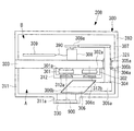
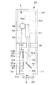
図2は、本実施形態におけるカメラ208の内部構成を示した縦断面図である。
カメラ208は、図2に示すように、有底の円筒状すなわちカップ状の上フタ310および下フタ311から構成される筐体300と、筐体300の内部を2つの空間A、Bに区画する円板状の中板(隔壁)303と、筐体300内の空間(一方の空間)Aに配置された撮像素子301、302と、筐体300内の空間(他方の空間)Bに配置されたモータ(駆動部)308と、中板303を貫通し、モータ308の駆動力を伝達する揺動軸(伝達部)304と、中板303の揺動軸304の貫通部に設けられ、揺動軸304との隙間をシールするベアリング(シール部)305a、305bと、空間Aにおいて揺動軸304に接続されたプリズム(導光部)306とを備えている。
FIG. 2 is a longitudinal sectional view showing the internal configuration of the
As shown in FIG. 2, the
符号301は色再現性に優れたカラー撮像素子、符号302は高感度の白黒撮像素子を示している。各々の撮像素子には、熱交換素子301a、302aが接続されている。熱交換素子301a、302aは、カメラ208の外壁を構成する中板303に隙間なく固定されている。
中板303には、図2の紙面上下方向に開口部が設けられており、揺動軸304を回動させるためのベアリング305a、305bが挿入されている。ベアリング305a、305bは中板303の上下それぞれから組立てる。揺動軸304は、紙面下方向からベアリング305bに挿入して突起部304aを当てつけた後、紙面上方向から揺動軸304に設けられたねじ部にリング321をねじ込むことで、中板303に回転可能に固定されている。ここで、中板303と揺動軸304との隙間は、ベアリング305a、305bによってシールされている。
The
揺動軸304の一端(紙面下方)には、プリズム306の保持部306aが図示されないビスで固定されている。プリズム306と保持部(接続部材)306aとは接着固定されている。
揺動軸304の他端(紙面上方)には、図2および図4に示すように、円弧上の歯車(ラック部)307が図示されないビスで固定されている。歯車307は、モータ308に固定した歯車(ピニオン部)308aと噛み合っており、モータ308の回転力を揺動軸304に伝達する事ができる。モータ308は、基板309にケーブル390により接続されている。モータ308は、例えば、回転量を任意にパルス制御できるステッピングモータ等を用いる。
A holding
As shown in FIGS. 2 and 4, an arcuate gear (rack portion) 307 is fixed to the other end of the swing shaft 304 (above the paper surface) with a screw (not shown). The
中板303と、上フタ310、下フタ311とは、それぞれ図示されないビスで固定されている。下フタ311には、顕微鏡装置接続用の開口311aが設けられている。開口311aの一部は段付形状となっており、防塵ガラス330が接着固定されている。
The
撮像素子301、302は、空間A内に配置された密閉容器312内に収容されている。密閉容器312の下側には2箇所開口が設けられ、これら開口には防塵ガラス312a、312bが隙間なく接着固定されている。密閉容器312と中板303との間には、図示されない弾性部材が配置されていて、密閉容器312内は容易に湿度が進入しない空間が構成されている。密閉容器312内には、例えばシリカゲルといった図示しない除湿手段が設けられている。
The
図4は、図2の空間Bを、紙面上方向から見た平面図である。中板303と上フタ310の外形は、同一もしくは中板303の方が大きい構造となっている。基板309には、PC接続用コネクタ309aが実装されている。上フタ310は、図4において紙面上下方向にコネクタ309aの外形に隙間なく合わせた図示しない開口が設けられている。コネクタ309aは、PCといったカメラに接続した図示しない制御手段に接続されている。このような構成を有することで、モータ308等が配置された空間Bは閉鎖した密閉空間とされている。上フタ310と下フタ311の外形は同一であり、プリズム306等が配置された空間Aも閉鎖した密閉空間とされている。
4 is a plan view of the space B in FIG. 2 as viewed from above in the drawing. The outer shape of the
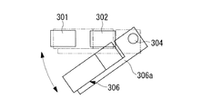
図3は、図2の空間Aを紙面下方向から見た平面図であり、撮像素子301、302とプリズム306、揺動軸304との位置関係を示した図である。図中の矢印は、モータ308の回動で動く揺動軸304の移動方向を示す。図中の2点鎖線は撮像素子302で観察する場合のプリズム306の位置を示しており、実線は撮像素子301で観察する時のプリズム306の位置を示す。
3 is a plan view of the space A in FIG. 2 as viewed from the lower side of the drawing, and shows the positional relationship between the
撮像素子301、302は、中板303の表面に沿う方向に並んで配置されている。
撮像素子301は、対物レンズ203の光軸900上に配置されている。
プリズム306は、標本206からの光(観察光)を光軸900に直交する方向に反射する反射面306bと、反射面306bにより反射された光を光軸900に沿う方向に反射する反射面306cとを備えている。
The
The
The
また、図3に示すように、プリズム306は、揺動軸304により伝達されたモータ308からの駆動力によって、対物レンズ203の光軸900上に挿脱されるようになっている。具体的には、モータ308を動作させることで、中板303の貫通部(ベアリング305a、305b)を回動中心としてプリズム306を回動させ、プリズム306を対物レンズ203の光軸900上に挿脱させるようになっている。
As shown in FIG. 3, the
このようにすることで、モータ308を動作させることにより、モータ308の駆動力を揺動軸304により伝達し、プリズム306を中板303の貫通部回りに回動させて、撮像素子301、302のいずれかに観察光を導くように切り替えることができる。具体的には、プリズム306を光軸900上から外した場合には、光軸900上に配置された撮像素子301に観察光を導くことができる。また、プリズム306を光軸900上に挿入した場合には、撮像素子302に観察光を導くことができる。
Thus, by operating the
上記構成を有する顕微鏡100の作用について以下に説明する。
標本像を取得する場合には、ステージ202上に標本206を載置して、ステージ202を上下動させ、対物レンズ203の焦点位置に標本206を合わせる。これにより、結像レンズ207、接眼レンズ204により標本206の拡大像が観察可能となる。カメラ208で観察する場合には、鏡筒205に設けられた図示されない光路切換機構を用い、カメラ208側に観察光を入射させる。
The operation of the
When acquiring a specimen image, the specimen 206 is placed on the stage 202, the stage 202 is moved up and down, and the specimen 206 is adjusted to the focal position of the
撮像素子301で観察したい場合には、例えばPCといったカメラ208に接続した図示しない制御手段を操作してコネクタ309a、基板309を介してモータ308を回転させる。すると、モータ308の回転力は、歯車308a、歯車307、揺動軸304を介して保持部306aに伝達され、保持部306aを回転してプリズム306を光軸900上から退避させる。これにより、プリズム306は、図3の実線で示した状態となり、観察光を撮像素子301に入射させる。
In order to observe with the
撮像素子302で観察したい場合には、前述と同様に、制御手段を操作してモータ308を前述の場合と反対方向に回転させる。すると、前述の場合と同様に、モータ308の回転力は保持部306aに伝達され、プリズム306は光軸900上に配置される。ここで、プリズム306の微小な位置調整は、モータ308がステッピングモータだった場合はパルス制御で行う。
When it is desired to observe with the
これにより、プリズム306は、図3の二点鎖線で示した状態となる。この場合において、カメラ208に入射した観察光は、図2において、プリズム306によりいったん右側に反射したのち、再度上側に反射されて撮像素子302に入射する。
撮像素子301、302は、熱交換素子301a、302aの駆動により冷却され、熱交換素子で発生した熱は中板303、上フタ310、下フタ311に伝わり外気により冷却される。
As a result, the
The
中板303の上側(空間B)と下側(空間A)とは、揺動軸304とベアリング305a、305bで完全にシールされているため、歯車307、308aで発生する金属粉等のゴミが中板303の下側の空間に落ちて観察光を遮るということがない。またベアリングは一般的にシール形が用いられており、揺動軸304の回転動作でゴミが発生し、観察光を遮るということもない。
Since the upper side (space B) and the lower side (space A) of the
以上のように、本実施形態に係るカメラ208は、中板303により筐体300の内部が2つの空間A、Bに区画され、空間Aに撮像素子301、302が配置されるとともに、空間Bにモータ308が配置されている。また、モータ308を動作させることで、モータ308の駆動力が、中板303を貫通する揺動軸304により空間Aに配置されたプリズム306に伝達される。これにより、プリズム306は、揺動軸304により伝達された駆動力によって移動して、撮像素子301、302のいずれかに観察光を導くように切り替えられる。
As described above, in the
この場合において、中板303の揺動軸304の貫通部には、貫通部の壁面と揺動軸304との隙間をシールするベアリング305a、305bが設けられている。これにより、空間Bに配置されたモータ308からの金属粉等のゴミが、撮像素子301、302が配置された空間Aに侵入してしまうことを防止することができ、ゴミなどが映り込まない高品位の観察像を得ることができる。
In this case,
また、モータ308の駆動力をプリズム306に伝達する伝達機構を、軸や歯車など少ない機械要素で構成しており、無線など実現に高価な電気部品も用いていないため、安価かつ信頼性が高い。さらに、モータ308と撮像素子とを分離して配置することで、故障頻度が比較的高いモータ308へのアクセスを容易なものとすることができ、メンテナンス性を向上することができる。
In addition, the transmission mechanism that transmits the driving force of the
また、撮像素子301、302を、互いに特性の異なるものとすることで、用途に応じて撮像素子を使い分けて標本206の画像を取得することができる。具体的には、本実施形態においては、撮像素子301として色再現性に優れたカラー撮像素子を採用し、撮像素子302として高感度の白黒撮像素子を採用している。このような構成とすることで、撮像素子302により微弱な蛍光等を検出して標本206の画像を取得するとともに、撮像素子301により病理診断に好適な色再現性の高い標本206の画像を取得することができる。
In addition, by making the
また、撮像素子301、302を密閉容器312に収容することで、モータ308等からのゴミが撮像素子301、302に付着することを確実に防止することができ、より高品位の観察像を得ることができる。
Further, by accommodating the
なお、本実施形態では、プリズム306を光軸900上に挿入した場合、観察光を片側の撮像素子302に全て導いていたが、これに限らず、例えば、観察光をプリズム306で分離して撮像素子301と撮像素子302の両方に導くようにしても良い。
また、本実施形態では、上フタ310および下フタ311をカップ状とし、中板303を円板状としたが、空間Aと空間Bとが密閉になるような構成であれば、この形状に限らない。
In this embodiment, when the
In this embodiment, the
[第2の実施形態]
次に、本発明の第2の実施形態に係るカメラ408について、図5から図8を参照して以下に説明する。以下、本実施形態のカメラ408について、第1の実施形態のカメラ208と共通する点については同一の符号を付して説明を省略し、異なる点について主に説明する。
[Second Embodiment]
Next, a
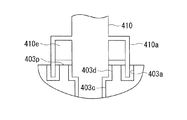
図5は本実施形態におけるカメラ408を示した縦断面図、図6はプリズム306と撮像素子との位置関係を示した空間Aの平面図である。図7は中板403の開口周りの構成を示した上面図であり、図8は中板403の開口周りを部分的に拡大した縦断面図である。
FIG. 5 is a longitudinal sectional view showing the
符号410、411は、ガイド棒を示しており、中板403の上側の空間に配置された、例えばリニアガイドといった図示されないガイド機構に接続されている。ガイド棒410、411は図示されないビスで固定されている。
ガイド棒410の中板403近傍には突起部410aが設けられており、中板403に設けられた溝部403aに0.5mm程度の隙間を持って配置されている。中板403の下側には、ガイド棒410の細い部分とガイド棒411と若干の隙間を持った、断面形状がクランク状の開口403b、403c、403dが設けられている。
A
図7に示すように、突起部410aは、ガイド棒410の駆動範囲によらず中板403に設けられた開口403cを覆うように構成されている。突起部410aは、図7からも明らかな通り、ガイド棒410の短手方向全周を覆う形状となっている。ガイド棒410には突起部410eもあり、中板403の上面403pと隙間を持って配置されている。
As shown in FIG. 7, the protruding
ガイド棒410は、モータ308の回転軸に固定された歯車308aに嵌合するラック409が図示されないビスで固定されており、モータ308の回転力が伝達されるようになっている。具体的には、モータ308を回転駆動させることで、ラック409(およびラック409に固定されたガイド棒410)が、図5における紙面鉛直方向に移動されるようになっている。
ガイド棒411は、保持部306aに図示されないビスで固定されている。
In the
The
上記構成を有するカメラ408の作用について以下に説明する。なお、前述の実施形態に係るカメラ208と同じ作用については説明を省略する。
撮像素子301で観察したい場合には、制御手段を操作して、モータ308の回転力をラック409に伝達し、図5における紙面鉛直方向に保持部306aを移動させる。そして、光軸900上からプリズム306を退避させた状態で標本206の観察を行う。
The operation of the
When it is desired to observe with the
撮像素子302で観察したい場合には、前述の場合と同様に、制御手段を操作してプリズム306を光軸900上に配置する。
歯車308aとラック409との摩擦により発生した金属粉等のゴミは、突起部410a、溝403a、ガイド棒411、開口403bで構成したラビリンス構造により、中板403より紙面下側(空間A)に落ちることが防止される。また、揺動機構と異なり、反射面と平行にプリズム306を動かすため、プリズム306がラフな位置決めであっても観察光の中心ずれが発生しない。
When it is desired to observe with the
The dust such as metal powder generated by the friction between the
以上のように、本実施形態に係るカメラ408によれば、前述の実施形態に係るカメラ208と同様の効果に加えて、プリズム306の位置決めはラフで良いため、より安価に装置を構成する事が可能となる。
As described above, according to the
[第3の実施形態]
次に、本発明の第3の実施形態に係るカメラ508について、図9を参照して以下に説明する。以下、本実施形態のカメラ508について、第1の実施形態のカメラ208と共通する点については同一の符号を付して説明を省略し、異なる点について主に説明する。
[Third embodiment]
Next, a
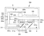
図9は、本実施形態におけるカメラ508を示した縦断面図である。
本実施形態では、プリズム306の代わりに、ミラー(導光部)501、502が設けられている。ミラー501は保持部501aに接着固定され、保持部501aは揺動軸304の一端に図示されないビスで固定されている。ミラー502は、下フタ511の図示されない保持部に接着固定されている。
FIG. 9 is a longitudinal sectional view showing the
In this embodiment, mirrors (light guides) 501 and 502 are provided instead of the
本実施形態では、プリズムをミラーに変えたため、開口511aと撮像素子302との実際の距離(空気換算長は同じ)は第1の実施形態より短くなるため、図2の状態に比べて、撮像素子302は下側に配置されている。また、撮像装置302と密閉容器512との干渉を防止するため、開口512aが設けられている。
In the present embodiment, since the prism is changed to a mirror, the actual distance (the air conversion length is the same) between the
上記構成を有するカメラ508の作用について以下に説明する。なお、前述の実施形態のカメラ208と同じ作用については説明を省略する。
撮像素子301で観察する場合には、モータ308を回転させ、ミラー501を光軸900上から退避させる。すると、開口511aから入射した観察光は、撮像素子301に入射する。
The operation of the
When observing with the
撮像素子302で観察する場合には、モータ308を回転させ、ミラー501を光軸900上に配置する。これにより、開口511aから入射した観察光は、ミラー501、502で偏向され、撮像素子302に入射する。
When observing with the
以上のように、本実施形態に係るカメラ508によれば、前述の実施形態に係るカメラ208と同様の効果に加えて、プリズムより軽いミラーを用いているため、揺動軸304にかかる重力による偏荷重を小さくすることができ、より正確な位置決めが可能となる。
As described above, according to the
[第4の実施形態]
次に、本発明の第4の実施形態に係るカメラ608について、図10を参照して以下に説明する。以下、本実施形態のカメラ608について、第3の実施形態のカメラ508と共通する点については同一の符号を付して説明を省略し、異なる点について主に説明する。
[Fourth Embodiment]
Next, a
図10は、本実施形態におけるカメラ608を示した縦断面図である。
中板603には、図10において左右方向に開口部が設けられており、揺動軸604を回動させるためのベアリング305a、305bが挿入されている。
FIG. 10 is a longitudinal sectional view showing the
The
ベアリング305a、305bは、中板603の左右それぞれから組立てる。揺動軸604を紙面右方向からベアリング305bに挿入し、突起部304aに当てつけた後、揺動軸604に設けられたねじ部に紙面左方向からリング321をねじ込むことで、揺動軸604は中板603に回転可能に固定されている。
The
揺動軸604の一端には、ミラー501の保持部606aが図示されないビスで固定されている。ミラー501と保持部606aとは接着固定されている。
モータ308は、駆動基板609とケーブル391で接続されている。
中板603と上フタ610、下フタ611とは、それぞれ図示されないビスで固定されている。下フタ611には、顕微鏡装置接続用の開口611aが設けられている。開口611aの一部は段付形状となっており、防塵ガラス330が接着固定されている。
A holding
The
The
上記構成を有するカメラ608の作用について以下に説明する。なお、第3の実施形態のカメラ508と同じ作用については説明を省略する。
撮像素子302で観察する場合には、モータ308を回転させ、ミラー501を光軸900上から退避させる。すると、開口611aから入射した観察光は、ミラー502で偏向され、撮像素子302に入射する。
The operation of the
When observing with the
撮像素子301で観察する場合には、モータ308を回転させ、ミラー501を光軸900上に配置する。これにより、開口611aから入射した観察光は、ミラー501で偏向され、撮像素子301に入射する。
When observing with the
以上のように、本実施形態に係るカメラ608によれば、第3の実施形態に係るカメラ508と同様に、プリズムより軽いミラーを用いているため、揺動軸604にかかる重力による偏荷重を小さくすることができ、より正確な位置決めが可能となる。
As described above, according to the
[第5の実施形態]
次に、本発明の第5の実施形態に係るカメラ808について、図11を参照して以下に説明する。以下、本実施形態のカメラについて、第1の実施形態のカメラ208と共通する点については同一の符号を付して説明を省略し、異なる点について主に説明する。
[Fifth Embodiment]
Next, a
図11は、本実施形態におけるカメラ808を示した図である。
中板703には、図11における上下方向に開口部が設けられており、軸704を上下動させるための例えばリニアブッシュのようなベアリング705が挿入、固定されている。
軸704の一端(紙面下方)には、ミラー791が接着固定されている。
FIG. 11 is a diagram showing a
An opening is provided in the
A
軸704の他端(紙面上方)には、ラック707が図示されないビスで固定されている。ラック707は、モータ708に固定した歯車708aと噛み合っており、モータ708の回転力を軸704に伝達するようになっている。モータ708は、基板709とケーブル391で接続されている。モータ708は、例えば、回転量を任意にパルス制御できるステッピングモータ等を用いる。
A
中板703と上フタ710、下フタ711とは、それぞれ図示されないビスで固定されている。下フタ711には、顕微鏡装置接続用の開口711aが設けられている。開口711aの一部は段付形状となっており、防塵ガラス330が接着固定されている。
The
上記構成を有するカメラ808の作用について以下に説明する。なお、第1の実施形態のカメラ208と同じ作用については説明を省略する。
撮像素子302で観察したい場合には、例えばPCといったカメラ808に接続した図示しない制御手段を操作して、モータ708を回転させる。すると、モータ708の回転力は、歯車708a、ラック707、軸704を介してミラー791に伝達され、ミラー791を図11において上側へ移動させる。このときのラック707は図11の二点鎖線で示す位置707aとなり、ミラー791は図11の二点鎖線で示す位置791aとなり、観察光900は、この位置791aのミラー791で偏向され、撮像素子302に入射する。
The operation of the
When observing with the
撮像素子301で観察したい場合には、前述の場合と同様に、制御手段を操作し、モータ708を前述の場合と反対方向に回転させる。すると、前述の場合と同様に、モータ708の回転力は軸704に伝達され、ミラー791は図11の実線で示した位置に配置される。そして、観察光900は、ミラー791で偏向され、撮像素子301に入射する。ミラー791の微小な位置調整は、モータ708がステッピングモータだった場合はパルス制御で行う。
When it is desired to observe with the
中板703の上側(空間B)と下側(空間A)とは、軸704とベアリング705で完全にシールされているため、ラック707と歯車708aとの摩擦により発生する金属粉等のゴミが、中板703の紙面下側の空間Aに落ちて観察光を遮るということがない。また、ベアリング705は、一般的にシール形が用いられており、軸704の上下動作でゴミが発生し、観察光を遮るということもない。
Since the upper side (space B) and the lower side (space A) of the
以上のように、本実施形態に係るカメラ808によれば、前述の実施形態に係るカメラ208と同様の効果に加えて、各構成要素を縦方向に配置することで、カメラのフットプリント(設置面積)を小さくすることができる。
As described above, according to the
以上、本発明の各実施形態について図面を参照して詳述してきたが、具体的な構成はこの実施形態に限られるものではなく、本発明の要旨を逸脱しない範囲の設計変更等も含まれる。例えば、本発明を上記の各実施形態を適宜組み合わせた実施形態に適用してもよい。
また、各実施形態において、2つの撮像素子を備えたカメラを例として説明したが、3つ以上の撮像素子を備えることとしてもよい。
As mentioned above, although each embodiment of the present invention has been described in detail with reference to the drawings, the specific configuration is not limited to this embodiment, and includes design changes and the like without departing from the gist of the present invention. . For example, the present invention may be applied to an embodiment in which the above embodiments are appropriately combined.
Moreover, in each embodiment, although the camera provided with two image sensors was demonstrated as an example, it is good also as providing three or more image sensors.
さらに、各実施形態において、導光部によって、被写体からの光を撮像素子301及びこの撮像素子301とは別の部材である撮像素子302の少なくとも一つに導くように切り替える構成としたが、これに限らず、例えば、上記光を撮像素子301と光電素子(フォトダイオード)との少なくとも一つに導くように切り替える構成や、被写体からの光を撮像素子301と目視観察光路上の光学系との少なくとも一つに導くように切り替える構成としても、同様の効果が得られる。
Further, in each embodiment, the light guide unit is configured to switch the light from the subject to be guided to at least one of the
また、例えば第1の実施形態であれば歯車ではなく、リンク機構を用いても良いし、第2の実施形態であればモータの代わりにソレノイドを使用しても良い。さらに、プリズムを通らない観察光を検出する撮像素子301をより高感度にしてもよい。
For example, in the first embodiment, a link mechanism may be used instead of a gear, and in the second embodiment, a solenoid may be used instead of the motor. Furthermore, the
また、密閉容器312を撮像素子毎に設けても良いし、揺動軸304の中心を支点とするプリズムやミラーの自重によるモーメントを軽減するために、揺動軸304に例えば重りのようなバランサを設けても良い。
また、図4において、上フタ310と下フタ311と中板303が同一外形である例を示したが、機能は各々の空間を分離することなので、上フタ310、下フタ311に対して中板303が大きい外形であっても問題はない。
Further, a sealed
FIG. 4 shows an example in which the
A 空間(一方の空間)
B 空間(他方の空間)
100 顕微鏡
201 顕微鏡本体
202 ステージ
203 対物レンズ
204 接眼レンズ
205 鏡筒
206 標本(被写体)
207 結像レンズ
208 カメラ(撮像装置)
300 筐体
301、302 撮像素子
303 中板(隔壁)
304 揺動軸(伝達部)
305a、305b ベアリング(シール部)
306 プリズム(導光部)
308 モータ(駆動部)
310 上フタ
311 下フタ
312 密閉容器
501 ミラー(導光部)
502 ミラー(導光部)
A space (one space)
B space (the other space)
DESCRIPTION OF
207
300
304 Oscillating shaft (Transmission unit)
305a, 305b Bearing (seal part)
306 Prism (light guide)
308 Motor (drive unit)
310
502 Mirror (light guide)
Claims (11)
該筐体の内部を2つの空間に区画する隔壁と、
前記筐体内の一方の空間に配置された撮像素子と、
前記筐体内の他方の空間に配置された駆動部と、
前記隔壁を貫通し、前記駆動部の駆動力を伝達する伝達部と、
前記隔壁の前記伝達部の貫通部に設けられ、前記伝達部との隙間をシールするシール部と、
前記一方の空間において前記伝達部に接続され、前記伝達部により伝達された駆動力によって移動して、前記撮像素子及び前記撮像素子とは別の部材の少なくとも一つに被写体からの光を導くように切り替えられる導光部とを備える撮像装置。 A housing,
A partition partitioning the interior of the housing into two spaces;
An image sensor disposed in one space in the housing;
A drive unit disposed in the other space in the housing;
A transmission section that penetrates the partition wall and transmits the driving force of the driving section;
A seal portion that is provided in a penetrating portion of the transmission portion of the partition wall and seals a gap with the transmission portion;
The light is connected to the transmission unit in the one space and moved by the driving force transmitted by the transmission unit to guide light from the subject to at least one of the image sensor and another member different from the image sensor. An imaging device comprising: a light guide unit that can be switched to.
前記導光部が、前記伝達部により伝達された駆動力によって、前記被写体からの光の光路上に挿脱される請求項2または3に記載の撮像装置。 Any one of the plurality of imaging elements is disposed on an optical path of light from the subject,
The imaging apparatus according to claim 2, wherein the light guide unit is inserted into and removed from an optical path of light from the subject by the driving force transmitted by the transmission unit.
前記伝達部が、前記ピニオン部に嵌合するラック部と、該ラック部と前記導光部とを接続する接続部材とから構成されている請求項1から4のいずれかに記載の撮像装置。 The drive unit is composed of a motor and a pinion unit fixed to the rotation shaft of the motor,
The imaging device according to claim 1, wherein the transmission unit includes a rack portion that fits into the pinion portion, and a connection member that connects the rack portion and the light guide portion.
前記伝達部が、前記貫通部を回動中心として前記導光部を回動させる請求項2に記載の撮像装置。 A plurality of the imaging elements are arranged in a direction along the surface of the partition wall,
The imaging device according to claim 2, wherein the transmission unit rotates the light guide unit with the penetrating unit as a rotation center.
前記伝達部が、前記隔壁の表面に沿う方向に前記導光部を移動させる請求項2に記載の撮像装置。 A plurality of the imaging elements are arranged in a direction along the surface of the partition wall,
The imaging device according to claim 2, wherein the transmission unit moves the light guide unit in a direction along a surface of the partition wall.
前記伝達部が、前記隔壁の表面に直交する方向に前記導光部を移動させる請求項2に記載の撮像装置。 A plurality of the image sensors are arranged side by side in a direction perpendicular to the surface of the partition wall,
The imaging device according to claim 2, wherein the transmission unit moves the light guide unit in a direction orthogonal to the surface of the partition wall.
Priority Applications (2)
| Application Number | Priority Date | Filing Date | Title |
|---|---|---|---|
| JP2011119405A JP5718155B2 (en) | 2011-05-27 | 2011-05-27 | Imaging device |
| US13/472,947 US9036020B2 (en) | 2011-05-27 | 2012-05-16 | Image acquisition device |
Applications Claiming Priority (1)
| Application Number | Priority Date | Filing Date | Title |
|---|---|---|---|
| JP2011119405A JP5718155B2 (en) | 2011-05-27 | 2011-05-27 | Imaging device |
Publications (2)
| Publication Number | Publication Date |
|---|---|
| JP2012247638A true JP2012247638A (en) | 2012-12-13 |
| JP5718155B2 JP5718155B2 (en) | 2015-05-13 |
Family
ID=47218985
Family Applications (1)
| Application Number | Title | Priority Date | Filing Date |
|---|---|---|---|
| JP2011119405A Expired - Fee Related JP5718155B2 (en) | 2011-05-27 | 2011-05-27 | Imaging device |
Country Status (2)
| Country | Link |
|---|---|
| US (1) | US9036020B2 (en) |
| JP (1) | JP5718155B2 (en) |
Cited By (1)
| Publication number | Priority date | Publication date | Assignee | Title |
|---|---|---|---|---|
| JP2015022212A (en) * | 2013-07-22 | 2015-02-02 | オリンパス株式会社 | Imaging device |
Families Citing this family (3)
| Publication number | Priority date | Publication date | Assignee | Title |
|---|---|---|---|---|
| DE102012111528A1 (en) * | 2012-11-28 | 2014-05-28 | Astrium Gmbh | Device for microscopy |
| CN105892030B (en) * | 2016-06-08 | 2019-02-15 | 麦克奥迪实业集团有限公司 | A kind of digit microscope and its interactive approach based on combined network communication |
| EP4322107A4 (en) * | 2022-06-30 | 2024-04-10 | Contemporary Amperex Technology Co Ltd | Tab image acquisition device, system, and method |
Citations (4)
| Publication number | Priority date | Publication date | Assignee | Title |
|---|---|---|---|---|
| JPH08149366A (en) * | 1994-11-17 | 1996-06-07 | Nikon Corp | Image input device |
| JPH09186917A (en) * | 1995-12-29 | 1997-07-15 | Kokusai Electric Co Ltd | Image pickup device |
| JP2004191980A (en) * | 2002-12-12 | 2004-07-08 | Eastman Kodak Co | Camera equipped with shared optical parts for optical view finding, electron image capture, and display |
| JP2007183418A (en) * | 2006-01-06 | 2007-07-19 | Olympus Imaging Corp | Imaging apparatus |
Family Cites Families (19)
| Publication number | Priority date | Publication date | Assignee | Title |
|---|---|---|---|---|
| US5445001A (en) * | 1994-08-10 | 1995-08-29 | General Motors Corporation | Method and apparatus for forming and cutting tubing |
| US5499097A (en) * | 1994-09-19 | 1996-03-12 | Neopath, Inc. | Method and apparatus for checking automated optical system performance repeatability |
| US20040239243A1 (en) * | 1996-06-13 | 2004-12-02 | Roberts John K. | Light emitting assembly |
| US6650357B1 (en) * | 1997-04-09 | 2003-11-18 | Richardson Technologies, Inc. | Color translating UV microscope |
| US6251624B1 (en) * | 1999-03-12 | 2001-06-26 | Akzo Nobel N.V. | Apparatus and method for detecting, quantifying and characterizing microorganisms |
| US7545437B2 (en) * | 2001-11-29 | 2009-06-09 | Olympus Optical Co., Ltd. | Digital camera for an optical apparatus including a cooling mechanism for a solid-state imaging device |
| US7312814B2 (en) * | 2002-01-23 | 2007-12-25 | Pelco | System and method for storing pattern data |
| US7272252B2 (en) * | 2002-06-12 | 2007-09-18 | Clarient, Inc. | Automated system for combining bright field and fluorescent microscopy |
| JP4422394B2 (en) * | 2002-09-20 | 2010-02-24 | オリンパス株式会社 | Stereo microscope |
| US20060092505A1 (en) * | 2004-11-02 | 2006-05-04 | Umech Technologies, Co. | Optically enhanced digital imaging system |
| WO2006062987A2 (en) * | 2004-12-09 | 2006-06-15 | Inneroptic Technology, Inc. | Apparatus, system and method for optically analyzing substrate |
| JP2007208614A (en) * | 2006-02-01 | 2007-08-16 | Fujifilm Corp | Imaging apparatus |
| CA2540238A1 (en) * | 2006-03-15 | 2007-09-15 | Global Intellectual Strategies | Method and system for locating a structure of interest in an integrated circuit |
| US7787031B2 (en) * | 2006-04-11 | 2010-08-31 | Canon Kabushiki Kaisha | Image-pickup apparatus for dust prevention |
| JP5021254B2 (en) * | 2006-09-06 | 2012-09-05 | オリンパス株式会社 | Control method of microscope apparatus, microscope apparatus |
| US8072482B2 (en) * | 2006-11-09 | 2011-12-06 | Innovative Signal Anlysis | Imaging system having a rotatable image-directing device |
| JP5036423B2 (en) * | 2007-06-28 | 2012-09-26 | 株式会社キーエンス | Imaging device |
| PT2291640T (en) * | 2008-05-20 | 2019-02-26 | Univ Health Network | Device and method for fluorescence-based imaging and monitoring |
| US20090304244A1 (en) * | 2008-06-06 | 2009-12-10 | Applied Spectral Imaging Ltd. | Method and a system for presenting sections of a histological specimen |
-
2011
- 2011-05-27 JP JP2011119405A patent/JP5718155B2/en not_active Expired - Fee Related
-
2012
- 2012-05-16 US US13/472,947 patent/US9036020B2/en not_active Expired - Fee Related
Patent Citations (4)
| Publication number | Priority date | Publication date | Assignee | Title |
|---|---|---|---|---|
| JPH08149366A (en) * | 1994-11-17 | 1996-06-07 | Nikon Corp | Image input device |
| JPH09186917A (en) * | 1995-12-29 | 1997-07-15 | Kokusai Electric Co Ltd | Image pickup device |
| JP2004191980A (en) * | 2002-12-12 | 2004-07-08 | Eastman Kodak Co | Camera equipped with shared optical parts for optical view finding, electron image capture, and display |
| JP2007183418A (en) * | 2006-01-06 | 2007-07-19 | Olympus Imaging Corp | Imaging apparatus |
Cited By (1)
| Publication number | Priority date | Publication date | Assignee | Title |
|---|---|---|---|---|
| JP2015022212A (en) * | 2013-07-22 | 2015-02-02 | オリンパス株式会社 | Imaging device |
Also Published As
| Publication number | Publication date |
|---|---|
| US20120300053A1 (en) | 2012-11-29 |
| JP5718155B2 (en) | 2015-05-13 |
| US9036020B2 (en) | 2015-05-19 |
Similar Documents
| Publication | Publication Date | Title |
|---|---|---|
| JP5718155B2 (en) | Imaging device | |
| US8699133B2 (en) | Sample holding system for a microscope with magnetic coupling | |
| JP6297210B2 (en) | Observation device | |
| TWI507659B (en) | Three-dimensional shape measuring apparatus | |
| US8213081B2 (en) | Objective replacement device for microscopes | |
| KR20070097125A (en) | Optical assembly | |
| JP2006235575A (en) | Lens barrel module | |
| JP4836845B2 (en) | Underwater camera module, monitoring device equipped with underwater camera module, and method of using underwater camera module | |
| WO2018117106A1 (en) | Sample observation device | |
| JP2012173547A (en) | Optical arrangement of infrared camera | |
| JP2010204316A (en) | Lens apparatus and camera system | |
| CN108427186A (en) | Lightweight continuous vari-focus Uncooled infrared camera | |
| JP2007049489A (en) | Imaging apparatus | |
| CN106415358B (en) | Anti-dither optical system, telescope optical system, binoculars and Anti-vibration unit | |
| JP2015169816A (en) | Dew condensation prevention structure of optical component and head up display device | |
| CN208044178U (en) | Lightweight continuous vari-focus Uncooled infrared camera | |
| JP6063658B2 (en) | Imaging device | |
| KR20070074996A (en) | 3-d operating type stereoscopic camera apparatus | |
| JPH0476062B2 (en) | ||
| JPH1065132A (en) | Semiconductor image pickup device | |
| US9335535B2 (en) | Image acquisition device | |
| TWI582405B (en) | Lubricating oil deterioration sensor and machinery with its | |
| JP5754841B2 (en) | Lens unit for infrared camera with zoom function and infrared camera using the same | |
| JP2014149364A (en) | Imaging unit and imaging device | |
| JP4016056B1 (en) | Imaging device |
Legal Events
| Date | Code | Title | Description |
|---|---|---|---|
| A621 | Written request for application examination |
Free format text: JAPANESE INTERMEDIATE CODE: A621 Effective date: 20140409 |
|
| A977 | Report on retrieval |
Free format text: JAPANESE INTERMEDIATE CODE: A971007 Effective date: 20150119 |
|
| A131 | Notification of reasons for refusal |
Free format text: JAPANESE INTERMEDIATE CODE: A131 Effective date: 20150203 |
|
| A521 | Request for written amendment filed |
Free format text: JAPANESE INTERMEDIATE CODE: A523 Effective date: 20150213 |
|
| TRDD | Decision of grant or rejection written | ||
| A01 | Written decision to grant a patent or to grant a registration (utility model) |
Free format text: JAPANESE INTERMEDIATE CODE: A01 Effective date: 20150303 |
|
| A61 | First payment of annual fees (during grant procedure) |
Free format text: JAPANESE INTERMEDIATE CODE: A61 Effective date: 20150318 |
|
| R151 | Written notification of patent or utility model registration |
Ref document number: 5718155 Country of ref document: JP Free format text: JAPANESE INTERMEDIATE CODE: R151 |
|
| S531 | Written request for registration of change of domicile |
Free format text: JAPANESE INTERMEDIATE CODE: R313531 |
|
| R350 | Written notification of registration of transfer |
Free format text: JAPANESE INTERMEDIATE CODE: R350 |
|
| R250 | Receipt of annual fees |
Free format text: JAPANESE INTERMEDIATE CODE: R250 |
|
| R250 | Receipt of annual fees |
Free format text: JAPANESE INTERMEDIATE CODE: R250 |
|
| R250 | Receipt of annual fees |
Free format text: JAPANESE INTERMEDIATE CODE: R250 |
|
| R250 | Receipt of annual fees |
Free format text: JAPANESE INTERMEDIATE CODE: R250 |
|
| S111 | Request for change of ownership or part of ownership |
Free format text: JAPANESE INTERMEDIATE CODE: R313111 |
|
| R371 | Transfer withdrawn |
Free format text: JAPANESE INTERMEDIATE CODE: R371 |
|
| S111 | Request for change of ownership or part of ownership |
Free format text: JAPANESE INTERMEDIATE CODE: R313111 |
|
| R371 | Transfer withdrawn |
Free format text: JAPANESE INTERMEDIATE CODE: R371 |
|
| LAPS | Cancellation because of no payment of annual fees |