JP2012247031A6 - Assembly coupler - Google Patents
Assembly coupler Download PDFInfo
- Publication number
- JP2012247031A6 JP2012247031A6 JP2011120786A JP2011120786A JP2012247031A6 JP 2012247031 A6 JP2012247031 A6 JP 2012247031A6 JP 2011120786 A JP2011120786 A JP 2011120786A JP 2011120786 A JP2011120786 A JP 2011120786A JP 2012247031 A6 JP2012247031 A6 JP 2012247031A6
- Authority
- JP
- Japan
- Prior art keywords
- fixing pin
- stopper
- groove
- shaped ring
- graphite jig
- Prior art date
- Legal status (The legal status is an assumption and is not a legal conclusion. Google has not performed a legal analysis and makes no representation as to the accuracy of the status listed.)
- Granted
Links
Images


Abstract
【課題】止め具を黒鉛治具固定用ピンから簡易に脱着する。
【解決手段】黒鉛治具2,3が連結具150により固定される。連結具150は、黒鉛治具固定用ピン100と、非環状のE形リング10とを有する。黒鉛治具固定用ピン100の軸101には、その周面に沿って環状の溝が形成されている。黒鉛治具固定用ピン100の軸101が孔2b,3aに挿入され、凹部2a内で、黒鉛治具固定用ピン100の軸101に形成された溝にE形リング10が係合する。黒鉛治具固定用ピン100の先端に力を加えることにより、E形リング10が黒鉛治具固定用ピン100から外れる。
【選択図】図2A fastener is easily detached from a graphite jig fixing pin.
The graphite jigs 2 and 3 are fixed by a connecting tool 150. The connector 150 includes a graphite jig fixing pin 100 and a non-circular E-shaped ring 10. An annular groove is formed along the peripheral surface of the shaft 101 of the graphite jig fixing pin 100. The shaft 101 of the graphite jig fixing pin 100 is inserted into the holes 2b and 3a, and the E-shaped ring 10 is engaged with the groove formed in the shaft 101 of the graphite jig fixing pin 100 in the recess 2a. The E-shaped ring 10 is detached from the graphite jig fixing pin 100 by applying a force to the tip of the graphite jig fixing pin 100.
[Selection] Figure 2
Description
本発明は、電子部品の位置決めや電子部品の組み立てに用いられる組み立て連結具に関する。 The present invention relates to an assembly connector used for positioning electronic components and assembling electronic components.
電子部品を回路基板に実装するとき、治具を用いて電子部品の位置決めや電子部品の組み立てが行われる。複数の治具を重ねて用いる場合は、連結具などを用いて治具同士を固定する。連結具などによる固定方法として、固定用ピンを治具の貫通孔に挿入し、固定用ピンの先端を止め具により固定する方法が知られている。止め具として、固定用ピンの軸部(長手方向)に対して垂直方向(以後ラジアル方向という)から挿入するもの、例えば、E形止め輪やK形止め輪、U形止め輪などの非環状の止め具や、固定用ピンの軸部(長手方向)に対して水平方向(以後スラスト方向という)から挿入するもの、例えばC形止め輪や丸S形止め輪などの非環状の止め具が用いられる。固定用ピンに対してラジアル方向から挿入する非環状の止め具は、固定用ピンに対してスライド移動させることによりピンに着脱される。固定用ピンに対してスラスト方向から挿入する非環状の止め具は小孔を有しており、当該小孔にスナップリングプライヤー等の専用工具を差し込み、止め具を拡張させた状態で着脱される。また、特許文献1に開示されたプッシュナットを止め具として用いることもできる。プッシュナットは専用工具を用いずに固定用ピンに対してスラスト方向に移動させ嵌合させることにより非環状の止め具に比べて強固に連結具を連結することが可能になる。しかし、固定用ピンへ嵌合したプッシュナットはもとの形状から変形し、再利用することができない。また、プッシュナットと固定用ピンによる連結が強固であるため、連結を解除する際に、プッシュナットを固定用ピンから簡易に取り外すことができず、無理に取り外そうとすると、固定用ピン若しくはプッシュナットを破壊してしまう可能性がある。 When an electronic component is mounted on a circuit board, the electronic component is positioned and the electronic component is assembled using a jig. When using a plurality of jigs in a stacked manner, the jigs are fixed to each other using a connector or the like. As a fixing method using a connector or the like, a method is known in which a fixing pin is inserted into a through-hole of a jig and the tip of the fixing pin is fixed with a stopper. Stoppers that are inserted from a direction perpendicular to the shaft portion (longitudinal direction) of the fixing pin (hereinafter referred to as radial direction), for example, non-annular such as E-type retaining ring, K-shaped retaining ring, U-shaped retaining ring Or a non-annular stopper such as a C-shaped retaining ring or a round S-shaped retaining ring inserted from a horizontal direction (hereinafter referred to as a thrust direction) with respect to the shaft portion (longitudinal direction) of the fixing pin. Used. The non-annular stopper inserted in the radial direction with respect to the fixing pin is attached to and detached from the pin by sliding the fixing pin. The non-annular stopper that is inserted into the fixing pin from the thrust direction has a small hole, and a special tool such as a snap ring plier is inserted into the small hole, and the stopper is expanded and removed. . The push nut disclosed in Patent Document 1 can also be used as a stopper. By moving the push nut in the thrust direction and fitting it to the fixing pin without using a dedicated tool, it becomes possible to connect the connector more firmly than the non-annular stopper. However, the push nut fitted to the fixing pin is deformed from the original shape and cannot be reused. In addition, since the connection between the push nut and the fixing pin is strong, when releasing the connection, the push nut cannot be easily removed from the fixing pin. There is a possibility of destroying the push nut.
近年、黒鉛治具として、所定の面に凹部が形成された治具が用いられ且つ、冶具交換のために固定具の頻繁な着脱が求められている。前記治具を用いて複数の治具同士を固定すると、凹部内において止め具を固定用ピンに装着することができるため、治具の上面から固定用ピンの先端が突出しないようにすることができる。この際、E形止め輪やK形止め輪、U形止め輪などの固定用ピンに対してラジアル方向から挿入する非環状の止め具を用いる際、凹部内に、固定用ピンに対してラジアル方向に止め具をスライド移動させることのできる十分な空間が確保されていることが望ましい。しかし、前記空間を確保するためには、固定用ピンに対して大きな凹部を冶具に形成しなければならないため、冶具に形成できる凹部の数量が減少する。その結果、冶具を固定する際に冶具の組合せに応じた凹部の選択を行う自由度が制限される。また、冶具に形成された細かな凹部内で、非環状の止め具を、ラジカル方向にスライド移動させることにより固定用ピンから取り外す作業は、作業員にとって多大な負担を要する。さらに、止め具をスライド移動させずにピンから取り外す方法として、ペンチなどを用いて止め具に力を加えたり、固定用ピンの先端部を押込んだりすることにより、止め具を変形させ固定用ピンから取り外す方法が知られている。しかし、この方法によると、止め具が本来の形状から変形するため、一度使用した止め具を再び使用することができない。また、止め具の素材がステンレスである場合、止め具の厚みが例え0.25(mm)程度であっても止め具又は軸部が破損、又は止め具が外れるまでの荷重(以下許容スラスト荷重という)は一般的に100(N)を超過する。このため、当該方法で止め具を変形させることは難しい。 In recent years, a jig having a concave portion formed on a predetermined surface is used as a graphite jig, and frequent attachment / detachment of a fixture is required for jig replacement. When a plurality of jigs are fixed using the jig, a stopper can be attached to the fixing pin in the recess, so that the tip of the fixing pin does not protrude from the upper surface of the jig. it can. At this time, when using a non-annular stopper that is inserted from the radial direction with respect to the fixing pin, such as an E-shaped retaining ring, a K-shaped retaining ring, or a U-shaped retaining ring, It is desirable that a sufficient space for sliding the stopper in the direction is secured. However, in order to secure the space, a large recess has to be formed in the jig with respect to the fixing pin, so the number of recesses that can be formed in the jig is reduced. As a result, when the jig is fixed, the degree of freedom for selecting the recess according to the combination of the jig is limited. Moreover, the operation | work which removes from a fixing pin by sliding a non-annular stop tool in a radical direction within the fine recessed part formed in the jig requires a big burden for an operator. Furthermore, as a method of removing the stopper from the pin without sliding it, the stopper can be deformed and fixed by applying force to the stopper using pliers or by pushing the tip of the fixing pin. A method of removing from a pin is known. However, according to this method, since the stopper is deformed from the original shape, the stopper once used cannot be used again. In addition, when the material of the stopper is stainless steel, even if the thickness of the stopper is about 0.25 (mm), the load until the stopper or the shaft is damaged or the stopper is removed (hereinafter referred to as allowable thrust load). Generally exceeds 100 (N). For this reason, it is difficult to deform the stopper by this method.
このような問題を解決するため、特許文献2には、形状記憶合金が用いられた止め具(抜止めリング)が開示されている。形状記憶合金は熱により変形するため、抜止めリングに熱を加えることにより、抜止めリングが熱膨張し、その径が大きくなる。これにより、抜止めリングを連結ピン(固定用ピン)から軸方向に簡易に取り外すことができる。
In order to solve such a problem,
また、特許文献3には、止め具をスタッド(固定用ピン)に装着する圧入装置が開示されている。この圧入装置によると、止め具の開口を拡張させながら止め具をピンの軸方向に圧入して、スタッド(固定用ピン)に装着させる。
しかし、特許文献2に開示された抜止めリングは、その材料が形状記憶合金に限られるとともに、抜止めリングを連結ピン(固定用ピン)から取り外すときに加熱作業が必要となる。また、抜止めリングの着脱作業は、抜止めリングが熱膨張している一定の時間に限られる。さらに、特許文献3に開示された圧入装置は、止め具をスタッド(固定用ピン)に対してラジカル方向に移動させることによりスタッド(固定用ピン)へ装着することができるものの、冶具に設けられた凹部内で当該動作を行うには専用工具の細長い中空の外筒を挿入できるだけの空間が凹部内に存在する必要がある。その結果、凹部が大きくなり、冶具に形成できる凹部の絶対量が減少する。また、一度装着した止め具をスタッド(固定用ピン)に対してスラスト方向に移動させることによりスタッド(固定用ピン)から取り外す作業には適わない。
However, the retaining ring disclosed in
そこで、本発明の目的は、黒鉛治具の所定の面に形成された凹部内において、抜け止め用止め具を黒鉛治具固定用ピンに対して簡易に着脱することができる組み立て連結具を提供することである。 SUMMARY OF THE INVENTION Accordingly, an object of the present invention is to provide an assembly connector capable of easily attaching and detaching a stopper for retaining with respect to a graphite jig fixing pin in a recess formed on a predetermined surface of the graphite jig. It is to be.
本発明の組み立て連結具は、所定の面に形成された凹部、及び前記凹部底面の一部に第1貫通孔を有する第1治具と、第2貫通孔を有する第2治具と、前記第1治具及び前記第2治具を互いに固定する連結具とを備えた組み立て連結具において、前記連結具は、前記第1貫通孔と前記第2貫通孔とに挿通する治具固定用ピンと、前記凹部内において前記治具固定用ピンに係合する止め具とを有しており、前記治具固定用ピンは、挿入軸と、前記挿入軸の基端に前記第2貫通孔の径より大きな頭部とを有しており、前記挿入軸の周面に沿って環状の溝が形成されており、前記止め具は、前記溝を周方向に完全に取り囲まない状態で係合する非環状部材であり、前記止め具は金属素材からなり、且つ、前記止め具の許容スラスト荷重が70(N)以上500(N)以下である。ここで、「許容スラスト荷重」とは、止め具が治具固定用ピンに係合している場合に、スラスト方向(軸方向)から止め具に力を加えたとき、止め具が破損したり、治具固定用ピンから外れたりしない力(荷重)を示す。 The assembly connector of the present invention includes a recess formed on a predetermined surface, a first jig having a first through hole in a part of the bottom surface of the recess, a second jig having a second through hole, An assembly coupling tool comprising a first jig and a coupling tool for fixing the second jig to each other, wherein the coupling tool includes a jig fixing pin inserted through the first through hole and the second through hole. And a stopper that engages with the jig fixing pin in the recess, and the jig fixing pin has an insertion shaft and a diameter of the second through hole at a proximal end of the insertion shaft. An annular groove is formed along the peripheral surface of the insertion shaft, and the stopper is engaged with the groove without completely surrounding the groove in the circumferential direction. It is an annular member, the stopper is made of a metal material, and the allowable thrust load of the stopper is 70 (N). It is above 500 (N) or less. Here, “allowable thrust load” means that when the stopper is engaged with the jig fixing pin, the stopper is damaged when force is applied to the stopper from the thrust direction (axial direction). , Indicates the force (load) that does not come off the jig fixing pin.
本発明によると、止め具が、治具固定用ピンの溝を周方向に完全に取り囲まない状態で係合する非環状部材であるため、例え止め具の許容スラスト荷重が70(N)以上500(N)以下であったとしても黒鉛冶具固定用ピンのスラスト方向に止め具を脱着するために冶具固定用ピンや止め具を押圧した際、止め具に大きな応力を掛けることなく、止め具の径を拡張することができる。したがって、止め具を冶具固定用ピンに対してスラスト方向に移動させることにより、止め具を治具固定用ピンから簡易に着脱することができる。これにより、作業性を向上させることができる。また、止め具の径が拡張しても、止め具が大きく変形しにくいため、使用後の止め具を再使用することができる。 According to the present invention, since the stopper is a non-annular member that is engaged without completely surrounding the groove of the jig fixing pin in the circumferential direction, the allowable thrust load of the stopper is, for example, 70 (N) or more and 500. (N) Even if it is the following, when pressing the jig fixing pin or stopper in order to remove the stopper in the thrust direction of the graphite jig fixing pin, without applying a large stress to the stopper, The diameter can be expanded. Therefore, the stopper can be easily attached to and detached from the jig fixing pin by moving the stopper in the thrust direction with respect to the jig fixing pin. Thereby, workability | operativity can be improved. Moreover, even if the diameter of the stopper is expanded, the stopper can be re-used after use because the stopper is not easily deformed greatly.
また、本発明の組み立て連結具において、前記治具固定用ピン及び前記止め具は下記(1)式を満たすことが好ましい。
Ly+Lz+Lt≦Lp<Lx+Ly+Lz+Lt・・・(1)
ここで、
Lp:前記挿入軸の長手方向に関して前記挿入軸の基端から前記挿入軸の先端側に位置する前記溝の一端までの長さ
Lx:前記凹部の深さ方向に関する長さ
Ly:前記第1貫通孔の深さ方向に関する長さ
Lz:前記第2貫通孔の深さ方向に関する長さ
Lt:前記止め具の厚み
ここで、「凹部の深さ」は、凹部の高さ方向(深さ方向)に関して、凹部の開口から凹部の最底部までの距離を示す。
Moreover, the assembly coupling tool of this invention WHEREIN: It is preferable that the said jig | tool fixing pin and the said stopper satisfy | fill following (1) Formula.
Ly + Lz + Lt ≦ Lp <Lx + Ly + Lz + Lt (1)
here,
Lp: length from the proximal end of the insertion shaft to one end of the groove located on the distal end side of the insertion shaft in the longitudinal direction of the insertion shaft Lx: length in the depth direction of the recess Ly: the first penetration Length in the depth direction of the hole Lz: Length in the depth direction of the second through hole Lt: Thickness of the stopper Here, “depth of the recess” is the height direction (depth direction) of the recess Is the distance from the opening of the recess to the bottom of the recess.
上記構成により、第1治具の凹部内において、止め具を冶具固定用ピンに対してスラスト方向に移動させることにより、止め具を治具固定用ピンから簡易に着脱することができる。 With the above configuration, the stopper can be easily detached from the jig fixing pin by moving the stopper in the thrust direction with respect to the jig fixing pin in the recess of the first jig.
また、本発明の組み立て連結具において、前記挿入軸の周面に沿った溝は深さ0.05mm以上且つ0.3mm未満であることが好ましい。ここで、「溝の深さ」は、挿入軸の径方向に関して、前記挿入軸の最大外径と溝部分の最小外径の差を二等分した距離を示す。 Moreover, the assembly coupling tool of this invention WHEREIN: It is preferable that the groove | channel along the surrounding surface of the said insertion axis is 0.05 mm or more and less than 0.3 mm. Here, the “groove depth” indicates a distance obtained by equally dividing the difference between the maximum outer diameter of the insertion shaft and the minimum outer diameter of the groove portion in the radial direction of the insertion shaft.
溝の深さが0.05mm以上であることによって、止め具を冶具固定用ピンの挿入軸の溝に確実に装着することができる。また、溝の深さが0.3mm未満であることによって、止め具を治具固定用ピンからより簡易に着脱することができる。 When the depth of the groove is 0.05 mm or more, the stopper can be securely attached to the groove of the insertion shaft of the jig fixing pin. Further, when the depth of the groove is less than 0.3 mm, the stopper can be easily attached and detached from the jig fixing pin.
さらに、本発明の組み立て連結具において、前記止め具の内径は、前記挿入軸の直径より小さく、前記溝の直径から0.1mmを差し引いた値の範囲内に属していることが好ましい。 Furthermore, in the assembly connector of the present invention, it is preferable that the inner diameter of the stopper is smaller than the diameter of the insertion shaft and belongs to a range of a value obtained by subtracting 0.1 mm from the diameter of the groove.
上記構成により、止め具を冶具固定用ピンの挿入軸の溝に対して外方へ張り出すように大きく拡径した状態で装着することを避けることができる。また、止め具の内周面と挿入軸の溝の周面との隙間があまり生じないことから、止め具の拡径が冶具固定用ピンの挿入軸の径方向について一方向に偏らない。よって、黒鉛冶具固定用ピンや止め具を押圧した際に、効率よく止め具全体に均等に応力がかかり治具固定用ピンの内径を挿入軸の外形と同等になる程度まで拡径できるため、止め具を治具固定用ピンから簡易に着脱することができる。 With the above configuration, it is possible to avoid mounting the stopper in a state where the diameter is greatly expanded so as to project outward with respect to the groove of the insertion shaft of the jig fixing pin. Further, since there is not much gap between the inner peripheral surface of the stopper and the peripheral surface of the groove of the insertion shaft, the diameter of the stopper does not increase in one direction with respect to the radial direction of the insertion shaft of the jig fixing pin. Therefore, when pressing the graphite jig fixing pin and stopper, the inner diameter of the jig fixing pin can be expanded to the extent that the inner diameter of the jig fixing pin is equivalent to the outer diameter of the insertion shaft efficiently and uniformly. The stopper can be easily detached from the jig fixing pin.
加えて、本発明の組み立て連結具において、挿入軸が先端に向けて先細りのテーパー形状であることが好ましい。 In addition, in the assembly connector of the present invention, it is preferable that the insertion shaft has a tapered shape that tapers toward the tip.
挿入軸が先端に向けて先細りのテーパー形状であるため、止め具が傾斜した挿入軸に略等しく密着する。そのため、止め具全体に均等に応力をかけることができる。これにより、止め具を黒鉛治具固定用ピンに簡易に装着することができる。 Since the insertion shaft has a tapered shape that tapers toward the tip, the stopper closely contacts the inclined insertion shaft substantially equally. Therefore, stress can be uniformly applied to the entire stopper. Thereby, a stopper can be easily attached to a graphite jig fixing pin.
本発明の組み立て連結具によると、黒鉛治具に形成された凹部内に止め具をスライド移動させる空間が存在しない場合でも、凹部内において、止め具を黒鉛治具固定用ピンから簡易に取り外すことができる。 According to the assembly connector of the present invention, even when there is no space for sliding the stopper in the recess formed in the graphite jig, the stopper can be easily removed from the graphite jig fixing pin in the recess. Can do.
以下、本発明の好適な実施形態について、図面を参照しつつ説明する。 Hereinafter, preferred embodiments of the present invention will be described with reference to the drawings.
<第1実施形態>
ここでは、図1〜5を用いて、本発明に係る連結具及び黒鉛治具固定用ピンの第1実施形態を説明する。なお、図1,2は、黒鉛治具が連結具により固定されている状態を示しており、図2は、図1における溝の拡大図である。
<First embodiment>
Here, 1st Embodiment of the coupling tool which concerns on this invention, and the pin for graphite jig fixing is described using FIGS. 1 and 2 show a state in which the graphite jig is fixed by a connector, and FIG. 2 is an enlarged view of the groove in FIG.
(組み立て連結具1)
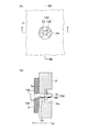
図1に示すように、組み立て連結具1は、黒鉛治具(第1治具)2と、黒鉛治具2の下面に取り付けられた複数の黒鉛治具(第2治具)3と、黒鉛治具2,3を固定する連結具150とを有する。図2(a),(b)に示すように、連結具150は、黒鉛治具固定用ピン(治具固定用ピン)100とE形リング(止め具)10とを有する。図1,2に示すように、黒鉛治具2は、上面に複数の凹部2aが形成された1枚の平板状の治具である。複数の凹部2aは、全て略同形状のものであり、所定の間隔だけ離れて略格子状に配列されている。また、図2(a)に示すように、凹部2aは、上方からみた断面が略円形状に形成されている。黒鉛治具3は、黒鉛治具2より小さな平板状の治具である。図2(b)に示すように、黒鉛治具3は、黒鉛治具2の凹部2aの下方に配置されている。また、黒鉛治具3は、黒鉛治具2の下面に連結具150により固定されている。
(Assembly connector 1)
As shown in FIG. 1, the assembly connector 1 includes a graphite jig (first jig) 2, a plurality of graphite jigs (second jigs) 3 attached to the lower surface of the
図2(b)に示すように、黒鉛治具2には、凹部2aと、凹部2aの底面の一部から黒鉛治具2の下面まで凹部2aの深さ方向(黒鉛治具2の厚み方向)に貫通した孔(第1貫通孔)2bとが形成されている。孔2bの外径は凹部2aの外径(幅)より小さく、凹部2a及び孔2bにより、黒鉛治具2には厚み方向に貫通した階段状の貫通孔が形成されている。また、黒鉛治具3には、厚み方向に貫通した孔(第2貫通孔)3aが形成されている。孔3aは、孔2bと略同外径の孔である。黒鉛治具3は、孔2b,3aが連通するように、黒鉛治具2の下方に配置されている。
As shown in FIG. 2B, the
図2(a)に示すように、本実施の形態において、凹部2aは、上方からみたときの断面がE形リング10の外周よりわずかに大きな円形状に形成されている。凹部2a内にE形リング10を配置させると、凹部2a内には、凹部2aの内側面とE形リング10の外側面との間に隙間がほとんど存在しない。したがって、E形リング10をスライド方向(凹部2aの幅方向)にほとんど移動させることができない。
As shown in FIG. 2A, in the present embodiment, the
孔2b,3aは、後述する黒鉛治具固定用ピン100の軸101の外径よりわずかに大きな外径に形成されている。さらに、孔2b,3aの外径は、黒鉛治具固定用ピン100の頭部102の外径より小さいとともに、E形リング10の外径より小さい。なお、本実施の形態において、孔2b,3aは略同外径であるが、孔2b,3aの外径が互いに異なっていてもよい。
The
黒鉛治具2,3は、黒鉛を含んでおり、環境(温度など)の変化に影響を受けにくい。なお、黒鉛治具2,3の形状は、図1に示す形状に限られず、異なる形状に形成されていてもよい。 The graphite jigs 2 and 3 contain graphite and are not easily affected by changes in the environment (temperature, etc.). The shape of the graphite jigs 2 and 3 is not limited to the shape shown in FIG. 1 and may be formed in different shapes.
(連結具150)
連結具150は、上述したように、黒鉛治具固定用ピン100とE形リング10とを有している。図2(b)に示すように、黒鉛治具2に形成された凹部2a内において、E形リング10が黒鉛治具固定用ピン100に装着される。これにより、黒鉛治具2,3が連結具150により上下方向から互いに固定される。
(Connector 150)
As described above, the
(黒鉛治具固定用ピン100)
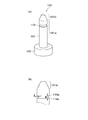
図3(a)に示すように、黒鉛治具固定用ピン100は、上下方向に延在した軸(挿入軸)101と、軸101の基端に設けられた円板状の頭部102とを有する。頭部102は、軸101の外径より大きな外径の円板であり、黒鉛治具2,3を、黒鉛治具3側(下方)から保持する(図2(b))。軸101及び頭部102は、各々の中心が一致するように接合されている。なお、各々の中心は仕様等に合せてずらしてもよく、必ずしも一致させる必要はない。軸101は、黒鉛治具固定用ピン100の基端側に位置する円柱状の第1領域101aと、第1領域101aよりも黒鉛治具固定用ピン100の先端側に位置するテーパー形状の第2領域101bとを有する。
(Graphite jig fixing pin 100)
As shown in FIG. 3A, the graphite
なお、本実施の形態において、第1領域101aは、軸101の長手方向について基端から先端に向けて約4分の3の長さの領域であり、第2領域101bは、残りの領域、すなわち、軸101の長手方向について先端から基端に向けて約4分の1の長さの領域である。第2領域101bは、軸101の先端に向けて先細りとなっており、第1領域101aと第2領域101bとは外径が連続して接続されている。
In the present embodiment, the
第1領域101aの先端側(第2領域101b側)の側面には、外周面に沿って環状の溝110が形成されている。図3(a),(b)に示すように、溝110は、軸101の長手方向に関する断面が略コの字状に形成されている。溝110の幅(軸101の長手方向に関する幅(図3(b)に示す距離B))は、E形リング10の厚み(図5(a)に示すLt)よりわずかに厚い。また、溝110の深さ(軸101の径方向に関する深さ(図3(b)に示す距離A))は、0.05mm以上であり且つ0.3mm未満である。溝110の最底部110cの外径は、E形リング10の穴径と同外径又はE形リング10の穴径よりわずかに大きな外径である。ここで、穴径とは、E形リング10の中央付近に形成された穴の内径である。具体的には、図4に示す3つの突起(係止部)12に接する最大円の直径dである。このような形状の溝110にE形リング10を嵌めると、E形リング10は、穴径が変化していない状態(E形リング10が周方向に広がったり、縮小したりしていない状態)又は穴径が僅かに大きくなった状態(E形リング10が周方向に僅かに拡径した状態)で、溝110に係合する。
An
次に、図5を参照しつつ、E形リング10と黒鉛治具2,3との関係を説明する。図5(a)には、本実施形態に係る組み立て連結具を示しており、図5(b)には、参考例に係る組み立て連結具を示している。
Next, the relationship between the
本実施の形態に係る黒鉛治具固定用ピン100の軸101は、図5(a)に示すように、E形リング10と黒鉛治具2,3との関係において、下記の式が成立する。
Ly+Lz+Lt≦Lp<Lx+Ly+Lz+Lt
ここで、
Lp:軸101の長手方向に関して軸101の基端から溝110の上端(軸101の先端側に位置する溝110の一端(上側面の縁110a))までの長さ
Lx:凹部2aの深さ方向に関する長さ
Ly:孔(第1貫通孔)2bの長手方向(深さ方向)に関する長さ
Lz:孔(第2貫通孔)3aの長手方向(深さ方向)に関する長さ
Lt:E形リング10の厚み
である。
上述の軸101の長さを有する黒鉛治具固定用ピン100を用いて黒鉛治具3を黒鉛治具2に対して固定すると、凹部2a内において、E形リング10が溝110に係合する。
As shown in FIG. 5A, the
Ly + Lz + Lt ≦ Lp <Lx + Ly + Lz + Lt
here,
Lp: length from the base end of the
When the
次に、図5(b)を用いて、参考例を説明する。図5(b)に示す黒鉛治具固定用ピン600は、軸601と、軸601の基端に設けられた頭部602とを有する。軸601の先端部は、軸101と同様に、先端に向けて先細りのテーパー状に形成されている。また、軸601には、軸101と同様な溝610が形成されている。図5(b)に示すように、Lp≧Lx+Ly+Lz+Ltのときは(Lp=Lx+Ly+Lz+Lt+Lcのとき)、凹部2a外において、E形リング10が黒鉛治具固定用ピン600に装着されるため、E形リング10をスライド移動させることにより黒鉛治具固定用ピン600から取り外すことができる。また、図示しないが、Lp<Ly+Lz+Ltのときは、溝110の一部若しくは全部が凹部2aより下方に位置するため、凹部2a内においてE形リング10を溝110に完全に係合させることができない。E形リング10が溝110に完全に係合しない場合、意図しない衝撃によって溝110から外れるといった不具合を生じる。
Next, a reference example will be described with reference to FIG. A graphite
また、連結具150により黒鉛治具2,3を固定したとき、黒鉛治具固定用ピン100の長手方向に関する凹部2aの底面からE形リング10の底面までの距離Lbが、約0.3mm未満であることが好ましい。距離Lbが0.3mm以上である場合、頭部102とE形リング10との間に生じるあそびが大きくなり、連結具150により黒鉛治具2及び黒鉛治具3を固定した際に黒鉛冶具2と黒鉛冶具3の密着性を保持することができないおそれがある。
When the graphite jigs 2 and 3 are fixed by the connecting
さらに、溝110の深さ(図3(b)に示す距離A)を0.05mm以上0.3mm未満とすることにより、凹部2a内において、溝110に係合したE形リング10に対して、黒鉛治具固定用ピン100の先端を人の力(約47N以上57N以下)で動かした道具により押圧することによって、E形リング(止め具)の径を周方向に拡径し簡易に脱着することができる。すなわち、上記溝110の深さにすることによって、道具を用いて人の力を加えることにより簡易にE形リング10を溝110から外すことができる。なお、溝110の深さが0.3mm以上である場合、溝110が深いため、E形リング10が溝110に強固に係合するものの、人の力で動かした道具による押圧ではE型リング(止め具)の径を黒鉛冶具固定用ピンから外れる程度にまで周方向に拡径できないことがあるため、E形リング10を黒鉛治具固定用ピン100から取り外すときに、ペンチ等の道具を用いてE形リング10を変形させることが必要となる。そのため、E形リング10を黒鉛治具固定用ピン100から簡易に取り外すことができない。また、E形リング10が本来の形状から変形しているため、再利用することができない。一方、溝110の深さが0.05mm未満であると、溝110が浅いため、E形リング10を溝110へ係合させてもE形リング10が溝110から外れやすくなる。そのため、黒鉛治具2,3を強固に固定することができず、電子部品の組立作業中にE形リング10が黒鉛治具固定用ピン100から外れてしまうことがある。なお、溝110の深さ(距離A)は、0.05mm以上且つ0.15mm未満であることがさらに好ましい。溝110の深さが、0.15mm未満の場合は、黒鉛治具2,3を確実に固定することができ、且つ、より小さな力により、E形リング10の黒鉛治具固定用ピン100への着脱が可能となる。したがって、E形リング10の黒鉛治具固定用ピン100への着脱回数が多い場合に、作業効率を向上させることができる。
Furthermore, by setting the depth of the groove 110 (distance A shown in FIG. 3B) to 0.05 mm or more and less than 0.3 mm, the
ここで、本実施の形態における「溝110の深さ」とは、軸101の径方向に関して、溝110の開口から最底部110cまでの距離Aである(図3(b))。また、本実施の形態において、図3(b)に示す縁110aは、軸101の最大外径(第1領域101aの外径及び第2領域101bの最大外径と同外径)となっている。ここで、縁110aは、軸101の先端側に位置する溝110の縁(溝110の上側面の縁110a)である。なお、軸101の溝110より先端側の領域に、縁110aの外径より大きな外径の領域は存在しない。軸101の溝110より先端側に、縁110aより大きな外径の領域が存在する場合、E形リング10を黒鉛治具固定用ピン100から取り外すために、E形リング10を壊したり変形したりすることが必要となる。また、本実施の形態における「最底部110c」は、溝110の底面のうち軸101の中心に最も近い位置である。
Here, the “depth of the
なお、本実施の形態における溝110は、深さ方向に関する断面(軸101の長手方向に関する断面)が略コの字状に形成されているが、溝110の断面はコの字状に限られない。例えば、溝110を、底部に丸みを帯びた略U字状の断面の溝に形成してもよく、溝の幅が底から溝の深さ方向に大きくなるV字状の断面の溝としてもよい。
The
また、溝110が形成される位置は、図3(a)に示すような第1領域101aの先端側に限られず、黒鉛治具2,3の厚みなどに合わせて適宜変更することができる。例えば、溝110を図3(a)に示すよりも軸101の基端側に形成してもよく、また、溝110を図3(a)に示すよりも軸101の先端側に形成し、溝110の開口(縁110a)と第2領域101bとが連続してもよい。
Further, the position where the
黒鉛治具固定用ピン100は、鉄、鋼又はステンレス(SUS)などが用いられている。また、軸101は、図2,3に示す形状に限られず、例えば、第1領域101aの外径が約1.6mm〜5mmであり且つ第1領域101aの長手方向の長さが約3.0〜30.0mmである軸を用いることができる。なお、第1領域101a及び第2領域101bの長手方向に関する比率は、図3(a)に示す3:1の比率に限られない。例えば、第1領域101aの長手方向に関する長さを短くしたり、第2領域101bを軸101の長手方向にさらに延在させたりしてもよい。また、第2領域101bのテーパー形状は、図3(a)に示す形状より傾斜が緩やかなテーパー形状としてもよく、図3(a)に示す形状より鋭角のテーパー形状としてもよい。なお、黒鉛治具固定用ピン100は、上述の材料及び形状などに限定されず、他の材料や異なる形状の黒鉛冶具固定用ピンを用いてもよい。また、頭部102の形状、軸101の長さ及び軸101の径などは、黒鉛治具2,3の形状、孔2b,3aの長手方向に関する長さ及び凹部2aの深さ(高さ)に合わせて、適宜変更させることができる。
The graphite
(E形リング10)
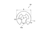
図4に示すように、非環状のE形リング10は、ステンレス素材からなり、略C形の支持部11と、支持部11の内側面に形成された3つの突起(係止部)12とを有する。E形リング10の中央付近には、3つの突起(係止部)12に包囲された穴が形成されており、軸101がこの穴に挿通する。支持部11の両端の間には、穴と連通した隙間10aが存在し、隙間10aによりE形リング10は穴の周方向に広がったり縮小したりして、穴の径が変化する。3つの突起(係止部)12は、支持部11の内側部に2箇所の凹みを形成することにより、支持部11の両端及び中央付近に形成されている。
(E-shaped ring 10)
As shown in FIG. 4, the non-annular
本実施形態では、例えば、以下の径を有するE形リング(JIS B 2805 1.5(硬さがHRC44〜53であり、バネ用ステンレス鋼からなるE形リング))を用いることができる。なお、以下に示す記号(d,D,H)は、図4に示す記号である。
d:1.5cm
D:4.0cm
H:1.3cm
E形リングの厚み:0.4cm
また、上記E形リング10には、外径が1.53cmの軸を有するピンを適用することができる。
In this embodiment, for example, an E-shaped ring (JIS B 2805 1.5 (E-shaped ring having hardness of HRC44-53 and made of spring stainless steel) having the following diameter can be used. The symbols (d, D, H) shown below are the symbols shown in FIG.
d: 1.5cm
D: 4.0cm
H: 1.3cm
E-shaped ring thickness: 0.4cm
Further, a pin having an axis having an outer diameter of 1.53 cm can be applied to the
E形リング10を黒鉛治具固定用ピン100に装着すると、図2(a)に示すように、3つの突起(係止部)が軸101を挟持する。このとき、E形リング10は溝110の全周面を周方向に取り囲まない。
When the
また、図4に示すE形リング10の穴径(内径(図4に示すd))が、黒鉛治具固定用ピン100の軸101の溝110が形成されていない部分の直径より小さく、且つ、軸101の溝110が形成された部分の直径から0.1mmを差し引いた値以上の範囲内に属している。さらに、E形リング10が装着される黒鉛治具固定用ピン100の溝110の深さ(図3(b)に示す距離A)が0.05mm以上であり且つ0.3mm未満となっている。これにより、E形リング10の突起12の内周面と軸101の溝110が形成された部分との隙間が生じすぎない。したがって、E形リング10が黒鉛治具固定用ピン100の軸101の径方向について一方向に偏らない。よって、黒鉛冶具固定用ピン100またはE形リング10を押圧した際に、E形リング10全体に対して平均的に応力がかかるようにE形リング10を押圧することができ、E形リング10の一部に応力が集中するのを防ぐことができる。
Moreover, the hole diameter (inner diameter (d shown in FIG. 4)) of the
なお、隙間10aは、図4に示す隙間10aの大きさに限られない。例えば、支持部11の両端を周方向にさらに延在させ、隙間10aを、わずかな隙間としてもよい。このように、連結具150を構成する止め具(E形リング10)は、非環状の止め具であることが好ましい。止め具として環状の止め具を用いる場合、溝110は周方向に取り囲まれるが、黒鉛冶具固定用ピンへの装着時に止め具に外力が加えられたとしても止め具の外径(穴径)がほとんど変化しないため、止め具を溝110から外すときにプッシュナットと同様に止め具を変形させることが必要となる。一方、本願のE形リング10においては、E形リング10に外力による応力が掛かると、隙間10aが穴の周方向に広がり、それに伴いE形リング10が変形しない程度に簡易に拡径する。よって、E形リング10を変形させることなく簡易に溝110から取り外すことができる。なお、E形リング10の穴径は、軸101と略同外径又は軸101の外径よりわずかに小さな外径であることが好ましい。ここでいう「変形」とは、力を加えた際に一時的に形状を変化したものではなく、力を加え終わった後も初期形状に戻らなくなった状態を指す。本事項は、止め具に用いられる素材を考慮して実施者が適宜決定すればよい。
The
図2(b)に示すように、E形リング10は、黒鉛治具2,3を黒鉛治具2側(上方)から固定する。E形リング10は、例えば、ステンレス、鋼などからなるものを使用することができるが、止め具の材料はこれらの材料に限定されない。また、連結具150を構成する止め具(E形リング10)には、黒鉛治具固定用ピン100の大きさや形状に合う止め具を用いてよい。例えば、軸101の外径及び溝110の外径に合わせて異なる大きさの穴径の止め具や図4に示す支持部11と異なる形状の支持部を有する止め具を用いてもよい。さらに、止め具は、E形リング10に限られず、後述するC形リングなどの非環状の止め具を用いてもよい。
As shown in FIG. 2B, the
本実施形態のE形リング10は、ステンレス素材からなり変形しにくい。そして、E形リング10の許容スラスト荷重が70(N)以上500(N)以下である。許容スラスト荷重が70(N)未満であるときは、E形リング10を黒鉛治具固定用ピン100から着脱する際に無理な押圧を行ったときにE形リング10が変形してしまう可能性がある。また、許容スラス荷重が500(N)を超える場合は、道具を用いて約47(N)以上57(N)以下の人の力を加えても止め具の径を大きくすることは適わない。このように、本実施形態においては、止め具に一般的に用いられている内径を有する孔を備え且つステンレス素材からなるE形リング10が用いられる。なお、E形リング10の許容スラスト荷重は100(N)以上300(N)以下であることがより好ましい。
The
(E形リング10を黒鉛治具固定用ピン100に装着する方法)
黒鉛治具2,3を孔2b,3aの各々が連通するように積層し、黒鉛治具固定用ピン100の軸101を、黒鉛治具3側から、連通した孔2b,3aへ挿入する。そして、E形リング10を、黒鉛治具2側に配置された軸101の先端からスラスト方向(軸101の長手方向)に押圧する。ここで、押圧の力は人の力(約47(N)以上57(N)以下)でよい。なお、E形リング10を押圧する作業は細かい作業のため、E形リング10だけを押圧出来る様な道具を用いることが好ましい。これにより、E形リング10は、その穴径(図4に示すd)がわずかに大きくなりながら、スラスト方向(軸101の長手方向)に移動して溝110に嵌まる。なお、E形リング10を黒鉛治具固定用ピン100に装着する際、E型リング10は隙間10aに合わせて傾斜した第2領域101bに密着するため、E形リング10に均等に力が掛かる。黒鉛治具固定用ピン100に装着されたE形リング10は、溝110の全周面を周方向に取り囲んでおらず、穴径がわずかに大きくなった状態(溝110の周方向に(外側に)僅かに広がった状態)又は穴径が殆ど変化していない状態(溝110の周方向に殆ど広がったり縮小したりしていない状態)で溝110に係合している(図2(a),(b))。
(Method of mounting the E-ring 10 to the graphite jig fixing pin 100)
The graphite jigs 2 and 3 are laminated so that the
(E形リング10を黒鉛治具固定用ピン100から取り外す方法)
図2(a),(b)に示す状態から、黒鉛治具固定用ピン100の先端に、スラスト方向(軸101の長手方向)に力を加える。この際、黒鉛治具固定用ピン100だけを押圧出来る円柱形の様な道具を用いることが好ましく、前記円柱形状冶具の黒鉛冶具固定用ピン100への押圧の力は、E形リング10を黒鉛治具固定用ピン100に装着するときに加える力と略同じ人の力(約47(N)以上57(N)以下)でよい。E形リング10に力が加えられたら、黒鉛治具固定用ピン100は基端側へ移動し、溝110の側壁(上側面)がE形リング10を押圧する。これにより、E形リング10の隙間10aが周方向(外側)に広がり、E形リング10の穴径(図4に示すd)が、溝110の縁110aの外径と略同外径又は縁110aの外径より僅かに大きくなる。そして、E形リング10が溝110から外れ、E形リング10は黒鉛治具固定用ピン100の先端側へ移動する。
(Method for removing E-ring 10 from graphite jig fixing pin 100)
From the state shown in FIGS. 2A and 2B, force is applied to the tip of the graphite
以上のように、本実施の形態の組み立て連結具1によると、下記の効果を奏する。E形リング10が、黒鉛冶具固定用ピン100への溝110を周方向に完全に取り囲まない状態で係合する非環状部材であるため、止め具の許容スラスト荷重が70(N)以上500(N)以下でも、黒鉛冶具固定用ピン100のスラスト方向に止め具を脱着するために黒鉛冶具固定用ピン100やE形リング10を押圧した際、E形リング10に大きな応力を掛けることなく、E形リング10の径を拡張することができる。また、E形リング10の径が拡張しても、E形リング10が大きく変形しにくいため、使用後のE形リング10を再使用することができる。
As described above, the assembly connector 1 of the present embodiment has the following effects. Since the
また、図5(a)に示すように、E形リング10と黒鉛治具2,3との関係において、下記の式が成立することから、黒鉛治具2の凹部2a内において、E形リング10を黒鉛冶具固定用ピン100に対してスラスト方向に移動させることにより、E形リング10を黒鉛治具固定用ピン100から簡易に着脱することができる。
Ly+Lz+Lt≦Lp<Lx+Ly+Lz+Lt
Further, as shown in FIG. 5 (a), the following formula is established in relation to the
Ly + Lz + Lt ≦ Lp <Lx + Ly + Lz + Lt
さらに、黒鉛冶具固定用ピン100の溝110の深さが0.05mm以上であることによって、E形リング10を黒鉛冶具固定用ピン100の軸101の溝110に確実に装着することができる。また、溝110の深さが0.3mm未満であることによって、E形リング10を黒鉛治具固定用ピン100からより簡易に着脱することができる。
Furthermore, when the depth of the
加えて、E形リング10の内径は、黒鉛冶具固定用ピン100の軸101の直径より小さく、且つ、黒鉛冶具固定用ピン100の溝110の直径から0.1mmを差し引いた値の範囲内に属していることから、E形リング10を黒鉛冶具固定用ピン100の軸101の溝110に対して外方へ張り出すように大きく拡径した状態で装着することを避けることができる。また、E形リング10の内周面と軸101の溝110の周面との隙間があまり生じないことから、E形リング10の拡径が黒鉛冶具固定用ピン100の軸101の径方向について一方向に偏らない。よって、黒鉛冶具固定用ピン100やE形リング10を押圧した際に、効率よくE形リング10全体に均等に応力がかかり、黒鉛冶具固定用ピン100の内径を軸101の外形と同等になる程度まで拡径できるため、E形リング10を黒鉛治具固定用ピン100から簡易に着脱することができる。
In addition, the inner diameter of the
また、黒鉛冶具固定用ピン100の軸101が先端に向けて先細りのテーパー形状であるため、E形リング10が傾斜した軸101に略等しく密着する。そのため、E形リング10全体に均等に応力をかけることができる。これにより、E形リング10を黒鉛治具固定用ピン100により簡易に装着することができる。
In addition, since the
なお、本実施形態では、溝110の側壁が、軸101の径方向に延在しているが、溝110の開口が溝110の底面より大きくなるように、溝110の側壁のうち軸101の先端側に位置する側壁を、軸101の先端に向けて緩やかに傾斜させてもよい。これにより、E形リング10を溝110からより簡易に取り外すことができる。
In the present embodiment, the side wall of the
以上、本発明の好適な実施形態について説明したが、本発明は上述の実施の形態に限られるものではなく、特許請求の範囲に記載した限りにおいて様々な変更が可能なものである。例えば、上述の実施の形態で説明した黒鉛治具固定用ピン100、E形リング10及び黒鉛治具2,3の形状や材料は一例であり、固定用ピン、止め具及び治具に異なる形状のものや異なる材料を用いてもよい。
The preferred embodiments of the present invention have been described above, but the present invention is not limited to the above-described embodiments, and various modifications can be made as long as they are described in the claims. For example, the shapes and materials of the graphite
次に、本実施形態に係る組み立て連結具の変形例を説明する。以下の変形例において、本発明の第1実施形態と同様なものに関しては、同符号で示し、説明を省略する。また、以下の変形例における黒鉛治具固定用ピン及び止め具にも、上述の第1実施形態における黒鉛治具固定用ピン100及びE形リング10と同様な材料を用いることができる。
Next, a modification of the assembly connector according to this embodiment will be described. In the following modifications, the same components as those in the first embodiment of the present invention are denoted by the same reference numerals and description thereof is omitted. In addition, the same material as the graphite
<変形例1>
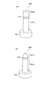
変形例1に係る組み立て連結具は、黒鉛治具固定用ピンの形状において、本実施形態に係る組み立て連結具と異なる。なお、変形例1に係る組み立て連結具のその他の構成は、本実施形態の組み立て連結具の構成と同様であるため、説明を省略する。図6(a)に示す黒鉛治具固定用ピン200は、第1実施形態における第2領域101bの代わりに、円柱状の第2領域201bを有している。第2領域201bは、第1領域101aと同外径の円柱である。
<Modification 1>
The assembly connector according to Modification 1 is different from the assembly connector according to the present embodiment in the shape of the graphite jig fixing pin. In addition, since the other structure of the assembly coupling tool which concerns on the modification 1 is the same as that of the assembly coupling tool of this embodiment, description is abbreviate | omitted. A graphite
<変形例2>
変形例2に係る組み立て連結具は、黒鉛治具固定用ピンの形状において、本実施形態に係る組み立て連結具と異なる。なお、変形例2に係る組み立て連結具のその他の構成は、本実施形態の組み立て連結具の構成と同様であるため、説明を省略する。図6(b)に示す黒鉛治具固定用ピン300は、第1実施形態における第1領域101aの代わりに、第1領域301aを有している。第1領域301aにおいて、溝110は第1領域301aの先端に形成されている。この位置に溝110が形成されることにより、溝110と第2領域101bの基端とが連続している。
<
The assembly connector according to
変形例1,2に係る組み立て連結具によっても、本実施形態と同様な効果を得ることができる。なお、第2領域201bは、テーパー状に形成されていてもよい。
Effects similar to those of the present embodiment can also be obtained by the assembly connector according to the first and second modifications. Note that the
また、本実施形態及び変形例にかかる第2領域101bは、截頭円錐状に形成されているが、円錐状に形成されていてもよい。
Moreover, although the 2nd area |
<変形例3>
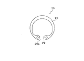
変形例3に係る組み立て連結具は、止め具の形状(E形リングの代わりにC形止め輪を用いている点)において、本実施形態に係る組み立て連結具と異なる。なお、変形例3に係る組み立て連結具のその他の構成は、本実施形態の組み立て連結具の構成と同様であるため、説明を省略する。図7に示すように、C形止め輪20は、第1実施形態におけるE形リング10と同様な非環状部材であって、略C形の支持部21と、支持部21の両端のそれぞれに設けられた保持部22とを有する。また、支持部21の内側面に凹凸が形成されていない。また、支持部21に包囲された穴に黒鉛治具固定用ピンの軸が挿通する。支持部21の両端の間には、第1実施形態におけるE形リング10と同様に、穴と連通した隙間20aが存在する。C形止め輪20は、隙間20aにより穴の周方向に広がったり縮小したりし、これにより穴の径が変化する。保持部22は、C形止め輪20(穴)の中心に向けて突出した凸形状を有している。
<
The assembly connector according to
C形止め輪20を黒鉛治具固定用ピンに形成された溝に係合させると、支持部21の中央付近及び2つの保持部22が軸101を径方向に挟持する。このとき、C形止め輪20は、溝の全周面を周方向に取り囲まない。
When the C-shaped
本変形例に係るC形止め輪20をE形リング10の代わりに用いた連結具によっても、第1実施形態と同様の効果が得られる。また、止め具は、E形リング10及びC形止め輪20に限られず、丸S形止め輪、丸R形止め輪及びベベル形止め輪などの非環状の止め具を用いてもよい。
The same effect as that of the first embodiment can also be obtained by a connector using the C-shaped
また、本実施形態及び本変形例における黒鉛治具固定用ピン100,200,300は、溝110より基端側の領域が円柱形状であるが、溝110より基端側の領域をテーパー状に形成してもよい。
Further, in the graphite jig fixing pins 100, 200, and 300 in this embodiment and this modification, the proximal end region from the
さらに、本実施の形態及び本変形例に係る連結具150は、2つの黒鉛治具2,3を固定するために用いられているが、3つ以上の黒鉛治具を固定するために用いられてもよい。例えば、黒鉛治具2及び黒鉛治具3の間にさらに異なる黒鉛治具を配置させたり、黒鉛治具3の下方にさらに異なる黒鉛治具を配置させたりしてもよい。
Further, the
1 組み立て連結具
2 黒鉛治具(第1治具)
2a 凹部
2b 孔(第1貫通孔)
3 黒鉛治具(第2治具)
3a 孔(第2貫通孔)
10 E形リング(止め具)
20 C形止め輪(止め具)
10a,20a 隙間
100,200,300 黒鉛治具固定用ピン(治具固定用ピン)
110 溝
101a,301a 第1領域
101b,201b 第2領域
150 連結具
1
3 Graphite jig (second jig)
3a hole (second through hole)
10 E-shaped ring (stopper)
20 C-type retaining ring (stopper)
10a,
110 groove |
Claims (5)
第2貫通孔を有する第2治具と、
前記第1治具及び前記第2治具を互いに固定する連結具とを備えた組み立て連結具において、
前記連結具は、前記第1貫通孔と前記第2貫通孔とに挿通する治具固定用ピンと、前記凹部内において前記治具固定用ピンに係合する止め具とを有しており、
前記治具固定用ピンは、挿入軸と、前記挿入軸の基端に前記第2貫通孔の径より大きな頭部とを有しており、
前記挿入軸の周面に沿って環状の溝が形成されており、
前記止め具は、前記溝を周方向に完全に取り囲まない状態で係合する非環状部材であり、
前記止め具は金属素材からなり、且つ、前記止め具の許容スラスト荷重が70(N)以上500(N)以下であることを特徴とする組み立て連結具。 A first jig having a recess formed in a predetermined surface and a first through hole in a part of the bottom surface of the recess;
A second jig having a second through hole;
In an assembly connector comprising a connector for fixing the first jig and the second jig to each other,
The connector has a jig fixing pin inserted into the first through hole and the second through hole, and a stopper engaged with the jig fixing pin in the recess,
The jig fixing pin has an insertion shaft and a head larger than the diameter of the second through hole at the base end of the insertion shaft,
An annular groove is formed along the peripheral surface of the insertion shaft,
The stopper is a non-annular member that engages the groove without completely surrounding the groove in the circumferential direction;
The assembly connecting tool, wherein the stopper is made of a metal material, and an allowable thrust load of the stopper is 70 (N) or more and 500 (N) or less.
Ly+Lz+Lt≦Lp<Lx+Ly+Lz+Lt・・・(1)
ここで、
Lp:前記挿入軸の長手方向に関して前記挿入軸の基端から前記挿入軸の先端側に位置する前記溝の一端までの長さ
Lx:前記凹部の深さ方向に関する長さ
Ly:前記第1貫通孔の深さ方向に関する長さ
Lz:前記第2貫通孔の深さ方向に関する長さ
Lt:前記止め具の厚み The assembly coupling tool according to claim 1, wherein the jig fixing pin and the stopper satisfy the following expression (1).
Ly + Lz + Lt ≦ Lp <Lx + Ly + Lz + Lt (1)
here,
Lp: length from the proximal end of the insertion shaft to one end of the groove located on the distal end side of the insertion shaft in the longitudinal direction of the insertion shaft Lx: length in the depth direction of the recess Ly: the first penetration Length in the depth direction of the hole Lz: Length in the depth direction of the second through hole Lt: Thickness of the stopper
Priority Applications (3)
| Application Number | Priority Date | Filing Date | Title |
|---|---|---|---|
| JP2011120786A JP5777205B2 (en) | 2011-05-30 | 2011-05-30 | Assembly coupler |
| PCT/JP2012/063929 WO2012165478A1 (en) | 2011-05-30 | 2012-05-30 | Assembly linking fixture |
| CN201280026608.0A CN103563506B (en) | 2011-05-30 | 2012-05-30 | Assembly and connection instrument |
Applications Claiming Priority (1)
| Application Number | Priority Date | Filing Date | Title |
|---|---|---|---|
| JP2011120786A JP5777205B2 (en) | 2011-05-30 | 2011-05-30 | Assembly coupler |
Publications (3)
| Publication Number | Publication Date |
|---|---|
| JP2012247031A JP2012247031A (en) | 2012-12-13 |
| JP2012247031A6 true JP2012247031A6 (en) | 2013-10-03 |
| JP5777205B2 JP5777205B2 (en) | 2015-09-09 |
Family
ID=47259330
Family Applications (1)
| Application Number | Title | Priority Date | Filing Date |
|---|---|---|---|
| JP2011120786A Active JP5777205B2 (en) | 2011-05-30 | 2011-05-30 | Assembly coupler |
Country Status (3)
| Country | Link |
|---|---|
| JP (1) | JP5777205B2 (en) |
| CN (1) | CN103563506B (en) |
| WO (1) | WO2012165478A1 (en) |
Families Citing this family (3)
| Publication number | Priority date | Publication date | Assignee | Title |
|---|---|---|---|---|
| CN104343789B (en) * | 2013-08-08 | 2016-03-16 | 北大方正集团有限公司 | A kind of contraposition pin |
| JP5960233B2 (en) * | 2014-11-28 | 2016-08-02 | 中国電力株式会社 | Indirect hot line cotter and indirect hot wire adapter |
| CN106193845B (en) * | 2015-04-30 | 2019-02-05 | 开开特股份公司 | Motor vehicle lock shell with pawl |
Family Cites Families (7)
| Publication number | Priority date | Publication date | Assignee | Title |
|---|---|---|---|---|
| JP2544057Y2 (en) * | 1987-12-14 | 1997-08-13 | パイオニア株式会社 | E-ring for capstan of cassette tape player |
| JP2003278726A (en) * | 2002-03-26 | 2003-10-02 | Canon Inc | Fastener for d-cut shaft |
| JP3756909B2 (en) * | 2003-11-14 | 2006-03-22 | 均 西谷 | Hinge device |
| JP2008241751A (en) * | 2007-03-23 | 2008-10-09 | Ricoh Co Ltd | Developing roller and developing device |
| JP2009068585A (en) * | 2007-09-12 | 2009-04-02 | Heiwa Corp | Connection structure |
| JP5940244B2 (en) * | 2008-07-17 | 2016-06-29 | デンカ株式会社 | Aluminum-diamond composite and method for producing the same |
| JP2010189890A (en) * | 2009-02-17 | 2010-09-02 | Chugoku Electric Power Co Inc:The | Walk assist plate |
-
2011
- 2011-05-30 JP JP2011120786A patent/JP5777205B2/en active Active
-
2012
- 2012-05-30 WO PCT/JP2012/063929 patent/WO2012165478A1/en active Application Filing
- 2012-05-30 CN CN201280026608.0A patent/CN103563506B/en not_active Expired - Fee Related
Similar Documents
| Publication | Publication Date | Title |
|---|---|---|
| US9039318B2 (en) | Component connection comprising a first and a second component and a male and a female fixing element | |
| JP6041189B2 (en) | Snap ring mounting jig | |
| CN101311560B (en) | Coupling assembly and coupling method thereof | |
| JP2013024423A (en) | Functional element having rotation prevention function, and component assembly having functional element and sheet metal member | |
| JP5777205B2 (en) | Assembly coupler | |
| JP2006207625A (en) | Disc pad | |
| JP2012247031A6 (en) | Assembly coupler | |
| JP2008130564A (en) | Press-fit pin and manufacturing method therefor | |
| JP2016096215A (en) | Semiconductor device and manufacturing method of the same | |
| JP4920275B2 (en) | Plate member fastening method and fastening structure | |
| JP2022001782A5 (en) | ||
| JP4807684B1 (en) | Fastener | |
| JP6186271B2 (en) | Lower member fixing device and fluid control device including the same | |
| JP2019173876A (en) | Collar and collar attaching method | |
| JP2013116527A (en) | Mounting tool of snap ring | |
| JP2008220458A (en) | Bathtub unit | |
| JP2012110922A (en) | Mold structure | |
| JP6132515B2 (en) | Manufacturing method of joint member with nut | |
| JP2007160366A (en) | Caulking tool and caulking method | |
| JP4849809B2 (en) | Height adjuster | |
| JP3143575U (en) | Fasteners and molded parts | |
| JP6875632B2 (en) | Structure and manufacturing method of structure | |
| KR20180133331A (en) | Electrical contact assembly | |
| JP2007103117A (en) | Guide pin for electric connector | |
| JP3155923U (en) | Hole punch for hot forging |