JP2012246677A - Flat roof plate member - Google Patents
Flat roof plate member Download PDFInfo
- Publication number
- JP2012246677A JP2012246677A JP2011119210A JP2011119210A JP2012246677A JP 2012246677 A JP2012246677 A JP 2012246677A JP 2011119210 A JP2011119210 A JP 2011119210A JP 2011119210 A JP2011119210 A JP 2011119210A JP 2012246677 A JP2012246677 A JP 2012246677A
- Authority
- JP
- Japan
- Prior art keywords
- flat roof
- roof material
- hole
- flat
- fixing
- Prior art date
- Legal status (The legal status is an assumption and is not a legal conclusion. Google has not performed a legal analysis and makes no representation as to the accuracy of the status listed.)
- Granted
Links
Images


Abstract
Description
本発明は、家屋等の屋根上に葺かれる平板屋根材に関する。 The present invention relates to a flat roof material that is laid on a roof of a house or the like.
家屋等の建物の屋根30を形成するために使用される平板屋根材1は、図6(a)に示すように、野地板20の軒側(傾斜方向下側)から棟側(傾斜方向上側)に向かって、順次ラップするように重ね葺きされて施工される。特に風が強いような地域においては、平板屋根材1が強風によって、その傾斜方向の下側からめくれ上がることを防止するために、種々の方法が検討されている。
As shown in FIG. 6A, the
具体的には、図6(b)に示すように、まず、複数の釘穴40が形成された平板屋根材1を、軒側から棟側に向かって重ね葺きする。次いで、釘穴40を貫通するように、釘等の固定具3を野地板20へ向かって打入させる。さらに、強風地域においては、上側の平板屋根材1の釘穴40より軒側の位置に補強用ビス45を、下側の平板屋根材1を貫通するように打入させ、強風が吹き付けても平板屋根材1がめくり上がらないようにさせている。
Specifically, as shown in FIG. 6B, first, the
また、上記以外の方法にも種々検討されており、例えば、平板屋根材1表面にクリップを釘等で固定させて設け、このクリップに掛止させるように他の平板屋根材1を載置させることも開示されている(例えば、特許文献1を参照)。
Various methods other than the above have been studied. For example, a clip is fixed to the surface of the
しかし、図6のような方法で施工する場合、補強用ビス45を打ち込むための穴を、施工現場にてコンクリートドリル等で形成させる必要があったため、施工に手間がかかる上、平板屋根材1にひびや割れ等の破損が生じてしまうおそれもあった。また、補強用ビス45を打ち込むための穴を形成させた後、止水性を高めるために、防水シート等の止水材5を上側の平板屋根材1と下側の平板屋根材1との間に差し込む必要もあったので、さらに施工に手間がかかってしまう問題があった。
However, when it is constructed by the method as shown in FIG. 6, it is necessary to form a hole for driving the reinforcing
また、特許文献1のように平板屋根材1表面にクリップを設ける場合でも、クリップを釘等で固定する際に平板屋根材1が破損したりしてしまう問題や、構成部材も多くなってしまう問題もあった。
Further, even when a clip is provided on the surface of the
本発明は上記の点に鑑みてなされたものであり、重ね葺き施工時に釘穴等を形成する手間が省けると共に、平板屋根材の破損を抑制でき、施工性と安定性に優れる平板屋根材を提供することを目的とするものである。 The present invention has been made in view of the above points, and it is possible to eliminate the trouble of forming nail holes and the like at the time of laying, and to prevent the flat roof material from being damaged, and to provide a flat roof material excellent in workability and stability. It is intended to provide.
本発明に係る平板屋根材は、屋根の傾斜方向で重ね葺きされる平板屋根材において、前記平板屋根材は曝露部と非曝露部とを有し、前記傾斜方向で隣接する平板屋根材のうち、前記傾斜方向で下側に位置する平板屋根材の非曝露部の上に、前記傾斜方向で上側に位置する平板屋根材の曝露部が重ねられるようにして施工される平板屋根材であり、非曝露部には固定具を打入することができる複数の固定用穴が形成され、曝露部には固定具を打入することができる補強用穴が少なくとも一個以上形成され、重ね葺き施工したときに前記傾斜方向で上側に位置する平板屋根材の前記補強用穴と、前記傾斜方向で下側に位置する平板屋根材の前記固定用穴の少なくとも一つとが互いに重なって位置するように前記補強用穴が設けられていることを特徴とする。 The flat roof material according to the present invention is a flat roof material stacked and rolled in the inclination direction of the roof, wherein the flat roof material has an exposed portion and a non-exposed portion, and among the flat roof materials adjacent in the inclined direction. The flat roof material is constructed so that the exposed portion of the flat roof material located on the upper side in the inclined direction is overlaid on the non-exposed portion of the flat roof material located on the lower side in the inclined direction, A plurality of fixing holes into which the fixing tool can be inserted are formed in the non-exposed part, and at least one reinforcing hole into which the fixing tool can be input is formed in the exposed part. Sometimes the reinforcing hole of the flat roof material located on the upper side in the inclined direction and at least one of the fixing holes of the flat roof material located on the lower side in the inclined direction are positioned so as to overlap each other. Reinforcing holes are provided. To.
また、上記平板屋根材は、重ね葺き施工したときに前記補強用穴の下側に重なる前記固定用穴の面積が、前記補強用穴の面積よりも大きく形成されていることが好ましい。 Moreover, it is preferable that the said flat roof material is formed so that the area of the said fixing hole which overlaps the lower side of the said hole for reinforcement when it laps and constructs is larger than the area of the said hole for reinforcement.
また、上記平板屋根材は、重ね葺き施工したときに前記補強用穴の下側に重なる固定用穴には、その開口を閉塞するように止水材が設けられていることが好ましい。 Moreover, it is preferable that the said flat roof material is provided with the water stop material in the fixing hole which overlaps the lower side of the said hole for reinforcement when carrying out lap construction so that the opening may be obstruct | occluded.
本発明の平板屋根材は、重ね葺き施工時に釘穴等を形成する手間が省けると共に、平板屋根材の破損を抑制でき、施工性と安定性に優れる。 The flat roof material of the present invention saves labor for forming nail holes and the like at the time of laying, and can prevent the flat roof material from being damaged, and is excellent in workability and stability.
以下、本発明を実施するための形態を説明する。 Hereinafter, modes for carrying out the present invention will be described.
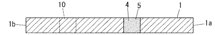
本発明の平板屋根材1は、図1(a)に示すように、平面視略矩形状で幅広の平板状に形成されるものであり、平板屋根材1の上片は棟側端部1a、下片は軒側端部1bとして形成されている。尚、平板屋根材1の形状は平面視略矩形状に限らず、その他の形状であっても良い。
As shown in FIG. 1 (a), the
そして、平板屋根材1は屋根30の傾斜方向に沿って重ね葺きされるものである。具体的には、図1(b)に示すように、傾斜方向の下側である軒側から、傾斜方向の上側である棟側に向かって上下に隣接させながら重ね葺きされて施工され、屋根30が形成される。この場合、平板屋根材1において棟側端部1aが傾斜方向の上側(棟側)、軒側端部1bが傾斜方向の下側(軒側)に位置するものとなる。尚、通常、平板屋根材1は野地板20等の表面に重ね葺きされていくものであるが、図では省略している。また、傾斜方向と直交する方向(平板屋根材1の左右方向)では、平板屋根材1の側端面どうしが突き合わされるように敷き詰められる。
And the
また、平板屋根材1は、曝露部6と、非曝露部7とを有するものである。曝露部6は、平板屋根材1が重ね葺きされたときに外部に露出している部分であり、非曝露部7は、平板屋根材1が重ね葺きされたときに重ね合わされて下側に位置し、外部には露出しない部分である。平板屋根材1において、曝露部6は、非曝露部7よりも下側(軒側)に位置している。
Further, the
屋根30の傾斜方向(以下、軒棟方向ということもある)で隣接する平板屋根材1、1に着目すると、この場合、軒側に配置されている平板屋根材1の非曝露部7に、棟側に配置されている平板屋根材1が重ねられている。そして、その棟側に配置されている平板屋根材1の曝露部6は、軒側に配置されている平板屋根材1の非曝露部7の上方に位置するものとなっている。
When attention is paid to the
平板屋根材1の非曝露部7には、図1(a)のように複数の固定用穴4が形成されており、これら固定用穴4のうちの少なくとも一つには、平板屋根材1を野地板20等に固定するための固定具3を打入することができるようになっている。また、平板屋根材1の曝露部6には、少なくとも一個以上の補強用穴10が形成されており、後述のように、補強用穴10に固定具3を打入することで、重ね葺きされて上下に隣接する平板屋根材1どうしを強固に連結させるために形成されたものである。固定具3は、例えば、釘、ビス、ねじ、通しボルト等を使用することができる。
A plurality of
以下、固定用穴4及び補強用穴10の形成位置について説明する。まず、複数の固定用穴4は、平板屋根材1を重ね葺きしたときに軒棟方向で隣接する平板屋根材1、1のうち、軒側(下方)に配置されている平板屋根材1の棟側端部1aよりもわずかに棟側に位置するように形成されていることが好ましい。一方、補強用穴10は、軒棟方向で隣接する平板屋根材1、1のうちの軒側(下方)に配置されている平板屋根材1の固定用穴4と、上下方向に重なって位置するような箇所に形成されるものである。
Hereinafter, the formation positions of the
そして、重ね葺きされた平板屋根材1の野地板20への連結固定に際しては、棟側に配置されている平板屋根材1の固定用穴4に固定具3を打入させ、その固定用穴4を貫通させて野地板20に挿入させる。上記のように、固定用穴4は、軒側に配置されている平板屋根材1の棟側端部1aよりもわずかに棟側に位置するように形成されているので、軒側に配置されている平板屋根材1を貫通することがなく、容易に固定具3を挿入できる。複数の固定用穴4のうち、固定具3はいずれの固定用穴4に挿入させても良いが、例えば、図1のように固定用穴4が左右方向に4箇所に形成されている場合は、図示のように両端の2箇所に固定具3を打入すれば、平板屋根材1を野地板20に安定して連結させることができる。
Then, when connecting and fixing the
一方、棟側に配置されている平板屋根材1の補強用穴10は、上記のように、軒側に配置されている平板屋根材1の固定用穴4に上下方向に重なるように位置している。そのため、補強用穴10に固定具3を打入すると、その固定具3は下方の平板屋根材1の固定用穴4にも打入されて貫通され、その後、野地板20に挿入される。そのため、軒棟方向で隣接する平板屋根材1、1どうしが強固に連結されると共に、野地板20に平板屋根材1が安定して連結されるものとなる。このように平板屋根材1が安定して重ね葺きされるので、強風が吹いたとしても、平板屋根材1がめくれ上がってしまうのを防止しやすくなる。
On the other hand, the reinforcing
以上のように、本発明の平板屋根材1では、補強用穴10が平板屋根材1にあらかじめ形成されたものであるので、平板屋根材1を重ね葺き施工する際に、コンクリートドリルで穴あけ加工する手間が省け、平板屋根材1の割れ等の発生を抑えることができる。さらに、補強用穴10は、平板屋根材1を重ね葺きしたときに固定用穴4と上下に重なる位置に設けられているので、補強用穴10に固定具3が打入されると、補強用穴10を貫通し、さらにその下側の固定用穴4を貫通する。そのため、補強用穴10への固定具3の打入が容易に行われることになる。すなわち、補強用穴10に固定具3を打入したとしても、その下側の平板屋根材1には新たに穴が形成されることがないので、固定具3の打入時に平板屋根材1に割れ等がより発生しにくいものとなる。
As described above, in the
そして、上記のように補強用穴10を固定用穴4と上下に重なる位置に設けられているので、1本の固定具3で、上下の補強用穴10と固定用穴4の両方に打入されるものとなり、平板屋根材1に打入させる固定具3の使用総数を減らすことも可能となる。具体的には、図6の例では固定具3は計6本設けられていたが、図1の実施の形態では、固定具3は、固定用穴4に2本、補強用穴10に2本の計4本で、同等以上の施工安定性を維持できるものとなるのである。
Since the reinforcing
従って、本発明の平板屋根材1では、重ね葺き施工時に釘穴等を形成する手間が省け、固定具3の使用数も減らすことができ、その上、強風下においてもめくれ上がりやずれが生じにくく、施工性と安定性に優れるものとなる。
Therefore, in the
尚、補強用穴10や固定用穴4の個数は、図1の実施の形態のものに制限されるものではないが、補強用穴10は1〜5個、固定用穴4は2〜6個の範囲で設けることが好ましく、この範囲であれば、平板屋根材1の重ね葺きの施工性や安定性を損なわないようにすることができる。固定用穴4や補強用穴10が複数個形成されている場合は、平板屋根材1の水平方向に同一直線上に形成されていることが好ましく、この場合、平板屋根材1の施工状態をより安定させることができる。
The number of reinforcing
また、補強用穴10や固定用穴4は、貫通されたものであっても、半貫通のものであっても良い。
Further, the reinforcing
また、上記実施形態では、軒側(下側)に位置する平板屋根材1に対して、平板屋根材1の幅寸法の1/2の長さだけ横方向にずれるように載置されているが、このような施工に限られるものではない。すなわち、固定用穴3及び補強用穴10が図1のように形成されている平板屋根材1の場合、平板屋根材1の幅寸法の1/3の長さだけ横方向にずらすように載置されても良い。そして、この場合も、棟側(上側)に位置する平板屋根材1の補強用穴10は、軒側に配置されている平板屋根材1の固定用穴4に上下方向に重なるように位置するものとなる。
Moreover, in the said embodiment, it has mounted so that it may shift | deviate laterally only the length of 1/2 of the width dimension of the
図2に示すように、固定用穴4は、その開口の面積が補強用穴10の開口面積よりも大きい面積であっても良い。すなわち、固定用穴4、補強用穴10の開口が円形である場合、固定用穴4の直径は補強用穴10の直径よりも大きく形成されたものであっても良い。特に、平板屋根材1を重ね葺きしたときに、補強用穴10の下方に重なる位置にある固定用穴4を、その補強用穴10の開口面積より大きくしておくことが好ましい。
As shown in FIG. 2, the fixing
上記のように、固定用穴4の開口面積を、補強用穴10より大きくすることで、平板屋根材1を重ね葺き施工したときに、軒棟方向で隣接する平板屋根材1、1が多少ずれた状態で重ね合わされたとしても、補強用穴10に固定具3を打入し易くなる。すなわち、両者の位置が多少ずれていたとしても、補強用穴10の一部と固定用穴4とは上下に重なり合う状態となり得るので、固定具3を打入するだけで、上下の平板屋根材1、1はおのずと位置調整されることになる。そのため、平板屋根材1を重ね葺きする際に、厳密に正確な位置に配設する必要性も小さくなるので、施工がより容易になり、施工時間短縮も可能となる。
As described above, by making the opening area of the fixing
図3に示すように、固定用穴4には、防水シート等の止水材5を設け、固定用穴4の開口を閉塞させて固定用穴4の止水性を高めても良い。特に、止水材5は、平板屋根材1を重ね葺きしたときに、補強用穴10の下方に重なる位置にある固定用穴4の上面に設けることが好ましい。尚、このように止水材5を設けた場合は、補強用穴10に固定具3を打入すると、止水材5は固定具3で貫通されることになる。このように平板屋根材1に止水材5を設けることで、その固定用穴4と固定具3との隙間への水の浸入を防止し、野地板20に水が到達するのを防ぎやすくなる。
As shown in FIG. 3, a water-stopping
本形態の平板屋根材1の場合、既に補強用穴10が形成されているので、止水材5は、平板屋根材1を重ね葺きする前にあらかじめ固定用穴4に設けておくことができるものとなる。従来の平板屋根材1では、重ね葺きしてから補強用穴10を形成することがあったので、止水材5を上側の平板屋根材1と下側の平板屋根材1との間に差し込む手間があり、止水材5を設けにくいものであったが、本形態では、そのような手間を省くことが可能となる。
In the case of the
止水材5としては、上記のような防水シート等の他に、図4に示すように、固定用穴4の中に埋設されて、固定用穴4を閉塞させるようなものであっても良い。この場合の止水材5の材質としては、例えば、ブチルゴム、EPDM(エチレン・プロピレン・ジエンゴム)、シリコン等を使用することができる。そして、この場合も防水シート等を使用する場合と同様に、平板屋根材1に固定用穴4に重ね葺きする前にあらかじめ設けておくことができる。
As the
弱風地域等に重ね葺き施工するに際しては、例えば、図5に示すように、補強用穴10には固定具3を設ける代わりにキャップ部材25を設けることもできる。これは、弱風地域等においては、重ね葺きしたときに軒棟方向で隣接する平板屋根材1、1のうちの棟側(上側)の平板屋根材1の固定用穴4にのみ固定具3を打入するだけで、充分に安定して平板屋根材1を設置でき得ることもあるからである。
When carrying out laying construction in a light wind region or the like, for example, as shown in FIG. 5, a
キャップ部材25は、図5(b)に示すように、補強用穴10に装着されたときに、補強用穴10の上面で一部露出する頭部25aと、補強用穴10の中に埋設される栓部25bとで構成されている。頭部25aは、例えば、ステンレス、鉄、又はその他の不燃材料等の材料等で形成されている。一方、栓部25bは、ブチルゴム、EPDM(エチレン・プロピレン・ジエンゴム)、シリコン等の材料で形成されており、補強用穴10の止水性を高めることができる。栓部25bの先端は、補強用穴10に挿入されやすいように、断面略円弧状等、丸みを帯びた形状に形成されていることが好ましい。尚、頭部25aと、栓部25bとは、両者が一体的に形成されていても良いし、両者が取り外し可能に連結されているようなものでも良い。
As shown in FIG. 5B, the
そして、弱風地域等における重ね葺き施工においては、以下のように行う。まず、上記同様に、軒棟方向に平板屋根材1を重ね葺きし、固定具3を固定用穴4にのみ打入させて、平板屋根材1を野地板20に固定させる。一方、補強用穴10には、固定具3を打入する代わりに、図5(a)に示すように、キャップ部材25を、頭部25aが上側、栓部25bが下側になるように挿入させる。尚、キャップ部材25は、平板屋根材1を重ね葺きする前にあらかじめ補強用穴10に設けておくこともできる。
And, in the case of laying construction in a light wind area or the like, it is performed as follows. First, similarly to the above, the
以上のように、本発明の平板屋根材1では、弱風地域等に重ね葺き施工するに際しては、固定用穴4に固定具3を打入させるだけで良く、この場合、補強用穴10に固定具3を打入する代わりに、専用のキャップ部材25を設けるので、補強用穴10には水が浸入してしまうのを抑えることが可能となる。また、補強用穴10に専用のキャップ部材25を装飾用の部材としても使用することもでき、平板屋根材1を重ね葺きして形成された屋根30の意匠性を向上させることも可能となる。
As described above, in the
1 平板屋根材
3 固定具
4 固定用穴
5 止水材
6 曝露部
7 非曝露部
10 補強用穴
30 屋根
DESCRIPTION OF
Claims (3)
非曝露部には固定具を打入することができる複数の固定用穴が形成され、曝露部には固定具を打入することができる補強用穴が少なくとも一個以上形成され、
重ね葺き施工したときに前記傾斜方向で上側に位置する平板屋根材の前記補強用穴と、前記傾斜方向で下側に位置する平板屋根材の前記固定用穴の少なくとも一つとが互いに重なって位置するように前記補強用穴が設けられていることを特徴とする平板屋根材。 In the flat roof material stacked in the inclined direction of the roof, the flat roof material has an exposed portion and a non-exposed portion, and among the flat roof materials adjacent in the inclined direction, the flat roof material is positioned below in the inclined direction. The flat roof material is constructed so that the exposed portion of the flat roof material located on the upper side in the inclined direction is overlaid on the non-exposed portion of the flat roof material to be
A plurality of fixing holes into which a fixing tool can be driven are formed in the non-exposed part, and at least one reinforcing hole into which the fixing tool can be driven is formed in the exposed part,
Position where the reinforcing hole of the flat roof material located on the upper side in the inclined direction and at least one of the fixing hole of the flat roof material located on the lower side in the inclined direction overlap each other when the laying construction is performed The flat roofing material is characterized in that the reinforcing hole is provided.
Priority Applications (1)
| Application Number | Priority Date | Filing Date | Title |
|---|---|---|---|
| JP2011119210A JP5981694B2 (en) | 2011-05-27 | 2011-05-27 | Flat roofing material |
Applications Claiming Priority (1)
| Application Number | Priority Date | Filing Date | Title |
|---|---|---|---|
| JP2011119210A JP5981694B2 (en) | 2011-05-27 | 2011-05-27 | Flat roofing material |
Publications (2)
| Publication Number | Publication Date |
|---|---|
| JP2012246677A true JP2012246677A (en) | 2012-12-13 |
| JP5981694B2 JP5981694B2 (en) | 2016-08-31 |
Family
ID=47467386
Family Applications (1)
| Application Number | Title | Priority Date | Filing Date |
|---|---|---|---|
| JP2011119210A Active JP5981694B2 (en) | 2011-05-27 | 2011-05-27 | Flat roofing material |
Country Status (1)
| Country | Link |
|---|---|
| JP (1) | JP5981694B2 (en) |
Citations (7)
| Publication number | Priority date | Publication date | Assignee | Title |
|---|---|---|---|---|
| JPS5384322A (en) * | 1976-12-29 | 1978-07-25 | Matsushita Electric Works Ltd | Method of covering flat roof tile |
| JPS57140516U (en) * | 1981-02-27 | 1982-09-03 | ||
| JPS5858356A (en) * | 1981-09-30 | 1983-04-06 | 松下電工株式会社 | Fixing of flat roof tile |
| JPS62121321U (en) * | 1986-01-27 | 1987-08-01 | ||
| JPH10231586A (en) * | 1997-02-20 | 1998-09-02 | Nichiha Corp | Flat board roof member |
| JP2002129707A (en) * | 2000-10-20 | 2002-05-09 | Matsushita Electric Works Ltd | Plain tile and its storm protection method |
| JP2009243201A (en) * | 2008-03-31 | 2009-10-22 | Kubota Matsushitadenko Exterior Works Ltd | Roof material fastening structure and roof material fastening method |
-
2011
- 2011-05-27 JP JP2011119210A patent/JP5981694B2/en active Active
Patent Citations (7)
| Publication number | Priority date | Publication date | Assignee | Title |
|---|---|---|---|---|
| JPS5384322A (en) * | 1976-12-29 | 1978-07-25 | Matsushita Electric Works Ltd | Method of covering flat roof tile |
| JPS57140516U (en) * | 1981-02-27 | 1982-09-03 | ||
| JPS5858356A (en) * | 1981-09-30 | 1983-04-06 | 松下電工株式会社 | Fixing of flat roof tile |
| JPS62121321U (en) * | 1986-01-27 | 1987-08-01 | ||
| JPH10231586A (en) * | 1997-02-20 | 1998-09-02 | Nichiha Corp | Flat board roof member |
| JP2002129707A (en) * | 2000-10-20 | 2002-05-09 | Matsushita Electric Works Ltd | Plain tile and its storm protection method |
| JP2009243201A (en) * | 2008-03-31 | 2009-10-22 | Kubota Matsushitadenko Exterior Works Ltd | Roof material fastening structure and roof material fastening method |
Also Published As
| Publication number | Publication date |
|---|---|
| JP5981694B2 (en) | 2016-08-31 |
Similar Documents
| Publication | Publication Date | Title |
|---|---|---|
| JP5671643B2 (en) | Roof panels and building roof structures | |
| TW201307643A (en) | Lateral displacement preventing member for exterior wall board and exterior wall installation structure using the same | |
| JP6325258B2 (en) | Building external structure | |
| JP2015155647A (en) | Interposed structure, building outside structure, and construction method of building outside structure | |
| JP5981694B2 (en) | Flat roofing material | |
| JP6062635B2 (en) | Roof structure | |
| JP5626979B2 (en) | Roof structure | |
| JP3122950U (en) | Support and fixing structure on rooftop, flat roof, etc. and support device used therefor | |
| JP5890662B2 (en) | Roof construction | |
| JP5221986B2 (en) | Roofing construction structure | |
| JP3769205B2 (en) | Thermal insulation base material | |
| JP2013238008A (en) | Ridge structure of tiled roof | |
| JP6026762B2 (en) | Roof structure | |
| JP6863726B2 (en) | Roof panel installation method, roof panel and roof structure | |
| JP2016008479A (en) | Attachment device for ceiling board material, ceiling structure using the attachment device, and construction method for the ceiling board material | |
| JP4287439B2 (en) | Stacking fixture and refurbishment structure using this fixture | |
| JP5859098B1 (en) | Roof mounting fixture | |
| JP2020007762A (en) | Heat insulation waterproof structure and heat insulation waterproofing method | |
| JP2012246708A (en) | Flat roof plate member | |
| JP2012077475A (en) | Support and construction structure for equipment added to roof | |
| JP2001107511A (en) | Roof tile and roof tile set | |
| JP6857039B2 (en) | Local manufacturing method for simple structures | |
| JP2003082785A (en) | Heat insulating base sheet | |
| JP2015121081A (en) | Heat insulation roof structure | |
| JP6501337B2 (en) | Roof structure |
Legal Events
| Date | Code | Title | Description |
|---|---|---|---|
| A621 | Written request for application examination |
Free format text: JAPANESE INTERMEDIATE CODE: A621 Effective date: 20140519 |
|
| A977 | Report on retrieval |
Free format text: JAPANESE INTERMEDIATE CODE: A971007 Effective date: 20150203 |
|
| A131 | Notification of reasons for refusal |
Free format text: JAPANESE INTERMEDIATE CODE: A131 Effective date: 20150224 |
|
| A521 | Written amendment |
Free format text: JAPANESE INTERMEDIATE CODE: A523 Effective date: 20150427 |
|
| A131 | Notification of reasons for refusal |
Free format text: JAPANESE INTERMEDIATE CODE: A131 Effective date: 20151201 |
|
| A521 | Written amendment |
Free format text: JAPANESE INTERMEDIATE CODE: A523 Effective date: 20160201 |
|
| TRDD | Decision of grant or rejection written | ||
| A01 | Written decision to grant a patent or to grant a registration (utility model) |
Free format text: JAPANESE INTERMEDIATE CODE: A01 Effective date: 20160705 |
|
| A61 | First payment of annual fees (during grant procedure) |
Free format text: JAPANESE INTERMEDIATE CODE: A61 Effective date: 20160729 |
|
| R150 | Certificate of patent or registration of utility model |
Ref document number: 5981694 Country of ref document: JP Free format text: JAPANESE INTERMEDIATE CODE: R150 |