JP2012244189A - Base station device, mobile station device, control program, and integrated circuit - Google Patents
Base station device, mobile station device, control program, and integrated circuit Download PDFInfo
- Publication number
- JP2012244189A JP2012244189A JP2011108678A JP2011108678A JP2012244189A JP 2012244189 A JP2012244189 A JP 2012244189A JP 2011108678 A JP2011108678 A JP 2011108678A JP 2011108678 A JP2011108678 A JP 2011108678A JP 2012244189 A JP2012244189 A JP 2012244189A
- Authority
- JP
- Japan
- Prior art keywords
- matrix
- propagation path
- base station
- terminal device
- unit
- Prior art date
- Legal status (The legal status is an assumption and is not a legal conclusion. Google has not performed a legal analysis and makes no representation as to the accuracy of the status listed.)
- Withdrawn
Links
Images


Classifications
-
- H—ELECTRICITY
- H04—ELECTRIC COMMUNICATION TECHNIQUE
- H04B—TRANSMISSION
- H04B7/00—Radio transmission systems, i.e. using radiation field
- H04B7/02—Diversity systems; Multi-antenna system, i.e. transmission or reception using multiple antennas
- H04B7/04—Diversity systems; Multi-antenna system, i.e. transmission or reception using multiple antennas using two or more spaced independent antennas
- H04B7/06—Diversity systems; Multi-antenna system, i.e. transmission or reception using multiple antennas using two or more spaced independent antennas at the transmitting station
- H04B7/0613—Diversity systems; Multi-antenna system, i.e. transmission or reception using multiple antennas using two or more spaced independent antennas at the transmitting station using simultaneous transmission
- H04B7/0615—Diversity systems; Multi-antenna system, i.e. transmission or reception using multiple antennas using two or more spaced independent antennas at the transmitting station using simultaneous transmission of weighted versions of same signal
- H04B7/0619—Diversity systems; Multi-antenna system, i.e. transmission or reception using multiple antennas using two or more spaced independent antennas at the transmitting station using simultaneous transmission of weighted versions of same signal using feedback from receiving side
- H04B7/0621—Feedback content
- H04B7/0626—Channel coefficients, e.g. channel state information [CSI]
-
- H—ELECTRICITY
- H04—ELECTRIC COMMUNICATION TECHNIQUE
- H04B—TRANSMISSION
- H04B7/00—Radio transmission systems, i.e. using radiation field
- H04B7/02—Diversity systems; Multi-antenna system, i.e. transmission or reception using multiple antennas
- H04B7/04—Diversity systems; Multi-antenna system, i.e. transmission or reception using multiple antennas using two or more spaced independent antennas
- H04B7/0413—MIMO systems
- H04B7/0417—Feedback systems
-
- H—ELECTRICITY
- H04—ELECTRIC COMMUNICATION TECHNIQUE
- H04B—TRANSMISSION
- H04B7/00—Radio transmission systems, i.e. using radiation field
- H04B7/02—Diversity systems; Multi-antenna system, i.e. transmission or reception using multiple antennas
- H04B7/04—Diversity systems; Multi-antenna system, i.e. transmission or reception using multiple antennas using two or more spaced independent antennas
- H04B7/0413—MIMO systems
- H04B7/0452—Multi-user MIMO systems
-
- H—ELECTRICITY
- H04—ELECTRIC COMMUNICATION TECHNIQUE
- H04B—TRANSMISSION
- H04B7/00—Radio transmission systems, i.e. using radiation field
- H04B7/02—Diversity systems; Multi-antenna system, i.e. transmission or reception using multiple antennas
- H04B7/04—Diversity systems; Multi-antenna system, i.e. transmission or reception using multiple antennas using two or more spaced independent antennas
- H04B7/0413—MIMO systems
- H04B7/0456—Selection of precoding matrices or codebooks, e.g. using matrices antenna weighting
- H04B7/046—Selection of precoding matrices or codebooks, e.g. using matrices antenna weighting taking physical layer constraints into account
- H04B7/0465—Selection of precoding matrices or codebooks, e.g. using matrices antenna weighting taking physical layer constraints into account taking power constraints at power amplifier or emission constraints, e.g. constant modulus, into account
-
- H—ELECTRICITY
- H04—ELECTRIC COMMUNICATION TECHNIQUE
- H04W—WIRELESS COMMUNICATION NETWORKS
- H04W16/00—Network planning, e.g. coverage or traffic planning tools; Network deployment, e.g. resource partitioning or cells structures
- H04W16/24—Cell structures
- H04W16/28—Cell structures using beam steering
Abstract
Description
本発明は、移動通信技術に関する。 The present invention relates to mobile communication technology.
第3.9世代無線伝送方式として3rd Generation Partnership Project(3GPP)において標準化が進められたLong Term Evolution(LTE)では、第3世代無線伝送方式からの大幅な周波数利用効率の改善のために、複数の送受信アンテナを用いて無線伝送を行なうMultiple Input Multiple Output(MIMO)技術が仕様化された。MIMO技術の一つである空間多重(SM)技術により、周波数帯域幅を拡大することなく、伝送速度の向上が実現できる。また、LTEの発展版であるLTE-Advanced(LTE-A)が、第4世代無線伝送方式のひとつとして国際電気通信連合 無線通信部門(ITU-R)より承認され、その標準化活動が活発に行なわれている。LTE-Aでは下りリンク(基地局装置→端末装置)伝送のピーク伝送速度1Gbpsを達成するために、最大8ストリームを空間多重可能なシングルユーザMIMO(SU-MIMO)が検討されている。SU-MIMOは複数送信アンテナを有する基地局装置と複数受信アンテナを有する単一端末装置とのMIMO伝送である。 In Long Term Evolution (LTE) standardization is underway in the 3 rd Generation Partnership Project (3GPP) as the 3.9 generation radio transmission system, in order to improve significantly the frequency utilization efficiency of the third-generation radio transmission system, Multiple Input Multiple Output (MIMO) technology for performing wireless transmission using a plurality of transmission / reception antennas has been specified. The spatial multiplexing (SM) technique, which is one of the MIMO techniques, can improve the transmission speed without increasing the frequency bandwidth. LTE-Advanced (LTE-A), an advanced version of LTE, has been approved by the International Telecommunications Union Radiocommunication Division (ITU-R) as one of the fourth generation radio transmission systems, and its standardization activities are actively underway. It is. In LTE-A, single-user MIMO (SU-MIMO) capable of spatially multiplexing up to 8 streams is being studied in order to achieve a peak transmission rate of 1 Gbps for downlink (base station device → terminal device) transmission. SU-MIMO is MIMO transmission between a base station apparatus having a plurality of transmission antennas and a single terminal apparatus having a plurality of reception antennas.
ところで、端末装置に配置できる受信アンテナ数には限りがある。そこで、同時接続する複数端末装置を仮想的な大規模アンテナアレーとみなし、基地局装置から各端末装置への送信信号を空間多重させるマルチユーザMIMO(MU-MIMO)の採用が周波数利用効率の改善に必須と考えられており、既にLTE Release8 (Rel.8)においてMU-MIMOが仕様化されている。Rel.8で採用されているMU-MIMOは、線形フィルタを基地局装置にて乗算する線形MU-MIMO(もしくはビームフォーミング)と呼ばれる方式である。線形MU-MIMOは、LTE-Aにおいても、採用が同意されている。しかし、空間多重される端末同士の送信信号が直交するような端末同士の空間多重しか行なうことが出来ないため、MU-MIMOに対する周波数利用効率の改善には限界がある。 By the way, the number of receiving antennas that can be arranged in the terminal device is limited. Therefore, multi-user MIMO (MU-MIMO) that spatially multiplexes transmission signals from the base station device to each terminal device is considered as a virtual large-scale antenna array, and frequency utilization efficiency is improved. MU-MIMO has already been specified in LTE Release 8 (Rel. 8). Rel. The MU-MIMO employed in 8 is a method called linear MU-MIMO (or beamforming) in which a linear filter is multiplied by a base station apparatus. Linear MU-MIMO is agreed to be adopted in LTE-A. However, since only spatial multiplexing between terminals in which the transmission signals of spatially multiplexed terminals are orthogonal to each other can be performed, there is a limit to improving the frequency utilization efficiency for MU-MIMO.
最近、非線形処理を基地局装置側で行なう非線形MU-MIMO技術が注目を集めている。基地局装置と端末装置の両方でmodulo演算が可能であれば、基地局装置から送信される信号に対して、任意の整数ベクトル(摂動ベクトル)の加算が可能となる。基地局装置と複数端末装置の間の伝搬路状態に応じて、摂動ベクトルを適切に設定してやれば、摂動ベクトルを加算しない線形MU-MIMOと比較して、所要送信電力を大幅に削減することが可能となる。 Recently, non-linear MU-MIMO technology that performs non-linear processing on the base station apparatus side has attracted attention. If a modulo calculation is possible in both the base station apparatus and the terminal apparatus, an arbitrary integer vector (perturbation vector) can be added to the signal transmitted from the base station apparatus. If the perturbation vector is appropriately set according to the propagation path state between the base station apparatus and the plurality of terminal apparatuses, the required transmission power can be significantly reduced compared to linear MU-MIMO that does not add the perturbation vector. It becomes possible.
非線形MU-MIMO伝送では、摂動ベクトルの探査方法により伝送特性は大幅に変化する。非特許文献1記載のVector perturbation(VP)は選択可能な全ての摂動ベクトルから最適摂動ベクトルを探査する技術であり、優れた伝送特性を実現できるが、演算量が膨大である。一方、非特許文献2に記載のTomlinson Harashima Precoding(THP)に基づく方法は、摂動ベクトルを簡易に探査できるが、VPより伝送特性は大幅に劣化してしまう。そこで、最近、格子基底縮小(LR)技術をTHPに適用するLR aided-THP(LRA-THP)技術が非特許文献3等で取り上げられている。格子基底縮小技術とは非特許文献4に記載のLLLアルゴリズム等により算出されるunimodular行列を用いて、対象とする行列の直交性を高める技術である。THPでは、摂動ベクトルを各端末装置で独立に最適化しているのに対して、LRA-THPによれば、空間多重される全端末装置を考慮した摂動ベクトルを抽出できるため、THPだけに基づく場合よりも優れた伝送特性を実現でき、VPとほぼ同等の伝送特性が実現できる。
In non-linear MU-MIMO transmission, transmission characteristics vary greatly depending on the perturbation vector search method. Vector perturbation (VP) described in
ところで、今後非線形MU-MIMOが採用された場合、その対応端末装置はmodulo演算を含む非線形演算処理が行なえることが前提となる。しかし、前述したようにLTEでは線形MU-MIMOが既に仕様化されており、その対応端末装置はmodulo演算が行なえないから、modulo演算が行なえる第1の端末装置と、modulo演算を行なえない第2の端末装置とが、同一無線通信システム内に混在することになる。非特許文献5においてTHPを対象に空間多重されて送信される各送信信号に対するmodulo演算の有無を切り替える方法が示されているように、THPでは、第2の端末装置宛の送信信号にmodulo演算を適用しないだけで、第1の端末装置と第2の端末装置を混在させることが可能である。しかし、LRA-THPは空間多重される全端末装置がmodulo演算を行なえることを前提とした技術であり、第2の端末装置宛の送信信号にmodulo演算を行なわないだけでは、二つの端末装置を混在して空間多重させることが出来ない。
By the way, when nonlinear MU-MIMO is adopted in the future, it is assumed that the corresponding terminal apparatus can perform nonlinear arithmetic processing including modulo arithmetic. However, as described above, linear MU-MIMO has already been specified in LTE, and the corresponding terminal device cannot perform a modulo operation. Therefore, the first terminal device that can perform a modulo operation and the first terminal device that cannot perform a modulo operation. The two terminal devices are mixed in the same wireless communication system. As shown in
LRA-THP技術は空間多重される全端末装置がmodulo演算を行なえることを前提とした技術であり、THPのように第2の端末装置宛の送信信号にmodulo演算を行なわないだけでは、二つの端末装置を混在して空間多重させることが出来ない。LRA-THPにおいて第1の端末装置と第2の端末装置とを高効率に多重させられる技術については開示されていないのが実情である。 The LRA-THP technique is based on the assumption that all spatially multiplexed terminal apparatuses can perform a modulo operation. Like THP, if the modulo operation is not performed on a transmission signal addressed to the second terminal apparatus, two techniques are required. Two terminal devices cannot be mixed and spatially multiplexed. The fact is that there is no disclosure about a technique that allows the first terminal apparatus and the second terminal apparatus to be multiplexed with high efficiency in LRA-THP.
本発明は、上述した課題に鑑み、modulo演算が行なえる第1の端末装置とmodulo演算が行なえない第2の端末装置とを、LRA-THPに基づく非線形MU-MIMOにおいても空間多重させることにより、周波数利用効率の改善に寄与できる基地局装置、移動局装置、制御プログラムおよび集積回路を提供することを目的とする。 In view of the above-described problems, the present invention spatially multiplexes a first terminal device that can perform a modulo operation and a second terminal device that cannot perform a modulo operation even in nonlinear MU-MIMO based on LRA-THP. Another object of the present invention is to provide a base station device, a mobile station device, a control program, and an integrated circuit that can contribute to improvement of frequency use efficiency.
(1)上記の目的を達成するために、本発明は、以下のような手段を講じた。すなわち、本発明の基地局装置は、複数の送信アンテナを備え、少なくとも一つのアンテナを有する複数の端末装置と無線通信を行なう基地局装置であって、前記各端末装置との間の伝搬路情報に関連付けられた第一の制御情報に基づいて、前記伝搬路情報を示す第一の伝搬路行列を取得する取得部と、前記第一の伝搬路行列および前記第一の伝搬路行列に変換行列が乗算された第二の伝搬路行列に基づいて、前記各端末装置宛ての送信データに対して、それぞれプリコーディングを行なうプリコーディング部と、を備え、前記プリコーディング後の複数の送信データを同一無線リソースに空間多重して送信することを特徴としている。 (1) In order to achieve the above object, the present invention takes the following measures. That is, the base station apparatus of the present invention is a base station apparatus that includes a plurality of transmission antennas and performs wireless communication with a plurality of terminal apparatuses having at least one antenna, and propagation path information between the terminal apparatuses. An acquisition unit that acquires a first propagation path matrix indicating the propagation path information based on the first control information associated with the first propagation path matrix, and the first propagation path matrix and the conversion matrix to the first propagation path matrix And a precoding unit that performs precoding on the transmission data addressed to each terminal device based on the second propagation path matrix multiplied by the plurality of transmission data after the precoding is the same It is characterized by being spatially multiplexed with radio resources for transmission.
このように、基地局装置は、第一の伝搬路行列および第一の伝搬路行列に変換行列が乗算された第二の伝搬路行列に基づいて、各端末装置宛ての送信データに対して、それぞれプリコーディングを行なうので、LRA−THPに基づく非線形MU−MIMO空間多重伝送においても、modulo演算が行なえる端末装置とmodulo演算が行なえない端末装置とを空間多重することが可能となり、周波数利用効率の改善に寄与できる。 In this way, the base station apparatus, based on the first propagation path matrix and the second propagation path matrix obtained by multiplying the first propagation path matrix by the transformation matrix, for transmission data addressed to each terminal apparatus, Since each precoding is performed, even in nonlinear MU-MIMO spatial multiplexing transmission based on LRA-THP, it is possible to spatially multiplex a terminal apparatus capable of performing a modulo operation and a terminal apparatus capable of performing a modulo operation, and to improve frequency utilization efficiency. Can contribute to the improvement.
(2)また、本発明の基地局装置において、modulo演算を含む非線形信号処理が可能な第一の端末装置に対する送信データと、線形信号処理のみが可能な第二の端末装置に対する送信データとを、同一無線リソースに空間多重して送信することを特徴としている。 (2) Also, in the base station apparatus of the present invention, transmission data for the first terminal apparatus capable of nonlinear signal processing including modulo arithmetic and transmission data for the second terminal apparatus capable of only linear signal processing , It is characterized by being spatially multiplexed on the same radio resource.
このように、基地局装置は、modulo演算を含む非線形信号処理が可能な第一の端末装置に対する送信データと、線形信号処理のみが可能な第二の端末装置に対する送信データとを、同一無線リソースに空間多重して送信するので、周波数利用効率の改善に寄与できる。 In this way, the base station apparatus transmits the transmission data for the first terminal apparatus capable of nonlinear signal processing including modulo arithmetic and the transmission data for the second terminal apparatus capable of only linear signal processing to the same radio resource. Therefore, it is possible to contribute to the improvement of frequency utilization efficiency.
(3)また、本発明の基地局装置において、前記変換行列は、行列式が1または−1であり、すべての構成要素がガウス整数であることを特徴としている。 (3) Further, in the base station apparatus of the present invention, the transformation matrix is characterized in that a determinant is 1 or −1 and all components are Gaussian integers.
このように、変換行列が、行列式が1または−1であり、すべての構成要素がガウス整数であるので、基地局装置は、第一の伝搬路行列を、より直交性の高い行列に変換することができる。 As described above, since the determinant is 1 or −1 and all the constituent elements are Gaussian integers, the base station apparatus converts the first channel matrix into a more orthogonal matrix. can do.
(4)また、本発明の基地局装置において、前記プリコーディング部は、前記変換行列、前記第一の伝搬路行列および前記第二の伝搬路行列に基づいて、線形フィルタ行列および摂動ベクトルを算出し、前記送信データに対して、前記算出した摂動ベクトルを加算し、前記線形フィルタを乗算し、前記変換行列は、少なくとも一つの単位行ベクトルを含み、前記摂動ベクトルは少なくとも一つの0を含むことを特徴としている。 (4) In the base station apparatus of the present invention, the precoding unit calculates a linear filter matrix and a perturbation vector based on the transformation matrix, the first propagation path matrix, and the second propagation path matrix. The calculated perturbation vector is added to the transmission data, and the linear filter is multiplied. The transformation matrix includes at least one unit row vector, and the perturbation vector includes at least one zero. It is characterized by.
このように、変換行列が、少なくとも一つの単位行ベクトルを含み、摂動ベクトルは少なくとも一つの0を含むので、ある端末装置においてmodulo演算を必要としない伝送を実現することができる。 In this way, since the transformation matrix includes at least one unit row vector and the perturbation vector includes at least one 0, it is possible to realize transmission that does not require a modulo operation in a certain terminal device.
(5)また、本発明の基地局装置において、前記プリコーディング部は、前記変換行列、前記第一の伝搬路行列および前記第二の伝搬路行列に基づいて、線形フィルタ行列および摂動ベクトルを算出し、前記送信データに対して、前記算出した摂動ベクトルを加算し、前記線形フィルタ行列を乗算し、前記摂動ベクトルと前記変換行列の逆行列との積で算出されるベクトルは、少なくとも一つの0を含むことを特徴としている。 (5) In the base station apparatus of the present invention, the precoding unit calculates a linear filter matrix and a perturbation vector based on the transformation matrix, the first propagation path matrix, and the second propagation path matrix. Then, the calculated perturbation vector is added to the transmission data, the linear filter matrix is multiplied, and the vector calculated by the product of the perturbation vector and the inverse matrix of the transformation matrix is at least one 0 It is characterized by including.
このように、摂動ベクトルと変換行列の逆行列との積で算出されるベクトルが、少なくとも一つの0を含むので、ある端末装置においてmodulo演算を必要としない伝送を実現することができる。 Thus, since the vector calculated by the product of the perturbation vector and the inverse matrix of the transformation matrix includes at least one 0, it is possible to realize transmission that does not require a modulo operation in a certain terminal device.
(6)また、本発明の基地局装置において、前記プリコーディング部は、前記変換行列、前記第一の伝搬路行列および前記第二の伝搬路行列に基づいて、線形フィルタ行列および摂動ベクトルを算出し、前記摂動ベクトルと前記変換行列の逆行列との積で算出される第一の摂動ベクトルおよび第二の摂動ベクトルを加算することで得られるベクトルが、少なくとも一つの0を含み、前記送信データに対して前記第一の摂動ベクトルおよび前記第二の摂動ベクトルを加算し、前記線形フィルタ行列を乗算することを特徴としている。 (6) In the base station apparatus of the present invention, the precoding unit calculates a linear filter matrix and a perturbation vector based on the transformation matrix, the first propagation path matrix, and the second propagation path matrix. A vector obtained by adding the first perturbation vector and the second perturbation vector calculated by the product of the perturbation vector and the inverse matrix of the transformation matrix includes at least one 0, and the transmission data The first perturbation vector and the second perturbation vector are added to and multiplied by the linear filter matrix.
このように、摂動ベクトルと変換行列の逆行列との積で算出される第一の摂動ベクトルおよび第二の摂動ベクトルを加算することで得られるベクトルが、少なくとも一つの0を含むので、ある端末装置においてmodulo演算を必要としない伝送を実現することができる。 Thus, since the vector obtained by adding the first perturbation vector and the second perturbation vector calculated by the product of the perturbation vector and the inverse matrix of the transformation matrix includes at least one zero, a certain terminal Transmission that does not require a modulo operation in the apparatus can be realized.
(7)また、本発明の基地局装置において、前記第一の伝搬路行列および前記第二の伝搬路行列に基づいて、前記各端末装置における干渉電力を測定し、前記測定した干渉電力値に基づいて、前記各端末装置を第一の端末装置または第二の端末装置のいずれか一方に分類し、前記分類結果に関連付けた第二の制御情報を、前記各端末装置に通知することを特徴としている。 (7) In the base station apparatus of the present invention, based on the first propagation path matrix and the second propagation path matrix, the interference power in each terminal apparatus is measured, and the measured interference power value is obtained. And classifying each terminal device into one of a first terminal device and a second terminal device, and notifying each terminal device of second control information associated with the classification result. It is said.
このように、基地局装置は、測定した干渉電力値に基づいて、各端末装置を第一の端末装置または第二の端末装置のいずれか一方に分類するので、modulo演算を行なう端末装置と行なわない端末装置とを空間多重させることができる。 Thus, since the base station apparatus classifies each terminal apparatus as either the first terminal apparatus or the second terminal apparatus based on the measured interference power value, the base station apparatus performs with the terminal apparatus that performs the modulo calculation. It is possible to spatially multiplex with no terminal device.
(8)また、本発明の基地局装置において、前記第二の制御情報は、前記各端末装置との間で共有するMCS(Modulation and Coding Scheme)セットに関連付けられた情報であることを特徴としている。 (8) Further, in the base station apparatus of the present invention, the second control information is information associated with an MCS (Modulation and Coding Scheme) set shared with each of the terminal apparatuses. Yes.
このように、第二の制御情報が、各端末装置との間で共有するMCS(Modulation and Coding Scheme)セットに関連付けられた情報であるので、基地局装置は端末装置に対して、新たに制御信号により通知せずに、第二の制御情報を通知することができる。 Thus, since the second control information is information associated with an MCS (Modulation and Coding Scheme) set shared with each terminal device, the base station device newly controls the terminal device. The second control information can be notified without being notified by a signal.
(9)また、本発明の移動局装置は、上記(1)から(8)のいずれかに記載の基地局装置から無線信号を受信し、前記空間多重された送信データから自局宛てのデータを検出することを特徴としている。 (9) Further, the mobile station apparatus of the present invention receives a radio signal from the base station apparatus described in any of (1) to (8) above, and receives data addressed to the own station from the spatially multiplexed transmission data. It is characterized by detecting.
このように、上記(1)から(8)のいずれかに記載の基地局装置から無線信号を受信するので、基地局装置は、LRA−THPに基づく非線形MU−MIMO空間多重伝送においても、modulo演算が行なえる端末装置とmodulo演算が行なえない端末装置とを空間多重することが可能となり、周波数利用効率の改善に寄与できる。 As described above, since the radio signal is received from the base station apparatus described in any one of (1) to (8) above, the base station apparatus can perform modulo even in nonlinear MU-MIMO spatial multiplexing transmission based on LRA-THP. It is possible to spatially multiplex a terminal device that can perform an operation and a terminal device that cannot perform a modulo operation, which can contribute to an improvement in frequency utilization efficiency.
(10)また、本発明の制御プログラムは、複数の送信アンテナを備え、少なくとも一つのアンテナを有する複数の端末装置と無線通信を行なう基地局装置の制御プログラムであって、前記各端末装置との間の伝搬路情報に関連付けられた第一の制御情報に基づいて、前記伝搬路情報を示す第一の伝搬路行列を取得する処理と、前記第一の伝搬路行列および前記第一の伝搬路行列に変換行列が乗算された第二の伝搬路行列に基づいて、前記各端末装置宛ての送信データに対して、それぞれプリコーディングを行なう処理と、前記プリコーディング後の複数の送信データを同一無線リソースに空間多重して送信する処理と、の一連の処理を、コンピュータに実行させることを特徴としている。 (10) A control program of the present invention is a control program for a base station apparatus that includes a plurality of transmission antennas and performs radio communication with a plurality of terminal apparatuses having at least one antenna, Processing for obtaining a first propagation path matrix indicating the propagation path information based on the first control information associated with the propagation path information between the first propagation path matrix and the first propagation path Based on a second propagation path matrix obtained by multiplying a matrix by a transformation matrix, a process of precoding each of transmission data addressed to each terminal apparatus and a plurality of transmission data after the precoding are transmitted on the same radio It is characterized by causing a computer to execute a series of processing of spatially multiplexing and transmitting to resources.
このように、基地局装置は、第一の伝搬路行列および第一の伝搬路行列に変換行列が乗算された第二の伝搬路行列に基づいて、各端末装置宛ての送信データに対して、それぞれプリコーディングを行なうので、LRA−THPに基づく非線形MU−MIMO空間多重伝送においても、modulo演算が行なえる端末装置とmodulo演算が行なえない端末装置とを空間多重することが可能となり、周波数利用効率の改善に寄与できる。 In this way, the base station apparatus, based on the first propagation path matrix and the second propagation path matrix obtained by multiplying the first propagation path matrix by the transformation matrix, for transmission data addressed to each terminal apparatus, Since each precoding is performed, even in nonlinear MU-MIMO spatial multiplexing transmission based on LRA-THP, it is possible to spatially multiplex a terminal apparatus capable of performing a modulo operation and a terminal apparatus capable of performing a modulo operation, and to improve frequency utilization efficiency. Can contribute to the improvement.
(11)また、本発明の集積回路は、複数の送信アンテナを備えた基地局装置に実装されることにより、前記基地局装置に複数の機能を発揮させる集積回路であって、少なくとも一つのアンテナを有する複数の端末装置と無線通信を行なう機能と、前記各端末装置との間の伝搬路情報に関連付けられた第一の制御情報に基づいて、前記伝搬路情報を示す第一の伝搬路行列を取得する機能と、前記第一の伝搬路行列および前記第一の伝搬路行列に変換行列が乗算された第二の伝搬路行列に基づいて、前記各端末装置宛ての送信データに対して、それぞれプリコーディングを行なう機能と、前記プリコーディング後の複数の送信データを同一無線リソースに空間多重して送信する機能と、の一連の機能を、前記基地局装置に発揮させることを特徴としている。 (11) An integrated circuit according to the present invention is an integrated circuit that allows a base station apparatus to perform a plurality of functions by being mounted on a base station apparatus including a plurality of transmission antennas, and includes at least one antenna. A first propagation path matrix indicating the propagation path information based on a function of performing wireless communication with a plurality of terminal apparatuses and first control information associated with the propagation path information between the terminal apparatuses. Based on the first propagation path matrix and the second propagation path matrix obtained by multiplying the first propagation path matrix by the transformation matrix, for transmission data addressed to each terminal device, A feature of causing the base station apparatus to perform a series of functions of a function of performing precoding and a function of spatially multiplexing and transmitting a plurality of transmission data after the precoding to the same radio resource. It is.
このように、集積回路が、第一の伝搬路行列および第一の伝搬路行列に変換行列が乗算された第二の伝搬路行列に基づいて、各端末装置宛ての送信データに対して、それぞれプリコーディングを行なうので、基地局装置は、LRA−THPに基づく非線形MU−MIMO空間多重伝送においても、modulo演算が行なえる端末装置とmodulo演算が行なえない端末装置とを空間多重することが可能となり、周波数利用効率の改善に寄与できる。 In this way, the integrated circuit, for the transmission data addressed to each terminal device, based on the first propagation path matrix and the second propagation path matrix obtained by multiplying the first propagation path matrix by the conversion matrix, respectively, Since precoding is performed, the base station apparatus can spatially multiplex a terminal apparatus capable of performing a modulo operation and a terminal apparatus that cannot perform a modulo operation even in nonlinear MU-MIMO spatial multiplexing transmission based on LRA-THP. This can contribute to the improvement of frequency utilization efficiency.
本発明によれば、LRA-THPに基づく非線形MU-MIMO空間多重伝送においても、modulo演算が行なえる端末装置とmodulo演算が行なえない端末装置とを空間多重することが可能となるため、周波数利用効率の改善に寄与できる。 According to the present invention, in non-linear MU-MIMO spatial multiplexing transmission based on LRA-THP, it is possible to spatially multiplex a terminal device capable of performing a modulo operation and a terminal device capable of not performing a modulo operation. Contributes to improved efficiency.
以下、図面を参照して本発明の無線通信システムを適用した場合における実施形態について説明する。なお、本実施形態において説明した事項は、発明を理解するための一態様であり、実施形態に限定して発明の内容が解釈されるものではない。 Hereinafter, an embodiment in a case where a wireless communication system of the present invention is applied will be described with reference to the drawings. In addition, the matter demonstrated in this embodiment is an aspect for understanding invention, and the content of invention is not interpreted limited to embodiment.
[1.基本技術]
本発明の実施形態の説明をする前に、背景技術であるLRA-THPを用いる非線形MU-MIMO空間多重伝送(以降、LRA-THP MU-MIMO、もしくは単にLRA-THPと記述する)について説明する。Nt本の送信アンテナを有する基地局装置(送信装置とも呼ぶ)に対して、1本の受信アンテナを有する端末装置(移動局装置、もしくは受信装置とも呼ぶ)がU個接続している通信を対象とし、Nt=Uであるものとする。なお、全ての端末装置はmodulo演算が行なえる第1の端末装置であるものとする。
[1. Basic technology]
Prior to the description of the embodiments of the present invention, non-linear MU-MIMO spatial multiplexing transmission (hereinafter referred to as LRA-THP MU-MIMO, or simply LRA-THP) using LRA-THP, which is the background art, will be described. . Communication in which U terminal devices (also referred to as mobile station devices or reception devices) having one reception antenna are connected to a base station device (also referred to as a transmission device) having N t transmission antennas. Assume that N t = U. Note that all terminal devices are assumed to be first terminal devices capable of performing a modulo operation.
はじめに基地局装置の送信アンテナ109-n(n=1,・・・,Nt)と端末装置300-u間(u=1,・・・,U)の複素チャネル利得をhu,nとしたとき、伝搬路行列Hを

[1.1 基地局装置]
図16は、基地局装置100の構成を示すブロック図である。図16を用いて基地局装置100における信号処理について説明する。各端末装置宛の送信データはチャネル符号化部101において、チャネル符号化が行なわれたのち、データ変調部103において、QPSK、16QAM等にデータ変調される。チャネル符号化における符号化率や、データ変調方式は、常に一定のものを用いても良いし、各端末装置の受信品質に応じて適応的に変更するようにしても良い。適応的に変更する場合、基地局装置100と端末装置は、予め受信品質毎に設定される符号化率とデータ変調方式がテーブル化されているModulation and Coding Scheme(MCS)セットを共有しておき、端末装置から通知される受信品質に関連付けられた制御情報に基づき、符号化率等を決定すれば良い。以下の説明では、符号化率およびデータ変調方式は適切に決定されているものとして説明する。
[1.1 Base station apparatus]
FIG. 16 is a block diagram showing a configuration of
データ変調部103からの出力は参照信号多重部105に入力され、各端末装置において伝搬路推定を行なうための既知参照信号系列が参照信号多重部105において多重される。各端末装置宛の参照信号については、受信した端末装置において分離可能なように、それぞれが直交するように多重されるものとする。以下の説明では、参照信号は任意の無線リソースに理想的に配置されたものとし、端末装置では上記既知参照信号系列により、理想的に伝搬路推定が行なわれるものとする。参照信号多重部105の出力は、Precoding部107に入力される。
An output from
図17は、Precoding部107の詳細な構成について説明するためのブロック図である。Precoding部107には各端末装置宛の送信シンボル{du;u=1,・・・,U}を要素とする送信シンボルベクトルd=[d1,・・・,dU]Tと伝搬路行列Hが入力される。はじめに、入力された伝搬路行列Hが格子基底縮小部201に入力され、格子基底縮小技術が適用される。
FIG. 17 is a block diagram for explaining a detailed configuration of the
本発明で対象とする格子基底縮小技術は、行列変換技術の一つであり、入力された行列Hに対して、unimodular行列Tを乗算し、より直交性の高い行列Gに変換する技術である。なお、unimodular行列とは、構成要素が全てガウス整数であり、行列式の絶対値が1となる行列を指す。格子基底縮小が行なわれた伝搬路行列をGとすると、G=THと表現される。従来のLRA-THPに適したunimodulor行列の算出方法についてはLenstraらが提案したLLLアルゴリズムがある。以下では、任意のアルゴリズムにより、unimodular行列が算出されたものとして説明を行なう。格子基底縮小部201からは行列Tが出力される。
The lattice basis reduction technique targeted in the present invention is one of matrix conversion techniques, and is a technique for multiplying an input matrix H by a unimodal matrix T and converting it into a matrix G having higher orthogonality. . The unimodular matrix is a matrix in which all the constituent elements are Gaussian integers and the absolute value of the determinant is 1. When the propagation path matrix that has undergone lattice reduction is G, G = TH. There is an LLL algorithm proposed by Lenstra et al. As a method for calculating a unimodular matrix suitable for the conventional LRA-THP. In the following description, it is assumed that the unimodular matrix is calculated by an arbitrary algorithm. The lattice
伝搬路情報Hと格子基底縮小部201から出力されたTは線形フィルタ生成部203に入力され、線形フィルタWが生成される。線形フィルタWは、格子基底縮小された伝搬路行列Gに対して、GWが単位下三角行列となるような線形フィルタである。Gはユニタリ行列Qと下三角行列Lを用いて、G=LQのようにLQ分解することができるから、GWを単位下三角行列とする線形フィルタWはW=QH{diag(L)}−1となる。ここで、diag{A}は行列Aの対角成分のみを抽出した対角行列、A−1は行列Aの逆行列を表す。なお、GWを単位下三角行列とする線形フィルタは残留干渉を0とするZF規範に基づく線形フィルタである。ZF規範ではなく、送信信号と受信信号の平均二乗誤差を最小とするMMSE規範に基づく線形フィルタを用いても良い。この場合、H’=[H αI]で定義される拡張伝搬路行列を伝搬路行列と見なしてZF規範の線形フィルタを計算すれば良い。なお、Iは単位行列である。またαは残留干渉を制御する係数であり、所望の伝送品質に応じて任意に設定されるが、例えば端末装置で観測される雑音電力の標準偏差σに設定すれば良い。
The propagation path information H and T output from the lattice
送信シンボルベクトルdにWを乗算することにより、送信信号ベクトルs=[s1,…,sNt]Tはs=Wdと計算できる。仮に送信信号ベクトルsを基地局装置100から送信したとする。端末装置300-uで受信される受信信号を{ru;u=1,…,U}としたとき、各端末装置の受信信号を要素とする受信信号ベクトルr=[r1,…,rU]Tは式(2-1)で与えられる。
ここで、η=[η1,…,ηU]Tは各端末装置で加わる雑音を表すが、以下では、簡単のため、雑音項は無視して説明する。式(2-1)は式(2-2)のように展開できる。
そこで、Precoding部107に入力された送信シンボルベクトルdは事前干渉抑圧部205に入力されることで、この各端末装置で観測される干渉成分が、予め減算されることになる。例えば、第1の端末装置への送信信号として、d2でなくx2=d2−a2,1d1を送信するものとする。式(2-2)のd2の部分にx2を代入すれば、第2の端末装置はd1からの干渉を受けずに、自身の送信シンボルd2のみを受信することが可能であることが分かる。以下、同様に端末装置300-u宛の送信信号から、予め第1〜(u-1)端末装置宛の送信シンボルを減算してから送信を行なうことで、全端末装置が干渉を受けずに通信を行なうことが可能となる。端末装置300-u宛の事前干渉抑圧が為された信号のことを送信符号xuと呼ぶ事とする。xuは式(3-1)で与えられることになる。
このとき、送信符号ベクトルx=[x1,・・・,xNt]Tはx=(GW)−1dと表現できる。xを式(2-2)のdに代入することで受信信号は式(2-3)で与えられる。
しかし、受信信号にはT−1が残るため、さらに送信シンボルベクトルdをd^=[d^1,・・・,d^Nt]T=Tdに置き換える。以上の信号処理により全端末装置は干渉を受けずに通信を行なうことができる。 However, since T −1 remains in the received signal, the transmission symbol vector d is further replaced with d ^ = [d ^ 1 ,..., D ^ Nt ] T = Td. Through the signal processing described above, all terminal apparatuses can communicate without receiving interference.
しかし、unimodular行列Tは必ずしも直交行列ではないから、Tが乗算された送信シンボルベクトルd^の大きさは元々の送信シンボルベクトルdより大きくなってしまう場合がある。また、式(3-1)で示される干渉抑圧により、送信符号ベクトルxの大きさが、送信シンボルベクトルd^より大きくなる場合もある。そこで、LRA-THPでは、各端末装置宛の信号から干渉を取り除く際に、modulo演算と呼ばれる信号処理を行なう。modulo演算ModM(x)は、ある入力xに対して、その出力が−Mより大きく、かつM以下に収まるようにするものである。入力xが複素数であった場合、その出力の実部と虚部がそれぞれ−Mより大きく、かつM以下に収まる。ここでMをmodulo幅と呼ぶこととする。実際に、送信符号x2=d^2−a2,1d^1にmodulo演算を適用した場合、その出力は式(3-2)で与えられる。
ここで、floor(x)は実数xを超えない最大の整数を返す関数であり、床関数とも呼ばれる。また、Re(c)およびIm(c)はそれぞれ、複素数cの実数および虚数を返す関数である。また、zt,2のことを摂動項と呼ぶこととする。modulo演算を行なう場合、送信符号xuは式(3-3)で与えられることになる。
以上説明してきたmodulo演算をx1=d^1から順番にxUまでの全ての送信符号に施す。送信符号ベクトルxは式(4)で与えられる。
事前干渉抑圧部205出力xは線形フィルタ乗算部207に入力される。線形フィルタ乗算部207では、入力されたxに対して、線形フィルタW=QH{diag(L)}−1および電力正規化係数βが乗算され、送信信号ベクトルs=βWxが算出される。ここで、
その後、基地局装置100では、Precoding部107の出力sが対応する各送信アンテナ109の無線送信部111に入力される。無線送信部111において、ベースバンド帯の送信信号が無線周波数(RF)帯の送信信号に変換される。無線送信部111の出力信号は、各送信アンテナ109よりそれぞれ送信される。
Thereafter, in
[1.2 端末装置]
図18は、端末装置300の構成を示すブロック図である。図18を用いて端末装置300における信号処理について説明する。端末装置300では、アンテナ301で受信された信号が無線受信部303に入力され、ベースバンド帯の信号に変換される。ベースバンド帯に変換された信号は、参照信号分離部305に入力される。参照信号分離部305では、受信信号はデータ系列と既知参照信号系列とに分離され、データ系列は伝搬路補償部307に入力され、既知参照信号系列は伝搬路推定部309に入力される。
[1.2 Terminal equipment]
FIG. 18 is a block diagram illustrating a configuration of the
伝搬路推定部309では、入力された既知参照信号系列を用いて伝搬路推定が行なわれる。各端末装置300宛の既知参照信号系列はそれぞれ直交するように基地局装置100より送信されているから、端末装置300では、伝搬路情報を推定することができる。端末装置300-uにおいて推定される伝搬路情報は基地局装置100のPrecoding部107にて用いられる伝搬路行列Hの第u行成分に該当する。推定された伝搬路情報はそれぞれ伝搬路補償部307およびフィードバック情報生成部311に入力される。
The propagation
フィードバック情報生成部311では、各端末装置300がフィードバックする伝搬路情報形式に応じて、基地局装置100にフィードバックする情報を生成する。本発明においては、伝搬路情報形式については何かに限定されるものではない。例えば、推定された伝搬路情報について、有限ビット数にて量子化を行ない、その量子化情報をフィードバックする方法が考えられる。フィードバック情報生成部311で生成された情報は、無線送信部313に入力され、基地局装置100に向けて通知される。基地局装置100では制御情報取得部115により、端末装置300より送信された情報を取得し、その情報がCSI取得部117に入力される。そして通知されてきた情報と、その伝搬路情報形式に基づいて、伝搬路情報Hが算出され、HはPrecoding部107に入力されることになる。
The feedback
一方、受信データ系列については伝搬路補償部307に入力され、伝搬路補償が行なわれる。ベースバンド帯に変換された受信信号は式(6)で与えられる。
端末装置300-uの伝搬路補償部307では、入力された受信信号から電力正規化項βを除算する。そのため、端末装置300はβの値を把握する必要があるが、βは基地局装置100より送信される既知参照信号より推定することが可能である。例えば、基地局装置100が伝搬路情報推定のために送信する既知参照信号の一部に対して、受信データ系列と同様のPrecoding処理を行なうことで、βを推定できる。以下では、βは理想的に推定できるものとして説明していく。
The propagation
電力正規化項が除算されたのち、基地局装置100のPrecoding部107で用いられたmodulo演算と同じmodulo幅を有するmodulo演算が適用される。端末装置300-uのModulo出力は式(7)で与えられる。
以上が、LRA THP MU-MIMOの送受信処理の説明となる。空間多重される端末が、全てmodulo演算が行なえる第1の端末装置300であった場合、上述してきた空間多重方法により線形MU-MIMOやTHP MU-MIMOと比較して、優れた伝送特性を実現できる。しかし、実際の無線通信システムにおいては、第1の端末装置300と、modulo演算が行なえない第2の端末装置300とが混在する場合が考えられる。
The above is the description of the transmission / reception processing of LRA THP MU-MIMO. When the terminals to be spatially multiplexed are all the first
ところで、LRAを行なわないTHP MU-MIMOは上記説明の中で、unimodular行列Tを単位行列Iに置き換えることで実現できる。この場合、式(3-2)で行なわれるmodulo演算の適用の有無については、送信電力の強調を許容する限りにおいては、端末装置300毎に変えることが可能である。ここで、端末装置300-iがmodulo演算を行なえない第2の端末装置300であるものとする。この場合、端末装置300-i宛の送信信号に対してmodulo演算を行なわない、すなわちzt,i=0とすることで、端末装置300-iが第2の端末装置300であったとしてもMU-MIMO伝送を行なうことが可能である。なお、全端末装置300に対してmodulo演算を行なわない、すなわちzt=0U×1(0m×nは全ての構成要素が0であるm行n列の零行列)とすれば、THP MU-MIMOは線形MU-MIMOと等価となる。
By the way, THP MU-MIMO not performing LRA can be realized by replacing the unimodal matrix T with the unit matrix I in the above description. In this case, whether or not to apply the modulo calculation performed in Expression (3-2) can be changed for each
しかし、LRA-THPでは、第2の端末装置300宛の送信信号に対してmodulo演算を行なわないだけでは、第2の端末装置300を空間多重することが出来ない。それは、式(6)において現れるz^t=T−1ztのためである。Tは伝搬路行列に応じて決定される行列であるから、THPのようにzt,i=0としても、必ずしもz^t,i=0とはならない。よって、従来のLRA-THPで第1の端末装置300と第2の端末装置300とを空間多重するためには、基地局装置100においてすべての端末装置300宛の送信信号に対するmodulo演算を行なわない必要がある。しかし、それは線形MU-MIMOと等価であり、周波数利用効率の改善は望めないことを意味している。そこで本実施形態では、LRA-THPにおいて、第1の端末装置300と第2の端末装置300とを空間多重する方法を開示する。
However, in LRA-THP, the second
[2.第1の実施形態]
第1の実施形態においては、LRA-THPにおいて、modulo演算を行なう第1の端末装置300と、modulo演算を行なわない第2の端末装置300とを空間多重させる場合を対象とする。Nt本の送信アンテナ109を有する基地局装置(送信装置とも呼ぶ)に対して、1本のアンテナ301を有する端末装置300(移動局装置もしくは受信装置とも呼ぶ)がU個接続している通信を対象とし、端末装置300のうち、端末装置300-iが第2の端末装置300であるものとする。残りの端末装置300は全て第1の端末装置300である。なお、各端末装置300が有するアンテナ301数や、接続されている端末装置300に含まれる第1の端末装置300と第2の端末装置300の割合についてはこれに限ったものではなく、複数アンテナ301を有する端末装置300が存在する場合や、複数の第2の端末装置300が存在する場合にも、本発明は適用可能である。また、以下の説明では、基地局装置は接続している端末装置300が第1の端末装置300か第2の端末装置300かを把握しているものとしている。
[2. First Embodiment]
In the first embodiment, in LRA-THP, a case where the first
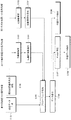
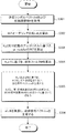
図1は、本発明の第1の実施形態に係るシステム全体の信号処理についてその概要を説明するフローチャートである。はじめに、基地局装置100は、送信データを生成するとともに(ステップS101)、接続している第1の端末装置300および第2の端末装置300に対して、既知の参照信号系列を送信する(ステップS102)。次いで、各端末装置300は受信された既知参照信号系列に基づき、伝搬路推定を行なう(ステップS103)。各端末装置300は推定された伝搬路情報を基地局装置100に通知するが、通知方法については、特定の方法に限定されるものではなく、基地局装置100が伝搬路情報を把握できるのであればどのような方法でも構わない(ステップS104)。例えば、推定された伝搬路情報を有限ビット長に量子化した情報を通知すれば良い。また、基地局装置100と端末装置300間で予め複数の線形フィルタが記載されたコードブックを共有しておき、伝搬路情報と最も相関が高い線形フィルタのインデックスを通知しても良い。
FIG. 1 is a flowchart for explaining an overview of signal processing of the entire system according to the first embodiment of the present invention. First, the
基地局装置100は、各端末装置300より伝搬路情報を取得し、その情報に基づき、各端末装置300宛の送信データに対して、後で述べる送信符号化(プリコーディング)を施す(ステップS105)。プリコーディング後のデータを同一無線リソースに空間多重して、接続されている複数の端末装置300宛に送信する(ステップS106)。複数端末装置300宛のデータが空間多重された信号を受信した端末装置300では、それぞれ前述の伝搬路情報等に基づき、自局の所望データを検出するが(ステップS108)、第1の端末装置300では、modulo演算を含む非線形演算処理を行なう必要があるのに対して(ステップS107)、第2の端末装置300ではmodulo演算は必要としない。
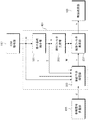
[2.1 基地局装置100]
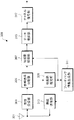
図2は、本発明の第1の実施形態に係る基地局装置100の構成を示すブロック図である。図2に示すように、基地局装置100は、チャネル符号化部101と、データ変調部103と、参照信号多重部105と、Precoding部(プリコーディング部)401と、無線送信部111と、無線受信部113と、制御情報取得部115と、CSI取得部(取得部)117と、送信アンテナ109とを含んで構成されている。
[2.1 Base station apparatus 100]
FIG. 2 is a block diagram showing a configuration of
各端末装置300宛の送信データ系列はチャネル符号化部101において、チャネル符号化が行なわれたのち、データ変調部103において、QPSK、16QAM等にデータ変調される。データ変調部103からの出力は参照信号多重部105に入力され、各端末装置300において伝搬路推定を行なうための既知参照信号系列が参照信号多重部105において多重される。各端末装置300宛の参照信号については、受信した端末装置300において分離可能なように、それぞれが直交するように多重されるものとする。以下の説明では、参照信号は任意の無線リソースに理想的に配置されたものとし、端末装置300では上記既知参照信号系列により、理想的に伝搬路推定が行なわれるものとする。参照信号多重部105の出力は、Precoding部401に入力される。なお、各端末装置300より通知される伝搬路情報についても、CSI取得部117よりPrecoding部401に入力されることとなる。
The transmission data series addressed to each
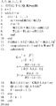
図3は、本発明の第1の実施形態に係るPrecoding部401の装置構成を示すブロック図である。図3に示すように、Precoding部401は、線形フィルタ生成部203と、格子基底縮小部501と、事前干渉抑圧部と、線形フィルタ乗算部207とを含んで構成されている。Precoding部401で行なわれる信号処理は、図17に示したPrecoding部401で行なわれる信号処理とほぼ同じであるが、格子基底縮小部501および事前干渉抑圧部503に行なわれる信号処理が異なっている。はじめに、格子基底縮小部501で行なわれる信号処理について説明する。格子基底縮小部501では入力された伝搬路行列Hに基づいて、Hの直交性を高めるunimodular行列Tが算出される。格子基底縮小技術に適したTの算出アルゴリズムとして、LLLアルゴリズムが良く知られている。
FIG. 3 is a block diagram showing a device configuration of the
図4は、LLLアルゴリズムのアルゴリズムを示す表である。算出されたTに基づいて、事前干渉抑圧部503および線形フィルタ生成部203における信号処理が行なわれる。なお、unimodular行列Tの構成要素はガウス整数であることが望ましいが、伝送特性の劣化を許容できる場合、実数に属する数字が構成要素となっても構わない。しかし、従来のLLLアルゴリズムにおいて算出されるunimodular行列Tでは、空間多重される全端末装置300がmodulo演算を行なえる第1の端末装置300である必要がある。そこで、本実施形態においては、従来のLLLアルゴリズムを改良することで、第2の端末装置300の空間多重を可能とする。
FIG. 4 is a table showing an algorithm of the LLL algorithm. Based on the calculated T, signal processing in the prior
LRA THPにて送信された信号を、端末装置300-iがmodulo演算を行なわずに復調するためには、式(6)においてz^t,i=0である必要がある。z^t,iはベクトル(T−1zt)の第i成分であるから、行列T−1の第i行とztとの積で表現される。ここで、第k成分が1であり、他の構成要素が全て0であるような要素数Uの行ベクトルを第k単位行ベクトルeU,kと定義する。ここで、行列の持つ性質により、U行U列の行列Tの第k行がeU,iであるとき、行列Tの逆行列T−1は第i行にeU,kを有する行列となる。このとき、zt,k=0とすれば、端末装置300-iではmodulo演算を必要としない伝送とできる。つまり、端末装置300-iでmodulo演算を必要としない伝送を実現するためには、行列Tのいずれかの行に第i単位行ベクトルeU,iが存在すれば良いことになる。 In order for the terminal device 300-i to demodulate the signal transmitted by LRA THP without performing the modulo operation, it is necessary that z ^ t, i = 0 in the equation (6). z ^ t, i is represented by the product of the i-th row and z t of because it is the i-th component of the vector (T -1 z t), the matrix T -1. Here, a row vector having the number of elements U in which the k-th component is 1 and all other components are 0 is defined as a k-th unit row vector e U, k . Here, due to the property of the matrix, when the k-th row of the matrix T of U rows and U columns is e U, i , the inverse matrix T −1 of the matrix T is a matrix having e U, k in the i-th row. Become. At this time, if z t, k = 0, the terminal device 300-i can perform transmission that does not require a modulo operation. That is, the i-th unit row vector e U, i only needs to be present in any row of the matrix T in order to realize transmission that does not require a modulo operation in the terminal device 300-i.
LLLアルゴリズムは入力された行列Hに対して、unimodular行列Tを算出しG=HTという直交性の高い行列を算出する。このアルゴリズムをLRA-THPに用いる場合、入力される値は伝搬路行列Hのエルミート転置行列HHであり、このとき算出されるunimodular行列をTHと考えると、行列GH=HHTHが算出され、直交性の高い行列GはG=THとして出力される。なお、入力される値は伝搬路行列Hの転置行列HT、もしくは逆行列H−1のいずれかでも良い。実際のLLLアルゴリズムで出力されるのはTHである一方で、本実施形態の目的はTのいずれかの行にeU,iを存在させることにある。よって、LLLアルゴリズムで算出される行列TH(図4におけるT)のいずれかの列ベクトルがeU,i Hであれば良い。 The LLL algorithm calculates a unimodal matrix T for the input matrix H and calculates a highly orthogonal matrix G = HT. When this algorithm is used for LRA-THP, the input value is the Hermitian transpose matrix H H of the propagation path matrix H. If the unimodular matrix calculated at this time is considered T H , the matrix G H = H H T H And a highly orthogonal matrix G is output as G = TH. The input value may be either the transposed matrix H T of the propagation path matrix H or the inverse matrix H −1 . While the actual LLL algorithm outputs TH, the purpose of this embodiment is to make e U, i exist in any row of T. Therefore, any column vector of the matrix T H (T in FIG. 4) calculated by the LLL algorithm may be e U, i H.
LLLアルゴリズムは、図4から分かるように、4行目から10行目までの(1)準直交化処理、11行目の(2)条件比較、12行目から16行目までの(3)入れ替え作業の3つの処理の繰り返しで構成されている。ここで、unimodular行列Tが直接算出されているのは、(1)の準直交化処理の部分である。unimodular行列の初期値は単位行列Iであるから、第i列を対象とした準直交化処理を行なわなければ、最終的に算出されるTにはeU,i Hが存在することになる。なお、(2)の条件比較および(3)の入れ替え作業により、第i列が違う列(例えば第j列)と交換される場合がある。この場合、新しく第j列がeU,i Hとなる。つまり、繰り返し処理の中で、元々第i列成分であった列ベクトルがどの列に移動したのかを常に把握しておく必要がある。以下の説明では、アルゴリズムが終了した時点でeU,i Hは第v列に存在するものとする。 As can be seen from FIG. 4, the LLL algorithm includes (1) quasi-orthogonalization processing from the 4th row to the 10th row, (2) condition comparison from the 11th row, and (3) from the 12th row to the 16th row. It consists of repetition of three processes of replacement work. Here, the unimodular matrix T is directly calculated in the part of the quasi-orthogonalization process (1). Since the initial value of the unimodular matrix is the unit matrix I, e U and i H exist in the finally calculated T unless the quasi-orthogonalization process for the i-th column is performed. Note that the i-th column may be replaced with a different column (for example, the j-th column) by the condition comparison in (2) and the replacement operation in (3). In this case, the new j-th column becomes e U, i H. In other words, it is necessary to always know to which column the column vector that was originally the i-th column component has moved during the iterative process. In the following description, it is assumed that e U and i H exist in the v-th column when the algorithm is finished.
図5は、本発明の第1の実施形態に係るLLLアルゴリズムのアルゴリズムを示す表である。入力は伝搬路行列Hに加えて、第2の端末装置300の端末装置番号を示すiであり、出力は、unimodular行列Tと最終的にeU,i Hが存在する列番号を示すvである。なお、第2の端末装置300数が複数で有る場合は準直交化を行なわない列が複数となることになる。その場合、(3)の入れ替え処理時に覚えておくべき列番号も複数となる。本実施形態では、格子基底縮小部501からは、図5で表されるアルゴリズムにより、unimodular行列Tとvという二つの情報が出力される。
FIG. 5 is a table showing an algorithm of the LLL algorithm according to the first embodiment of the present invention. The input is i indicating the terminal device number of the second
図3に戻り、線形フィルタ生成部203にはunimodular行列Tと伝搬路行列Hが入力され、線形フィルタWが生成される。線形フィルタWは、格子基底縮小された伝搬路行列Gに対して、GWが単位下三角行列となるような線形フィルタである。Gはユニタリ行列Qと下三角行列Lを用いて、G=LQのようにLQ分解することができるから、GWを単位下三角行列とする線形フィルタWはW=QH{diag(L)}−1となる。生成された線形フィルタは事前干渉抑圧部503および線形フィルタ乗算部207に入力される。
Returning to FIG. 3, the unimodular matrix T and the propagation path matrix H are input to the linear
事前干渉抑圧部503には、送信信号ベクトルd、伝搬路情報H、unimodular行列T、eU,i Hが存在する列番号を示すv、および線形フィルタWが入力され、事前干渉抑圧部503出力としてxが出力されることとなる。xの算出方法は基本技術で述べたように、式(4)を実現するものとなるが、このとき、d^vに対してはmodulo演算を行なわない。つまり、式(4)において、zt=[zt,1,…,zt,v−1,0,zt,v+1,…,zt,Nt]Tとなることになる。具体的には、d^vに対する干渉抑圧は式(3-1)に基づき、それ以外の送信シンボルに対しては式(3-3)に基づいて行なわれることになる。第2の端末装置300が複数である場合、vに該当する数字も複数となるが、この場合も、vに該当する全ての摂動ベクトルを0とすれば良い。
The prior
事前干渉抑圧部503より出力されるxはその後、線形フィルタ乗算部207に入力され、線形フィルタWおよび電力正規化係数βが乗算され、送信信号ベクトルsが出力され、これがPrecoding部401出力となる。
The x output from the prior
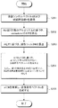
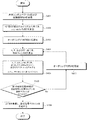
図6は、本発明の第1の実施形態に係るPrecoding部401における信号処理を示すフローチャートである。まず、Precoding部401は、送信シンボルベクトルdおよび伝搬路情報Hを取得する(ステップS201)。次に、格子基底縮小部501では入力された伝搬路行列Hに基づいて、Hの直交性を高めるunimodular行列Tが算出される(ステップS202)。伝搬路情報Hと格子基底縮小部501から出力されたTは線形フィルタ生成部203に入力され、線形フィルタWが生成される(ステップS203)。続いて、Precoding部401に入力された送信シンボルベクトルdは事前干渉抑圧部503に入力されることで、各端末装置300で観測される干渉成分が、予め減算される(ステップS204)。この時、第1の端末装置300宛てには式(3-3)に基づいて行なわれ、第2の端末装置300宛てには式(3-1)に基づいて行なわれる。次に、線形フィルタ乗算部207では、入力されたxに対して、線形フィルタWが乗算され、送信信号ベクトルsが算出される(ステップS205)。
FIG. 6 is a flowchart showing signal processing in the
図2に戻り、基地局装置100では、Precoding部401の出力sが対応する各送信アンテナ109の無線送信部111に入力される。無線送信部111において、ベースバンド帯の送信信号が無線周波数(RF)帯の送信信号に変換される。無線送信部111の出力信号は、各送信アンテナ109よりそれぞれ送信される。
Returning to FIG. 2, in the
[2.2 端末装置300]
図7は、本発明の第1の実施形態に係る第1の端末装置300の構成を示すブロック図である。図8は、本発明の第1の実施形態に係る第2の端末装置300の構成を示すブロック図である。図7および図8に示すように、端末装置300はアンテナ301と、無線受信部303と、参照信号分離部305と、伝搬路推定部309と、フィードバック情報生成部311と、無線送信部313と、伝搬路補償部601と、データ復調部315と、チャネル復号部317とを含んで構成されている。本実施形態においては、端末装置300-iが第2の端末装置300に含まれ、残りの端末装置300については全て第1の端末装置300に含まれるものとする。第1の端末装置300と第2の端末装置300の装置構成は同じであるが、それぞれの伝搬路補償部601において行なわれる信号処理が異なる。
[2.2 Terminal device 300]
FIG. 7 is a block diagram showing the configuration of the first
各端末装置300においては、アンテナ301で受信された信号が、無線受信部303に入力され、無線受信部303において、ベースバンド帯の信号に変換される。ベースバンド帯に変換された信号は、参照信号分離部305に入力される。参照信号分離部305では、受信信号はデータ系列と既知参照信号系列とに分離され、データ系列は伝搬路補償部601に入力され、既知参照信号系列は伝搬路推定部309に入力される。伝搬路推定部309では、入力された既知参照信号系列を用いて伝搬路推定が行なわれる。各端末装置300宛の既知参照信号系列はそれぞれ直交するように基地局装置100より送信されているから、端末装置300では、伝搬路情報を推定することができる。端末装置300-uにおいて推定される伝搬路情報は基地局装置100のPrecoding部401にて用いられる伝搬路行列Hの第u行成分に該当する。推定された伝搬路情報はそれぞれ伝搬路補償部601およびフィードバック情報生成部311に入力される。
In each
フィードバック情報生成部311では、各端末装置300がフィードバックする伝搬路情報形式に応じて、基地局装置100にフィードバックする情報を生成する。本発明においては、伝搬路情報形式については何かに限定されるものではない。例えば、推定された伝搬路情報を有限ビット長に量子化した情報を通知すれば良い。また、基地局装置100と端末装置300間で予め複数の線形フィルタが記載されたコードブックを共有しておき、伝搬路情報と最も相関が高い線形フィルタのインデックスを通知しても良い。フィードバック情報生成部311で生成された情報は、無線送信部313に入力され、基地局装置100に向けて通知される。
The feedback
基地局装置100ではCSI取得部117において、通知されてきた情報と、その伝搬路情報形式に基づいて、伝搬路情報Hを取得し、取得された伝搬路情報がPrecoding部401に入力されることになる。一方、受信データ系列については伝搬路補償部601に入力され、伝搬路補償が行なわれる。ベースバンド帯に変換された受信信号は式(6)で与えられるものと同じ形式である。
In
端末装置300-uの伝搬路補償部601では、入力された受信信号から電力正規化項βを除算する。そのため、端末装置300はβの値を把握する必要があるが、βは基地局装置100より送信される既知参照信号より推定することが可能である。例えば、基地局装置100が伝搬路情報推定のために送信する既知参照信号の一部に対して、受信データ系列と同様のPrecoding処理を行なうことで、βを推定できる。以下では、βは理想的に推定できるものとして説明していく。なお、端末装置300から基地局装置100への伝搬路情報のフィードバック精度が低い場合や、伝搬路の時間および周波数の選択性が激しい場合、端末装置300−uの受信信号において、希望信号duの振幅および位相が変動する。この振幅および位相の変動は電力正規化項βと同様に推定可能であるから、βを除算する際に、同時に振幅および位相の変動分の補償を行えば良い。電力正規化項が除算されたのち、基地局装置100のPrecoding部401で用いられたmodulo演算と同じmodulo幅を有するmodulo演算が適用される。しかし、本実施形態の基地局装置100のPrecoding部401において算出されるunimodulor行列Tと、modulo演算の適用方法により、z^tのうち、端末装置300-iに該当する成分、つまり、z^t,iについては0となる。
The propagation
そのため、第2の端末装置300に含まれる端末装置300-iの伝搬路補償部701においてはmodulo演算を必要とせず、電力正規化係数βの除算のみが行なわれる。一方で、第1の端末装置300に含まれる端末装置300については、基本技術と同様に、電力正規化係数βの除算後にmodulo演算が行なわれる事となる。その後、伝搬路補償部601、701の出力はデータ復調部315およびチャネル復号部317に入力され、データ復調、チャネル復号がそれぞれ適用されたのち、各端末装置300の送信データが検出される。以上の処理により、LRA-THP MU-MIMOにおいても、第1の端末装置300と第2の端末装置300とを高効率に空間多重させることが可能となる。
Therefore, the propagation
ところで、本実施形態によるMU-MIMOでは、第1の端末装置300と第2の端末装置300とを空間多重させているが、このことは、modulo演算を行なう端末装置300と行なわない端末装置300とを空間多重できることを意味している。modulo演算はIUIの増加に伴う送信電力の増大を抑圧するため、伝送特性の改善に寄与できる。しかし、IUIが小さい場合には、modulo演算に起因するmodulo損失やprecoding損失により伝送特性がmodulo演算を行なわない場合より劣化する場合があり、特にQPSK変調時に劣化しやすい。そのために、空間多重されている端末装置300が全て第1の端末装置300であった場合でも、IUIの状況に応じて、modulo演算の適用の有無を適応的に切り替える伝送方法が取られる場合がある。このときに、観測されるIUIが少ない端末を第2の端末装置300と見なすことにより、modulo演算を行なわないQPSK変調信号と、modulo演算を行なうQPSK変調信号とを本実施形態の方法により空間多重させることが可能となる。
By the way, in the MU-MIMO according to the present embodiment, the first
modulo演算の切り替えは、実際のプリコーディング時に測定できる干渉成分(例えば式(3-1)の第2項)の電力を測定し、ある閾値を超えたらmodulo演算を行ない、超えなければmodulo演算を行なわないように制御すれば良い。閾値については、与えられた符号化率等に基づき、予めBER測定などを行ない決定すれば良い。なお、このとき端末装置300は受信された信号に対して、modulo演算の有無を知る必要がある。基地局装置100が端末装置300に対して、新たに制御信号により通知しても良いが、基地局装置100と端末装置300とが共有するMCSに関連付けて通知する方法が考えられる。例えば、QPSK変調であれば、常にmodulo演算を行なうように制御しても良いし、modulo演算を行なうQPSKと行なわないQPSKをそれぞれMCSの項目に含めるようなシステムとしても良い。
To switch the modulo calculation, measure the power of the interference component that can be measured during actual precoding (for example, the second term in equation (3-1)), perform the modulo calculation if it exceeds a certain threshold, and if not exceed the modulo calculation Control may be performed so that it is not performed. The threshold value may be determined by performing BER measurement or the like in advance based on a given coding rate or the like. At this time, the
本実施形態においては、伝送方式(もしくはアクセス方式)については制限を与えていない。例えば、LTEの下りリンク伝送に採用されている直交周波数分割多重アクセス(OFDMA)方式に適用することが可能である。この場合は、サブキャリア毎に本実施形態を適用すれば良く、また複数サブキャリアを一纏めとしたリソースブロック毎に本実施形態を適用しても良い。同様に、シングルキャリアベースのアクセス方式(例えばシングルキャリア周波数分割多重アクセス(SC-FDMA)方式など)に適用することも可能であり、周波数成分毎に適用しても良いし、送信電力の強調を回避するために、全周波数帯域に渡って同一のプリコーディングを行なうようにしても良い。 In the present embodiment, no restriction is imposed on the transmission method (or access method). For example, the present invention can be applied to an orthogonal frequency division multiple access (OFDMA) system that is employed in LTE downlink transmission. In this case, the present embodiment may be applied to each subcarrier, and the present embodiment may be applied to each resource block in which a plurality of subcarriers are grouped. Similarly, it can be applied to a single carrier-based access method (for example, a single carrier frequency division multiple access (SC-FDMA) method, etc.), and may be applied to each frequency component, and the transmission power is emphasized. In order to avoid this, the same precoding may be performed over the entire frequency band.
第1の実施形態によれば、第1の端末装置300と、第2の端末装置300とが混在している無線通信システムにおいて、LRA-THPによる高効率な空間多重が可能となるため、システム全体の周波数利用効率の改善に寄与できる。
According to the first embodiment, in a wireless communication system in which the first
[3.第2の実施形態]
第1の実施形態においては、格子基底縮小部501で算出されるunimodular行列Tと、事前干渉抑圧部における信号処理を従来技術と異なるものとすることで、第1の端末装置300と第2の端末装置300とをLRA-THPにより空間多重させる方法を明らかにした。しかし、第1の実施形態の方法では、LLLアルゴリズムの収束速度が、従来の方法と比較して、著しく劣化してしまう場合がある。そこで、第2の実施形態では、格子基底縮小部に入力される伝搬路行列に予めオーダリングを施すことにより、第1の端末装置300と第2の端末装置300とをLRA-THPにより空間多重させながら、LLLアルゴリズムの収束性の低下を回避する方法を対象とする。
[3. Second Embodiment]
In the first embodiment, the unimodular matrix T calculated by the lattice
第1の実施形態と同様に、Nt本の送信アンテナ109を有する基地局装置100(送信装置とも呼ぶ)に対して、1本のアンテナ301を有する端末装置300(受信装置とも呼ぶ)がU個接続している通信を対象とし、端末装置300のうち、端末装置300-iが第2の端末装置300であるものとする。なお、各端末装置300が有するアンテナ301数や、端末装置300に含まれる第1の端末装置300と第2の端末装置300の割合については、これに限ったものではなく、複数アンテナ301を有する端末装置300が存在したり、複数の第2の端末装置300が存在する場合にも、本発明は適用可能である。
Similar to the first embodiment, a base station apparatus 100 (also referred to as a transmission apparatus) having N t transmission antennas 109 is connected to a terminal apparatus 300 (also referred to as a reception apparatus) having one
[3.1 基地局装置100]
第2の実施形態に係る基地局装置100構成は図2とほぼ同じであり、異なるのはPrecoding部における信号処理のみであるため、以下では、第2の実施形態に係るPrecoding部について説明する。
[3.1 Base station apparatus 100]
The configuration of the
図9は、本発明の第2の実施形態に係るPrecoding部801の構成を示すブロック図である。図9に示すように、Precoding部801は、線形フィルタ生成部203と、格子基底縮小部803と、事前干渉抑圧部805と、線形フィルタ乗算部207に加えて、オーダリング部807とを含んで構成されている。Precoding部801では、入力される伝搬路行列Hが初めにオーダリング部807に入力されてオーダリング処理が施される。ここでいうオーダリングとは、行列の列同士(もしくは行同士)を入れ替えることを意味する。オーダリング済みの伝搬路行列をHpとすると、Hpは順列行列Πと伝搬路行列Hを用いて、Hp=ΠHと表現できる。
FIG. 9 is a block diagram showing the configuration of the
本実施形態においては、第2の端末装置300に該当する伝搬路情報が、オーダリング済み伝搬路行列Hpの一番上になるように制御する。例えば、本実施形態が対象としているように、端末装置300-iが第2の端末装置300であった場合、順列行列Πとして、eU,iが第1行に配置されるような行列を用いれば良い。Πの他の行については、自由に入れ替えて良いから、順列行列としては全部で(U−1)!通りの選択肢が考えられることとなる。いずれを用いても本実施形態の目的は達せられるが、一般にLLLアルゴリズムでは、入力行列の列ベクトルの大きさは、左から昇順に並ぶ方がアルゴリズムの収束特性を向上させる面から望ましい。そのような順列行列を求める方法として、例えば、初めに伝搬路行列Hに対して、列ベクトルの大きさが左から昇順になるようなソート付きQR分解を行なうことで、ある順列行列Πを生成する。その後、Πの各行成分のうちeU,iを有する行を一番上に配置しなおせば良い。
In the present embodiment, the channel information corresponding to the second
オーダリング部807出力として、オーダリング済みの伝搬路行列Hpと選択されたオーダリング行列Πがそれぞれ出力される。オーダリング部807出力Hpは次いで、格子基底縮小部803に入力され、格子基底縮小処理が施されることになる。
As the output of the
図10は、本発明の第2の実施形態に係る格子基底縮小部803において用いられるアルゴリズムを示す表である。図10と第1の実施形態で対象とした図5の違いは、第2の端末装置300に係る伝搬路行列成分(本実施形態では、第2の端末装置300は端末装置300-iであるから、入力行列Hの第i列成分が該当する)に対する信号処理である。第1の実施形態では、第i列成分に対して、準直交化処理こそ行なわないものの、(2)条件比較、および(3)入れ替え作業については適用している。この処理により、端末装置300-iを考慮した格子基底縮小が行なえるため、たとえ第2の端末装置300が混在したとしても、良好な伝送特性を実現できる。しかし、LLLアルゴリズムは行列の全成分に対して、(1)〜(3)の信号処理を行なうことを前提としているため、図5の方法では、特に第2の端末装置300数が複数である場合に、アルゴリズムの収束に膨大な時間を要してしまう。
FIG. 10 is a table showing an algorithm used in the lattice
そこで、第2の実施形態が用いるアルゴリズムは、図10に示されているように、入力された行列に対して、所定の列番号vより信号処理を開始し、vより小さい列番号の列ベクトルについては、一切の信号処理を行なわないものとしている。これは、事前のオーダリングにより、第2の端末装置300に関わる伝搬路行列成分が第1行(アルゴリズムに入力されるのはHHであるから、アルゴリズム中では第1列を指す)に置換されているためである。この場合、アルゴリズムの収束性は図4で示されている従来のLLLアルゴリズムとほぼ同等とすることができる。本実施形態の場合、第2の端末装置300数は1個であるから、vとして3が入力されることになる。つまり、vには従来のLLLアルゴリズムのkの初期値である2に第2の端末装置300数が加算されたものとなる。格子基底縮小部803からは最終的にunimodular行列Tが出力される。
Therefore, as shown in FIG. 10, the algorithm used in the second embodiment starts signal processing for an input matrix from a predetermined column number v, and a column vector having a column number smaller than v. Is not subjected to any signal processing. This is because the propagation path matrix component related to the second
次いで、線形フィルタ生成部203において、オーダリング部807出力Hpと格子基底縮小部803出力Tに基づいて、線形フィルタWが生成される。生成される線形フィルタWは第1の実施形態と同様に、格子基底縮小された伝搬路行列G=THp=TΠHを単位下三角行列に変換するものであるから、Gに対するLQ分解により得られる下三角行列Lとユニタリ行列QからW=QH{diag(L)}−1と算出できる。線形フィルタ生成部203出力Wは、事前干渉抑圧部805に入力される。事前干渉抑圧部805には、他にオーダリング部807出力Πと格子基底縮小部803出力Tとオーダリング済みの伝搬路行列Hpおよび、送信シンボルベクトルdが入力され、事前干渉抑圧が行なわれる。実際の信号処理は第1の実施形態とほぼ同様であり、式(4)のような送信信号ベクトルxを作り出すものであるが、若干処理が異なる。
Then, the
まず、第1の実施形態では、dにTを乗算したTdを新たな送信シンボルベクトルd^として干渉抑圧を行なっていたが、第2の実施形態においては、d^=TΠdを新たな送信シンボルベクトルとして干渉抑圧を行なう。そして、第1の実施形態においては、modulo演算の有無を、unimodular行列が有する単位行ベクトルの位置に応じて決定していたのに対して、第2の実施形態においては、d^のうち、第1成分から、第2の端末装置300数だけの成分までについてはmodulo演算を行なわないように制御する。例えば、本実施形態では第2の端末装置300数は1であるから、d^のうち、d^1に対してのみ、modulo演算を行なわない、つまり式(3-1)に基づいて干渉抑圧を行なうことになる。第2の端末装置300数がmであれば、d^1〜d^mに対してmodulo演算を行なわないということである。それ以外の送信シンボルについては式(3-3)に基づいて干渉抑圧が行なわれる。以上の処理により、最終的に事前干渉抑圧部805より出力される送信符号ベクトルxは式(8)で与えられる。
図11は、本発明の第2の実施形態に係るPrecoding部801の信号処理を示すフローチャートである。まず、Precoding部801は、送信シンボルベクトルdおよび伝搬路情報Hを取得する(ステップS301)。次に、入力される伝搬路行列Hが初めにオーダリング部807に入力されてオーダリング処理が施される(ステップS302)。次に、格子基底縮小部803では入力された伝搬路行列Hpと図10記載のアルゴリズムに基づいて、Hpの直交性を高めるunimodular行列Tが算出される(ステップS303)。伝搬路情報Hpと格子基底縮小部501から出力されたTは線形フィルタ生成部203に入力され、線形フィルタWが生成される(ステップS304)。続いて、Precoding部801に入力された送信シンボルベクトルdは事前干渉抑圧部805に入力されることで、各端末装置300で観測される干渉成分が、予め減算される(ステップS305)。この時、第1の端末装置300宛てには式(3-3)に基づいて行なわれ、第2の端末装置300宛てには式(3-1)に基づいて行なわれる。次に、線形フィルタ乗算部207では、入力されたxに対して、線形フィルタWが乗算され、送信信号ベクトルsが算出される(ステップS306)。以降の信号処理については、Precoding部801出力に対する基地局装置100の信号処理を含めて図2と同じであるため、説明は省略する。
FIG. 11 is a flowchart showing signal processing of the
[3.2 端末装置300]
第2の実施形態に係る端末装置300構成は、第1の端末装置300および第2の端末装置300ともに、それぞれ図7および図8と同じであり、行なわれる信号処理も同じであるから説明は省略する。
[3.2 Terminal apparatus 300]
The configuration of the
第2の実施形態では、格子基底縮小部803において行なわれる格子基底縮小アルゴリズムを変更することで、格子基底縮小アルゴリズムの収束速度を低下させない方法を対象とした。本実施形態の方法によれば、伝搬路の直交性は若干低下するものの、特に第2の端末装置300数が多い場合に、格子基底縮小アルゴリズムを第1の実施形態の方法と比較して、高速に収束させることが可能である。
The second embodiment targets a method that does not decrease the convergence speed of the lattice basis reduction algorithm by changing the lattice basis reduction algorithm performed in the lattice
[4.第3の実施形態]
これまで説明してきた方法はいずれも、格子基底縮小部803で算出されるunimodular行列Tを従来LRA-THPで用いられてきたTとは異なるものを使うことにより、第1の端末装置300と第2の端末装置300とを空間多重することを可能としてきた。しかし、Tの生成に制限を加えることは、伝搬路の直交性や、格子基底縮小アルゴリズムの収束速度を著しく低下させてしまう場合がある。ところで、LRA-THPは伝搬路に対する準直交化処理と、THPによる事前干渉抑圧処理の二つの信号処理を組み合わせたものと捉える事ができ、これまでの方法は、準直交化処理の方を主に変更することで、空間多重を実現させてきたと言える。第3の実施形態では、THPによる事前干渉抑圧処理を変更することにより、空間多重を実現させる方法を対象とする。
[4. Third Embodiment]
In any of the methods described so far, the unimodular matrix T calculated by the lattice
第1の実施形態と同様に、Nt本の送信アンテナ109を有する基地局装置100(送信装置とも呼ぶ)に対して、1本のアンテナ301を有する端末装置300(受信装置とも呼ぶ)がU個接続している通信を対象とし、端末装置300のうち、端末装置300-iが第2の端末装置300であるものとする。なお、各端末装置300が有するアンテナ301数や、端末装置300に含まれる第1の端末装置300と第2の端末装置300の割合については、これに限ったものではなく、複数アンテナ301を有する端末装置300が存在したり、複数の第2の端末装置300が存在する場合にも、本発明は適用可能である。
Similar to the first embodiment, a base station apparatus 100 (also referred to as a transmission apparatus) having N t transmission antennas 109 is connected to a terminal apparatus 300 (also referred to as a reception apparatus) having one
[4.1 基地局装置100]
第3の実施形態に係る基地局装置100構成は図2とほぼ同じであり、異なるのはPrecoding部801における信号処理のみであるため、以下では、第3の実施形態に係るPrecoding部について説明する。
[4.1 Base station apparatus 100]
The configuration of the
図12は、本発明の第3の実施形態に係るPrecoding部901の構成を示すブロック図である。装置構成は図9とほぼ同じであるが、第2の実施形態とはオーダリング部903の位置が異なり、また摂動ベクトル制御部905が追加される構成となる。はじめに、入力された伝搬路行列Hが格子基底縮小部907に入力され、格子基底縮小処理が施されることになる。第1および第2の実施形態においては、格子基底縮小部907で算出されるunimoular行列Tに制限を与えていたが、本実施形態においては、算出されるTはunimodular行列でありさえすればなんでも良い。例えば、図4のLLLアルゴリズムをそのまま適用し、unimoular行列Tを算出すれば良い。算出された行列Tはその後線形フィルタ生成部909と事前干渉抑圧部911に入力される。
FIG. 12 is a block diagram showing the configuration of the
次いで、線形フィルタ生成部909には、格子基底縮小部907出力Tと伝搬路行列Hおよびオーダリング部903出力Πが入力される。オーダリング部903における信号処理については後述するが、初めはΠとして単位行列Iが入力されることになる。線形フィルタ生成部909では、入力された情報に基づき見掛け上の伝搬路行列G=ΠTHを生成する。第2の実施形態とは、unimodular行列Tと順列行列Πを乗算する順番が異なる。生成される線形フィルタWは伝搬路行列Gに対して、GWを単位下三角行列とするものであるから、第2の実施形態と同様に、Gに対するLQ分解により得られる下三角行列Lとユニタリ行列QからW=QH{diag(L)}−1と算出できる。
Next, the lattice
線形フィルタ生成部909出力Wは、事前干渉抑圧部911に入力される。事前干渉抑圧部911には、他に伝搬路行列Hとオーダリング部903出力Πと格子基底縮小部907出力Tおよび、送信シンボルベクトルdが入力され、事前干渉抑圧が行なわれる。ここで行なわれる事前干渉抑圧は、伝搬路行列がHからGに、見掛け上の送信シンボルベクトルがd^=ΠTdに変更される以外は、基本技術で述べた事前干渉抑圧部911における信号処理と同じであり、式(9)のような送信符号ベクトルxを生成するものである。
ここで、式(9)で表現される送信信号に線形フィルタWを乗算したものを基地局装置100より伝送したとすると、受信信号は式(10)で与えられることになる。
ここで、第2の端末装置300である端末装置300-iにおいて、modulo演算を行なわずとも信号復調をするためには、受信信号を構成する各成分のうち、列ベクトルT−1Π−1ztの第i列成分が0で有りさえすればよい。ここで、摂動ベクトルztは式(3-1)および式(3-2)から分かるように、伝搬路行列に応じて決まる残留IUIの大きさ(式(2-2)中のai,j(i>j)が該当)によって変化するから、伝搬路行列が変化すれば、摂動ベクトルの値も変わる。
Here, in the terminal device 300-i which is the second
そこで、事前干渉抑圧部911出力xは一度、摂動ベクトル制御部905に入力され、第2の端末装置300で観測されるmodulo演算の摂動項T−1Π−1ztが0であるかどうかを測定し、0であれば、摂動ベクトル制御部905入力xをそのまま出力として、線形フィルタ乗算部に出力し、摂動項T−1Π−1ztが0でなければ、入力されたxを破棄し、オーダリング部903に対して、新たな順列行列を生成するよう制御信号を出力する。
Therefore, whether the prior
オーダリング部903における具体的な順列行列の探査方法としては、空間多重数がUである場合、選択可能な順列行列はU!個だけ存在するから、それらすべてに関してT−1Π−1ztを算出し、第2の端末装置300に関わる成分が0となる順列行列を探せば良い。
As a specific permutation matrix search method in the
以上の処理により摂動ベクトル制御部905において適切な送信符号ベクトルxが得られた後、送信符号ベクトルxを線形フィルタ乗算部に入力する。線形フィルタ乗算部では、電力正規化などが行なわれ、Precoding部901出力sが生成される。
After the perturbation
図13は、本発明の第3の実施形態に係るPrecoding部901の信号処理について示すフローチャートである。まず、Precoding部901は、送信シンボルベクトルdおよび伝搬路情報Hを取得する(ステップS401)。次に、格子基底縮小部907では入力された伝搬路行列Hと図4記載のアルゴリズムに基づいて、Hの直交性を高めるunimodular行列Tが算出される(ステップS402)。次に、オーダリング部903により、オーダリング行列Πとして単位行列Iが入力される(ステップS403)。伝搬路情報Hと格子基底縮小部501から出力されたTとオーダリング行列Πは線形フィルタ生成部203に入力され、線形フィルタWが生成される(ステップS404)。続いて、Precoding部901に入力された送信シンボルベクトルdは事前干渉抑圧部911に入力されることで、各端末装置300で観測される干渉成分が、予め減算される(ステップS405)。この時、常に式(3-3)に基づいて行なわれる。
FIG. 13 is a flowchart showing signal processing of the
摂動ベクトル制御部905は、第2の端末装置300で観測される摂動ベクトルが0であるかどうかを判断し(ステップS406)、0でなければ(ステップS406:No)、オーダリング部903に対して、オーダリング行列Πを更新するよう制御信号を出力し(ステップS407)、ステップS404に戻る。0であれば(ステップS406:Yes)、線形フィルタ乗算部207では、入力されたxに対して、線形フィルタWが乗算され、送信信号ベクトルsが算出される(ステップS408)。
The perturbation
ただし、全ての順列行列を探査したとしても、T−1Π−1ztの第2の端末装置300に関わる成分が0となる順列行列が抽出されるとは限らない。この場合、全ての順列行列の中で、該当要素を最も小さくできる順列行列を選択すれば良いが、その場合、第2の端末装置300の伝送特性は残留する摂動ベクトルの大きさに比例して劣化する。しかし、変調方式がQPSK等の位相変調であった場合、付与されている摂動ベクトルが送信データと同じ象限に存在すれば(例えば、QPSK変調時に第2の端末装置300宛の送信信号が、2−1/2(1+j)である場合に、摂動ベクトルが正の整数(p,q)を用いてp+jqと表現できる状態)、データ復調には影響を与えないから、そのような摂動ベクトルとなる順列行列を選択しても良い。同様の事は、16QAMを用いる場合でも、信号候補点の位置によって摂動ベクトルの付与が信号復調に影響しない場合があることを利用できる。
However, even if all the permutation matrices are searched, the permutation matrix in which the component related to the second
また、IUIが小さい場合にQPSK変調はmodulo演算を行なうと伝送特性は劣化してしまうから、空間多重されている端末装置300が全て第1の端末装置300であったとしても、QPSK変調を行なう端末装置300が混在している場合に、QPSK変調を行なう端末装置300宛の信号に付与される摂動ベクトルの存在事象が送信データと一致するような順列行列を選択し、端末装置300側ではmodulo演算を行なわないように制御しても良い。
Further, when modulo operation is performed for QPSK modulation when the IUI is small, transmission characteristics deteriorate. Therefore, even if all the spatially multiplexed
また、適切な順列行列が発見されない場合、各端末装置300宛の送信信号に対する干渉抑圧を行なわない方法も考えられる。つまり、IUIを完全抑圧に行なうためには、式(3-1)で表現される干渉抑圧を行なう必要があるが、一部の干渉を残留させれば、その後式(3-2)で付与される摂動ベクトルも変わることとなる。そこで、順列行列だけではなく、事前干渉抑圧部911における干渉抑圧を変化させることで、目的を達するように制御しても良い。その場合、残留IUIを許容する端末装置300の伝送特性は劣化してしまうことになるから、残留IUIを許容させる端末装置300は、元々受信品質に優れた端末装置300を選択することが望ましい。Precoding部901以外の信号処理については、全て第2の実施形態と同様であるから説明は省略する。
In addition, when an appropriate permutation matrix is not found, a method of not performing interference suppression on a transmission signal addressed to each
[4.2 端末装置300]
第3の実施形態に係る端末装置300構成は、第1の端末装置300および第2の端末装置300ともに、それぞれ図7および図8と同様であり、行なわれる信号処理も第1および第2の実施形態で説明したものと同じであるから説明は省略する。第3の実施形態では、格子基底縮小部907において行なわれる格子基底縮小アルゴリズムを変化させず、事前干渉抑圧部911における信号処理を変更することで、第1の端末装置300と第2の端末装置300とを空間多重させる方法を対象とした。第1や第2の実施形態と異なり、事前干渉抑圧の方法を変更するため、空間多重された端末装置300間で伝送品質が一定とならないという問題はあるものの、格子基底縮小は完全に行なわれるため、伝搬路の直交性を維持しやすく、また収束アルゴリズムの収束速度に影響を与えずに空間多重を行なうことが可能となる。
[4.2 Terminal device 300]
The configuration of the
[5.第4の実施形態]
これまで説明してきた方法はいずれも、格子基底縮小部907で算出されるunimodular行列Tと伝搬路行列Hに基づきTHPを行なうLRA-THPを前提とした方法である。ところで、THPを含む非線形プリコーディングは全てVector perturbation(VP)と呼ばれる技術に帰着することが知られている。VP技術の演算量を削減したものが、THPやLRA-THPであると言える。第4の実施形態では、VPの考え方を応用して、格子基底縮小を用いる非線形MU-MIMOで第1の端末装置300と第2の端末装置300とを空間多重させる方法を対象とする。
[5. Fourth Embodiment]
All of the methods described so far are based on LRA-THP that performs THP based on the unimodal matrix T calculated by the lattice
第1の実施形態と同様に、Nt本の送信アンテナ109を有する基地局装置100(送信装置とも呼ぶ)に対して、1本のアンテナ301を有する端末装置300(受信装置とも呼ぶ)がU個接続している通信を対象とし、端末装置300のうち、端末装置300-iが第2の端末装置300であるものとする。なお、各端末装置300が有するアンテナ301数や、端末装置300に含まれる第1の端末装置300と第2の端末装置300の割合については、これに限ったものではなく、複数アンテナ301を有する端末装置300が存在したり、複数の第2の端末装置300が存在する場合にも、本発明は適用可能である。
Similar to the first embodiment, a base station apparatus 100 (also referred to as a transmission apparatus) having N t transmission antennas 109 is connected to a terminal apparatus 300 (also referred to as a reception apparatus) having one
[5.1 基地局装置100]
第4の実施形態に係る基地局装置100構成は図2とほぼ同じであり、異なるのはPrecoding部における信号処理のみであるため、以下では、第4の実施形態に係るPrecoding部について説明する。Precoding部の説明の前に、VP技術について簡単に説明する。式(4)で与えられるLRA-THPの送信信号において、unimodular行列Tを単位行列Iに置き換えたものが、THP MU-MIMOの送信信号ベクトルとなり、その後線形フィルタが乗算された送信信号sは式(11-1)で与えられる。
![]()
The configuration of the
![]()
ここで、摂動ベクトルztを零ベクトルに置きかえることで、ZF規範に基づく線形MU-MIMOの送信信号に一致する。つまり、THP MU-MIMOは線形MU-MIMOの送信信号に摂動ベクトルを付与することにより送信電力を軽減したものと言える。ここで、THPでは式(3-2)に基づいて、各端末装置300で独立に摂動ベクトルを求めているから各端末装置300の所要送信電力を一定にできる。VPは空間多重され送信される送信信号自体の送信電力を最小とする摂動ベクトルを求める方法であり、その送信信号は式(11-2)のように表現できる。
しかし、候補摂動ベクトルは無数に存在し、空間多重数が増加するにつれて、候補数は指数関数的に増加していくため、VPをそのまま用いるのは非現実的である。ところで、LRA-THPの線形フィルタ乗算後の送信信号は式(11-3)で与えられることになる。
![]()
![]()
基本的には式(11-1)と同様であるが、摂動ベクトルにT−1が乗算された形となる。この場合、ztはTHPにより送信符号毎に独立に求められたものであるが、T−1は与えられた伝搬路行列を直交化させるためのものであり、伝搬路行列全体を考慮して算出された行列であるから、z^t=T−1ztは送信信号全体の送信電力をztよりも大幅に抑圧できる摂動ベクトルとなる。よって、この摂動ベクトルを基にVPの摂動ベクトルを探査することで、演算量の大幅な削減が行なえることが知られている。本実施形態では、この考えに基づき、第1の端末装置300と第2の端末装置300とを空間多重させるプリコーディングを行なう。
Basically, this is the same as the equation (11-1), but the perturbation vector is multiplied by T- 1 . In this case, z t is obtained independently for each transmission code by THP, but T −1 is for orthogonalizing a given propagation path matrix, considering the entire propagation path matrix. since the calculated a matrix, z ^ t = T -1 z t is the perturbation vector can be suppressed to a greater extent than the transmit power z t of the entire transmission signal. Therefore, it is known that the amount of calculation can be significantly reduced by searching for a perturbation vector of VP based on this perturbation vector. In the present embodiment, based on this idea, precoding for spatially multiplexing the first
図14は、本発明の第4の実施形態に係るPrecoding部1001の構成を示すブロック図である。図14に示すように、Precoding部1001は、線形フィルタ生成部1003と、格子基底縮小部1005と、摂動ベクトル制御部1007とを含んで構成されている。はじめに、格子基底縮小部1005に伝搬路行列Hが入力され、格子基底縮小が行なわれる。実際の信号処理は基本技術で述べた方法と同じであり、例えば、図4に示したLLLアルゴリズムに基づいてunimodular行列Tを求めれば良い。格子基底縮小部1005より出力された行列Tは線形フィルタ生成部1003に入力される。線形フィルタ生成部1003には格子基底縮小部1005出力Tと伝搬路行列Hが入力されて、線形フィルタが生成される。線形フィルタ生成部1003において生成される線形フィルタWは格子基底縮小された伝搬路行列G=THを対角行列にするフィルタであり、例えば、Gの逆行列G−1を用いれば良い。また、MMSE規範に基づく線形フィルタを用いても良い。生成された線形フィルタWは摂動ベクトル制御部1007に入力されることになる。
FIG. 14 is a block diagram showing a configuration of a
摂動ベクトル制御部1007には、送信シンボルベクトルdと線形フィルタWおよびunimodular行列Tが入力され、摂動ベクトルが算出される。本実施形態では、摂動ベクトルとして、第2の端末装置300に属する端末装置300-iにおいて、modulo演算を必要としないような摂動ベクトルを探査する。LRA-THPにおいて、THPによる事前干渉抑圧を行なわなかった場合の送信信号もやはり式(11-3)のように表現することができる。摂動ベクトル制御部1007では、はじめに式(11-3)で表現される信号を算出する。このとき、摂動ベクトルz^t=T−1ztを第1の摂動ベクトルと呼ぶこととする。しかし、第2の端末装置300に属する端末装置300-i宛の送信符号xiには、z^t,iが付与される事となり、このままでは端末装置300-iではmodulo演算を行なわないと信号復調することが出来ない。そこで、摂動ベクトル制御部1007では、z^tに加えて、新たな摂動ベクトルzTを付与する。zTを第2の摂動ベクトルと呼ぶ。つまり、最終的な送信信号を式(11-4)のようにすることを意味する。
![]()
![]()
このとき、新たに付与する摂動ベクトルzTの第i成分zT,iについては、zT,i+z^t,i=0を満たすように制御する。このように摂動ベクトルを新たに付与することにより、端末装置300-iではmodulo演算を用いずとも信号復調することができる。zT,i以外の摂動ベクトルについては、特に制限は存在しないが、適切な摂動ベクトルを選択しないと、伝送特性は大幅に劣化してしまう。伝送特性を劣化させないためには、zT,i以外の摂動ベクトルについては、送信信号電力を最小にするように選択する必要がある。つまり、求めるべき摂動ベクトルzTは式(12)を満たすものとなる。
以上の信号処理により、摂動ベクトルzTを算出したのち、電力正規化係数βを算出する。摂動ベクトル制御部1007からは電力正規化係数βが乗算された送信信号ベクトルsが出力され、Precoding部1001出力として出力される。このとき、sは式(13)で与えられる。
図15は、本発明の第4の実施形態に係るPrecoding部1001の信号処理について示すフローチャートである。まず、Precoding部1001は、送信シンボルベクトルdおよび伝搬路情報Hを取得する(ステップS501)。次に、格子基底縮小部1005では入力された伝搬路行列Hと図4記載のアルゴリズムに基づいて、Hの直交性を高めるunimodular行列Tが算出される(ステップS502)。伝搬路情報Hと格子基底縮小部1005から出力されたTは線形フィルタ生成部1003に入力され、線形フィルタWが生成される(ステップS503)。次に、摂動ベクトル制御部1007は、第1の摂動ベクトルを生成する(ステップS504)。続いて、摂動ベクトル制御部1007は、伝搬路情報Hと格子基底縮小部1005から出力されたTと線形フィルタWに基づいて第2の摂動ベクトルを生成する(ステップS505)。摂動ベクトル制御部1007は、dに第1および第2の摂動ベクトルを加算し、送信符号ベクトルxを生成する(ステップS506)。更に、摂動ベクトル制御部1007は、送信符号ベクトルxに線形フィルタWを乗算し、送信信号ベクトルsを生成する(ステップS507)。以降の基地局装置100の信号処理については、図2と同じであるから説明は省略する。
FIG. 15 is a flowchart showing signal processing of the
[5.2 端末装置300]
第4の実施形態に係る端末装置300構成は、第1の端末装置300および第2の端末装置300ともに、それぞれ図7および図8と同様であり、行なわれる信号処理も第1から第3の実施形態と同じであるから説明は省略する。第4の実施形態では、格子基底縮小に基づく非線形MU-MIMO伝送において、摂動ベクトルを適切に制御することにより、第1の端末装置300と第2の端末装置300とを空間多重させる方法を対象とした。第1から第3の実施形態で対象としたように、摂動ベクトルを端末装置300毎に算出しないため、演算量は大幅に増加してしまうものの、第2の端末装置300を空間多重させることにより発生する伝送特性の劣化を最小限に抑えることが可能となる。
[5.2 Terminal device 300]
The configuration of the
<全実施形態共通>
[変形例]
以上、この発明の実施形態について図面を参照して詳述してきたが、具体的な構成はこの実施形態に限られるものではなく、この発明の要旨を逸脱しない範囲の設計等も特許請求の範囲に含まれる。本発明に関わる端末装置300および基地局装置100で動作するプログラムは、本発明に関わる上記実施形態の機能を実現するように、CPU等を制御するプログラム(コンピュータを機能させるプログラム)である。そして、これら装置で取り扱われる情報は、その処理時に一時的にRAMに蓄積され、その後、各種ROMやHDDに格納され、必要に応じてCPUによって読み出し、修正・書き込みが行なわれる。プログラムを格納する記録媒体としては、半導体媒体(例えば、ROM、不揮発性メモリカード等)、光記録媒体(例えば、DVD、MO、MD、CD、BD等)、磁気記録媒体(例えば、磁気テープ、フレキシブルディスク等)等のいずれであってもよい。また、ロードしたプログラムを実行することにより、上述した実施形態の機能が実現されるだけでなく、そのプログラムの指示に基づき、オペレーティングシステムあるいは他のアプリケーションプログラム等と共同して処理することにより、本発明の機能が実現される場合もある。
<Common to all embodiments>
[Modification]
The embodiment of the present invention has been described in detail with reference to the drawings. However, the specific configuration is not limited to this embodiment, and the design and the like within the scope of the present invention are also within the scope of the claims. include. The program that operates in the
また市場に流通させる場合には、可搬型の記録媒体にプログラムを格納して流通させたり、インターネット等のネットワークを介して接続されたサーバコンピュータに転送したりすることができる。この場合、サーバコンピュータの記憶装置も本発明に含まれる。また、上述した実施形態における端末装置300および基地局装置100の一部、または全部を典型的には集積回路であるLSIとして実現してもよい。端末装置300および基地局装置100の各機能ブロックは個別にプロセッサ化してもよいし、一部、または全部を集積してプロセッサ化してもよい。また、集積回路化の手法はLSIに限らず専用回路、または汎用プロセッサで実現しても良い。また、半導体技術の進歩によりLSIに代替する集積回路化の技術が出現した場合、当該技術による集積回路を用いることも可能である。
In the case of distribution in the market, the program can be stored and distributed in a portable recording medium, or transferred to a server computer connected via a network such as the Internet. In this case, the storage device of the server computer is also included in the present invention. Further, part or all of the
以上、この発明の実施形態を、図面を参照して詳述してきたが、具体的な構成はこの実施形態に限られるものではなく、この発明の要旨を逸脱しない範囲の設計等も特許請求の範囲に含まれる。本発明は無線通信装置に利用可能である。 The embodiment of the present invention has been described in detail with reference to the drawings. However, the specific configuration is not limited to this embodiment, and the design and the like within the scope not departing from the gist of the present invention are also claimed. Included in the range. The present invention is applicable to a wireless communication device.
100 基地局装置
101 チャネル符号化部
103 データ変調部
105 参照信号多重部
107 Precoding部
109 送信アンテナ
111 無線送信部
113 無線受信部
115 制御情報取得部
117 CSI取得部
201 格子基底縮小部
203 線形フィルタ生成部
205 事前干渉抑圧部
207 線形フィルタ乗算部
300 端末装置
301 アンテナ
303 無線受信部
305 参照信号分離部
307 伝搬路補償部
309 伝搬路推定部
311 フィードバック情報生成部
313 無線送信部
315 データ復調部
317 チャネル復号部
401 Precoding部
501 格子基底縮小部
503 事前干渉抑圧部
601 伝搬路補償部
701 伝搬路補償部
801 Precoding部
803 格子基底縮小部
805 事前干渉抑圧部
807 オーダリング部
901 Precoding部
903 オーダリング部
905 摂動ベクトル制御部
907 格子基底縮小部
909 線形フィルタ生成部
911 事前干渉抑圧部
1001 Precoding部
1003 線形フィルタ生成部
1005 格子基底縮小部
1007 摂動ベクトル制御部
DESCRIPTION OF
Claims (11)
前記各端末装置との間の伝搬路情報に関連付けられた第一の制御情報に基づいて、前記伝搬路情報を示す第一の伝搬路行列を取得する取得部と、
前記第一の伝搬路行列および前記第一の伝搬路行列に変換行列が乗算された第二の伝搬路行列に基づいて、前記各端末装置宛ての送信データに対して、それぞれプリコーディングを行なうプリコーディング部と、を備え、
前記プリコーディング後の複数の送信データを同一無線リソースに空間多重して送信することを特徴とする基地局装置。 A base station apparatus that includes a plurality of transmission antennas and performs wireless communication with a plurality of terminal apparatuses having at least one antenna,
Based on first control information associated with propagation path information between the terminal devices, an acquisition unit that obtains a first propagation path matrix indicating the propagation path information;
Based on the first propagation path matrix and the second propagation path matrix obtained by multiplying the first propagation path matrix by a transformation matrix, precoding is performed for transmission data addressed to each terminal device. A coding section;
A base station apparatus, wherein a plurality of transmission data after the precoding are spatially multiplexed on the same radio resource and transmitted.
前記変換行列は、少なくとも一つの単位行ベクトルを含み、
前記摂動ベクトルは少なくとも一つの0を含むことを特徴とする請求項1から請求項3のいずれかに記載の基地局装置。 The precoding unit calculates a linear filter matrix and a perturbation vector based on the conversion matrix, the first propagation path matrix, and the second propagation path matrix, and performs the calculated perturbation on the transmission data. Add vectors, multiply the linear filter,
The transformation matrix includes at least one unit row vector;
The base station apparatus according to claim 1, wherein the perturbation vector includes at least one zero.
前記摂動ベクトルと前記変換行列の逆行列との積で算出されるベクトルは、少なくとも一つの0を含むことを特徴とする請求項1から請求項3のいずれかに記載の基地局装置。 The precoding unit calculates a linear filter matrix and a perturbation vector based on the conversion matrix, the first propagation path matrix, and the second propagation path matrix, and performs the calculated perturbation on the transmission data. Add vectors, multiply the linear filter matrix,
The base station apparatus according to any one of claims 1 to 3, wherein a vector calculated by a product of the perturbation vector and an inverse matrix of the transformation matrix includes at least one zero.
前記送信データに対して前記第一の摂動ベクトルおよび前記第二の摂動ベクトルを加算し、前記線形フィルタ行列を乗算することを特徴とする請求項1から請求項3のいずれかに記載の基地局装置。 The precoding unit calculates a linear filter matrix and a perturbation vector based on the transformation matrix, the first propagation path matrix, and the second propagation path matrix, and the perturbation vector and an inverse matrix of the transformation matrix; A vector obtained by adding the first perturbation vector and the second perturbation vector calculated by the product of
The base station according to any one of claims 1 to 3, wherein the first perturbation vector and the second perturbation vector are added to the transmission data, and the linear filter matrix is multiplied. apparatus.
前記測定した干渉電力値に基づいて、前記各端末装置を第一の端末装置または第二の端末装置のいずれか一方に分類し、
前記分類結果に関連付けた第二の制御情報を、前記各端末装置に通知することを特徴とする請求項1記載の基地局装置。 Based on the first propagation path matrix and the second propagation path matrix, to measure the interference power in each terminal device,
Based on the measured interference power value, each terminal device is classified as either a first terminal device or a second terminal device,
The base station apparatus according to claim 1, wherein the second control information associated with the classification result is notified to each terminal apparatus.
前記空間多重された送信データから自局宛てのデータを検出することを特徴とする移動局装置。 A radio signal is received from the base station apparatus according to any one of claims 1 to 8,
A mobile station apparatus that detects data addressed to the own station from the spatially multiplexed transmission data.
前記各端末装置との間の伝搬路情報に関連付けられた第一の制御情報に基づいて、前記伝搬路情報を示す第一の伝搬路行列を取得する処理と、
前記第一の伝搬路行列および前記第一の伝搬路行列に変換行列が乗算された第二の伝搬路行列に基づいて、前記各端末装置宛ての送信データに対して、それぞれプリコーディングを行なう処理と、
前記プリコーディング後の複数の送信データを同一無線リソースに空間多重して送信する処理と、の一連の処理を、コンピュータに実行させることを特徴とする制御プログラム。 A control program for a base station apparatus that includes a plurality of transmission antennas and performs wireless communication with a plurality of terminal apparatuses having at least one antenna,
Based on the first control information associated with the propagation path information between the terminal devices, a process of obtaining a first propagation path matrix indicating the propagation path information,
A process for precoding transmission data addressed to each terminal device based on the first propagation path matrix and the second propagation path matrix obtained by multiplying the first propagation path matrix by a conversion matrix When,
A control program that causes a computer to execute a series of processing of spatially multiplexing and transmitting a plurality of transmission data after precoding to the same radio resource.
少なくとも一つのアンテナを有する複数の端末装置と無線通信を行なう機能と、
前記各端末装置との間の伝搬路情報に関連付けられた第一の制御情報に基づいて、前記伝搬路情報を示す第一の伝搬路行列を取得する機能と、
前記第一の伝搬路行列および前記第一の伝搬路行列に変換行列が乗算された第二の伝搬路行列に基づいて、前記各端末装置宛ての送信データに対して、それぞれプリコーディングを行なう機能と、
前記プリコーディング後の複数の送信データを同一無線リソースに空間多重して送信する機能と、の一連の機能を、前記基地局装置に発揮させることを特徴とする集積回路。 An integrated circuit that allows the base station device to perform a plurality of functions by being mounted on a base station device having a plurality of transmission antennas,
A function of performing wireless communication with a plurality of terminal devices having at least one antenna;
Based on the first control information associated with the propagation path information between the terminal devices, a function of obtaining a first propagation path matrix indicating the propagation path information,
A function of performing precoding on transmission data addressed to each terminal apparatus based on the first propagation path matrix and the second propagation path matrix obtained by multiplying the first propagation path matrix by a conversion matrix. When,
An integrated circuit characterized by causing the base station device to exhibit a series of functions of a function of spatially multiplexing and transmitting a plurality of transmission data after precoding to the same radio resource.
Priority Applications (2)
| Application Number | Priority Date | Filing Date | Title |
|---|---|---|---|
| JP2011108678A JP2012244189A (en) | 2011-05-13 | 2011-05-13 | Base station device, mobile station device, control program, and integrated circuit |
| PCT/JP2012/060435 WO2012157393A1 (en) | 2011-05-13 | 2012-04-18 | Base station, mobile station, control program and integrated circuit |
Applications Claiming Priority (1)
| Application Number | Priority Date | Filing Date | Title |
|---|---|---|---|
| JP2011108678A JP2012244189A (en) | 2011-05-13 | 2011-05-13 | Base station device, mobile station device, control program, and integrated circuit |
Publications (1)
| Publication Number | Publication Date |
|---|---|
| JP2012244189A true JP2012244189A (en) | 2012-12-10 |
Family
ID=47176733
Family Applications (1)
| Application Number | Title | Priority Date | Filing Date |
|---|---|---|---|
| JP2011108678A Withdrawn JP2012244189A (en) | 2011-05-13 | 2011-05-13 | Base station device, mobile station device, control program, and integrated circuit |
Country Status (2)
| Country | Link |
|---|---|
| JP (1) | JP2012244189A (en) |
| WO (1) | WO2012157393A1 (en) |
Cited By (2)
| Publication number | Priority date | Publication date | Assignee | Title |
|---|---|---|---|---|
| WO2018177263A1 (en) * | 2017-03-28 | 2018-10-04 | 中兴通讯股份有限公司 | Pre-coding processing method and device, and storage medium |
| JP2021082900A (en) * | 2019-11-15 | 2021-05-27 | Kddi株式会社 | Communication device, communication method, and program with security in physical layer of wireless communication taken into consideration |
Families Citing this family (3)
| Publication number | Priority date | Publication date | Assignee | Title |
|---|---|---|---|---|
| JP2016066827A (en) * | 2013-02-06 | 2016-04-28 | シャープ株式会社 | Base station device, precoding method, integrated circuit, and radio communications system |
| EP3236605B1 (en) * | 2014-12-18 | 2019-02-20 | Huawei Technologies Co., Ltd. | Pre-coding method, device and system |
| JP6159839B1 (en) * | 2016-03-08 | 2017-07-05 | ソフトバンク株式会社 | Base station equipment |
Family Cites Families (1)
| Publication number | Priority date | Publication date | Assignee | Title |
|---|---|---|---|---|
| GB2438663B (en) * | 2006-06-01 | 2008-10-29 | Toshiba Res Europ Ltd | Wireless communication apparatus |
-
2011
- 2011-05-13 JP JP2011108678A patent/JP2012244189A/en not_active Withdrawn
-
2012
- 2012-04-18 WO PCT/JP2012/060435 patent/WO2012157393A1/en active Application Filing
Cited By (3)
| Publication number | Priority date | Publication date | Assignee | Title |
|---|---|---|---|---|
| WO2018177263A1 (en) * | 2017-03-28 | 2018-10-04 | 中兴通讯股份有限公司 | Pre-coding processing method and device, and storage medium |
| JP2021082900A (en) * | 2019-11-15 | 2021-05-27 | Kddi株式会社 | Communication device, communication method, and program with security in physical layer of wireless communication taken into consideration |
| JP7223676B2 (en) | 2019-11-15 | 2023-02-16 | Kddi株式会社 | Communication device, communication method, and program considering security in physical layer of wireless communication |
Also Published As
| Publication number | Publication date |
|---|---|
| WO2012157393A1 (en) | 2012-11-22 |
Similar Documents
| Publication | Publication Date | Title |
|---|---|---|
| JP5804594B2 (en) | Precoding device, precoding program and integrated circuit | |
| US9008166B2 (en) | Filter calculating device, transmitting device, receiving device, processor, and filter calculating method | |
| WO2012121153A1 (en) | Wireless communication system, base station device, and terminal device | |
| JP5908307B2 (en) | Precoding device, wireless transmission device, wireless reception device, wireless communication system, and integrated circuit | |
| KR20160025487A (en) | Signal processing apparatus, method for signal processing and computer readable medium | |
| WO2012157393A1 (en) | Base station, mobile station, control program and integrated circuit | |
| Kwon et al. | Limited feedback hybrid beamforming for multi-mode transmission in wideband millimeter wave channel | |
| WO2014057840A1 (en) | Terminal device, base station device, wireless communication system, reception method, and integrated circuit | |
| JP5859913B2 (en) | Wireless receiver, wireless transmitter, wireless communication system, program, and integrated circuit | |
| US8976881B2 (en) | Wireless receiving apparatus and program | |
| JP5546357B2 (en) | Transmitting apparatus, receiving apparatus, wireless communication system, control program, and integrated circuit | |
| JP5641787B2 (en) | Terminal apparatus and wireless communication system using the same | |
| WO2014122850A1 (en) | Base station device, pre-coding method, integrated circuit, and radio communication system | |
| JP5557704B2 (en) | Wireless transmission device, wireless reception device, wireless communication system, and integrated circuit | |
| JP5909104B2 (en) | Radio transmitting apparatus, radio receiving apparatus, radio communication system, and precoding method | |
| JP5753041B2 (en) | Wireless transmission device, wireless reception device, and wireless communication system | |
| JP5802942B2 (en) | Wireless communication system, wireless transmission device, and wireless communication method | |
| JP5676221B2 (en) | Transmitting apparatus, communication system, communication method, processor | |
| Nishimori et al. | Block diagonalization with user antenna selection for multiuser MIMO systems | |
| Pavan Kumar Chodisetti et al. | Equalization Based Soft Output Data Detection for Massive MU-MIMO-OFDM Using Coordinate Descent | |
| JP2013123196A (en) | Pre-coding apparatus, radio transmission apparatus, pre-coding method, program and integrated circuit | |
| JP2018050097A (en) | Base station device, perturbation vector search method and program |
Legal Events
| Date | Code | Title | Description |
|---|---|---|---|
| A300 | Withdrawal of application because of no request for examination |
Free format text: JAPANESE INTERMEDIATE CODE: A300 Effective date: 20140805 |