JP2012243732A - Molten salt battery pack and warm-up method thereof - Google Patents
Molten salt battery pack and warm-up method thereof Download PDFInfo
- Publication number
- JP2012243732A JP2012243732A JP2011116168A JP2011116168A JP2012243732A JP 2012243732 A JP2012243732 A JP 2012243732A JP 2011116168 A JP2011116168 A JP 2011116168A JP 2011116168 A JP2011116168 A JP 2011116168A JP 2012243732 A JP2012243732 A JP 2012243732A
- Authority
- JP
- Japan
- Prior art keywords
- battery
- molten salt
- heater
- central
- batteries
- Prior art date
- Legal status (The legal status is an assumption and is not a legal conclusion. Google has not performed a legal analysis and makes no representation as to the accuracy of the status listed.)
- Pending
Links
- 150000003839 salts Chemical class 0.000 title claims abstract description 131
- 238000000034 method Methods 0.000 title claims abstract description 13
- 238000010438 heat treatment Methods 0.000 claims abstract description 32
- 239000003792 electrolyte Substances 0.000 claims abstract description 27
- 238000010792 warming Methods 0.000 claims description 2
- 238000004904 shortening Methods 0.000 abstract 1
- 238000002844 melting Methods 0.000 description 12
- 230000008018 melting Effects 0.000 description 12
- 239000000463 material Substances 0.000 description 7
- 239000000203 mixture Substances 0.000 description 6
- 238000010586 diagram Methods 0.000 description 4
- 238000010248 power generation Methods 0.000 description 4
- 230000004913 activation Effects 0.000 description 3
- 229910052782 aluminium Inorganic materials 0.000 description 3
- XAGFODPZIPBFFR-UHFFFAOYSA-N aluminium Chemical compound [Al] XAGFODPZIPBFFR-UHFFFAOYSA-N 0.000 description 3
- 230000000694 effects Effects 0.000 description 3
- 239000004745 nonwoven fabric Substances 0.000 description 3
- 239000007774 positive electrode material Substances 0.000 description 3
- SECXISVLQFMRJM-UHFFFAOYSA-N N-Methylpyrrolidone Chemical compound CN1CCCC1=O SECXISVLQFMRJM-UHFFFAOYSA-N 0.000 description 2
- 210000004027 cell Anatomy 0.000 description 2
- 239000011159 matrix material Substances 0.000 description 2
- 239000007773 negative electrode material Substances 0.000 description 2
- 229910000838 Al alloy Inorganic materials 0.000 description 1
- OKTJSMMVPCPJKN-UHFFFAOYSA-N Carbon Chemical compound [C] OKTJSMMVPCPJKN-UHFFFAOYSA-N 0.000 description 1
- HBBGRARXTFLTSG-UHFFFAOYSA-N Lithium ion Chemical compound [Li+] HBBGRARXTFLTSG-UHFFFAOYSA-N 0.000 description 1
- 229910000528 Na alloy Inorganic materials 0.000 description 1
- 239000002033 PVDF binder Substances 0.000 description 1
- ATJFFYVFTNAWJD-UHFFFAOYSA-N Tin Chemical compound [Sn] ATJFFYVFTNAWJD-UHFFFAOYSA-N 0.000 description 1
- BNOODXBBXFZASF-UHFFFAOYSA-N [Na].[S] Chemical compound [Na].[S] BNOODXBBXFZASF-UHFFFAOYSA-N 0.000 description 1
- 239000006230 acetylene black Substances 0.000 description 1
- 238000001816 cooling Methods 0.000 description 1
- 210000001787 dendrite Anatomy 0.000 description 1
- 238000007599 discharging Methods 0.000 description 1
- 238000001035 drying Methods 0.000 description 1
- 230000005611 electricity Effects 0.000 description 1
- 239000008151 electrolyte solution Substances 0.000 description 1
- 239000011521 glass Substances 0.000 description 1
- 238000009413 insulation Methods 0.000 description 1
- 150000002500 ions Chemical class 0.000 description 1
- 238000003475 lamination Methods 0.000 description 1
- 229910001416 lithium ion Inorganic materials 0.000 description 1
- 239000000155 melt Substances 0.000 description 1
- 229910052987 metal hydride Inorganic materials 0.000 description 1
- 238000012986 modification Methods 0.000 description 1
- 230000004048 modification Effects 0.000 description 1
- 229910052759 nickel Inorganic materials 0.000 description 1
- PXHVJJICTQNCMI-UHFFFAOYSA-N nickel Substances [Ni] PXHVJJICTQNCMI-UHFFFAOYSA-N 0.000 description 1
- -1 nickel metal hydride Chemical class 0.000 description 1
- 150000002892 organic cations Chemical class 0.000 description 1
- 230000002093 peripheral effect Effects 0.000 description 1
- 238000007747 plating Methods 0.000 description 1
- MHEBVKPOSBNNAC-UHFFFAOYSA-N potassium;bis(fluorosulfonyl)azanide Chemical compound [K+].FS(=O)(=O)[N-]S(F)(=O)=O MHEBVKPOSBNNAC-UHFFFAOYSA-N 0.000 description 1
- 230000002265 prevention Effects 0.000 description 1
- VCCATSJUUVERFU-UHFFFAOYSA-N sodium bis(fluorosulfonyl)azanide Chemical compound FS(=O)(=O)N([Na])S(F)(=O)=O VCCATSJUUVERFU-UHFFFAOYSA-N 0.000 description 1
- 239000007858 starting material Substances 0.000 description 1
Images


Classifications
-
- Y—GENERAL TAGGING OF NEW TECHNOLOGICAL DEVELOPMENTS; GENERAL TAGGING OF CROSS-SECTIONAL TECHNOLOGIES SPANNING OVER SEVERAL SECTIONS OF THE IPC; TECHNICAL SUBJECTS COVERED BY FORMER USPC CROSS-REFERENCE ART COLLECTIONS [XRACs] AND DIGESTS
- Y02—TECHNOLOGIES OR APPLICATIONS FOR MITIGATION OR ADAPTATION AGAINST CLIMATE CHANGE
- Y02E—REDUCTION OF GREENHOUSE GAS [GHG] EMISSIONS, RELATED TO ENERGY GENERATION, TRANSMISSION OR DISTRIBUTION
- Y02E60/00—Enabling technologies; Technologies with a potential or indirect contribution to GHG emissions mitigation
- Y02E60/10—Energy storage using batteries
Landscapes
- Secondary Cells (AREA)
- Battery Mounting, Suspending (AREA)
Abstract
Description
本発明は、溶融塩電池、すなわち溶融塩を電解質とする電池を、組電池として使用する場合の全体構成、及び、溶融塩組電池のウォームアップ方法に関する。 The present invention relates to an overall configuration when a molten salt battery, that is, a battery using a molten salt as an electrolyte is used as an assembled battery, and a warm-up method of the molten salt assembled battery.
エネルギー密度に優れた二次電池として、例えば、リチウムイオン電池、ナトリウム硫黄電池、ニッケル水素電池が知られているが、近年、高いエネルギー密度に加えて、不燃性という強力な利点を持つ二次電池として、溶融塩を電解質とする溶融塩電池が開発され、注目されている(特許文献1及び非特許文献1参照。)。また、溶融塩電池の稼働温度領域は57℃〜190℃であり、これは、上記他の電池と比べて温度範囲が広い。そのため、排熱スペースや防火等の装備が不要であり、個々の素電池を高密度に集めて組電池を構成しても全体としては比較的コンパクトである、という利点がある。このような溶融塩組電池は、中規模電力網や家庭等での電力貯蔵用途の他、トラックやバス等の車載バッテリとして、また、電気自動車の駆動用バッテリとしても、期待されている。
As secondary batteries with excellent energy density, for example, lithium ion batteries, sodium sulfur batteries, and nickel metal hydride batteries are known, but in recent years, secondary batteries have a strong advantage of nonflammability in addition to high energy density. As a result, a molten salt battery using a molten salt as an electrolyte has been developed and attracted attention (see
例えば溶融塩組電池が自動車に搭載された場合、自動車を車庫入れして完全停止させた後の溶融塩電池は、徐々に温度が下がり、やがて電解質は融点より低い温度になる。このとき、電解質の塩は凝固して「溶融塩」の状態ではなくなる。この状態から再び溶融塩の状態として電池を起動させるには、まず、加熱により塩を溶融させる必要がある。そのためには若干のウォームアップ時間が必要であり、その間は、溶融塩電池から出力を得ることはできないという不便がある。 For example, when a molten salt assembled battery is mounted on an automobile, the temperature of the molten salt battery after the automobile is put in the garage and completely stopped is gradually lowered, and the electrolyte is eventually lower than the melting point. At this time, the electrolyte salt is solidified and is not in a “molten salt” state. In order to start the battery again from this state as a molten salt, it is necessary to first melt the salt by heating. For this purpose, some warm-up time is required, and during that time, there is an inconvenience that an output cannot be obtained from the molten salt battery.
また、加熱は、組電池に組み込まれたヒータに通電することによって行われる。外部から電力供給を受けない自動車の場合、ヒータに電力を供給するためには、別途、他のバッテリが必要となる。ヒータへの電力供給には大きな電力が必要であり、そのため、補助的なバッテリが大型化する。しかしながら、この補助的なバッテリが大型化することは、占有スペース、重量、コストのいずれの面においても、好ましくない。すなわち、補助的なバッテリは、なるべく負担を軽減し、電池容量の小さいコンパクトなものにしたい。 Heating is performed by energizing a heater built in the assembled battery. In the case of an automobile that does not receive power supply from the outside, another battery is separately required to supply power to the heater. A large amount of power is required to supply power to the heater, which increases the size of the auxiliary battery. However, an increase in the size of the auxiliary battery is not preferable in terms of occupied space, weight, and cost. In other words, it is desirable to reduce the burden of auxiliary batteries as much as possible and to make them compact with a small battery capacity.
かかる課題に鑑み、本発明は、ウォームアップ時間の短縮と、補助的なバッテリの負担軽減とを実現する溶融塩組電池及びそのウォームアップ方法を提供することを目的とする。 In view of this problem, an object of the present invention is to provide a molten salt assembled battery and a warm-up method thereof that can shorten the warm-up time and reduce the burden on the auxiliary battery.
(1)本発明は、電解質として溶融塩を含む溶融塩電池が複数個集まって構成される溶融塩組電池であって、前記溶融塩電池によって構成され、当該溶融塩組電池内で相対的に外側に位置する外側電池と、前記溶融塩電池によって構成され、前記外側電池よりも相対的に中心側に位置し、前記外側電池より熱容量が小さい中心電池と、前記中心電池を加熱する中心電池用ヒータと、前記外側電池を加熱する外側電池用ヒータと、前記外側電池の外面を覆う断熱容器とを備えたものである。 (1) The present invention is a molten salt battery including a plurality of molten salt batteries containing a molten salt as an electrolyte. The molten salt battery is constituted by the molten salt battery, and relatively in the molten salt battery. An outer battery located outside and the molten salt battery, a central battery located relatively on the center side of the outer battery and having a smaller heat capacity than the outer battery, and a central battery for heating the central battery A heater, a heater for an outer battery that heats the outer battery, and a heat insulating container that covers an outer surface of the outer battery.
上記のように構成された溶融塩組電池では、熱容量が小さい中心電池は外側電池に比べて加熱により昇温しやすい。また、中心電池は、中心側にあることにより外側電池よりも放熱しにくいので、電池としての稼働を停止した後も、冷めにくい。
そこで、溶融塩組電池の起動時に、まず、中心電池のみを中心電池用ヒータで加熱することによって、迅速に、中心電池の電解質を溶融させ、電池として起動させることができる。すなわち、外側電池を含む全体を加熱するよりも、中心電池のみを加熱することにより、一部(中心電池)とはいえ、溶融塩組電池から出力可能となるまでのウォームアップ時間を短縮することができる。
また、中心電池が起動すれば、その出力を外側電池用ヒータや、自己の中心電池用ヒータにも使用することができる。従って、起動用の補助的なバッテリの電力負担は軽減される。
In the molten salt assembled battery configured as described above, the central battery having a small heat capacity is more likely to be heated by heating than the outer battery. Further, since the central battery is less likely to dissipate heat than the outer battery because it is on the center side, it is difficult to cool down even after the operation as a battery is stopped.
Therefore, when the molten salt assembled battery is started, first, only the center battery is heated by the heater for the center battery, so that the electrolyte of the center battery can be quickly melted and started as a battery. In other words, by heating only the central battery rather than heating the entire battery including the outer battery, it is possible to shorten the warm-up time until output from the molten salt assembled battery is possible even though it is partially (central battery). Can do.
Further, when the central battery is activated, the output can be used for the heater for the outer battery and the heater for the own central battery. Therefore, the power load of the auxiliary battery for activation is reduced.
(2)また、上記(1)の溶融塩組電池において、中心電池用ヒータが断熱容器の中心に配置され、当該中心電池用ヒータを中心電池が取り囲んでいる構成であってもよい。
この場合、複数の溶融塩電池を中心電池として並べて、中心電池用ヒータを取り囲むことができる。すなわち、複数の溶融塩電池を中心電池として中心電池用ヒータで加熱することに適した構成となる。
(2) Further, in the molten salt assembled battery of the above (1), the central battery heater may be disposed at the center of the heat insulating container, and the central battery may surround the central battery heater.
In this case, it is possible to arrange a plurality of molten salt batteries as the central battery and surround the central battery heater. That is, it becomes a structure suitable for heating with the heater for center batteries by making a some molten salt battery into a center battery.
(3)また、上記(1)又は(2)の溶融塩組電池において、中心電池及び外側電池は同心円筒状に内外配置されていてもよい。
この場合、全体として円柱状の溶融塩組電池をコンパクトに構成することができる。
(3) In the molten salt assembled battery according to (1) or (2), the center battery and the outer battery may be arranged inside and outside in a concentric cylindrical shape.
In this case, the cylindrical molten salt assembled battery as a whole can be configured compactly.
(4)また、上記(1)の溶融塩組電池において、中心電池が断熱容器の中心に配置され、当該中心電池を中心電池用ヒータが取り囲んでいる構成であってもよい。
この場合、中心部の空間をヒータが占有しないので、その分、溶融塩組電池をコンパクトに構成することができる。
(4) Moreover, in the molten salt assembled battery of the above (1), the central battery may be arranged at the center of the heat insulating container, and the central battery may be surrounded by the central battery heater.
In this case, since the heater does not occupy the center space, the molten salt assembled battery can be made compact accordingly.
(5)一方、本発明の、溶融塩組電池のウォームアップ方法において、まず、溶融塩組電池は、電解質として溶融塩を含む溶融塩電池が複数個集まって構成される溶融塩組電池であって、前記溶融塩電池によって構成され、当該溶融塩組電池内で相対的に外側に位置する外側電池と、前記溶融塩電池によって構成され、前記外側電池よりも相対的に中心側に位置し、前記外側電池より熱容量が小さい中心電池と、前記中心電池を加熱する中心電池用ヒータと、前記外側電池を加熱する外側電池用ヒータと、前記外側電池の外面を覆う断熱容器とを備えたものである。そして、本発明は、このような溶融塩組電池を起動させるためのウォームアップ方法であって、前記中心電池用ヒータに給電することにより、前記中心電池を加熱して電解質を溶融させ、前記中心電池の出力を用いて前記外側電池用ヒータに給電することにより、前記外側電池を加熱して電解質を溶融させることを特徴とするものである。 (5) On the other hand, in the molten salt assembled battery warm-up method of the present invention, first, the molten salt assembled battery is a molten salt assembled battery comprising a plurality of molten salt batteries containing molten salt as an electrolyte. An outer battery that is configured by the molten salt battery and that is positioned relatively outside in the molten salt battery, and is configured by the molten salt battery that is positioned more centrally than the outer battery, A central battery having a smaller heat capacity than the outer battery, a central battery heater for heating the central battery, an outer battery heater for heating the outer battery, and a heat insulating container covering the outer surface of the outer battery. is there. The present invention provides a warm-up method for starting such a molten salt assembled battery, wherein the center battery is heated by supplying power to the center battery heater to melt the electrolyte, and the center By supplying power to the heater for the outer battery using the output of the battery, the outer battery is heated to melt the electrolyte.
上記の溶融塩組電池では、そもそも、熱容量が小さい中心電池は外側電池に比べて加熱により昇温しやすい。また、中心電池は、中心側にあることにより外側電池よりも放熱しにくいので、電池としての稼働を停止した後も、冷めにくい。
そこで、かかる溶融塩組電池のウォームアップ方法として、溶融塩組電池の起動時に、まず、中心電池のみを中心電池用ヒータで加熱することによって、迅速に、中心電池の電解質を溶融させ、電池として起動させる。すなわち、外側電池を含む全体を加熱するよりも、中心電池のみを加熱することにより、一部(中心電池)とはいえ、溶融塩組電池から出力可能となるまでのウォームアップ時間を短縮することができる。
また、次に、中心電池の出力を用いて外側電池用ヒータに給電することにより、外側電池を加熱して電解質を溶融させる。中心電池の出力を利用できることによって、起動用の補助的なバッテリの電力負担は軽減される。
In the molten salt assembled battery described above, in the first place, the central battery having a small heat capacity is more likely to be heated by heating than the outer battery. Further, since the central battery is less likely to dissipate heat than the outer battery because it is on the center side, it is difficult to cool down even after the operation as a battery is stopped.
Therefore, as a method for warming up such a molten salt assembled battery, at the time of starting the molten salt assembled battery, first, only the central battery is heated with a heater for the central battery, so that the electrolyte of the central battery can be quickly melted and used as a battery. Start. In other words, by heating only the central battery rather than heating the entire battery including the outer battery, it is possible to shorten the warm-up time until output from the molten salt assembled battery is possible even though it is partially (central battery). Can do.
Next, the outer battery is heated by supplying power to the heater for the outer battery using the output of the central battery, thereby melting the electrolyte. Since the output of the central battery can be used, the power burden of the auxiliary battery for starting is reduced.
本発明の溶融塩組電池及びそのウォームアップ方法によれば、溶融塩組電池から出力可能になるまでのウォームアップ時間の短縮と、補助的なバッテリの負担軽減とを実現することができる。 According to the molten salt assembled battery and the warm-up method of the present invention, it is possible to reduce the warm-up time until the output from the molten salt assembled battery becomes possible and to reduce the burden on the auxiliary battery.
以下、本発明の実施形態に係る溶融塩組電池について、図面を参照して説明する。
《溶融塩電池の基本構造》
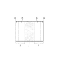
図1は、溶融塩電池における発電要素の基本構造を原理的に示す略図である。図において、発電要素は、正極1、負極2及びそれらの間に介在するセパレータ3を備えている。正極1は、正極集電体1aと、正極材1bとによって構成されている。負極2は、負極集電体2aと、負極材2bとによって構成されている。
Hereinafter, a molten salt assembled battery according to an embodiment of the present invention will be described with reference to the drawings.
<Basic structure of molten salt battery>
FIG. 1 is a schematic diagram showing in principle the basic structure of a power generation element in a molten salt battery. In the figure, the power generation element includes a
正極集電体1aの素材は、例えば、アルミニウム不織布(線径100μm、気孔率80%)である。正極材1bは、正極活物質としての例えばNaCrO2と、アセチレンブラックと、PVDF(ポリフッ化ビニリデン)と、N−メチル−2−ピロリドンとを、質量比85:10:5:50の割合で混練したものである。そして、このように混練したものを、アルミニウム不織布の正極集電体1aに充填し、乾燥後に、1000kgf/cm2にてプレスし、正極1の厚みが約1mmとなるように形成される。
一方、負極2においては、アルミニウム製の負極集電体2a上に、負極活物質としての例えば錫を含むSn−Na合金が、メッキにより形成される。
The material of the positive electrode current collector 1a is, for example, an aluminum nonwoven fabric (wire diameter: 100 μm, porosity: 80%). The
On the other hand, in the
正極1及び負極2の間に介在するセパレータ3は、ガラスの不織布(厚さ200μm)に電解質としての溶融塩を含浸させたものである。この溶融塩は、例えば、NaFSA(ナトリウム ビスフルオロスルフォニルアミド)0.45mol%と、KFSA(カリウム ビスフルオロスルフォニルアミド)0.55mol%との混合物であり、融点は57℃である。融点以上の温度では、溶融塩は溶融し、高濃度のイオンが溶解した電解液となって、正極1及び負極2に触れている。また、この溶融塩は不燃性である。この溶融塩電池の稼働温度領域は57℃〜190℃であり、通常は、85℃〜95℃に温度を維持して使用される。
The
なお、上述した各部の材質・成分や数値は好適な一例であるが、これらに限定されるものではない。
例えば、溶融塩としては、上記の他、LiFSA−KFSA−CsFSAの混合物も好適である。また、他の塩を混合する場合もあり(有機カチオン等)、一般には、溶融塩は、(a)NaFSA、又は、LiFSAを含む混合物、(b)NaTFSA、又は、LiTFSAを含む混合物、が適する。これらの場合、各混合物の溶融塩は、比較的低融点となるので、少ない加熱で溶融塩電池を作動させることができる。
In addition, although the material, component, and numerical value of each part mentioned above are suitable examples, it is not limited to these.
For example, in addition to the above, a mixture of LiFSA-KFSA-CsFSA is also suitable as the molten salt. In addition, other salts may be mixed (such as organic cations). Generally, (a) a mixture containing NaFSA or LiFSA or (b) a mixture containing NaTFSA or LiTFSA is suitable as the molten salt. . In these cases, since the molten salt of each mixture has a relatively low melting point, the molten salt battery can be operated with a small amount of heating.
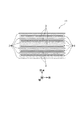
次に、より具体的な溶融塩電池の発電要素の構成について説明する。図2は、溶融塩電池本体(電池としての本体部分)10の積層構造を簡略に示す斜視図、図3は同様の構造についての横断面図である。
図2及び図3において、複数(図示しているのは6個)の矩形平板状の負極2と、袋状のセパレータ3に各々収容された複数(図示しているのは5個)の矩形平板状の正極1とが、互いに対向して図3における上下方向すなわち積層方向に重ね合わせられ、積層構造を成している。
Next, a more specific configuration of the power generation element of the molten salt battery will be described. FIG. 2 is a perspective view schematically showing a laminated structure of a molten salt battery main body (main body portion as a battery) 10, and FIG. 3 is a cross-sectional view of the same structure.
2 and 3, a plurality (six are shown) of rectangular flat plate-like
セパレータ3は、隣り合う正極1と負極2との間に介在しており、言い換えれば、セパレータ3を介して、正極1及び負極2が交互に積層されていることになる。実際に積層する数は、例えば、正極1が20個、負極2が21個、セパレータ3は「袋」としては20袋であるが、正極1・負極2間に介在する個数としては40個である。なお、セパレータ3は、袋状に限定されず、分離した40個であってもよい。
The
なお、図3では、セパレータ3と負極2とが互いに離れているように描いているが、溶融塩電池の完成時には互いに密着する。正極1も、当然に、セパレータ3に密着している。また、正極1の縦方向及び横方向それぞれの寸法は、デンドライトの発生を防止するために、負極2の縦方向及び横方向の寸法より小さくしてあり、正極1の外縁が、セパレータ3を介して負極2の周縁部に対向するようになっている。
In FIG. 3, the
上記のように構成された溶融塩電池本体10は、例えばアルミニウム合金製で直方体状の電池容器に収容され、素電池すなわち、電池としての物理的な一個体を成す。
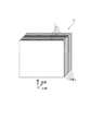
図4は、このような電池容器11に収められた状態の溶融塩電池Bの外観の概略を示す斜視図である。なお、図2,図3における正極1及び負極2のそれぞれからは、端子(正極1の端子1tのみ図示している。)が電池容器11の外部へ引き出される。図4において、電池容器11の上部には、内部の気圧が過度に上昇したときに放圧するための安全弁12が設けられている。なお、電池容器11の内面には絶縁処理が施されている。
The molten salt battery
FIG. 4 is a perspective view showing an outline of the appearance of the molten salt battery B in a state of being housed in such a
図4に示した溶融塩電池Bの一個体形状は、一例に過ぎず、形状・寸法は任意に構成することができる。例えば、電池容器11を平面視した形状を、円弧状に湾曲させることや、正方形に近づけることも可能である。また、端子1tは、電池容器11の上面に設けることも可能である。
上記のような溶融塩電池Bは、用途に必要な電圧や電流容量を得るべく、複数個が集まって互いに直列又は直並列に接続され、組電池を構成した状態で使用することができる。
The individual shape of the molten salt battery B shown in FIG. 4 is merely an example, and the shape and dimensions can be arbitrarily configured. For example, the shape of the
The molten salt battery B as described above can be used in a state where a plurality of batteries are gathered together and connected in series or in series and parallel to form a battery pack in order to obtain a voltage and current capacity necessary for the application.
《溶融塩組電池の構成例:第1実施形態》
図5〜8は、第1実施形態に係る溶融塩組電池に関する図である。図5は、複数の溶融塩電池Bによって溶融塩組電池20を構成する場合の、空間的な位置関係の一例を示す分解斜視図である。溶融塩組電池20は、断熱容器24内に、溶融塩電池B及び後述のヒータを装填して構成される。断熱容器24は、構造又は材質によって断熱性を有し、閉鎖可能な容器である。
<< Configuration Example of Molten Salt Assembly Battery: First Embodiment >>
5-8 is a figure regarding the molten salt assembled battery which concerns on 1st Embodiment. FIG. 5 is an exploded perspective view showing an example of a spatial positional relationship in the case where the molten salt assembled
図6は、図5における溶融塩組電池20の水平断面に相当する図であり、内部の構造の要部を簡略に示したものである。なお、図4における端子1t及び安全弁12、並びに、電池間の電気的な接続電路等、細部の構造については図示を省略している。
FIG. 6 is a view corresponding to a horizontal cross section of the molten salt assembled
図6において、この溶融塩組電池20を構成する複数の溶融塩電池は、その配置場所の違いから、4個の中心電池Bcと、4個の外側電池Boとに分けられる。中心電池Bcは、中央に設けられた第1のヒータ21に密着して、これを囲むように、配置されている。また、中心電池Bcの外面に密着してこれらを取り囲むように、第2のヒータ22が設けられている。第2のヒータ22は、例えば4枚のパネルヒータによって構成される。外側電池Boは、第2のヒータ22の外側に密着するように設けられている。また、外側電池Boの外面に密着してこれらを取り囲むように、第3のヒータ23が設けられている。第3のヒータ23は、例えば4枚のパネルヒータによって構成される。
In FIG. 6, the plurality of molten salt batteries constituting the molten salt assembled
なお、上記第1のヒータ21は、中心電池Bcを加熱する「中心電池用ヒータ」である。上記第3のヒータ23は、外側電池Boを加熱する「外側電池用ヒータ」である。上記第2のヒータ22は、中心電池Bcを加熱する中心電池用ヒータであるとともに、外側電池Boを加熱する外側電池用ヒータでもある。
The
以上の各部(第1のヒータ21、中心電池Bc、第2のヒータ22、外側電池Bo、第3のヒータ23)は、断熱容器24によって六面を覆われている。断熱容器24は、好ましくは、肉厚方向の中間に真空層を挟んだ魔法瓶構造の壁材によって構成されている。
Each of the above parts (the
なお、上記中心電池Bc、外側電池Boのそれぞれの数量は、単に一例を示したに過ぎず、数量は任意に変更し得る。基本的には、相対的に中心側にある中心電池Bcと、相対的に外側にある外側電池Boとを含む構成であればよい。
なお、図6に示す構成は、高さ方向(図6の紙面に垂直方向)へ複数段にわたって、中心電池Bc及び外側電池Boを設けることも可能である。
The quantities of the central battery Bc and the outer battery Bo are merely examples, and the quantities can be arbitrarily changed. Basically, it may be configured to include the central battery Bc relatively on the center side and the outer battery Bo relatively on the outside.
In the configuration shown in FIG. 6, the central battery Bc and the outer battery Bo can be provided in a plurality of stages in the height direction (perpendicular to the paper surface of FIG. 6).
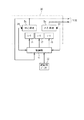
図7は、溶融塩組電池20のヒータ制御に関するブロック図である。溶融塩組電池20は、前述の中心電池Bc、外側電池Bo、3つのヒータ21〜23の他、中心電池Bcの温度を測定する温度センサ24及び、外側電池Boの温度を測定する温度センサ25を備えている。これらの温度センサ24,25は、例えば、図6における中心電池Bc及び外側電池Boのそれぞれにおける少なくとも1つの電池容器11(図4)に、外面から当接して設けられる。
FIG. 7 is a block diagram relating to heater control of the molten salt assembled
温度センサ24,25の出力信号は、制御部31に入力される。制御部31は、各ヒータ21〜23を制御する。制御部31には起動用バッテリ32から電圧が入力されており、これを、中心電池Bcの起動用に用いることができる。また、中心電池Bcの出力する電圧は、制御部31に入力可能なように接続されている。電解質が溶融した中心電池Bc及び外側電池Boの各電圧は、出力として、溶融塩組電池20の外部へ取り出すことができる。
Output signals from the
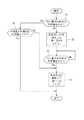
図8は、制御部31によって実行される、ウォームアップの手順を示すフローチャートである。図において、まず、制御部31は、中心電池Bcの温度が所定値以上か否かを判断する(ステップS1)。所定値とは、例えば、前述のNaFSA−KFSAの電解質であれば、その融点である57℃である。但し、若干の余裕をみて、57℃より少し上の値としてもよい。稼働停止後一定時間以上経過して中心電池Bcの温度が所定値未満に下がっている場合には、制御部31は、起動用バッテリ32を使用して、第1,第2のヒータ21,22をオンにする(ステップS2)。これにより中心電池Bcが加熱される。また、第2のヒータ22により、外側電池Boも、ある程度加熱される。制御部31は、中心電池Bcの温度が所定値(ステップS1の所定値と同一値)以上か否かを繰り返し監視する(ステップS3)。
FIG. 8 is a flowchart showing a warm-up procedure executed by the
ここで、4個の中心電池Bcの体積(総和)は、4個の外側電池Boの体積(総和)よりも小さい。従って、4個の中心電池Bcの熱容量(総和)は、4個の外側電池Boの熱容量(総和)よりも小さい。この熱容量の小ささと、第1のヒータ21及び第2のヒータ22による加熱によって、中心電池Bcは、外側電池Boよりも急速に温度が上昇し、迅速に、電解質の融点に達する。こうして、中心電池Bcの温度が所定値以上になると、制御部31は、中心電池Bcの出力を用いて、第3のヒータ23をオンにする(ステップS4)。また、第1及び第2のヒータ21,22への給電についても、起動用バッテリ32から中心電池Bcに切り替えることができる。第2のヒータ22及び第3のヒータ23の加熱により、外側電池Boの温度が上昇し、電解質の融点に達する。これにより、全ての電池Bc,Boが稼働する状態となり、ウォームアップは終了となる。
Here, the volume (total) of the four central batteries Bc is smaller than the volume (total) of the four outer batteries Bo. Accordingly, the heat capacities (total) of the four central batteries Bc are smaller than the heat capacities (total) of the four outer batteries Bo. Due to the small heat capacity and the heating by the
一方、ステップS1において中心電池Bcが所定値以上の温度であれば、制御部31は、次に、外側電池Boの温度が所定値(ステップS1と同じ)以上であるか否かを判断し(ステップS5)、所定値未満であれば、中心電池Bcを使用して第1〜第3のヒータ21,22,23をオンの状態として外側電池Boを加熱する。また、ステップS5において所定値以上であれば、もはや特にウォームアップは必要ない状態であるので、処理終了となる。
なお、ウォームアップ終了後の中心電池Bc及び外側電池Boの加熱(若しくは保温)については、ここでは省略するが、充放電により各電池が自己発熱するので、加熱不要になる場合もある。
On the other hand, if the temperature of the central battery Bc is equal to or higher than a predetermined value in step S1, the
The heating (or heat retention) of the central battery Bc and the outer battery Bo after the warm-up is omitted here, but each battery self-heats due to charging / discharging, and thus heating may be unnecessary.
また、電池の稼働を停止させた後は、全てのヒータ21〜23がオフとなり、中心電池Bc及び外側電池Boは共に徐々に冷えていく。ここで、中心電池Bcは、断熱容器の中心側にあるので、外側電池Boに比べて放熱しにくく、従って、冷めにくい。停止後短時間で再度電池が起動されるときは、この冷めにくさが役立ち、中心電池Bcの温度が相対的に高く、従って、ウォームアップを迅速に行うことができる。
In addition, after the operation of the battery is stopped, all the
このように、上記のように構成された溶融塩組電池20では、熱容量が小さい中心電池Bcは外側電池Boに比べて加熱により昇温しやすい。また、中心電池Bcは、中心側にあることにより外側電池Boよりも放熱しにくいので、電池としての稼働を停止した後も、冷めにくく、従って、再起動時に有利である。
Thus, in the molten salt assembled
そこで、溶融塩組電池20の起動時に、まず、中心電池Bcのみを加熱することによって、迅速に、中心電池Bcの電解質を溶融させ、電池として起動させることができる。すなわち、外側電池Boを含む全体を加熱するよりも、中心電池Bcのみを加熱することにより、一部(中心電池)とはいえ、溶融塩組電池20から出力可能となるまでのウォームアップ時間を短縮することができる。
Therefore, when the molten salt assembled
また、中心電池Bcが起動すれば、その出力を各ヒータ21〜23に使用することができる。従って、起動用の補助的なバッテリ32の電力負担は軽減される。
こうして、溶融塩組電池から出力可能になるまでのウォームアップ時間の短縮と、補助的なバッテリの負担軽減とを実現することができる。
Moreover, if the central battery Bc is started, the output can be used for each heater 21-23. Therefore, the power load of the
In this way, it is possible to reduce the warm-up time until output from the molten salt assembled battery becomes possible and reduce the burden on the auxiliary battery.
なお、このように第1のヒータ21(中心電池用ヒータ)が断熱容器24の中心に配置され、当該ヒータ21を中心電池Bcが取り囲んでいる構成は、複数の溶融塩電池を中心電池Bcとして中心のヒータ21で加熱することに適した構成(複数の溶融塩電池をヒータ21の周りに並べることに適した構成)となる。
The first heater 21 (central battery heater) is arranged in the center of the
《溶融塩組電池の構成例:第2実施形態》
図9は、第1実施形態における図6に対応する第2実施形態に係る溶融塩組電池20の水平断面に相当する図であり、内部の構造の要部を簡略に示したものである。なお、図4における端子1t及び安全弁12、並びに、電池間の電気的な接続電路等、細部の構造については図示を省略している。
<< Configuration Example of Molten Salt Battery: Second Embodiment >>
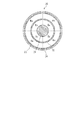
FIG. 9 is a view corresponding to a horizontal cross section of the molten salt assembled
図6において、この溶融塩組電池20は、円柱(円筒)形状を基調とした形状となっており、最も内側の第1のヒータ21から順に、径方向外側へ、中心電池Bc、第2のヒータ22、外側電池Bo、第3のヒータ23、断熱容器24が同心円筒状に設けられている。中心電池Bc及び外側電池Boはそれぞれ、周方向に4等分された、上から見て円弧状の形態となっているが、個数は一例に過ぎない。また、第2のヒータ22及び第3のヒータ23はそれぞれ、何等分かの円弧状のパネルヒータの集合体によって構成されていてもよいし、円筒形状のヒータであってもよい。
In FIG. 6, this molten salt assembled
なお、図9における第1のヒータ21は、中心電池Bcを加熱する「中心電池用ヒータ」である。第3のヒータ23は、外側電池Boを加熱する「外側電池用ヒータ」である。第2のヒータ22は、中心電池Bcを加熱する中心電池用ヒータであるとともに、外側電池Boを加熱する外側電池用ヒータでもある。
Note that the
以上の各部(第1のヒータ21、中心電池Bc、第2のヒータ22、外側電池Bo、第3のヒータ23)は、断熱容器24によって円柱状の外面及び軸方向両端面を覆われている。断熱容器24は、好ましくは、肉厚方向の中間に真空層を挟んだ魔法瓶構造の壁材によって構成されている。
Each of the above parts (the
ここで、4個の中心電池Bcの体積(総和)は、4個の外側電池Boの体積(総和)よりも小さい。従って、4個の中心電池Bcの熱容量(総和)は、4個の外側電池Boの熱容量(総和)よりも小さい。この熱容量の小ささと、第1のヒータ21及び第2のヒータ22による加熱によって、中心電池Bcは、外側電池Boよりも急速に温度が上昇し、迅速に、電解質の融点に達する。従って、第1実施形態と同様のヒータ制御を行ってウォームアップすることができ、同様の作用効果を奏する。
また、図9の構成は、円柱(円筒)形状を基調とすることによって、電池容量の割に、全体として外形寸法が小さいコンパクトな溶融塩組電池20とすることができる。
Here, the volume (total) of the four central batteries Bc is smaller than the volume (total) of the four outer batteries Bo. Accordingly, the heat capacities (total) of the four central batteries Bc are smaller than the heat capacities (total) of the four outer batteries Bo. Due to the small heat capacity and the heating by the
Moreover, the structure of FIG. 9 can be made into the compact molten salt assembled
《溶融塩組電池の構成例:第3実施形態》
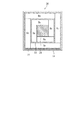
図10は、第1実施形態における図6に対応する第3実施形態に係る溶融塩組電池20の水平断面に相当する図であり、内部の構造の要部を簡略に示したものである。なお、図4における端子1t及び安全弁12、並びに、電池間の電気的な接続電路等、細部の構造については図示を省略している。
<< Configuration Example of Molten Salt Assembly Battery: Third Embodiment >>
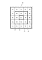
FIG. 10 is a view corresponding to a horizontal cross section of the molten salt assembled
図10において、この溶融塩組電池20は、マトリックス形状を基調とした形状となっており、中心に位置する第1のヒータ21を8個の中心電池Bcが取り囲み、それらの外面に第2のヒータ22(太線で示す。)が設けられている。第2のヒータ22の外側には、16個の外側電池Boが配置され、さらにそれらの外面に、第3のヒータ23(太線で示す。)が設けられている。第3のヒータ23の外側には、断熱容器24が設けられている。なお、電池の個数は一例に過ぎない。
In FIG. 10, this molten salt assembled
なお、図10において、第1のヒータ21は、中心電池Bcを加熱する「中心電池用ヒータ」である。第3のヒータ23は、外側電池Boを加熱する「外側電池用ヒータ」である。第2のヒータ22は、中心電池Bcを加熱する中心電池用ヒータであるとともに、外側電池Boを加熱する外側電池用ヒータでもある。
In FIG. 10, the
以上の各部(第1のヒータ21、中心電池Bc、第2のヒータ22、外側電池Bo、第3のヒータ23)は、断熱容器24によって六面を覆われている。断熱容器24は、好ましくは、肉厚方向の中間に真空層を挟んだ魔法瓶構造の壁材によって構成されている。
Each of the above parts (the
ここで、8個の中心電池Bcの体積(総和)は、16個の外側電池Boの体積(総和)よりも小さい。従って、8個の中心電池Bcの熱容量(総和)は、16個の外側電池Boの熱容量(総和)よりも小さい。この熱容量の小ささと、第1のヒータ21及び第2のヒータ22による加熱によって、中心電池Bcは、外側電池Boよりも急速に温度が上昇し、迅速に、電解質の融点に達する。従って、第1実施形態と同様のヒータ制御を行ってウォームアップすることができ、同様の作用効果を奏する。
Here, the volume (total) of the eight central batteries Bc is smaller than the volume (total) of the sixteen outer batteries Bo. Accordingly, the heat capacities (total) of the eight central batteries Bc are smaller than the heat capacities (total) of the sixteen outer batteries Bo. Due to the small heat capacity and the heating by the
なお、このように第1のヒータ21(中心電池用ヒータ)が断熱容器24の中心に配置され、当該ヒータ21を中心電池Bcが取り囲んでいる構成は、第1実施形態と同様に、複数の溶融塩電池を中心電池Bcとして中心のヒータ21で加熱することに適した構成となる。
The first heater 21 (center battery heater) is arranged at the center of the
《溶融塩組電池の構成例:第4実施形態》
図11は、第1実施形態における図6に対応する第4実施形態に係る溶融塩組電池20の水平断面に相当する図であり、内部の構造の要部を簡略に示したものである。なお、図4における端子1t及び安全弁12、並びに、電池間の電気的な接続電路等、細部の構造については図示を省略している。
<< Configuration Example of Molten Salt Assembly Battery: Fourth Embodiment >>
FIG. 11 is a view corresponding to a horizontal cross section of the molten salt assembled
図11において、この溶融塩組電池20は、第3実施形態と同様に、マトリックス形状を基調とした形状となっており、中心に位置する1個の中心電池Bcの外面を第1のヒータ21(太線で示す。)で囲んでいる。さらにその外側には、8個の中間電池Bmが設けられている。中間電池Bmは、中心電池Bcと、外側電池Boとの中間的な意義を有する。中間電池Bmの外側には第2のヒータ22(太線で示す。)が設けられている。第2のヒータ22の外側には、16個の外側電池Boが配置され、さらにそれらの外面に、第3のヒータ23(太線で示す。)が設けられている。第3のヒータ23の外側には、断熱容器24が設けられている。なお、電池の個数は一例に過ぎない。このような構成の場合、中心部の空間をヒータが占有しないので、その分、電池容量の割に、溶融塩組電池20をコンパクトに構成することができる。
In FIG. 11, the molten salt assembled
なお、図11において、第1のヒータ21は、主として中心電池Bcを加熱する「中心電池用ヒータ」であるが、中間電池Bmの加熱にも寄与する。第2のヒータ22は、中間電池Bmを加熱するヒータであるとともに、外側電池Boを加熱する「外側電池用ヒータ」でもある。また、第3のヒータ23は、外側電池Boを加熱する「外側電池用ヒータ」である。
In FIG. 11, the
以上の各部(第1のヒータ21、中心電池Bc、第2のヒータ22、外側電池Bo、第3のヒータ23)は、断熱容器24によって六面を覆われている。断熱容器24は、好ましくは、肉厚方向の中間に真空層を挟んだ魔法瓶構造の壁材によって構成されている。
Each of the above parts (the
ここで、1個の中心電池Bcの体積は、8個の中間電池Bcの体積(総和)及び16個の外側電池Boの体積(総和)よりも圧倒的に小さい。従って、中心電池Bcの熱容量(総和)は、合計24個の中間電池Bm及び外側電池Boの熱容量(総和)よりも極めて小さい。この熱容量の小ささによって、中心電池Bcは、中間電池Bmや外側電池Boよりも急速に温度が上昇し、迅速に、電解質の融点に達する。従って、第1実施形態と同様のヒータ制御を行ってウォームアップすることができ、同様の作用効果を奏する。 Here, the volume of one central battery Bc is overwhelmingly smaller than the volume (total) of the eight intermediate batteries Bc and the volume (total) of the sixteen outer batteries Bo. Accordingly, the heat capacity (total) of the central battery Bc is extremely smaller than the heat capacities (total) of the total 24 intermediate batteries Bm and the outer battery Bo. Due to the small heat capacity, the temperature of the central battery Bc rises more rapidly than the intermediate battery Bm and the outer battery Bo, and quickly reaches the melting point of the electrolyte. Therefore, the heater control similar to that of the first embodiment can be performed to warm up, and the same effects can be obtained.
但し、起動時の、起動用バッテリ32からの給電は、第1のヒータ21のみでよい。そして、中心電池Bcが起動すれば、中心電池Bcから第2のヒータ22及び第3のヒータ23に給電開始するほか、第1のヒータ21への給電も、中心電池Bcから行うことができる。
However, only the
なお、この場合、電解質が溶融する順序は、中心電池Bc、中間電池Bm、外側電池Boの順となる。従って、中心電池Bcが迅速に出力開始となって、漸次、出力が増大していくので、中心電池Bcの起動により中心電池Bcから第1のヒータ21,第2のヒータ22に給電し、中間電池Bmの起動により、中心電池Bcと中間電池Bmとによって、全てのヒータ21〜23に給電する、という電力供給形態も可能である。
In this case, the order of melting of the electrolyte is the order of the central battery Bc, the intermediate battery Bm, and the outer battery Bo. Accordingly, the output of the central battery Bc starts quickly, and the output gradually increases. Therefore, the central battery Bc is activated to supply power to the
《その他》
なお、今回開示された実施の形態はすべての点で例示であって制限的なものではないと考えられるべきである。本発明の範囲は特許請求の範囲によって示され、特許請求の範囲と均等の意味及び範囲内での全ての変更が含まれることが意図される。
<Others>
The embodiment disclosed this time should be considered as illustrative in all points and not restrictive. The scope of the present invention is defined by the terms of the claims, and is intended to include any modifications within the scope and meaning equivalent to the terms of the claims.
20:溶融塩組電池
21:第1のヒータ(中心電池用ヒータ)
22:第2のヒータ
23:第3のヒータ(外側電池用ヒータ)
24:断熱容器
B:溶融塩電池
Bc:中心電池
Bo:外側電池
20: Molten salt assembled battery 21: First heater (heater for central battery)
22: Second heater 23: Third heater (outer battery heater)
24: Thermal insulation container B: Molten salt battery Bc: Central battery Bo: Outer battery
Claims (5)
前記溶融塩電池によって構成され、当該溶融塩組電池内で相対的に外側に位置する外側電池と、
前記溶融塩電池によって構成され、前記外側電池よりも相対的に中心側に位置し、前記外側電池より熱容量が小さい中心電池と、
前記中心電池を加熱する中心電池用ヒータと、
前記外側電池を加熱する外側電池用ヒータと、
前記外側電池の外面を覆う断熱容器と
を備えていることを特徴とする溶融塩組電池。 A molten salt battery comprising a plurality of molten salt batteries containing molten salt as an electrolyte,
An outer battery constituted by the molten salt battery and positioned relatively outside in the molten salt battery;
A central battery that is constituted by the molten salt battery, is positioned relatively on the center side than the outer battery, and has a smaller heat capacity than the outer battery;
A central battery heater for heating the central battery;
An outer battery heater for heating the outer battery;
A molten salt assembled battery comprising: a heat insulating container that covers an outer surface of the outer battery.
前記中心電池用ヒータに給電することにより、前記中心電池を加熱して電解質を溶融させ、
前記中心電池の出力を用いて前記外側電池用ヒータに給電することにより、前記外側電池を加熱して電解質を溶融させる
ことを特徴とする溶融塩組電池のウォームアップ方法。 A molten salt battery including a plurality of molten salt batteries containing a molten salt as an electrolyte, the outer battery being constituted by the molten salt battery and positioned relatively outside in the molten salt battery; A central battery that is constituted by the molten salt battery and is located relatively centrally with respect to the outer battery and has a smaller heat capacity than the outer battery, a heater for the central battery that heats the central battery, and the outer battery. A warm-up method for starting up a heater for an outer battery to be heated and a heat insulating container covering an outer surface of the outer battery,
By feeding power to the central battery heater, the central battery is heated to melt the electrolyte,
A method for warming up a molten salt assembled battery, wherein the outer battery is heated by supplying power to the heater for the outer battery using the output of the central battery to melt the electrolyte.
Priority Applications (1)
| Application Number | Priority Date | Filing Date | Title |
|---|---|---|---|
| JP2011116168A JP2012243732A (en) | 2011-05-24 | 2011-05-24 | Molten salt battery pack and warm-up method thereof |
Applications Claiming Priority (1)
| Application Number | Priority Date | Filing Date | Title |
|---|---|---|---|
| JP2011116168A JP2012243732A (en) | 2011-05-24 | 2011-05-24 | Molten salt battery pack and warm-up method thereof |
Publications (1)
| Publication Number | Publication Date |
|---|---|
| JP2012243732A true JP2012243732A (en) | 2012-12-10 |
Family
ID=47465181
Family Applications (1)
| Application Number | Title | Priority Date | Filing Date |
|---|---|---|---|
| JP2011116168A Pending JP2012243732A (en) | 2011-05-24 | 2011-05-24 | Molten salt battery pack and warm-up method thereof |
Country Status (1)
| Country | Link |
|---|---|
| JP (1) | JP2012243732A (en) |
Cited By (4)
| Publication number | Priority date | Publication date | Assignee | Title |
|---|---|---|---|---|
| WO2013061979A2 (en) * | 2011-10-26 | 2013-05-02 | 住友電気工業株式会社 | Molten salt battery device, and control method for molten salt battery device |
| JP2016110937A (en) * | 2014-12-10 | 2016-06-20 | トヨタ自動車株式会社 | Secondary battery heater structure |
| US20170346089A1 (en) * | 2014-12-26 | 2017-11-30 | Sanyo Electric Co., Ltd. | Battery pack |
| WO2018062759A1 (en) * | 2016-09-29 | 2018-04-05 | 주식회사 엘지화학 | Battery module |
Citations (5)
| Publication number | Priority date | Publication date | Assignee | Title |
|---|---|---|---|---|
| JPH06231801A (en) * | 1993-02-01 | 1994-08-19 | Seiko Epson Corp | High-temperature type storage battery |
| JPH0935725A (en) * | 1995-07-19 | 1997-02-07 | Mitsubishi Heavy Ind Ltd | High temperature operation type battery having heat conductive plate |
| JPH09306552A (en) * | 1996-05-20 | 1997-11-28 | Mitsubishi Heavy Ind Ltd | High temperature operation battery apparatus |
| JP2006278337A (en) * | 2005-03-25 | 2006-10-12 | Samsung Sdi Co Ltd | Battery module |
| WO2011006315A1 (en) * | 2009-07-17 | 2011-01-20 | 清华大学 | Battery pack and toroidal battery cell to be used therefor |
-
2011
- 2011-05-24 JP JP2011116168A patent/JP2012243732A/en active Pending
Patent Citations (5)
| Publication number | Priority date | Publication date | Assignee | Title |
|---|---|---|---|---|
| JPH06231801A (en) * | 1993-02-01 | 1994-08-19 | Seiko Epson Corp | High-temperature type storage battery |
| JPH0935725A (en) * | 1995-07-19 | 1997-02-07 | Mitsubishi Heavy Ind Ltd | High temperature operation type battery having heat conductive plate |
| JPH09306552A (en) * | 1996-05-20 | 1997-11-28 | Mitsubishi Heavy Ind Ltd | High temperature operation battery apparatus |
| JP2006278337A (en) * | 2005-03-25 | 2006-10-12 | Samsung Sdi Co Ltd | Battery module |
| WO2011006315A1 (en) * | 2009-07-17 | 2011-01-20 | 清华大学 | Battery pack and toroidal battery cell to be used therefor |
Cited By (5)
| Publication number | Priority date | Publication date | Assignee | Title |
|---|---|---|---|---|
| WO2013061979A2 (en) * | 2011-10-26 | 2013-05-02 | 住友電気工業株式会社 | Molten salt battery device, and control method for molten salt battery device |
| WO2013061979A3 (en) * | 2011-10-26 | 2013-07-04 | 住友電気工業株式会社 | Molten salt battery device, and control method for molten salt battery device |
| JP2016110937A (en) * | 2014-12-10 | 2016-06-20 | トヨタ自動車株式会社 | Secondary battery heater structure |
| US20170346089A1 (en) * | 2014-12-26 | 2017-11-30 | Sanyo Electric Co., Ltd. | Battery pack |
| WO2018062759A1 (en) * | 2016-09-29 | 2018-04-05 | 주식회사 엘지화학 | Battery module |
Similar Documents
| Publication | Publication Date | Title |
|---|---|---|
| JP6567553B2 (en) | Battery pack | |
| US9018909B2 (en) | Battery pack | |
| JP5618356B2 (en) | Battery unit and power supply | |
| JP7007297B2 (en) | Pressurized Lithium Metal Polymer Battery | |
| JP2014183013A (en) | Battery pack | |
| WO2013161549A1 (en) | Molten salt cell system | |
| WO2014024708A1 (en) | Industrial vehicle and power source device thereof | |
| JP2012243732A (en) | Molten salt battery pack and warm-up method thereof | |
| KR101769109B1 (en) | Battery pack including cartridge for secondary battery | |
| WO2013061979A2 (en) | Molten salt battery device, and control method for molten salt battery device | |
| JP5617746B2 (en) | Closed molten salt battery | |
| JP2014089915A (en) | Power supply system and electric vehicle | |
| JP2015138648A (en) | battery module | |
| CN109244599B (en) | Composite negative pole piece with rapid heating function, and battery cell and battery adopting composite negative pole piece | |
| JP2018085166A (en) | Hybrid capacitor battery | |
| CN214797540U (en) | Annular lithium ion battery pack with thermal management function | |
| JP2003068356A (en) | Secondary sodium battery, aggregate of batteries and its module | |
| JP2014011061A (en) | Molten salt battery system | |
| JP2014051394A (en) | Industrial vehicle, and electric power unit thereof | |
| JP2015076918A (en) | Power supply device and electrically propelled vehicle | |
| WO2013051385A1 (en) | Emergency molten salt assembly cell and method for using same, and emergency power supply device | |
| JP2013109938A (en) | Method for manufacturing molten salt battery | |
| JP2012190543A (en) | Molten-salt battery device and control method of molten-salt battery | |
| CN108879028B (en) | Solid-state lithium battery based on spiral heating rod and heating device and heating control method thereof | |
| JP5880275B2 (en) | Power storage device and secondary battery |
Legal Events
| Date | Code | Title | Description |
|---|---|---|---|
| A621 | Written request for application examination |
Free format text: JAPANESE INTERMEDIATE CODE: A621 Effective date: 20131225 |
|
| A02 | Decision of refusal |
Free format text: JAPANESE INTERMEDIATE CODE: A02 Effective date: 20150303 |