JP2012243455A - Lithium ion secondary battery - Google Patents
Lithium ion secondary battery Download PDFInfo
- Publication number
- JP2012243455A JP2012243455A JP2011110360A JP2011110360A JP2012243455A JP 2012243455 A JP2012243455 A JP 2012243455A JP 2011110360 A JP2011110360 A JP 2011110360A JP 2011110360 A JP2011110360 A JP 2011110360A JP 2012243455 A JP2012243455 A JP 2012243455A
- Authority
- JP
- Japan
- Prior art keywords
- negative electrode
- active material
- current collector
- electrode active
- material layer
- Prior art date
- Legal status (The legal status is an assumption and is not a legal conclusion. Google has not performed a legal analysis and makes no representation as to the accuracy of the status listed.)
- Withdrawn
Links
- HBBGRARXTFLTSG-UHFFFAOYSA-N Lithium ion Chemical compound [Li+] HBBGRARXTFLTSG-UHFFFAOYSA-N 0.000 title claims abstract description 131
- 229910001416 lithium ion Inorganic materials 0.000 title claims abstract description 131
- 229910052744 lithium Inorganic materials 0.000 claims abstract description 135
- WHXSMMKQMYFTQS-UHFFFAOYSA-N Lithium Chemical compound [Li] WHXSMMKQMYFTQS-UHFFFAOYSA-N 0.000 claims abstract description 131
- 239000007773 negative electrode material Substances 0.000 claims abstract description 113
- 239000007774 positive electrode material Substances 0.000 claims abstract description 65
- 238000004804 winding Methods 0.000 claims abstract description 18
- 230000002441 reversible effect Effects 0.000 claims description 20
- 239000011888 foil Substances 0.000 claims description 13
- 229910052751 metal Inorganic materials 0.000 abstract description 67
- 239000002184 metal Substances 0.000 abstract description 67
- 238000007600 charging Methods 0.000 abstract description 13
- 239000010410 layer Substances 0.000 description 125
- 239000008151 electrolyte solution Substances 0.000 description 24
- 239000011230 binding agent Substances 0.000 description 23
- 238000000034 method Methods 0.000 description 20
- OKTJSMMVPCPJKN-UHFFFAOYSA-N Carbon Chemical compound [C] OKTJSMMVPCPJKN-UHFFFAOYSA-N 0.000 description 16
- 239000004020 conductor Substances 0.000 description 16
- 239000000203 mixture Substances 0.000 description 16
- 239000002245 particle Substances 0.000 description 16
- 238000010586 diagram Methods 0.000 description 12
- 239000000463 material Substances 0.000 description 9
- SECXISVLQFMRJM-UHFFFAOYSA-N N-Methylpyrrolidone Chemical group CN1CCCC1=O SECXISVLQFMRJM-UHFFFAOYSA-N 0.000 description 8
- 239000003125 aqueous solvent Substances 0.000 description 8
- 239000003575 carbonaceous material Substances 0.000 description 8
- 239000002904 solvent Substances 0.000 description 8
- 239000002033 PVDF binder Substances 0.000 description 6
- 238000007599 discharging Methods 0.000 description 6
- 229920002981 polyvinylidene fluoride Polymers 0.000 description 6
- 238000003466 welding Methods 0.000 description 6
- 239000004743 Polypropylene Substances 0.000 description 5
- 230000003750 conditioning effect Effects 0.000 description 5
- 230000000694 effects Effects 0.000 description 5
- 239000003792 electrolyte Substances 0.000 description 5
- 229910002804 graphite Inorganic materials 0.000 description 5
- 239000010439 graphite Substances 0.000 description 5
- 229920001155 polypropylene Polymers 0.000 description 5
- -1 polytetrafluoroethylene Polymers 0.000 description 5
- 239000002562 thickening agent Substances 0.000 description 5
- KMTRUDSVKNLOMY-UHFFFAOYSA-N Ethylene carbonate Chemical compound O=C1OCCO1 KMTRUDSVKNLOMY-UHFFFAOYSA-N 0.000 description 4
- 229910010707 LiFePO 4 Inorganic materials 0.000 description 4
- 239000004698 Polyethylene Substances 0.000 description 4
- 229910052782 aluminium Inorganic materials 0.000 description 4
- XAGFODPZIPBFFR-UHFFFAOYSA-N aluminium Chemical compound [Al] XAGFODPZIPBFFR-UHFFFAOYSA-N 0.000 description 4
- 230000007423 decrease Effects 0.000 description 4
- 238000002347 injection Methods 0.000 description 4
- 239000007924 injection Substances 0.000 description 4
- 229920000573 polyethylene Polymers 0.000 description 4
- 229920000642 polymer Polymers 0.000 description 4
- 238000005096 rolling process Methods 0.000 description 4
- 229920003048 styrene butadiene rubber Polymers 0.000 description 4
- 239000002174 Styrene-butadiene Substances 0.000 description 3
- 239000006230 acetylene black Substances 0.000 description 3
- 239000006229 carbon black Substances 0.000 description 3
- 235000019241 carbon black Nutrition 0.000 description 3
- JBTWLSYIZRCDFO-UHFFFAOYSA-N ethyl methyl carbonate Chemical compound CCOC(=O)OC JBTWLSYIZRCDFO-UHFFFAOYSA-N 0.000 description 3
- 239000007788 liquid Substances 0.000 description 3
- 239000012046 mixed solvent Substances 0.000 description 3
- 239000010450 olivine Substances 0.000 description 3
- 229910052609 olivine Inorganic materials 0.000 description 3
- 239000002861 polymer material Substances 0.000 description 3
- 229920005989 resin Polymers 0.000 description 3
- 239000011347 resin Substances 0.000 description 3
- RYGMFSIKBFXOCR-UHFFFAOYSA-N Copper Chemical compound [Cu] RYGMFSIKBFXOCR-UHFFFAOYSA-N 0.000 description 2
- 229910012851 LiCoO 2 Inorganic materials 0.000 description 2
- 229910015643 LiMn 2 O 4 Inorganic materials 0.000 description 2
- 229910013290 LiNiO 2 Inorganic materials 0.000 description 2
- 229910013870 LiPF 6 Inorganic materials 0.000 description 2
- 239000004372 Polyvinyl alcohol Substances 0.000 description 2
- 239000011149 active material Substances 0.000 description 2
- 239000000654 additive Substances 0.000 description 2
- 230000000996 additive effect Effects 0.000 description 2
- 229910052799 carbon Inorganic materials 0.000 description 2
- 239000002131 composite material Substances 0.000 description 2
- 238000010280 constant potential charging Methods 0.000 description 2
- 229920001577 copolymer Polymers 0.000 description 2
- 239000011889 copper foil Substances 0.000 description 2
- IEJIGPNLZYLLBP-UHFFFAOYSA-N dimethyl carbonate Chemical compound COC(=O)OC IEJIGPNLZYLLBP-UHFFFAOYSA-N 0.000 description 2
- 230000005611 electricity Effects 0.000 description 2
- 230000001747 exhibiting effect Effects 0.000 description 2
- 229920003088 hydroxypropyl methyl cellulose Polymers 0.000 description 2
- 239000001866 hydroxypropyl methyl cellulose Substances 0.000 description 2
- 235000010979 hydroxypropyl methyl cellulose Nutrition 0.000 description 2
- UFVKGYZPFZQRLF-UHFFFAOYSA-N hydroxypropyl methyl cellulose Chemical compound OC1C(O)C(OC)OC(CO)C1OC1C(O)C(O)C(OC2C(C(O)C(OC3C(C(O)C(O)C(CO)O3)O)C(CO)O2)O)C(CO)O1 UFVKGYZPFZQRLF-UHFFFAOYSA-N 0.000 description 2
- 239000005001 laminate film Substances 0.000 description 2
- 238000005259 measurement Methods 0.000 description 2
- 229910021382 natural graphite Inorganic materials 0.000 description 2
- 229920002239 polyacrylonitrile Polymers 0.000 description 2
- 229920001343 polytetrafluoroethylene Polymers 0.000 description 2
- 239000004810 polytetrafluoroethylene Substances 0.000 description 2
- 229920002451 polyvinyl alcohol Polymers 0.000 description 2
- 238000007789 sealing Methods 0.000 description 2
- 239000002002 slurry Substances 0.000 description 2
- 229910000838 Al alloy Inorganic materials 0.000 description 1
- 229920000049 Carbon (fiber) Polymers 0.000 description 1
- 229920002134 Carboxymethyl cellulose Polymers 0.000 description 1
- OIFBSDVPJOWBCH-UHFFFAOYSA-N Diethyl carbonate Chemical compound CCOC(=O)OCC OIFBSDVPJOWBCH-UHFFFAOYSA-N 0.000 description 1
- YCKRFDGAMUMZLT-UHFFFAOYSA-N Fluorine atom Chemical compound [F] YCKRFDGAMUMZLT-UHFFFAOYSA-N 0.000 description 1
- 229910000733 Li alloy Inorganic materials 0.000 description 1
- 229910015014 LiNiCoAlO Inorganic materials 0.000 description 1
- FAPWRFPIFSIZLT-UHFFFAOYSA-M Sodium chloride Chemical group [Na+].[Cl-] FAPWRFPIFSIZLT-UHFFFAOYSA-M 0.000 description 1
- SOXUFMZTHZXOGC-UHFFFAOYSA-N [Li].[Mn].[Co].[Ni] Chemical compound [Li].[Mn].[Co].[Ni] SOXUFMZTHZXOGC-UHFFFAOYSA-N 0.000 description 1
- NIXOWILDQLNWCW-UHFFFAOYSA-N acrylic acid group Chemical group C(C=C)(=O)O NIXOWILDQLNWCW-UHFFFAOYSA-N 0.000 description 1
- 239000000853 adhesive Substances 0.000 description 1
- 230000001070 adhesive effect Effects 0.000 description 1
- 239000002194 amorphous carbon material Substances 0.000 description 1
- 239000004917 carbon fiber Substances 0.000 description 1
- 239000001913 cellulose Substances 0.000 description 1
- 229920002678 cellulose Polymers 0.000 description 1
- 238000010277 constant-current charging Methods 0.000 description 1
- 238000010281 constant-current constant-voltage charging Methods 0.000 description 1
- 239000000470 constituent Substances 0.000 description 1
- 238000000354 decomposition reaction Methods 0.000 description 1
- QHGJSLXSVXVKHZ-UHFFFAOYSA-N dilithium;dioxido(dioxo)manganese Chemical compound [Li+].[Li+].[O-][Mn]([O-])(=O)=O QHGJSLXSVXVKHZ-UHFFFAOYSA-N 0.000 description 1
- 229920001971 elastomer Polymers 0.000 description 1
- 238000004049 embossing Methods 0.000 description 1
- 239000000945 filler Substances 0.000 description 1
- 239000011737 fluorine Substances 0.000 description 1
- 229910052731 fluorine Inorganic materials 0.000 description 1
- 239000000446 fuel Substances 0.000 description 1
- 229910021469 graphitizable carbon Inorganic materials 0.000 description 1
- 229910021385 hard carbon Inorganic materials 0.000 description 1
- 239000011256 inorganic filler Substances 0.000 description 1
- 229910003475 inorganic filler Inorganic materials 0.000 description 1
- 150000002500 ions Chemical class 0.000 description 1
- 239000003273 ketjen black Substances 0.000 description 1
- 239000004816 latex Substances 0.000 description 1
- 229920000126 latex Polymers 0.000 description 1
- 239000001989 lithium alloy Substances 0.000 description 1
- GELKBWJHTRAYNV-UHFFFAOYSA-K lithium iron phosphate Chemical compound [Li+].[Fe+2].[O-]P([O-])([O-])=O GELKBWJHTRAYNV-UHFFFAOYSA-K 0.000 description 1
- 229910021437 lithium-transition metal oxide Inorganic materials 0.000 description 1
- 229910000000 metal hydroxide Inorganic materials 0.000 description 1
- 150000004692 metal hydroxides Chemical class 0.000 description 1
- 229910044991 metal oxide Inorganic materials 0.000 description 1
- 150000004706 metal oxides Chemical class 0.000 description 1
- 150000002739 metals Chemical class 0.000 description 1
- VNWKTOKETHGBQD-UHFFFAOYSA-N methane Chemical compound C VNWKTOKETHGBQD-UHFFFAOYSA-N 0.000 description 1
- 229910021470 non-graphitizable carbon Inorganic materials 0.000 description 1
- 239000011255 nonaqueous electrolyte Substances 0.000 description 1
- 239000012466 permeate Substances 0.000 description 1
- 229920005672 polyolefin resin Polymers 0.000 description 1
- 239000005033 polyvinylidene chloride Substances 0.000 description 1
- 239000005060 rubber Substances 0.000 description 1
- 238000007086 side reaction Methods 0.000 description 1
- 239000002356 single layer Substances 0.000 description 1
- 229910021384 soft carbon Inorganic materials 0.000 description 1
- 229910052596 spinel Inorganic materials 0.000 description 1
- 239000011029 spinel Substances 0.000 description 1
- 238000003860 storage Methods 0.000 description 1
- XLYOFNOQVPJJNP-UHFFFAOYSA-N water Substances O XLYOFNOQVPJJNP-UHFFFAOYSA-N 0.000 description 1
Images


Classifications
-
- Y—GENERAL TAGGING OF NEW TECHNOLOGICAL DEVELOPMENTS; GENERAL TAGGING OF CROSS-SECTIONAL TECHNOLOGIES SPANNING OVER SEVERAL SECTIONS OF THE IPC; TECHNICAL SUBJECTS COVERED BY FORMER USPC CROSS-REFERENCE ART COLLECTIONS [XRACs] AND DIGESTS
- Y02—TECHNOLOGIES OR APPLICATIONS FOR MITIGATION OR ADAPTATION AGAINST CLIMATE CHANGE
- Y02E—REDUCTION OF GREENHOUSE GAS [GHG] EMISSIONS, RELATED TO ENERGY GENERATION, TRANSMISSION OR DISTRIBUTION
- Y02E60/00—Enabling technologies; Technologies with a potential or indirect contribution to GHG emissions mitigation
- Y02E60/10—Energy storage using batteries
-
- Y—GENERAL TAGGING OF NEW TECHNOLOGICAL DEVELOPMENTS; GENERAL TAGGING OF CROSS-SECTIONAL TECHNOLOGIES SPANNING OVER SEVERAL SECTIONS OF THE IPC; TECHNICAL SUBJECTS COVERED BY FORMER USPC CROSS-REFERENCE ART COLLECTIONS [XRACs] AND DIGESTS
- Y02—TECHNOLOGIES OR APPLICATIONS FOR MITIGATION OR ADAPTATION AGAINST CLIMATE CHANGE
- Y02P—CLIMATE CHANGE MITIGATION TECHNOLOGIES IN THE PRODUCTION OR PROCESSING OF GOODS
- Y02P70/00—Climate change mitigation technologies in the production process for final industrial or consumer products
- Y02P70/50—Manufacturing or production processes characterised by the final manufactured product
Abstract
Description
本発明はリチウムイオン二次電池に関する。 The present invention relates to a lithium ion secondary battery.
本明細書において「二次電池」とは、繰り返し充電可能な蓄電デバイス一般をいう。また、本明細書において「リチウムイオン二次電池」は、電解質イオンとしてリチウムイオンを利用し、正負極間におけるリチウムイオンに伴う電子の移動により充放電が実現される二次電池をいう。 In this specification, “secondary battery” refers to a general power storage device that can be repeatedly charged. In the present specification, the “lithium ion secondary battery” refers to a secondary battery that uses lithium ions as electrolyte ions and is charged and discharged by the movement of electrons accompanying the lithium ions between the positive and negative electrodes.
例えば、特開平8−102333号公報(特許文献1)には、炭素材料を負極の主構成物質とするリチウムイオン二次電池について、負極と電気的に接続され、負極に接しない状態で金属リチウムまたはリチウム合金を配置することが開示されている。同公報では、セパレータを介して重ねた正極と負極を、円筒形状に捲回して、缶底に接するように金属リチウムを配置した円筒型の容器に収容した電池が開示されている。また、特開2000−82498号公報(特許文献2)には、正極集電体に金属リチウムを設けた構造が開示されている。 For example, in Japanese Patent Laid-Open No. 8-102333 (Patent Document 1), a lithium ion secondary battery having a carbon material as a main constituent material of a negative electrode is electrically connected to the negative electrode and is not in contact with the negative electrode. Alternatively, a lithium alloy is disclosed. This publication discloses a battery in which a positive electrode and a negative electrode stacked with a separator interposed between them are wound into a cylindrical shape and accommodated in a cylindrical container in which metallic lithium is disposed so as to be in contact with the bottom of the can. Japanese Patent Laying-Open No. 2000-82498 (Patent Document 2) discloses a structure in which metallic lithium is provided on a positive electrode current collector.
ところで、円筒型のリチウムイオン二次電池は、例えば、特許文献2に開示されているように、帯状の負極集電体と帯状の正極集電体とを有している。帯状の負極集電体と帯状の正極集電体とは、何れも長さ方向の両端部に活物質層が形成されていない部分を有している。活物質層が形成されていない部分(未塗工部)は、捲回された際に、巻き始め、或いは、巻き終りになる。特許文献2では、金属リチウムは、巻き始め、或いは、巻き終りになる集電体の未塗工部に取り付けられている。 By the way, the cylindrical lithium ion secondary battery has, for example, a strip-shaped negative electrode current collector and a strip-shaped positive electrode current collector as disclosed in Patent Document 2. Each of the strip-shaped negative electrode current collector and the strip-shaped positive electrode current collector has a portion where no active material layer is formed at both ends in the length direction. The portion where the active material layer is not formed (uncoated portion) starts winding or ends winding when wound. In Patent Document 2, metallic lithium is attached to an uncoated portion of a current collector that starts or ends winding.
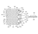
例えば、図20は、特許文献2を基に、円筒型のリチウムイオン二次電池の負極集電体20を展開した図である。かかる負極集電体20は、図20に示すように、巻き始め、或いは、巻き終りに、負極活物質層22が形成されていない未塗工部24が設けられている。金属リチウム26は、負極集電体20の巻き始め或いは巻き終りに設けられた未塗工部24に取り付けられている。このように負極集電体20の巻き始め或いは巻き終りに設けられた未塗工部24に金属リチウム26が取り付けられている場合、金属リチウム26が取り付けられた部位から負極活物質層22の反対側の端部までの距離が長い。負極集電体20が長ければ長くなるほど、金属リチウム26から供給されるリチウムイオンが負極活物質層22全体に均一に拡散し難い。このため、金属リチウム26を取り付けた効果が得られ難い。
For example, FIG. 20 is a diagram in which a negative electrode
さらに、いわゆるハイブリッド車、プラグインハイブリッド車および電気自動車のように、二次電池の出力によって、自動車を駆動させる場合には、電池容量を大きくすることが求められる。電池容量を大きくするためには、帯状の負極集電体と帯状の正極集電体とは、それぞれ長くしたり(例えば、1000mm以上)、負極集電体に対して負極活物質層が形成される面積を広くしたりするとよい。この場合、集電体の巻き始め或いは巻き終りに金属リチウムを取り付けても、金属リチウムから供給されるリチウムイオンが負極活物質層全体に拡散しない。 Further, when the automobile is driven by the output of the secondary battery, such as so-called hybrid cars, plug-in hybrid cars, and electric cars, it is required to increase the battery capacity. In order to increase the battery capacity, the strip-shaped negative electrode current collector and the strip-shaped positive electrode current collector are each elongated (for example, 1000 mm or more), or a negative electrode active material layer is formed on the negative electrode current collector. It is better to increase the area. In this case, even if metallic lithium is attached at the beginning or end of winding of the current collector, lithium ions supplied from the metallic lithium do not diffuse throughout the negative electrode active material layer.
本発明に係るリチウムイオン二次電池は、例えば、帯状の正極集電体と、帯状の負極集電体とを備えている。帯状の正極集電体には、幅方向片側の縁部に沿って未塗工部が設けられている。また、当該未塗工部を除いて正極集電体の両面に正極活物質層が保持されている。帯状の負極集電体には、幅方向片側の縁部に沿って未塗工部が設けられている。また、当該未塗工部を除いて負極集電体の両面に負極活物質層が保持されている。正極活物質層と負極活物質層との間にはセパレータが介在している。 The lithium ion secondary battery according to the present invention includes, for example, a strip-shaped positive electrode current collector and a strip-shaped negative electrode current collector. The strip-shaped positive electrode current collector is provided with an uncoated portion along an edge on one side in the width direction. Moreover, the positive electrode active material layer is hold | maintained on both surfaces of the positive electrode electrical power collector except the said uncoated part. The strip-shaped negative electrode current collector is provided with an uncoated portion along an edge on one side in the width direction. Moreover, the negative electrode active material layer is hold | maintained on both surfaces of the negative electrode collector except the said uncoated part. A separator is interposed between the positive electrode active material layer and the negative electrode active material layer.
負極集電体の未塗工部は、正極集電体の幅方向において正極集電体の未塗工部とは反対側に配置されている。また、セパレータを介在させた状態において負極活物質層が正極活物質層を覆うように、負極活物質層と正極活物質層とが重ねられている。さらに正極集電体と負極集電体とが、正極集電体の幅方向に設定された捲回軸周りに捲回されている。そして、このリチウムイオン二次電池では、かかる負極集電体の未塗工部およびその近傍に金属リチウムが取り付けられている。 The uncoated portion of the negative electrode current collector is disposed on the side opposite to the uncoated portion of the positive electrode current collector in the width direction of the positive electrode current collector. In addition, the negative electrode active material layer and the positive electrode active material layer are stacked so that the negative electrode active material layer covers the positive electrode active material layer with the separator interposed. Furthermore, the positive electrode current collector and the negative electrode current collector are wound around a winding axis set in the width direction of the positive electrode current collector. In this lithium ion secondary battery, metallic lithium is attached to the uncoated portion of the negative electrode current collector and the vicinity thereof.
かかるリチウムイオン二次電池によれば、金属リチウムが負極集電体の未塗工部およびその近傍に取り付けられているので、金属リチウムから供給されたリチウムイオンが負極活物質層全体に拡散し易い。このため、リチウムイオン二次電池の充放電サイクル特性が向上する。 According to such a lithium ion secondary battery, since lithium metal is attached to the uncoated portion of the negative electrode current collector and in the vicinity thereof, lithium ions supplied from the metal lithium are likely to diffuse throughout the negative electrode active material layer. . For this reason, the charge / discharge cycle characteristics of the lithium ion secondary battery are improved.
また、リチウムイオン二次電池は、負極集電体の未塗工部は、捲回された状態において中間部分が寄せ集められて負極端子が溶接されていてもよい。この場合、金属リチウムは、未塗工部に取り付けられていてもよい。また、金属リチウムは、未塗工部の近傍において負極端子に取り付けられていてもよい。 Further, in the lithium ion secondary battery, the uncoated portion of the negative electrode current collector may be gathered at the intermediate portion in a wound state and the negative electrode terminal may be welded. In this case, metallic lithium may be attached to the uncoated part. Moreover, metallic lithium may be attached to the negative electrode terminal in the vicinity of the uncoated part.
また、金属リチウムは、負極集電体の未塗工部に、負極集電体の長さ方向に沿って取り付けられていてもよい。さらに、金属リチウムは、細長い帯状の箔であり、負極活物質層の縁に沿って取り付けられているとよい。また、金属リチウムは、負極集電体の長さ方向に沿って間欠的に取り付けられていてもよい。また、金属リチウムは、負極集電体の片面に配置されていてもよいし、負極集電体の両面に配置されていてもよい。 Moreover, metallic lithium may be attached to the uncoated part of the negative electrode current collector along the length direction of the negative electrode current collector. Furthermore, the metallic lithium is an elongated strip-like foil, and is preferably attached along the edge of the negative electrode active material layer. Moreover, metallic lithium may be intermittently attached along the length direction of the negative electrode current collector. Moreover, metallic lithium may be arrange | positioned at the single side | surface of the negative electrode collector, and may be arrange | positioned at both surfaces of the negative electrode collector.
また、金属リチウムは、好適には負極の可逆容量の10%以上30%以下であるとよい。これにより、リチウムイオン二次電池の出力は、低い充電状態でも高く維持される。 In addition, metallic lithium is preferably 10% to 30% of the reversible capacity of the negative electrode. Thereby, the output of a lithium ion secondary battery is maintained high even in a low charge state.
ここではまず、リチウムイオン二次電池の一構造例を説明する。その後、かかる構造例を適宜参照しつつ、本発明の一実施形態に係るリチウムイオン二次電池を説明する。なお、同じ作用を奏する部材、部位には適宜に同じ符号を付している。また、各図面は模式的に描かれており、必ずしも実物を反映していない。各図面は、一例を示すのみであり、特に言及されない限りにおいて本発明を限定しない。 Here, a structural example of a lithium ion secondary battery will be described first. Thereafter, a lithium ion secondary battery according to an embodiment of the present invention will be described with reference to such structural examples as appropriate. In addition, the same code | symbol is attached | subjected suitably to the member and site | part which show | play the same effect | action. Each drawing is schematically drawn and does not necessarily reflect the real thing. Each drawing shows an example only and does not limit the present invention unless otherwise specified.
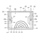
図1は、リチウムイオン二次電池100を示している。このリチウムイオン二次電池100は、図1に示すように、捲回電極体200と電池ケース300とを備えている。図2は、捲回電極体200を示す図である。図3は、図2中のIII−III断面を示している。
FIG. 1 shows a lithium ion
捲回電極体200は、図2に示すように、正極シート220、負極シート240およびセパレータ262、264を有している。正極シート220、負極シート240およびセパレータ262、264は、それぞれ帯状のシート材である。
As shown in FIG. 2, the
≪正極シート220≫
正極シート220は、帯状の正極集電体221と正極活物質層223とを備えている。正極集電体221には、正極に適する金属箔が好適に使用され得る。正極集電体221としては、例えば、所定の幅を有し、厚さが凡そ15μmの帯状のアルミニウム箔を用いることができる。正極集電体221の幅方向片側の縁部に沿って未塗工部222が設定されている。図示例では、正極活物質層223は、図3に示すように、正極集電体221に設定された未塗工部222を除いて、正極集電体221の両面に保持されている。正極活物質層223には、正極活物質が含まれている。正極活物質層223は、正極活物質を含む正極合剤を正極集電体221に塗工することによって形成されている。
≪
The
≪正極活物質層223および正極活物質粒子610≫
ここで、図4は、正極シート220の断面図である。なお、図4において、正極活物質層223の構造が明確になるように、正極活物質層223中の正極活物質粒子610と導電材620とバインダ630とを大きく模式的に表している。正極活物質層223には、図4に示すように、正極活物質粒子610と導電材620とバインダ630が含まれている。
<< Positive Electrode
Here, FIG. 4 is a cross-sectional view of the
正極活物質粒子610には、リチウムイオン二次電池の正極活物質として用いることができる物質を使用することができる。正極活物質の例を挙げると、LiNiCoMnO2(リチウムニッケルコバルトマンガン複合酸化物)、LiNiO2(ニッケル酸リチウム)、LiCoO2(コバルト酸リチウム)、LiMn2O4(マンガン酸リチウム)、LiFePO4(リン酸鉄リチウム)などのリチウム遷移金属酸化物が挙げられる。ここで、LiMn2O4は、例えば、スピネル構造を有している。また、LiNiO2或いはLiCoO2は層状の岩塩構造を有している。また、LiFePO4は、例えば、オリビン構造を有している。オリビン構造のLiFePO4には、例えば、ナノメートルオーダーの粒子がある。また、オリビン構造のLiFePO4は、さらにカーボン膜で被覆することができる。
As the positive electrode
≪導電材620≫
導電材620としては、例えば、カーボン粉末、カーボンファイバーなどのカーボン材料が例示される。このような導電材から選択される一種を単独で用いてもよく二種以上を併用してもよい。カーボン粉末としては、種々のカーボンブラック(例えば、アセチレンブラック、オイルファーネスブラック、黒鉛化カーボンブラック、カーボンブラック、黒鉛、ケッチェンブラック)、グラファイト粉末などのカーボン粉末を用いることができる。
Examples of the
≪バインダ630≫
また、バインダ630は、正極活物質層223に含まれる正極活物質粒子610と導電材620の各粒子を結着させたり、これらの粒子と正極集電体221とを結着させたりする。かかるバインダ630としては、使用する溶媒に溶解または分散可能なポリマーを用いることができる。例えば、水性溶媒を用いた正極合剤組成物においては、セルロース系ポリマー(カルボキシメチルセルロース(CMC)、ヒドロキシプロピルメチルセルロース(HPMC)など)、フッ素系樹脂(例えば、ポリビニルアルコール(PVA)、ポリテトラフルオロエチレン(PTFE)、テトラフルオロエチレン−ヘキサフルオロプロピレン共重合体(FEP)など)、ゴム類(酢酸ビニル共重合体、スチレンブタジエン共重合体(SBR)、アクリル酸変性SBR樹脂(SBR系ラテックス)など)などの水溶性または水分散性ポリマーを好ましく採用することができる。また、非水溶媒を用いた正極合剤組成物においては、ポリマー(ポリフッ化ビニリデン(PVDF)、ポリ塩化ビニリデン(PVDC)、ポリアクリルニトリル(PAN)など)を好ましく採用することができる。
Further, the
≪増粘剤、溶媒≫
正極活物質層223は、例えば、上述した正極活物質粒子610と導電材620を溶媒にペースト状(スラリ状)に混ぜ合わせた正極合剤を作製し、正極集電体221に塗布し、乾燥させ、圧延することによって形成されている。この際、正極合剤の溶媒としては、水性溶媒および非水溶媒の何れも使用可能である。非水溶媒の好適な例としてN−メチル−2−ピロリドン(NMP)が挙げられる。上記バインダ630として例示したポリマー材料は、バインダとしての機能の他に、正極合剤の増粘剤その他の添加剤としての機能を発揮する目的で使用されることもあり得る。
≪Thickener, solvent≫
The positive electrode
正極合剤全体に占める正極活物質の質量割合は、凡そ50wt%以上(典型的には50〜95wt%)であることが好ましく、通常は凡そ70〜95wt%(例えば75〜90wt%)であることがより好ましい。また、正極合剤全体に占める導電材の割合は、例えば凡そ2〜20wt%とすることができ、通常は凡そ2〜15wt%とすることが好ましい。正極合剤全体に占めるバインダの割合は、例えば、凡そ1〜10wt%とすることができ、通常は凡そ2〜5wt%とすることが好ましい。 The mass ratio of the positive electrode active material in the total positive electrode mixture is preferably about 50 wt% or more (typically 50 to 95 wt%), and usually about 70 to 95 wt% (for example, 75 to 90 wt%). It is more preferable. Moreover, the ratio of the electrically conductive material to the whole positive electrode mixture can be, for example, about 2 to 20 wt%, and is usually preferably about 2 to 15 wt%. The ratio of the binder to the whole positive electrode mixture can be, for example, about 1 to 10 wt%, and is usually preferably about 2 to 5 wt%.
≪負極シート240≫
負極シート240は、図2に示すように、帯状の負極集電体241と、負極活物質層243とを備えている。負極集電体241には、負極に適する金属箔が好適に使用され得る。この負極集電体241には、所定の幅を有し、厚さが凡そ10μmの帯状の銅箔が用いられている。負極集電体241の幅方向片側には、縁部に沿って未塗工部242が設定されている。負極活物質層243は、負極集電体241に設定された未塗工部242を除いて、負極集電体241の両面に形成されている。負極活物質層243は、負極集電体241に保持され、少なくとも負極活物質が含まれている。負極活物質層243は、負極活物質を含む負極合剤が負極集電体241に塗工されている。
<<
As illustrated in FIG. 2, the
≪負極活物質層243≫
図5は、リチウムイオン二次電池100の負極シート240の断面図である。負極活物質層243には、図5に示すように、負極活物質710、増粘剤(図示省略)、バインダ730などが含まれている。図5では、負極活物質層243の構造が明確になるように、負極活物質層243中の負極活物質710とバインダ730とを大きく模式的に表している。
<< Negative Electrode
FIG. 5 is a cross-sectional view of the
≪負極活物質≫
負極活物質710としては、従来からリチウムイオン二次電池に用いられる材料の一種または二種以上を特に限定なく使用することができる。例えば、少なくとも一部にグラファイト構造(層状構造)を含む粒子状の炭素材料(カーボン粒子)が挙げられる。より具体的には、負極活物質は、例えば、天然黒鉛、非晶質の炭素材料でコートした天然黒鉛、黒鉛質(グラファイト)、難黒鉛化炭素質(ハードカーボン)、易黒鉛化炭素質(ソフトカーボン)、または、これらを組み合わせた炭素材料でもよい。なお、ここでは、負極活物質710は、いわゆる鱗片状黒鉛が用いられた場合を図示しているが、負極活物質710は、図示例に限定されない。
≪Negative electrode active material≫
As the negative electrode
≪増粘剤、溶媒≫
負極活物質層243は、例えば、上述した負極活物質710とバインダ730を溶媒にペースト状(スラリ状)に混ぜ合わせた負極合剤を作製し、負極集電体241に塗布し、乾燥させ、圧延することによって形成されている。この際、負極合剤の溶媒としては、水性溶媒および非水溶媒の何れも使用可能である。非水溶媒の好適な例としてN−メチル−2−ピロリドン(NMP)が挙げられる。バインダ730には、上記正極活物質層223(図4参照)のバインダ630として例示したポリマー材料を用いることができる。また、上記正極活物質層223のバインダ630として例示したポリマー材料は、バインダとしての機能の他に、正極合剤の増粘剤その他の添加剤としての機能を発揮する目的で使用されることもあり得る。
≪Thickener, solvent≫
The negative electrode
≪セパレータ262、264≫
セパレータ262、264は、図1または図2に示すように、正極シート220と負極シート240とを隔てる部材である。この例では、セパレータ262、264は、微小な孔を複数有する所定幅の帯状のシート材で構成されている。セパレータ262、264には、例えば、多孔質ポリオレフィン系樹脂で構成された単層構造のセパレータ或いは積層構造のセパレータを用いることができる。この例では、図2および図3に示すように、負極活物質層243の幅b1は、正極活物質層223の幅a1よりも少し広い。さらにセパレータ262、264の幅c1、c2は、負極活物質層243の幅b1よりも少し広い(c1、c2>b1>a1)。
<<
The
なお、図1および図2に示す例では、セパレータ262、264は、シート状の部材で構成されている。セパレータ262、264は、正極活物質層223と負極活物質層243とを絶縁するとともに、電解質の移動を許容する部材であればよい。従って、シート状の部材に限定されない。セパレータ262、264は、シート状の部材に代えて、例えば、正極活物質層223または負極活物質層243の表面に形成された絶縁性を有する粒子の層で構成してもよい。ここで、絶縁性を有する粒子としては、絶縁性を有する無機フィラー(例えば、金属酸化物、金属水酸化物などのフィラー)、或いは、絶縁性を有する樹脂粒子(例えば、ポリエチレン、ポリプロピレンなどの粒子)で構成してもよい。
In the example shown in FIGS. 1 and 2, the
≪電池ケース300≫
また、この例では、電池ケース300は、図1に示すように、いわゆる角型の電池ケースであり、容器本体320と、蓋体340とを備えている。容器本体320は、有底四角筒状を有しており、一側面(上面)が開口した扁平な箱型の容器である。蓋体340は、当該容器本体320の開口(上面の開口)に取り付けられて当該開口を塞ぐ部材である。
In this example, as shown in FIG. 1, the
車載用の二次電池では、車両の燃費を向上させるため、重量エネルギー効率(単位重量当りの電池の容量)を向上させることが望まれる。このため、この実施形態では、電池ケース300を構成する容器本体320と蓋体340は、アルミニウム、アルミニウム合金などの軽量金属が採用されている。これにより重量エネルギー効率を向上させることができる。
In an in-vehicle secondary battery, it is desired to improve the weight energy efficiency (battery capacity per unit weight) in order to improve the fuel efficiency of the vehicle. For this reason, in this embodiment, lightweight metals, such as aluminum and an aluminum alloy, are employ | adopted for the container
電池ケース300は、捲回電極体200を収容する空間として、扁平な矩形の内部空間を有している。また、図1に示すように、電池ケース300の扁平な内部空間は、捲回電極体200よりも横幅が少し広い。この実施形態では、電池ケース300は、有底四角筒状の容器本体320と、容器本体320の開口を塞ぐ蓋体340とを備えている。また、電池ケース300の蓋体340には、電極端子420、440が取り付けられている。電極端子420、440は、電池ケース300(蓋体340)を貫通して電池ケース300の外部に出ている。また、蓋体340には注液孔350と安全弁360とが設けられている。
The
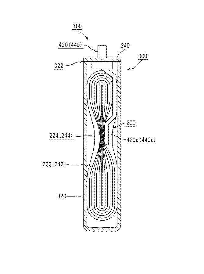
捲回電極体200は、図2に示すように、捲回軸WLに直交する一の方向において扁平に押し曲げられている。図2に示す例では、正極集電体221の未塗工部222と負極集電体241の未塗工部242は、それぞれセパレータ262、264の両側において、らせん状に露出している。図6に示すように、この実施形態では、未塗工部222、242の中間部分224、244を寄せ集め、電極端子420、440の先端部420a、440aに溶接している。この際、それぞれの材質の違いから、電極端子420と正極集電体221の溶接には、例えば、超音波溶接が用いられる。また、電極端子440と負極集電体241の溶接には、例えば、抵抗溶接が用いられる。ここで、図6は、捲回電極体200の未塗工部222(242)の中間部分224(244)と電極端子420(440)との溶接箇所を示す側面図であり、図1のVI−VI断面図である。
As shown in FIG. 2, the
捲回電極体200は、扁平に押し曲げられた状態で、蓋体340に固定された電極端子420、440に取り付けられる。かかる捲回電極体200は、図1に示すように、容器本体320の扁平な内部空間に収容される。容器本体320は、捲回電極体200が収容された後、蓋体340によって塞がれる。蓋体340と容器本体320の合わせ目322(図1参照)は、例えば、レーザ溶接によって溶接されて封止されている。このように、この例では、捲回電極体200は、蓋体340(電池ケース300)に固定された電極端子420、440によって、電池ケース300内に位置決めされている。
The
≪電解液≫
その後、蓋体340に設けられた注液孔350から電池ケース300内に電解液が注入される。電解液は、水を溶媒としていない、いわゆる非水電解液が用いられている。この例では、電解液は、エチレンカーボネートとジエチルカーボネートとの混合溶媒(例えば、体積比1:1程度の混合溶媒)にLiPF6を約1mol/リットルの濃度で含有させた電解液が用いられている。その後、注液孔350に金属製の封止キャップ352を取り付けて(例えば溶接して)電池ケース300を封止する。なお、電解液は、ここで例示された電解液に限定されない。例えば、従来からリチウムイオン二次電池に用いられている非水電解液は適宜に使用することができる。
≪Electrolytic solution≫
Thereafter, an electrolytic solution is injected into the
≪空孔≫
ここで、正極活物質層223は、例えば、正極活物質粒子610と導電材620の粒子間などに、空洞とも称すべき微小な隙間225を有している(図4参照)。かかる正極活物質層223の微小な隙間には電解液(図示省略)が浸み込み得る。また、負極活物質層243は、例えば、負極活物質710の粒子間などに、空洞とも称すべき微小な隙間245を有している(図5参照)。ここでは、かかる隙間225、245(空洞)を適宜に「空孔」と称する。また、捲回電極体200は、図2に示すように、捲回軸WLに沿った両側において、未塗工部222、242が螺旋状に巻かれている。かかる捲回軸WLに沿った両側252、254において、未塗工部222、242の隙間から、電解液が浸み込みうる。このため、リチウムイオン二次電池100の内部では、正極活物質層223と負極活物質層243に電解液が浸み渡っている。
≪Hole≫
Here, the positive electrode
≪ガス抜け経路≫
また、この例では、当該電池ケース300の扁平な内部空間は、扁平に変形した捲回電極体200よりも少し広い。捲回電極体200の両側には、捲回電極体200と電池ケース300との間に隙間310、312が設けられている。当該隙間310、312は、ガス抜け経路になる。例えば、過充電が生じた場合などにおいて、リチウムイオン二次電池100の温度が所定値以上になると、電解液の分解等により発生するガスによって電池ケース300の内圧が上昇する場合がある。この実施形態では、発生したガスは、捲回電極体200の両側における捲回電極体200と電池ケース300との隙間310、312を通して安全弁360の方へ移動し、安全弁360から電池ケース300の外に排気される。
≪Gas escape route≫
In this example, the flat internal space of the
かかるリチウムイオン二次電池100では、正極集電体221と負極集電体241は、電池ケース300を貫通した電極端子420、440を通じて外部の装置に電気的に接続されている。以下、充電時と放電時のリチウムイオン二次電池100の動作を説明する。
In the lithium ion
≪充電時の動作≫
図7は、かかるリチウムイオン二次電池100の充電時の状態を模式的に示している。充電時においては、図7に示すように、リチウムイオン二次電池100の電極端子420、440(図1参照)は、充電器290に接続される。充電器290の作用によって、充電時には、正極活物質層223中の正極活物質からリチウムイオン(Li)が電解液280に放出される。また、正極活物質層223からは電荷が放出される。放出された電荷は、導電材(図示省略)を通じて正極集電体221に送られ、さらに、充電器290を通じて負極シート240へ送られる。また、負極シート240では電荷が蓄えられるとともに、電解液280中のリチウムイオン(Li)が、負極活物質層243中の負極活物質に吸収され、かつ、貯蔵される。
≪Operation when charging≫
FIG. 7 schematically shows the state of the lithium ion
≪放電時の動作≫
図8は、かかるリチウムイオン二次電池100の放電時の状態を模式的に示している。放電時には、図8に示すように、負極シート240から正極シート220に電荷が送られるとともに、負極活物質層243に貯蔵されたリチウムイオンが、電解液280に放出される。また、正極では、正極活物質層223中の正極活物質に電解液280中のリチウムイオンが取り込まれる。
<< Operation during discharge >>
FIG. 8 schematically shows a state of the lithium ion
このようにリチウムイオン二次電池100の充放電において、電解液280を介して、正極活物質層223と負極活物質層243との間でリチウムイオンが行き来する。また、充電時においては、正極活物質から導電材を通じて正極集電体221に電荷が送られる。これに対して、放電時においては、正極集電体221から導電材を通じて正極活物質に電荷が戻される。
Thus, in charging / discharging of the lithium ion
充電時においては、リチウムイオンの移動および電子の移動がスムーズなほど、効率的で急速な充電が可能になると考えられる。放電時においては、リチウムイオンの移動および電子の移動がスムーズなほど、電池の抵抗が低下し、放電量が増加し、電池の出力が向上すると考えられる。 During charging, the smoother the movement of lithium ions and the movement of electrons, the more efficient and rapid charging is considered possible. At the time of discharging, it is considered that the smoother the movement of lithium ions and the movement of electrons, the lower the resistance of the battery, the amount of discharge, and the output of the battery.
≪他の電池形態≫
なお、上記はリチウムイオン二次電池の一例を示すものである。リチウムイオン二次電池は上記形態に限定されない。また、同様に金属箔に電極合剤が塗工された電極シートは、他にも種々の電池形態に用いられる。例えば、他の電池形態として、円筒型電池或いはラミネート型電池などが知られている。円筒型電池は、円筒型の電池ケースに捲回電極体を収容した電池である。また、ラミネート型電池は、正極シートと負極シートとをセパレータを介在させて積層した電池である。
≪Other battery types≫
The above shows an example of a lithium ion secondary battery. The lithium ion secondary battery is not limited to the above form. Similarly, an electrode sheet in which an electrode mixture is applied to a metal foil is used in various other battery forms. For example, as another battery type, a cylindrical battery or a laminate battery is known. A cylindrical battery is a battery in which a wound electrode body is accommodated in a cylindrical battery case. A laminate type battery is a battery in which a positive electrode sheet and a negative electrode sheet are stacked with a separator interposed therebetween.
以下、本発明の一実施形態に係るリチウムイオン二次電池を説明する。 Hereinafter, a lithium ion secondary battery according to an embodiment of the present invention will be described.
≪リチウムイオン二次電池100A≫
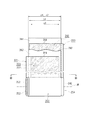
図9は、本発明の一実施形態に係るリチウムイオン二次電池100Aを示している。図10は、リチウムイオン二次電池100Aの捲回電極体200Aを展開した展開図である。また、図11は、当該リチウムイオン二次電池100Aの負極シート240Aを示す図である。リチウムイオン二次電池100Aの基本的な構造は、図1から図8に示すリチウムイオン二次電池100と同じであり、ここでは重複した説明を省略する。また、適宜に上述したリチウムイオン二次電池100の図を参照して説明する。
≪Lithium ion
FIG. 9 shows a lithium ion
≪金属リチウム120≫
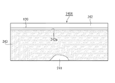
図9に示すリチウムイオン二次電池100Aでは、負極シート240Aは、負極集電体241の未塗工部242に金属リチウム120が取り付けられている。この実施形態では、図10および図11に示すように、負極集電体241の長さ方向に沿って金属リチウム120が取り付けられている。より具体的には、図11に示すように、金属リチウム120は、細長い帯状の箔(この実施形態では、幅2mm程度の帯状の箔)であり、負極活物質層243の縁243aに沿って取り付けられている。この際、負極集電体241の未塗工部242に金属リチウム120を貼り付ける方法は、特に限定されない。例えば、エンボス処理により、箔状の金属リチウム120と、負極集電体241の未塗工部242とを圧着させるとよい。これにより、接着剤やビスなどを用いずに、箔状の金属リチウム120を負極集電体241の未塗工部242に貼り付けることができる。
In the lithium ion
この実施形態では、負極活物質として炭素材料が用いられている。この試験用電池では、捲回電極体200Aを電池ケース300に収容し、電解液を入れる。この際、初期段階において、負極活物質として炭素材料の電位は3V程度であり、金属リチウム120の電位は0Vである。このため、初期段階でリチウムイオン二次電池100Aを放置すると、負極活物質層243と金属リチウム120との電位差により、金属リチウム120が溶出し、さらに金属リチウム120から溶出したリチウムイオンが負極活物質層243に浸入していく。このため、金属リチウム120から供給されたリチウムイオンが負極活物質層243全体に拡散し易く、リチウムイオン二次電池100Aの充放電サイクル特性が向上する。
In this embodiment, a carbon material is used as the negative electrode active material. In this test battery, the
この場合、電解液を入れた後、10時間程度放置することによって、金属リチウム120から供給されたリチウムイオンを、負極活物質層243に十分に浸入させることができる。さらに、金属リチウム120から供給されたリチウムイオンを、負極活物質層243に十分に浸入していると、電池電圧は概ね2.0V以上になる。このため、捲回電極体200を電池ケース300に収容し、電解液を入れた後、例えば、10時間程度放置し、かつ、電池電圧が2.0V以上になった後で初期充電を行なうとよい。
In this case, the lithium ion supplied from the
≪金属リチウム120の配置≫
また、この実施形態では、リチウムイオン二次電池100Aは、図9に示すように、帯状の負極集電体241の幅方向片側の縁部に沿って未塗工部242が設けられている。さらに、金属リチウム120は、図11に示すように、当該負極集電体241の未塗工部242に、負極集電体241の長さ方向に沿って取り付けられている。
≪Arrangement of
In this embodiment, as shown in FIG. 9, in the lithium ion
この場合、金属リチウム120から供給されるリチウムイオンは、負極活物質層243の全体にわたって拡散するためには、例えば、負極活物質層243を幅方向に横断するとよい。この際、金属リチウムから供給されるリチウムイオンが負極活物質層243の全体にわたって拡散するのに要する、リチウムイオンの移動距離が総じて短い。このように、リチウムイオン二次電池100Aは、負極活物質層243全体にリチウムイオンが拡散しやすく、負極活物質層243全体として金属リチウム120を取り付けた効果が得られやすい。
In this case, in order for the lithium ions supplied from the
リチウムイオン二次電池100Aは、特に、充電状態(SOC:state of charge)が低い場合における出力が向上する。図12は、本発明の一実施形態に係るリチウムイオン二次電池100Aの出力特性を、金属リチウム120が取り付けられていない場合と比べた典型的なグラフである。図12中、Aは本発明の一実施形態に係るリチウムイオン二次電池100Aの出力特性(充電状態−電圧)を示しており、Bは金属リチウム120が取り付けられていない場合の出力特性(充電状態−電圧)を示している。すなわち、Bで示されたリチウムイオン二次電池は、金属リチウム120が取り付けられていない点を除いて、Aで示された本発明の一実施形態に係るリチウムイオン二次電池100Aと同じ構成である。
The output of the lithium ion
図12中のBで示すように、金属リチウム120が取り付けられていない場合には、SOCが低下すると(図示例では、SOCが10%程度に低下すると)、出力(電圧)が急激に低下する。これに対して、金属リチウム120が取り付けられているリチウムイオン二次電池100Aでは、SOCが5%程度から出力(電圧)が急激に低下する。このように、金属リチウム120が取り付けられることによって、リチウムイオン二次電池100Aは低い充電状態で出力を高く維持することができる。
As indicated by B in FIG. 12, when the
さらに、この実施形態では、金属リチウム120は、図11に示すように、細長い帯状の箔(この実施形態では、幅3mm程度の帯状の箔)であり、負極活物質層243の縁243aに沿って取り付けられている。当該負極活物質層243の縁243aは、電解液を通じてリチウムイオンが負極活物質層243に浸入する入り口である。この実施形態では、当該負極活物質層243の縁243aに沿って細長い帯状の金属リチウム120が取り付けられているので、金属リチウム120から供給されるリチウムイオンが負極活物質層243に効率よく浸入する。このため、負極活物質層243において金属リチウム120が不足するのをより効果的に防止できる。
Furthermore, in this embodiment, the
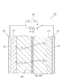
さらに、この実施形態では、負極集電体241の未塗工部242は、図9および図13に示すように、捲回された状態において中間部分244が寄せ集められて負極端子440に溶接されている。図13は、寄せ集められて溶接された負極集電体241の未塗工部242の中間部分244を示す断面図(図9のXIII−XIII断面)である。なお、図示の便宜上、図13は特に簡略的に図示している。この実施形態では、図13に示すように、金属リチウム120は、細長い帯状の箔であり、負極活物質層243の縁243aに沿って取り付けられている。
Further, in this embodiment, the
このリチウムイオン二次電池100Aでは、帯状の負極集電体241の幅方向片側の縁部に沿って未塗工部242が設けられている。そして、未塗工部242を除いて負極集電体241の両面に負極活物質層243が保持されている。かかる負極集電体241は、図9に示すように、捲回された状態において中間部分244が寄せ集められて溶接されている。この場合、図13に示すように、負極活物質層243の縁243aの近傍には、若干の隙間がある。この実施形態では、かかる隙間に箔状の金属リチウム120を収めている。
In this lithium ion
このように、リチウムイオン二次電池100Aでは、負極集電体241は捲回された状態において、未塗工部242の中間部分244が寄せ集められて溶接されている。この場合、図13に示すように、負極活物質層243が配置された領域は、図13に示すように、捲回された負極集電体241によって仕切られている。この実施形態では、負極集電体241によって仕切られた各空間において、負極活物質層243の縁243aに細長い箔状の金属リチウム120が取り付けられている。このため、金属リチウム120から供給されるリチウムイオンがより効率よく負極活物質層243に浸入する。
Thus, in the lithium ion
この実施形態では、図13に示すように、金属リチウム120は、負極集電体241の片面に配置されている。ここでは、負極集電体241や負極活物質層243に対する、金属リチウム120の厚さや、捲回工程の作業性を考慮して、箔状の金属リチウム120を負極集電体241の片面に配置している。この場合、金属リチウム120を負極集電体241の片面にのみ配置すればよいので、金属リチウム120の取り付けが容易である。
In this embodiment, as shown in FIG. 13, the
また、図14に示すように、金属リチウム120は、負極集電体241の両面に配置してもよい。この場合でも、負極集電体241の未塗工部242の中間部分244が寄せ集められて溶接された構成において、負極集電体241で仕切られる各空間に金属リチウム120が配置することができる。また、この実施形態では、負極集電体241の両面に負極活物質層243があり、負極集電体241の両面の負極活物質層243により均一に金属リチウム120を供給することができる。
Further, as shown in FIG. 14, the
この実施形態では、金属リチウム120は、負極集電体241の長さ方向に沿って取り付けられているが、負極集電体241は捲回され、さらに扁平に押し曲げられる。図15に示すように、金属リチウム120は、負極集電体241の長さ方向に沿って間欠的に取り付けられていてもよい。かかる形態では、例えば、2mm〜15mm程度の長さの箔状の金属リチウム120が、間隔を開けて負極集電体241に取り付けられていてもよい。これにより、金属リチウム120が長さ方向に取り付けられた状態での負極集電体241の可撓性を確保することができる。
In this embodiment, the
以上、金属リチウム120から供給されるリチウムイオンが負極活物質層243へ拡散するのに、特に適した金属リチウム120の配置例を挙げた。金属リチウム120の配置は、上記に限定されない。
As described above, the arrangement example of the
金属リチウム120は、例えば、図16に示すように、負極端子440に取り付けてもよい。また、図17に示すように、金属リチウム120は、捲回された負極集電体241の最外周の未塗工部242に取り付けてもよい。なお、図17に示す形態では、負極端子440の構造は、図9および図16の形態と異なる。このような場合でも、金属リチウム120は、初期段階における負極活物質として炭素材料と、金属リチウム120との電位差によって、金属リチウム120から溶出したリチウムイオンが負極活物質層243に浸入していく。このため、金属リチウム120から供給されたリチウムイオンが負極活物質層243全体に拡散し易く、リチウムイオン二次電池100Aの充放電サイクル特性が向上する。
For example, the
≪金属リチウム120の量≫
また、取り付けられる金属リチウム120は、負極の可逆容量の10%以上30%以下であるとよい。ここで、「負極の可逆容量」は、リチウムイオン二次電池100に可逆的に充放電できる電気量が相当する。すなわち、負極活物質として炭素材料が用いられている場合、初期充電によって負極に挿入されたリチウムの一部が、実質的に負極に固定され、負極から放出されない。このため、初めて充電(初期充電)を行うと、当該充電量に見合った量を放電できない事象が生じ得る。「負極の可逆容量」は、実質的にリチウムイオン二次電池100に充放電できる電気量である。「負極の可逆容量」は、例えば、負極を金属リチウムの対極として、金属リチウムの電位(0V)まで充電し、約1.5V(Li/Li+)まで放電した時の放電容量を測定することによって定めるとよい。
≪Amount of
Moreover, the
例えば、負極の可逆容量が6Ahである場合には、負極の可逆容量の20%は1.2Ahであり、当該1.2Ahに相当する金属リチウム120を負極集電体241の未塗工部242に取り付けるとよい。ここで、1.2Ahに相当する金属リチウム120は、理論的には凡そ311mgである。
For example, when the reversible capacity of the negative electrode is 6 Ah, 20% of the reversible capacity of the negative electrode is 1.2 Ah, and the
ここでは、試験用電池を用意し、金属リチウム120の量を変えて、リチウムイオン二次電池100Aの特性を調べた。
Here, a test battery was prepared, and the characteristics of the lithium ion
≪試験用電池≫
試験用電池の基本構成は、図16に示す形態であり、ここでは、負極端子440に金属リチウム120が取り付けている。
≪Test battery≫
The basic configuration of the test battery is the form shown in FIG. 16, and here,
ここで、試験用電池では、凡そ15μm厚、幅114.0mm、長さ3000mmのアルミニウム箔からなる正極集電体221の両面に正極活物質層223が形成されている。正極活物質層223に含まれる正極活物質はLiNiCoAlO2の複合酸化物、導電材はアセチレンブラック(AB)、結着剤はポリフッ化ビニリデン(PVDF)である。正極活物質と導電材と結着剤とは、重量比において、正極活物質:導電材:結着剤=100:5:5とした。正極シート220は、正極集電体221に正極活物質層223が塗工された部分の厚さが圧延後において凡そ100μmであり、正極集電体221の両面に凡そ42〜43μmの厚さの正極活物質層223が形成されている。また、正極集電体221に正極活物質層223が塗工された幅は、98.0mmである。
Here, in the test battery, the positive electrode active material layers 223 are formed on both surfaces of the positive electrode
また、試験用電池では、凡そ20μm厚、幅119.0mm、長さ3300mmの銅箔からなる負極集電体241の両面に負極活物質層243が形成されている。負極活物質層243に含まれる負極活物質は黒鉛、結着剤はポリフッ化ビニリデン(PVDF)である。負極活物質と結着剤とは、重量比において、負極活物質:結着剤=100:7とした。負極シート240は、負極集電体241に負極活物質層243が塗工された部分の厚さが圧延後において凡そ120μmであり、負極集電体241の両面に凡そ50μmの厚さの負極活物質層243が形成されている。また、負極集電体241に負極活物質層243が塗工された幅は、103.0mmである。
In the test battery, negative electrode active material layers 243 are formed on both surfaces of a negative electrode
また、セパレータ262、264には、ポリエチレン(PE)の両側をポリプロピレン(PP)で挟んだ3層構造(PP/PE/PP)のセパレータが用いられている。当該セパレータ262、264の厚さは、20μmである。また、電解液には、エチレンカーボネート(EC)と、ジメチルカーボネート(DMC)と、エチルメチルカーボネート(EMC)とを、EC:DMC:EMC=3:4:3の体積比で混合した混合溶媒に、LiPF6を約1mol/リットルの濃度で含有させた電解液を用いた。電解液は、負極端子440に金属リチウム120が取り付けられた状態で注液されている。
Further, as the
≪サンプル≫
ここでは、上述した試験用電池について、負極端子440に取り付けた金属リチウム120の量を変えた複数のサンプルを用意して、負極近傍に取り付けるのに適当な金属リチウム120の量を調べた。
≪Sample≫
Here, with respect to the test battery described above, a plurality of samples in which the amount of the
ここでは、各サンプルに対して、所定のコンディショニング工程を行い、SOC20%の充電状態における出力特性を測定した。
Here, the predetermined conditioning process was performed with respect to each sample, and the output characteristics in the
≪コンディショニング≫
次に、上記のように構築した試験用電池について、電解液を注入した後で、10時間程度放置し、電池電圧が2.0V以上になってから初期充電を行なった。コンディショニング工程は、次の手順1、2によって行なわれる。
手順1:1Cの定電流充電にて4.1Vに到達した後、5分間休止する。
手順2:手順1の後、定電圧充電にて1.5時間充電し、5分間休止する。
<< conditioning >>
Next, the test battery constructed as described above was poured for about 10 hours after injecting the electrolytic solution, and was initially charged after the battery voltage became 2.0 V or higher. The conditioning process is performed by the following procedures 1 and 2.
Procedure 1: After reaching 4.1 V with a constant current charge of 1 C, pause for 5 minutes.
Procedure 2: After Procedure 1, charge for 1.5 hours by constant voltage charging and rest for 5 minutes.
≪定格容量の測定≫
次に、定格容量は、上記コンディショニング工程の後、試験用電池について、温度25℃、3.0Vから4.1Vの電圧範囲で、次の手順1〜3によって測定される。
手順1:1Cの定電流放電によって3.0Vに到達後、定電圧放電にて2時間放電し、その後、10秒間休止する。
手順2:1Cの定電流充電によって4.1Vに到達後、定電圧充電にて2.5時間充電し、その後、10秒間休止する。
手順3:0.5Cの定電流放電によって3.0Vに到達後、定電圧放電にて2時間放電し、その後、10秒間停止する。
定格容量:手順3における定電流放電から定電圧放電に至る放電における放電容量(CCCV放電容量)を定格容量とする。この試験用電池では、定格容量が凡そ4.6Ahになる。
≪Measurement of rated capacity≫
Next, the rated capacity is measured by the following procedures 1 to 3 at a temperature of 25 ° C. and a voltage range of 3.0 V to 4.1 V for the test battery after the conditioning step.
Procedure 1: After reaching 3.0V by constant current discharge of 1C, discharge by constant voltage discharge for 2 hours, and then rest for 10 seconds.
Procedure 2: After reaching 4.1 V by constant current charging at 1 C, charge for 2.5 hours by constant voltage charging, and then rest for 10 seconds.
Procedure 3: After reaching 3.0 V by constant current discharge of 0.5 C, discharge at constant voltage discharge for 2 hours, and then stop for 10 seconds.
Rated capacity: The discharge capacity (CCCV discharge capacity) in the discharge from the constant current discharge to the constant voltage discharge in the procedure 3 is defined as the rated capacity. In this test battery, the rated capacity is about 4.6 Ah.
≪SOC調整≫
SOC調整は、次の1、2の手順によって調整される。ここで、SOC調整は、上記コンディショニング工程および定格容量の測定の後で行なうとよい。また、ここでは、温度による影響を一定にするため、25℃の温度環境下でSOC調整を行なっている。
手順1:3Vから1Cの定電流で充電し、定格容量の凡そ20%の充電状態(SOC20%)にする。
手順2:手順1の後、2.5時間、定電圧充電する。
これにより、試験用電池は、所定の充電状態に調整することができる。
≪SOC adjustment≫
The SOC adjustment is performed by the following procedures 1 and 2. Here, the SOC adjustment may be performed after the conditioning process and the measurement of the rated capacity. Here, in order to make the influence of temperature constant, SOC adjustment is performed in a temperature environment of 25 ° C.
Procedure 1: Charging at a constant current of 3V to 1C to obtain a charged state (
Procedure 2: After procedure 1, charge at constant voltage for 2.5 hours.
Thereby, the test battery can be adjusted to a predetermined state of charge.
≪SOC20%での出力特性≫
ここでは、試験用電池をSOC20%での出力特性で評価した。SOC20%での出力特性は、以下の通りに、測定した。
≪Output characteristics at 20% SOC≫
Here, the test battery was evaluated by the output characteristics at
SOC20%に調整した試験用電池に対して、SOC20%に調整した試験用電池を所定のパルス電流で放電する。この際、パルス電流を0.3C、1C、3C、5C、10Cと順に階段状に増加させ、それぞれ放電開始から10秒後の正極端子420と負極端子440の端子間の電圧(端子電圧)を測定した。そして、パルス電流を0.3C、1C、3C、5C、10Cにした場合に測定された端子電圧を基に、試験用電池の放電終止電圧である3.0Vに外挿した電流値CAを最小2乗法によって直線近似して求めた。ここで、試験用電池の出力CW1は、CW1=CA(A)×3.0(V)で求められる。かかる出力CW1を、SOC20%での出力特性とした。
The test battery adjusted to
表1は、サンプル1〜5について、SOC20%での出力特性を示している。ここで、SOC20%での出力特性が大きいほど、試験用電池は、低い充電状態でも出力が維持されると考えられる。
この場合、サンプル1は、負極端子440に取り付けた金属リチウム120を負極の可逆容量に対する20%相当の量にした。サンプル1では、SOC20%での出力特性は550Wであった。
In this case, in Sample 1, the amount of
また、サンプル2は、負極端子440に取り付けた金属リチウム120を負極の可逆容量に対する10%相当の量にした。サンプル2では、SOC20%での出力特性は500Wであった。
In Sample 2, the amount of
また、サンプル3は、負極端子440に取り付けた金属リチウム120を負極の可逆容量に対する30%相当の量にした。サンプル3では、SOC20%での出力特性は520Wであった。
In Sample 3, the amount of
また、サンプル4は、負極端子440に取り付けた金属リチウム120を負極の可逆容量に対する40%相当の量にした。サンプル4では、SOC20%での出力特性は350Wであった。
In Sample 4, the amount of
また、サンプル5は、負極端子440に取り付けた金属リチウム120を負極の可逆容量に対する5%相当の量にした。サンプル5では、SOC20%での出力特性は300Wであった。
In Sample 5, the amount of
ここで、負極端子440に取り付けた金属リチウム120が負極の可逆容量に対して5%相当程度の量では、金属リチウム120の量が不十分であることが考えられる。また、負極端子440に取り付けた金属リチウム120が負極の可逆容量に対して40%相当程度の量では、負極端子440に取り付けた金属リチウム120の一部が負極活物質層243に浸入せずに残留していることが考えられる。金属リチウム120の一部が負極活物質層243に浸入せずに残留していると、例えば、残留した金属リチウム120が電解液と副反応を起こして、試験用電池の内部抵抗が大きくなり、SOC20%での出力特性が低下する。
Here, if the amount of
このように、負極近傍に取り付ける金属リチウム120は、負極の可逆容量に対して10%以上30%以下程度の量であれば、試験用電池のSOC20%での出力特性は、概ね500W以上であり、金属リチウム120を取り付けた効果がより適切に得られると考えられる。このため、上述したリチウムイオン二次電池100Aにおいて、負極集電体241の未塗工部242およびその近傍に取り付けられる金属リチウムは、負極の可逆容量に対して10%以上30%以下程度の量が望ましい。これにより、リチウムイオン二次電池100Aの出力は、低い充電状態でも高く維持される。なお、金属リチウム120は、より好ましくは負極の可逆容量の12%以上、さらに好ましくは15%以上であるとよい。また、金属リチウム120は、より好ましくは負極の可逆容量の28%以下、さらに好ましくは25%以下であるとよい。
Thus, if the amount of
以上、説明したように、本発明の一実施形態に係るリチウムイオン二次電池100Aは、例えば、図9に示すように、帯状の正極集電体221と、帯状の負極集電体241とを備えている。帯状の正極集電体221には、幅方向片側の縁部に沿って未塗工部222が設けられている。また、当該未塗工部222を除いて正極集電体221の両面に正極活物質層223が保持されている。帯状の負極集電体241には、幅方向片側の縁部に沿って未塗工部242が設けられている。また、当該未塗工部242を除いて負極集電体241の両面に負極活物質層243が保持されている。正極活物質層223と負極活物質層243との間にはセパレータ262、264が介在している。
As described above, a lithium ion
負極集電体241の未塗工部242は、正極集電体221の幅方向において正極集電体221の未塗工部222とは反対側に配置されている。また、セパレータ262、264を介在させた状態において負極活物質層243が正極活物質層223を覆うように、負極活物質層243と正極活物質層223とが重ねられている。さらに正極集電体221と負極集電体241とが、正極集電体221の幅方向に設定された捲回軸WL周りに捲回されている。このリチウムイオン二次電池100Aでは、かかる負極集電体241の未塗工部242およびその近傍に金属リチウム120が取り付けられている。
The
かかるリチウムイオン二次電池100Aによれば、金属リチウム120が負極集電体241の未塗工部242およびその近傍に取り付けられているので、金属リチウム120から供給されたリチウムイオンが負極活物質層243全体に拡散し易い。このため、リチウムイオン二次電池100Aの充放電サイクル特性が向上する。
According to the lithium ion
また、リチウムイオン二次電池100Aは、図9に示すように、負極集電体241の未塗工部242は、捲回された状態において中間部分244が寄せ集められて負極端子440が溶接されていてもよい。この場合、金属リチウム120は、図9に示すように、未塗工部242に取り付けられていてもよい。また、金属リチウム120は、図16に示すように、未塗工部242の近傍において負極端子440に取り付けられていてもよい。負極端子440に金属リチウム120を取り付ける場合には、当然ではあるが、金属リチウム120は電池ケース300内において負極端子440に取り付けられているとよい。
In addition, as shown in FIG. 9, in the lithium ion
また、金属リチウム120は、図9から図11に示すように、負極集電体241の未塗工部242に、負極集電体241の長さ方向に沿って取り付けられていてもよい。この場合、金属リチウム120から供給されるリチウムイオンは、負極活物質層243の全体にわたって拡散するのに、例えば、負極活物質層243を幅方向に横断するとよい。このため、リチウムイオン二次電池100Aは、負極活物質層243全体にリチウムイオンが拡散しやすく、負極活物質層243全体として金属リチウム120を取り付けた効果が得られやすい。
Further, as shown in FIGS. 9 to 11, the
さらに、金属リチウム120は、図11に示すように、細長い帯状の箔であり、負極活物質層243の縁243aに沿って取り付けられているとよい。当該負極活物質層243の縁243aは、電解液を通じてリチウムイオンが負極活物質層243に浸入する入り口である。この実施形態では、当該負極活物質層243の縁243aに沿って細長い帯状の金属リチウム120が取り付けられているので、金属リチウム120から供給されるリチウムイオンが負極活物質層243に効率よく浸入する。このため、負極活物質層243において金属リチウム120が不足するのをより効果的に防止できる。
Furthermore, as shown in FIG. 11, the
また、金属リチウム120は、図15に示すように、負極集電体241の長さ方向に沿って間欠的に取り付けられていてもよい。これにより、金属リチウム120が長さ方向に取り付けられた状態での負極集電体241の可撓性を確保することができる。
Moreover, the
また、金属リチウム120は、負極集電体241の片面に配置されていてもよいし、負極集電体241の両面に配置されていてもよい。
Further, the
また、金属リチウム120は、負極の可逆容量の10%以上30%以下であるとよい。これにより、リチウムイオン二次電池100Aの出力は、低い充電状態でも高く維持される。
Further, the
以上、本発明の一実施形態に係るリチウムイオン二次電池を説明した。なお、本発明は、特に言及されない限りにおいて、上述した何れの実施形態にも限定されない。 In the above, the lithium ion secondary battery which concerns on one Embodiment of this invention was demonstrated. Note that the present invention is not limited to any of the above-described embodiments unless otherwise specified.
例えば、上述した実施形態では、扁平に押し曲げた捲回電極体200を角型の電池ケース300に収容したリチウムイオン二次電池100Aを例示した。扁平に押し曲げた捲回電極体200を軟らかい容器に収容した、いわゆるラミネート型の電池を構成してもよい。
For example, in the above-described embodiment, the lithium ion
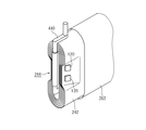
図18は、ラミネート型のリチウムイオン二次電池100Bを示している。ラミネート型の電池の容器300B(外装材)は、2点鎖線で示されており、例えば、アルミニウム製のラミネートフィルムを用いるとよい。捲回電極体200Bは、図9に示すリチウムイオン二次電池100Aの捲回電極体200Aと概ね同じ構造を有しており、同じ作用を奏する部材、部位には同じ符号を付している。
FIG. 18 shows a laminate-type lithium ion
この実施形態では、捲回電極体200Bの捲回軸WLに沿って、一方に正極集電体221の未塗工部222B、他方に負極集電体241の未塗工部242Bがセパレータ262、264からはみ出ている。そして、当該はみ出た部位において、正極集電体221の未塗工部222Bの中間部分224Bが寄せ集められており、当該中間部分224Bに正極端子420Bが取り付けられている。同様に、負極集電体241の未塗工部242Bの中間部分244Bが寄せ集められており、当該中間部分244Bに負極端子440Bが取り付けられている。
In this embodiment, along the winding axis WL of the
このように、本発明は、ラミネート型の電池として構成してもよく、この場合でも、かかる負極集電体241の未塗工部242Bおよびその近傍に金属リチウム120が取り付けられているとよい。これにより、金属リチウム120から供給されたリチウムイオンが負極活物質層243全体に拡散し、リチウムイオン二次電池100Bの充放電サイクル特性、特に低い充電状態におけるリチウムイオン二次電池100Bの出力特性が向上する。
As described above, the present invention may be configured as a laminate-type battery. In this case as well, the
また、上述したように、本発明は、特に低い充電状態におけるリチウムイオン二次電池の出力特性向上に寄与する。このため、本発明に係るリチウムイオン二次電池は、特に、低い充電状態における出力特性について要求されるレベルが高いハイブリッド車(特に、プラグインハイブリッド車)若しくは電気自動車の駆動用電池など車両駆動電源用の二次電池に好適である。 Further, as described above, the present invention contributes to the improvement of the output characteristics of the lithium ion secondary battery in a particularly low charge state. For this reason, the lithium ion secondary battery according to the present invention is a vehicle drive power source such as a hybrid vehicle (particularly, a plug-in hybrid vehicle) or a drive battery for an electric vehicle, which requires a high level of output characteristics particularly in a low charge state. It is suitable for a secondary battery.
この場合、本発明の一実施形態に係るリチウムイオン二次電池は、例えば、図19に示すように、二次電池の複数個を接続して組み合わせた組電池の形態で、自動車などの車両1のモータ(電動機)を駆動させる車両駆動用電池1000として好適に利用され得る。特に、本発明に係るリチウムイオン二次電池は、低い充電量でも安定して高い出力を発揮することができ、より低い充電量での使用に耐えうる。このため、電池を効率よく使用することができるとともに、容量について要求されるレベルが高い場合でも、使用する電池の数を少なくでき、コストダウンを図ることができる。本発明の一実施形態に係るリチウムイオン二次電池は、例えば、ハイブリッド車(特に、プラグインハイブリッド車)若しくは電気自動車の駆動用電池として、例えば、定格容量が3.0Ah以上のリチウムイオン二次電池に好適である。
In this case, the lithium ion secondary battery according to an embodiment of the present invention is, for example, in the form of an assembled battery in which a plurality of secondary batteries are connected and combined as shown in FIG. It can be suitably used as a
1 車両
100、100A、100B リチウムイオン二次電池
120 金属リチウム
200、200A、200B 捲回電極体
220 正極シート
221 正極集電体
222、222B 未塗工部
223 正極活物質層
224、224B 中間部分
225 隙間
240、240A 負極シート
241 負極集電体
242、242B 未塗工部
243 負極活物質層
243a 負極活物質層の縁
244、244B 中間部分
245 隙間
252、254 捲回電極体の捲回軸に沿った両側
262、264 セパレータ
280 電解液
290 充電器
300 電池ケース
300B 容器(外装材、ラミネートフィルム)
310、312 隙間
320 容器本体
322 蓋体と容器本体の合わせ目
340 蓋体
350 注液孔
352 封止キャップ
360 安全弁
420、420B 正極端子(電極端子)
420a 正極端子(電極端子)の先端部
440、440B 負極端子(電極端子)
440a 負極端子(電極端子)の先端部
610 正極活物質粒子
620 導電材
630 バインダ
710 負極活物質
730 バインダ
1000 車両駆動用電池
WL 捲回軸
1
310, 312
Claims (9)
前記正極集電体の幅方向片側の縁部に沿って設けられた未塗工部を除いて前記正極集電体の両面に保持された、正極活物質を含む正極活物質層と、
帯状の負極集電体と、
前記負極集電体の幅方向片側の縁部に沿って設けられた未塗工部を除いて前記負極集電体の両面に保持された、負極活物質を含む負極活物質層と、
前記正極活物質層と負極活物質層との間に介在したセパレータと、
を備え、
前記負極集電体の未塗工部は、前記正極集電体の幅方向において前記正極集電体の未塗工部とは反対側に配置され、かつ、前記セパレータを介在させた状態において前記負極活物質層が前記正極活物質層を覆うように、前記負極活物質層と前記正極活物質層とが重ねられ、さらに前記正極集電体と前記負極集電体とが、前記正極集電体の幅方向に設定された捲回軸周りに捲回されており、
前記負極集電体の未塗工部およびその近傍に金属リチウムが取り付けられた、リチウムイオン二次電池。 A belt-like positive electrode current collector;
A positive electrode active material layer containing a positive electrode active material, which is held on both surfaces of the positive electrode current collector except for an uncoated portion provided along an edge on one side in the width direction of the positive electrode current collector;
A strip-shaped negative electrode current collector;
A negative electrode active material layer containing a negative electrode active material, which is held on both surfaces of the negative electrode current collector except for an uncoated portion provided along an edge on one side in the width direction of the negative electrode current collector;
A separator interposed between the positive electrode active material layer and the negative electrode active material layer;
With
The uncoated portion of the negative electrode current collector is disposed on the side opposite to the uncoated portion of the positive electrode current collector in the width direction of the positive electrode current collector, and the separator is interposed in the state where the separator is interposed. The negative electrode active material layer and the positive electrode active material layer are overlapped so that the negative electrode active material layer covers the positive electrode active material layer, and the positive electrode current collector and the negative electrode current collector further include the positive electrode current collector. It is wound around the winding axis set in the width direction of the body,
A lithium ion secondary battery in which metallic lithium is attached to an uncoated portion of the negative electrode current collector and the vicinity thereof.
前記金属リチウムは、前記未塗工部または前記負極端子に取り付けられている、請求項1に記載されたリチウムイオン二次電池。 In the wound state, the uncoated portion of the negative electrode current collector is gathered in the middle portion and the negative electrode terminal is welded,
The lithium ion secondary battery according to claim 1, wherein the metallic lithium is attached to the uncoated portion or the negative electrode terminal.
Priority Applications (1)
| Application Number | Priority Date | Filing Date | Title |
|---|---|---|---|
| JP2011110360A JP2012243455A (en) | 2011-05-17 | 2011-05-17 | Lithium ion secondary battery |
Applications Claiming Priority (1)
| Application Number | Priority Date | Filing Date | Title |
|---|---|---|---|
| JP2011110360A JP2012243455A (en) | 2011-05-17 | 2011-05-17 | Lithium ion secondary battery |
Publications (1)
| Publication Number | Publication Date |
|---|---|
| JP2012243455A true JP2012243455A (en) | 2012-12-10 |
Family
ID=47464979
Family Applications (1)
| Application Number | Title | Priority Date | Filing Date |
|---|---|---|---|
| JP2011110360A Withdrawn JP2012243455A (en) | 2011-05-17 | 2011-05-17 | Lithium ion secondary battery |
Country Status (1)
| Country | Link |
|---|---|
| JP (1) | JP2012243455A (en) |
Cited By (2)
| Publication number | Priority date | Publication date | Assignee | Title |
|---|---|---|---|---|
| CN104766992A (en) * | 2014-01-08 | 2015-07-08 | 丰田自动车株式会社 | Lithium-ion secondary battery and method of manufacturing same |
| JP2017152356A (en) * | 2016-02-23 | 2017-08-31 | 東莞新能源科技有限公司Dongguan Amperex Technology Limited | Charging method for lithium ion battery |
-
2011
- 2011-05-17 JP JP2011110360A patent/JP2012243455A/en not_active Withdrawn
Cited By (4)
| Publication number | Priority date | Publication date | Assignee | Title |
|---|---|---|---|---|
| CN104766992A (en) * | 2014-01-08 | 2015-07-08 | 丰田自动车株式会社 | Lithium-ion secondary battery and method of manufacturing same |
| US9608295B2 (en) | 2014-01-08 | 2017-03-28 | Toyota Jidosha Kabushiki Kaisha | Lithium-ion secondary battery and method of manufacturing the same |
| KR101732242B1 (en) * | 2014-01-08 | 2017-05-02 | 도요타지도샤가부시키가이샤 | Lithium-ion secondary battery and production method thereof |
| JP2017152356A (en) * | 2016-02-23 | 2017-08-31 | 東莞新能源科技有限公司Dongguan Amperex Technology Limited | Charging method for lithium ion battery |
Similar Documents
| Publication | Publication Date | Title |
|---|---|---|
| JP5787196B2 (en) | Lithium ion secondary battery | |
| JP6144626B2 (en) | Lithium ion secondary battery | |
| JP5783425B2 (en) | Method for producing non-aqueous electrolyte secondary battery | |
| JP5924550B2 (en) | Non-aqueous secondary battery | |
| WO2014119368A1 (en) | Method for manufacturing lithium ion secondary battery | |
| WO2013018180A1 (en) | Lithium ion secondary battery | |
| JP5696886B2 (en) | Secondary battery | |
| EP3048661B1 (en) | Nonaqueous electrolyte secondary battery | |
| JP5835614B2 (en) | Non-aqueous secondary battery | |
| JP5725351B2 (en) | Lithium ion secondary battery | |
| JP2014096269A (en) | Nonaqueous secondary battery | |
| JP5787185B2 (en) | Secondary battery | |
| JP5843092B2 (en) | Lithium ion secondary battery | |
| JP2013235795A (en) | Nonaqueous secondary battery | |
| WO2013018181A1 (en) | Lithium ion secondary battery | |
| JP2013243097A (en) | Secondary battery | |
| JP2013171806A (en) | Secondary battery | |
| JP6120113B2 (en) | Lithium ion secondary battery | |
| JP2013137955A (en) | Nonaqueous secondary battery | |
| JP2015153535A (en) | Nonaqueous electrolyte secondary battery and method for manufacturing the same | |
| JP2012243455A (en) | Lithium ion secondary battery | |
| JP7054440B2 (en) | Secondary battery | |
| JP6731155B2 (en) | Non-aqueous electrolyte secondary battery | |
| JP5783415B2 (en) | Lithium ion secondary battery | |
| JP5854267B2 (en) | Non-aqueous secondary battery |
Legal Events
| Date | Code | Title | Description |
|---|---|---|---|
| A300 | Application deemed to be withdrawn because no request for examination was validly filed |
Free format text: JAPANESE INTERMEDIATE CODE: A300 Effective date: 20140805 |