JP2012243436A - Photoelectric conversion element, method for manufacturing the same, and electronic device - Google Patents
Photoelectric conversion element, method for manufacturing the same, and electronic device Download PDFInfo
- Publication number
- JP2012243436A JP2012243436A JP2011110059A JP2011110059A JP2012243436A JP 2012243436 A JP2012243436 A JP 2012243436A JP 2011110059 A JP2011110059 A JP 2011110059A JP 2011110059 A JP2011110059 A JP 2011110059A JP 2012243436 A JP2012243436 A JP 2012243436A
- Authority
- JP
- Japan
- Prior art keywords
- photoelectric conversion
- conversion element
- dye
- additive
- porous electrode
- Prior art date
- Legal status (The legal status is an assumption and is not a legal conclusion. Google has not performed a legal analysis and makes no representation as to the accuracy of the status listed.)
- Pending
Links
Images


Classifications
-
- Y—GENERAL TAGGING OF NEW TECHNOLOGICAL DEVELOPMENTS; GENERAL TAGGING OF CROSS-SECTIONAL TECHNOLOGIES SPANNING OVER SEVERAL SECTIONS OF THE IPC; TECHNICAL SUBJECTS COVERED BY FORMER USPC CROSS-REFERENCE ART COLLECTIONS [XRACs] AND DIGESTS
- Y02—TECHNOLOGIES OR APPLICATIONS FOR MITIGATION OR ADAPTATION AGAINST CLIMATE CHANGE
- Y02E—REDUCTION OF GREENHOUSE GAS [GHG] EMISSIONS, RELATED TO ENERGY GENERATION, TRANSMISSION OR DISTRIBUTION
- Y02E10/00—Energy generation through renewable energy sources
- Y02E10/50—Photovoltaic [PV] energy
- Y02E10/542—Dye sensitized solar cells
-
- Y—GENERAL TAGGING OF NEW TECHNOLOGICAL DEVELOPMENTS; GENERAL TAGGING OF CROSS-SECTIONAL TECHNOLOGIES SPANNING OVER SEVERAL SECTIONS OF THE IPC; TECHNICAL SUBJECTS COVERED BY FORMER USPC CROSS-REFERENCE ART COLLECTIONS [XRACs] AND DIGESTS
- Y02—TECHNOLOGIES OR APPLICATIONS FOR MITIGATION OR ADAPTATION AGAINST CLIMATE CHANGE
- Y02P—CLIMATE CHANGE MITIGATION TECHNOLOGIES IN THE PRODUCTION OR PROCESSING OF GOODS
- Y02P70/00—Climate change mitigation technologies in the production process for final industrial or consumer products
- Y02P70/50—Manufacturing or production processes characterised by the final manufactured product
Abstract
Description
本開示は、光電変換素子およびその製造方法ならびに電子機器に関し、例えば色素増感太陽電池に用いて好適な光電変換素子およびその製造方法ならびにこの光電変換素子を用いた各種の電子機器に関するものである。 The present disclosure relates to a photoelectric conversion element, a manufacturing method thereof, and an electronic device, for example, a photoelectric conversion element suitable for use in a dye-sensitized solar cell, a manufacturing method thereof, and various electronic devices using the photoelectric conversion element. .
太陽光を電気エネルギーに変換する光電変換素子である太陽電池は太陽光をエネルギー源としているため、地球環境に対する影響が極めて少なく、より一層の普及が期待されている。 Solar cells, which are photoelectric conversion elements that convert sunlight into electrical energy, use sunlight as an energy source, and therefore have very little influence on the global environment, and are expected to become more widespread.
従来より、太陽電池としては、単結晶または多結晶のシリコンを用いた結晶シリコン系太陽電池および非晶質(アモルファス)シリコン系太陽電池が主に用いられている。 Conventionally, crystalline silicon solar cells using single crystal or polycrystalline silicon and amorphous silicon solar cells are mainly used as solar cells.
一方、1991年にグレッツェルらが提案した色素増感太陽電池は、高い光電変換効率を得ることができ、しかも従来のシリコン系太陽電池とは異なり製造の際に大掛かりな装置を必要とせず、低コストで製造することができることなどにより注目されている(例えば、非特許文献1参照。)。 On the other hand, the dye-sensitized solar cell proposed by Gretzell et al. In 1991 can obtain high photoelectric conversion efficiency, and unlike a conventional silicon-based solar cell, it does not require a large-scale device for production, and has a low It is attracting attention because it can be manufactured at low cost (for example, see Non-Patent Document 1).
この色素増感太陽電池は、一般的に、光増感用の色素を吸着させた酸化チタンなどからなる多孔質電極と白金などからなる対極とを対向させ、それらの間に電解液からなる電解質層が充填された構造を有する。電解液としては通常、酸化・還元種としてヨウ素を含む電解質を溶媒に溶解したヨウ素レドックス系電解液が用いられている(例えば、特許文献1参照。)。色素増感太陽電池では、このヨウ素レドックス系電解液を用いて最も高い光電変換特性が得られている。 This dye-sensitized solar cell generally has a porous electrode made of titanium oxide or the like on which a dye for photosensitization is adsorbed and a counter electrode made of platinum or the like facing each other, and an electrolyte made of an electrolytic solution between them. It has a structure filled with layers. As the electrolytic solution, an iodine redox electrolytic solution in which an electrolyte containing iodine as an oxidizing / reducing species is dissolved in a solvent is used (for example, see Patent Document 1). In the dye-sensitized solar cell, the highest photoelectric conversion characteristic is obtained using this iodine redox electrolyte.
一方、色素増感太陽電池を例えば建造物の外壁や、屋内インテリアやモバイル機器などの表面に設置する場合、色素増感太陽電池自体のデザイン性が必要となってくる。色素増感太陽電池において最も高い光電変換特性を得るためには、現在のところ、ヨウ素レドックス系電解液を用いることが必要であるが、レドックス対に由来する可視光領域の光吸収があるため、電解液が褐色系の色に着色してしまう。これが色素増感太陽電池へのデザイン性の付与の障害となっている。デザイン性の付与のためには、色素増感太陽電池、従って電解液を無色透明化したい場合もあるし、褐色に着色しているとしても十分に弱着色としたい場合もある。 On the other hand, when the dye-sensitized solar cell is installed on the outer wall of a building, the interior interior, a mobile device, or the like, the dye-sensitized solar cell itself needs to be designed. In order to obtain the highest photoelectric conversion characteristics in a dye-sensitized solar cell, it is currently necessary to use an iodine redox electrolyte, but because there is light absorption in the visible light region derived from the redox couple, The electrolyte is colored brownish. This is an obstacle to imparting design to the dye-sensitized solar cell. In order to impart designability, the dye-sensitized solar cell, and thus the electrolyte, may be desired to be colorless and transparent, or may be sufficiently weakly colored even if it is colored brown.
このヨウ素レドックス系電解液の着色に関しては、電解液中のヨウ素組成を大きく低下させることにより色を薄めることが提案されている(特許文献2参照。) Regarding the coloring of this iodine redox electrolyte solution, it has been proposed to lighten the color by greatly reducing the iodine composition in the electrolyte solution (see Patent Document 2).
しかしながら、特許文献2の方法では、ヨウ素組成の低減によりヨウ素レドックス系電解液の色を薄めることは可能であっても、無色透明化は困難である。加えて、この特許文献2に記載の組成範囲は狭く、組成選択の余地が少ないため、高い光電変換特性は得られない。
However, in the method of
そこで、本開示が解決しようとする課題は、光電変換特性をあまり低下させずに電解質層を構成する電解液の無色透明化あるいは十分な弱着色化が可能な光電変換素子およびその製造方法を提供することである。 Therefore, the problem to be solved by the present disclosure is to provide a photoelectric conversion element capable of making the electrolyte solution constituting the electrolyte layer colorless and transparent or sufficiently weakly colored without significantly reducing the photoelectric conversion characteristics, and a method for manufacturing the photoelectric conversion element It is to be.
本開示が解決しようとする他の課題は、上記のような優れた光電変換素子を用いた高性能の電子機器を提供することである。 Another problem to be solved by the present disclosure is to provide a high-performance electronic device using the excellent photoelectric conversion element as described above.
上記課題およびその他の課題は、添付図面を参照した本明細書の記述により明らかとなるであろう。 The above and other problems will become apparent from the description of this specification with reference to the accompanying drawings.
上記課題を解決するために、本開示は、
多孔質電極と対極との間に、ヨウ化物イオンよりもヨウ素分子と強い相互作用を示す化合物からなる添加剤を含むヨウ素レドックス系電解液からなる電解質層を有する光電変換素子である。
In order to solve the above problems, the present disclosure provides:
It is a photoelectric conversion element which has the electrolyte layer which consists of an iodine redox type | system | group electrolyte solution containing the additive which consists of a compound which shows a strong interaction with an iodine molecule rather than an iodide ion between a porous electrode and a counter electrode.
また、本開示は、
多孔質電極と対極との間に設ける電解質層を、ヨウ化物イオンよりもヨウ素分子と強い相互作用を示す化合物からなる添加剤を含むヨウ素レドックス系電解液により形成する工程を有する光電変換素子の製造方法である。
In addition, this disclosure
Manufacture of a photoelectric conversion element having a step of forming an electrolyte layer provided between a porous electrode and a counter electrode with an iodine redox electrolyte containing an additive composed of a compound having a stronger interaction with iodine molecules than iodide ions Is the method.
また、本開示は、
少なくとも一つの光電変換素子を有し、
上記光電変換素子が、
多孔質電極と対極との間に、ヨウ化物イオンよりもヨウ素分子と強い相互作用を示す化合物からなる添加剤を含むヨウ素レドックス系電解液からなる電解質層を有する光電変換素子である電子機器である。
In addition, this disclosure
Having at least one photoelectric conversion element;
The photoelectric conversion element is
It is an electronic device that is a photoelectric conversion element having an electrolyte layer made of an iodine redox electrolyte solution containing an additive made of a compound that has a stronger interaction with iodine molecules than iodide ions between a porous electrode and a counter electrode .
本開示において、ヨウ化物イオン(I- )よりもヨウ素分子(I2 )と強い相互作用を示す化合物の範囲の指標としてルイス(Lewis)塩基性を参考にすることができる。ヨウ化物イオンよりもヨウ素分子と強い相互作用を示す化合物からなる添加剤は、好適には、共役酸のpKa (H2 O)が9.12以上の非イオン性添加剤および/またはアニオンの共役酸のpKa (H2 O)が4.76以上のイオン性添加剤である。ここで、Ka (H2 O)は、水中における共役酸の解離平衡の平衡定数である。非イオン性添加剤は、例えば、ヘテロ環化合物、環状アミン、鎖状アミン、ジアミン、アミジン、グアニジンおよびホスファゼンからなる群より選ばれた少なくとも一つである。非イオン性添加剤は、具体的には、例えば、4−N,N−ジメチルアミノピリジン、4−ピロリジノピリジン、キヌクリジンおよび4−アミノ−ピリジンからなる群より選ばれた少なくとも一つである。イオン性添加剤は、例えば、カルボキシアニオン、アルコキシアニオン、メルカプトアニオン、炭素アニオンおよびアミドアニオンからなる群より選ばれた少なくとも一つを含む化合物である。この化合物のカチオンは、化学的に安定であれば基本的にはどのようなものであってもよい。イオン性添加剤は、具体的には、例えば、1−エチル−3−メチルイミダゾリウムアセテートおよび/または1−エチル−3−メチルイミダゾリウムデカノネートである。 In the present disclosure, Lewis basicity can be referred to as an indicator of the range of compounds that exhibit stronger interaction with iodine molecules (I 2 ) than iodide ions (I − ). The additive composed of a compound having a stronger interaction with iodine molecules than iodide ions is preferably a nonionic additive and / or an anion having a conjugate acid pKa (H 2 O) of 9.12 or more. It is an ionic additive having a pKa (H 2 O) of a conjugate acid of 4.76 or more. Here, K a (H 2 O) is an equilibrium constant of dissociation equilibrium of the conjugate acid in water. The nonionic additive is, for example, at least one selected from the group consisting of heterocyclic compounds, cyclic amines, chain amines, diamines, amidines, guanidines and phosphazenes. Specifically, the nonionic additive is, for example, at least one selected from the group consisting of 4-N, N-dimethylaminopyridine, 4-pyrrolidinopyridine, quinuclidine, and 4-amino-pyridine. The ionic additive is, for example, a compound containing at least one selected from the group consisting of a carboxy anion, an alkoxy anion, a mercapto anion, a carbon anion, and an amide anion. The cation of this compound may be basically any as long as it is chemically stable. Specifically, the ionic additive is, for example, 1-ethyl-3-methylimidazolium acetate and / or 1-ethyl-3-methylimidazolium decanonate.
光電変換素子は、典型的には、多孔質電極に光増感色素が吸着した色素増感光電変換素子である。この場合、光電変換素子の製造方法は、多孔質電極に光増感色素を吸着させる工程を有する。この多孔質電極は、半導体からなる微粒子により構成される。半導体は、好適には、酸化チタン(TiO2 )、取り分けアナターゼ型のTiO2 を含む。 The photoelectric conversion element is typically a dye-sensitized photoelectric conversion element in which a photosensitizing dye is adsorbed on a porous electrode. In this case, the method for producing a photoelectric conversion element includes a step of adsorbing a photosensitizing dye to the porous electrode. This porous electrode is composed of fine particles made of a semiconductor. The semiconductor preferably comprises titanium oxide (TiO 2 ), especially anatase TiO 2 .
多孔質電極としては、いわゆるコア−シェル構造の微粒子により構成されたものを用いてもよく、この場合には必ずしも光増感色素を吸着させないでもよい。この多孔質電極としては、好適には、金属からなるコアとこのコアを取り巻く金属酸化物からなるシェルとからなる微粒子により構成されたものが用いられる。このような多孔質電極を用いると、この多孔質電極と対極との間に、電解液からなる電解質層を設けた場合、電解液の電解質が金属/金属酸化物微粒子の金属からなるコアと接触することがないことから、電解質による多孔質電極の溶解を防止することができる。このため、金属/金属酸化物微粒子のコアを構成する金属として、従来使用が困難であった、表面プラズモン共鳴の効果が大きい金(Au)、銀(Ag)、銅(Cu)などを用いることができ、光電変換において表面プラズモン共鳴の効果を十分に得ることができる。また、電解液の電解質としてヨウ素系の電解質を用いることができる。金属/金属酸化物微粒子のコアを構成する金属としては、白金(Pt)、パラジウム(Pd)などを用いることもできる。金属/金属酸化物微粒子のシェルを構成する金属酸化物としては使用する電解質に溶解しない金属酸化物が用いられ、必要に応じて選ばれる。このような金属酸化物としては、好適には、酸化チタン(TiO2 )、酸化スズ(SnO2 )、酸化ニオブ(Nb2 O5 )および酸化亜鉛(ZnO)からなる群より選ばれた少なくとも一種の金属酸化物が用いられるが、これらに限定されない。例えば、酸化タングステン(WO3 )、チタン酸ストロンチウム(SrTiO3 )などの金属酸化物を用いることもできる。微粒子の粒径は適宜選ばれるが、好適には1〜500nmである。また、微粒子のコアの粒径も適宜選ばれるが、好適には1〜200nmである。 As the porous electrode, one composed of fine particles having a so-called core-shell structure may be used. In this case, the photosensitizing dye may not necessarily be adsorbed. As the porous electrode, preferably used is one constituted by fine particles comprising a core made of metal and a shell made of a metal oxide surrounding the core. When such a porous electrode is used, when an electrolyte layer made of an electrolytic solution is provided between the porous electrode and the counter electrode, the electrolyte of the electrolytic solution is in contact with a metal / metal oxide fine metal core. Therefore, dissolution of the porous electrode by the electrolyte can be prevented. For this reason, gold (Au), silver (Ag), copper (Cu), or the like, which has been difficult to use in the past and has a large surface plasmon resonance effect, is used as the metal constituting the metal / metal oxide fine particle core. Thus, the effect of surface plasmon resonance can be sufficiently obtained in photoelectric conversion. In addition, an iodine-based electrolyte can be used as the electrolyte of the electrolytic solution. Platinum (Pt), palladium (Pd), etc. can also be used as the metal constituting the core of the metal / metal oxide fine particles. As the metal oxide constituting the shell of the metal / metal oxide fine particles, a metal oxide that does not dissolve in the electrolyte to be used is used, and is selected as necessary. Such a metal oxide is preferably at least one selected from the group consisting of titanium oxide (TiO 2 ), tin oxide (SnO 2 ), niobium oxide (Nb 2 O 5 ), and zinc oxide (ZnO). However, the present invention is not limited to these. For example, a metal oxide such as tungsten oxide (WO 3 ) or strontium titanate (SrTiO 3 ) can be used. The particle diameter of the fine particles is appropriately selected, but is preferably 1 to 500 nm. The particle diameter of the core of the fine particles is also appropriately selected, but is preferably 1 to 200 nm.
光電変換素子は、最も典型的には、太陽電池として構成される。ただし、光電変換素子は、太陽電池以外のもの、例えば光センサーなどであってもよい。 The photoelectric conversion element is most typically configured as a solar cell. However, the photoelectric conversion element may be other than a solar cell, for example, an optical sensor.
ところで、従来の色素増感太陽電池の製造方法においては、多孔質電極に光増感色素を吸着させるためには、多孔質電極を光増感色素溶液に浸漬する方法が最も一般的に用いられている。しかしながら、この方法では、大量の光増感色素溶液が必要であることから、光増感色素が高価なこともあって製造コストが高くなる。また、光増感色素溶液に繰り返し多孔質電極を浸漬する間に、光増感色素溶液が汚染されたり、光増感色素溶液の組成が変化したりするおそれがあり、ひいては多孔質電極が汚染されたり、多孔質電極毎に光増感色素の吸着量がばらついたりするおそれがある。一方、多孔質電極の色素を吸着させない面をマスクで覆っては光増感色素溶液に接触させることにより多孔質電極に光増感色素を吸着させる工程を光増感色素の種類を変えて繰り返すことにより、多色の外観を呈する色素増感太陽電池を製造する方法が提案されている(例えば、特許文献3参照。)。しかしながら、特許文献3の多色の色素増感太陽電池では、多孔質電極の光増感色素を吸着させない面をマスクで覆っては光増感色素溶液に接触させるという複雑な工程を繰り返す必要があるため、製造工程が複雑であるという問題がある。加えて、特許文献4でも指摘されているように、この方法では、光増感色素のにじみにより低画質でかつコントラスト制御もままならないという問題がある(段落番号0020参照。)。これらの問題は次のような方法により解消することができる。すなわち、多孔質電極と対極との間に電解質層を有する光電変換素子を製造する場合に、上記多孔質電極を液で処理し、または、上記多孔質電極上に液を付着させる工程の少なくとも一つを、上記液を保持する保持材を上記多孔質電極に押圧して上記保持材から上記液を上記多孔質電極に供給することにより実行する。こうすることで、製造工程を複雑化することなく、しかも光増感色素のにじみの防止により多色に色分けした領域を明確な境界をもって形成することができ、高画質でコントラスト制御が容易な色素増感太陽電池などの光電変換素子を製造することができる。液を保持する保持材は、液の適切な保持能力を有しているものであれば特に限定されず、保持する液に応じて適宜選ばれる。この保持材は、具体的には、例えば、各種の材質の不織布、紙、スポンジ、ペースト、ゲルなどであるが、これに限定されるものではない。
By the way, in the conventional method for producing a dye-sensitized solar cell, the method of immersing the porous electrode in a photosensitizing dye solution is most commonly used to adsorb the photosensitizing dye to the porous electrode. ing. However, since this method requires a large amount of photosensitizing dye solution, the photosensitizing dye is expensive and the production cost increases. In addition, while the porous electrode is repeatedly immersed in the photosensitizing dye solution, the photosensitizing dye solution may be contaminated or the composition of the photosensitizing dye solution may be changed. As a result, the porous electrode is contaminated. Or the amount of adsorption of the photosensitizing dye may vary from porous electrode to porous electrode. On the other hand, the step of adsorbing the photosensitizing dye to the porous electrode by covering the surface of the porous electrode that does not adsorb the dye with a mask and contacting with the photosensitizing dye solution is repeated while changing the type of the photosensitizing dye. Thus, a method for manufacturing a dye-sensitized solar cell exhibiting a multicolor appearance has been proposed (see, for example, Patent Document 3). However, in the multicolor dye-sensitized solar cell of
多孔質電極を液で処理し、または、多孔質電極上に液を付着させる工程は、具体的には、例えば、多孔質電極を光増感色素溶液で処理する工程、多孔質電極を処理液または洗浄液で処理する工程、多孔質電極に電解液を浸漬する工程および多孔質電極上に電解液を付着させる工程の少なくとも一つである。多孔質電極を光増感色素溶液で処理する工程は、多孔質電極に光増感色素を吸着させる工程である。多孔質電極を処理液または洗浄液で処理する工程は、例えば、多孔質電極に光増感色素が吸着しやすくするために処理液で処理したり、水やアルコールなどの洗浄液により多孔質電極の表面を洗浄したりする工程である。多孔質電極に電解液を浸漬する工程は、電解液注入工程の前に、電解液を多孔質電極の空隙部に行き渡らせるための工程である。多孔質電極上に電解液を付着させる工程は、例えば、液晶滴下注入(ODF;One Drop Filling)工程のように、電解液を多孔質電極に滴下する工程である。 The step of treating the porous electrode with the liquid or attaching the liquid onto the porous electrode is specifically, for example, a step of treating the porous electrode with a photosensitizing dye solution, or treating the porous electrode with a treatment liquid. Or it is at least one of the process of processing with a washing | cleaning liquid, the process of immersing electrolyte solution in a porous electrode, and the process of making electrolyte solution adhere on a porous electrode. The step of treating the porous electrode with the photosensitizing dye solution is a step of adsorbing the photosensitizing dye to the porous electrode. The step of treating the porous electrode with the treatment liquid or the washing liquid may be performed by, for example, treating the porous electrode with the treatment liquid in order to make the photosensitizing dye easily adsorbed on the porous electrode, or cleaning the surface of the porous electrode with a washing liquid such as water or alcohol. It is the process of washing. The step of immersing the electrolytic solution in the porous electrode is a step for spreading the electrolytic solution in the voids of the porous electrode before the electrolytic solution injection step. The step of attaching the electrolytic solution onto the porous electrode is a step of dropping the electrolytic solution onto the porous electrode, for example, like a liquid crystal drop injection (ODF) step.
多孔質電極を光増感色素溶液で処理する工程は、一種類の光増感色素溶液で多孔質電極の全体を処理する工程であっても、複数種類の光増感色素溶液で多孔質電極をそれぞれ部分的に処理する工程であってもよい。後者の場合は、互いに異なる光増感色素が溶解した互いに異なる光増感色素溶液のそれぞれを保持する複数の保持材を用い、これらの保持材を多孔質電極の互いに異なる部位に押圧してこれらの保持材からそれぞれの光増感色素溶液を多孔質電極に供給することにより、この工程を実行する。 Even if the step of treating the porous electrode with the photosensitizing dye solution is a step of treating the entire porous electrode with one type of photosensitizing dye solution, the porous electrode can be treated with a plurality of types of photosensitizing dye solutions. May be a step of partially processing each of the above. In the latter case, a plurality of holding materials for holding different photosensitizing dye solutions in which different photosensitizing dyes are dissolved are used, and these holding materials are pressed against different portions of the porous electrode. This step is carried out by supplying the photosensitizing dye solution from the holding material to the porous electrode.
多孔質電極を透明導電性基板上に形成する場合には、透明導電性基板上に多孔質電極を形成する前に透明導電性基板の表面を液で処理する工程の少なくとも一つを、液を保持する保持材を透明導電性基板に押圧して保持材から液を透明導電性基板に供給することにより実行するようにしてもよい。透明導電性基板は、透明基板の一主面に透明電極(あるいは透明導電層)が設けられたものである。 When the porous electrode is formed on the transparent conductive substrate, at least one of the steps of treating the surface of the transparent conductive substrate with the liquid before forming the porous electrode on the transparent conductive substrate, You may make it perform by pressing the holding material to hold | maintain to a transparent conductive substrate, and supplying a liquid from a holding material to a transparent conductive substrate. The transparent conductive substrate has a transparent electrode (or a transparent conductive layer) provided on one main surface of the transparent substrate.
ところで、従来の色素増感太陽電池は一般的に、次のような方法により製造される。まず、透明導電性基板上に多孔質電極を形成する。次に、対極を用意し、透明導電性基板上の多孔質電極と対極とを互いに対向するように配置する。そして、透明導電性基板および対極の外周部に封止材を形成して電解質層が封入される空間を作る。次に、対極に予め形成された注液穴から電解液を注入し、電解質層を形成する。次に、対極の注液穴から外側にはみ出た電解液を拭き取る。その後、注液穴を塞ぐように対極上に封止板を貼り付ける。以上のようにして、目的とする色素増感太陽電池が製造される。しかしながら、この従来の色素増感太陽電池においては、色素増感太陽電池が何らかの原因で破損したりした際には、多孔質電極と対極との間に封入された電解質層から外部に電解液が漏れてしまうおそれがあった。本発明者らは、この問題を解決すべく鋭意検討を行った結果、色素増感太陽電池、より一般的には光電変換素子を、多孔質電極と対極との間に、電解液を含む多孔質膜からなる電解質層を設けた構造とすることが有効であることを見出した。このような光電変換素子の製造方法は、例えば、多孔質電極および対極のうちの一方の上に多孔質膜を設置する工程と、上記多孔質膜上に上記多孔質電極および上記対極のうちの他方を設置する工程とを有する。この光電変換素子の製造方法においては、多孔質電極および対極のうちの一方の上に設置する時点の多孔質膜は、電解液を含んでいても、含んでいなくてもよい。電解液を含む多孔質膜を用いる場合には、この電解液を含む多孔質膜が電解質層を構成する。電解液を含まない多孔質膜を用いる場合には、後の工程でこの多孔質膜に電解液を注入することができる。例えば、この多孔質膜を多孔質電極と対極との間に挟んだ状態でこの多孔質膜に電解液を注入することができる。典型的には、多孔質電極上に多孔質膜を設置した後、この多孔質膜上に対極を設置するが、これに限定されるものではない。この光電変換素子の製造方法は、必要に応じて、多孔質電極上に電解液を含む多孔質膜を設置した後、この多孔質膜上に対極を設置する前に、この多孔質膜を圧縮、典型的には多孔質膜を膜面に垂直な方向から押圧することにより圧縮する工程をさらに有する。こうすることで、多孔質膜が圧縮されて体積が減少したときに、多孔質膜の空隙部に含まれる電解液が押し出されて多孔質電極に浸透する。このため、電解液が多孔質膜から多孔質電極に行き渡った状態を容易に実現することができる。電解質層を構成する多孔質膜としては種々のものを用いることができ、構造や材質などは必要に応じて選ばれる。この多孔質膜としては、絶縁性のものが用いられるが、この絶縁性の多孔質膜は、絶縁材料からなるものであっても、例えば、導電性材料からなる多孔質膜の空隙部の表面を絶縁体化したり、空隙部の表面に絶縁膜をコーティングしたものであってもよい。この多孔質膜は、有機材料からなるものでも、無機材料からなるものでもよい。この多孔質膜としては、好適には各種の不織布が用いられ、その材料としては、例えばポリオレフィン、ポリエステル、セルロースなどの各種の有機高分子化合物を用いることができるが、これに限定されるものではない。この多孔質膜の空隙率は必要に応じて選ばれるが、多孔質電極と対極との間に設けられた状態における空隙率(実空隙率)は、好適には50%以上である。この実空隙率は、高い光電変換効率を得る観点からは、好適には、80%以上100%未満に選ばれる。電解質層を構成する多孔質膜に含まれる電解液は、その揮発を防止する観点からは、好適には、低揮発性の電解液、例えばイオン液体を溶媒に用いたイオン液体系電解液が用いられる。イオン液体としては、従来公知のものを用いることができ、必要に応じて選ばれる。 By the way, the conventional dye-sensitized solar cell is generally manufactured by the following method. First, a porous electrode is formed on a transparent conductive substrate. Next, a counter electrode is prepared, and the porous electrode and the counter electrode on the transparent conductive substrate are arranged so as to face each other. And the sealing material is formed in the outer peripheral part of a transparent conductive substrate and a counter electrode, and the space where an electrolyte layer is enclosed is made. Next, an electrolytic solution is injected from a liquid injection hole formed in advance on the counter electrode to form an electrolyte layer. Next, the electrolytic solution that protrudes outward from the liquid injection hole of the counter electrode is wiped off. Thereafter, a sealing plate is attached on the counter electrode so as to close the liquid injection hole. As described above, the target dye-sensitized solar cell is manufactured. However, in this conventional dye-sensitized solar cell, when the dye-sensitized solar cell is damaged for some reason, an electrolyte solution is externally provided from the electrolyte layer sealed between the porous electrode and the counter electrode. There was a risk of leakage. As a result of intensive studies to solve this problem, the present inventors have found that a dye-sensitized solar cell, more generally a photoelectric conversion element, is a porous material containing an electrolytic solution between a porous electrode and a counter electrode. It has been found that it is effective to provide a structure provided with an electrolyte layer made of a porous membrane. Such a method for producing a photoelectric conversion element includes, for example, a step of installing a porous film on one of a porous electrode and a counter electrode, and a step of placing the porous electrode and the counter electrode on the porous film. And installing the other. In this method for manufacturing a photoelectric conversion element, the porous film at the time of installation on one of the porous electrode and the counter electrode may or may not contain an electrolytic solution. When a porous film containing an electrolytic solution is used, the porous film containing the electrolytic solution constitutes an electrolyte layer. In the case of using a porous membrane that does not contain an electrolytic solution, the electrolytic solution can be injected into the porous membrane in a later step. For example, the electrolytic solution can be injected into the porous film with the porous film sandwiched between the porous electrode and the counter electrode. Typically, after setting a porous film on a porous electrode, a counter electrode is set on the porous film, but the present invention is not limited to this. This photoelectric conversion element manufacturing method compresses the porous film, if necessary, after installing a porous film containing an electrolytic solution on the porous electrode and before installing a counter electrode on the porous film. Typically, the method further includes a step of compressing the porous membrane by pressing it from a direction perpendicular to the membrane surface. By doing so, when the volume of the porous membrane is reduced due to compression, the electrolytic solution contained in the void portion of the porous membrane is pushed out and penetrates into the porous electrode. For this reason, it is possible to easily realize a state in which the electrolytic solution has spread from the porous film to the porous electrode. Various types of porous membranes can be used as the electrolyte layer, and the structure and material are selected as necessary. As this porous film, an insulating material is used. Even if this insulating porous film is made of an insulating material, for example, the surface of the void portion of the porous film made of a conductive material is used. May be formed into an insulator, or the surface of the gap may be coated with an insulating film. This porous film may be made of an organic material or an inorganic material. As this porous film, various non-woven fabrics are preferably used, and as the material, for example, various organic polymer compounds such as polyolefin, polyester, cellulose and the like can be used, but are not limited thereto. Absent. The porosity of the porous film is selected as necessary, but the porosity (actual porosity) in the state provided between the porous electrode and the counter electrode is preferably 50% or more. This actual porosity is preferably selected from 80% to less than 100% from the viewpoint of obtaining high photoelectric conversion efficiency. From the viewpoint of preventing volatilization, the electrolyte contained in the porous membrane constituting the electrolyte layer is preferably a low-volatile electrolyte, for example, an ionic liquid electrolyte using an ionic liquid as a solvent. It is done. A conventionally well-known thing can be used as an ionic liquid, and it selects as needed.
ところで、従来、色素増感太陽電池の初期光電変換効率を向上させる電解液用添加剤として、グアニジニウムチオシアネート(guanidinium thiocyanate,GuSCN)が知られている(非特許文献2参照。)。しかしながら、本発明者らの検討によれば、電解液にGuSCNを添加した色素増感太陽電池は、暗所で85℃の耐久試験を行った結果、耐久性が大幅に低下する問題があることが分かった。本発明者らは、この問題を解決し、色素増感太陽電池の耐久性の向上を図るためには、電解質層に、GuOTf(グアニジニウム
トリフルオロスルホネート(guanidinium trifluorosulfonate))、EMImSCN(1−エチル−3−メチルイミダゾリウム チオシアネート(1-ethyl-3-methylimidazolium thiocyanate))、EMImOTf(1−エチル−3−メチルイミダゾリウム トリフルオロスルホネート(1-ethyl-3-methylimidazolium trifluorosulfonate))、EMImTFSI(1−エチル−3−メチルイミダゾリウム ビス(トリフルオロメタンスルホニル)イミド(1-ethyl-3-methylimidazolium bis(trifluoromethanesulfonyl)imide))、EMImTfAc(1−エチル−3−メチルイミダゾリウム トリフルオロアセテート(1-ethyl-3-methylimidazolium trifluoroacetate))、EMImDINHOP(1−エチル−3−メチルイミダゾリウム ジネオヘキシルホスフィネート(1-ethyl-3-methylimidazolium dineohexylphosphinate))、EMImMeSO3 (1−エチル−3−メチルイミダゾリウム
メチルスルホネート(1-ethyl-3-methylimidazolium methylsulfonate))、EMImDCA(1−エチル−3−メチルイミダゾリウム ジシアノアミド(1-ethyl-3-methylimidazolium dicyanoamide))、EMImBF4 (1−エチル−3−メチルイミダゾリウム テトラフルオロボレート(1-ethyl-3-methylimidazolium tetrafluoroborate)) 、EMImPF6 (1−エチル−3−メチルイミダゾリウム ヘキサフルオロホスフェート(1-ethyl-3-methylimidazolium hexafluorophosphate)) 、EMImFAP(1−エチル−3−メチルイミダゾリウム トリス(ペンタフルオロエチル)トリフルオロホスフェート(1-ethyl-3-methylimidazolium tris(pentafluoroethyl)trifluorophosphate))、EMImEt2 PO4 (1−エチル−3−メチルイミダゾリウム ジエチルホスフェート(1-ethyl-3-methylimidazolium diethylphosphate))およびEMImCB11H12(1−エチル−3−メチルイミダゾリウム 1−カルバ−closo −ドデカボレート(1-ethyl-3-methylimidazolium 1-carba-closo-dodecaborate))からなる群より選ばれた少なくとも一種類の添加剤を添加することが有効であることを見出した。この添加剤(第2の添加剤)を構成するカチオンおよびアニオンの化学構造は下記のとおりである。
By the way, guanidinium thiocyanate (GuSCN) is known as an additive for an electrolytic solution that improves the initial photoelectric conversion efficiency of a dye-sensitized solar cell (see Non-Patent Document 2). However, according to the study by the present inventors, the dye-sensitized solar cell in which GuSCN is added to the electrolytic solution has a problem that the durability is greatly reduced as a result of performing an endurance test at 85 ° C. in a dark place. I understood. In order to solve this problem and to improve the durability of the dye-sensitized solar cell, the present inventors include GuOTf (guanidinium trifluorosulfonate), EMImSCN (1- 1-ethyl-3-methylimidazolium thiocyanate, EMImOTf (1-ethyl-3-methylimidazolium trifluorosulfonate), EMImTFSI (1- 1-ethyl-3-methylimidazolium bis (trifluoromethanesulfonyl) imide), EMImTfAc (1-ethyl-3-methylimidazolium trifluoroacetate (1-ethyl-3 -methylimidazolium trifluoroacetate)), EMImDINHOP (1-ethyl- - methylimidazolium di neo-hexyl phosphinate (1-ethyl-3-methylimidazolium dineohexylphosphinate)), EMImMeSO 3 (1- ethyl-3-methylimidazolium methylsulfonate (1-ethyl-3-methylimidazolium methylsulfonate)), EMImDCA (1 1-ethyl-3-methylimidazolium dicyanoamide, EMImBF 4 (1-ethyl-3-methylimidazolium tetrafluoroborate), EMImPF 6 (1-ethyl-3-methylimidazolium hexafluorophosphate), EMImFAP (1-ethyl-3-methylimidazolium tris (pentafluoroethyl) trifluorophosphate (1-ethyl) -3-methylimidazolium tris (pentafluoroethy l) trifluorophosphate)), EMImEt 2 PO 4 (1-ethyl-3-methylimidazolium diethylphosphate) and EMImCB 11 H 12 (1-ethyl-3-methylimidazolium 1- It has been found that it is effective to add at least one additive selected from the group consisting of carb-closo-dodecaborate (1-ethyl-3-methylimidazolium 1-carba-closo-dodecaborate). The chemical structure of the cation and the anion constituting this additive (second additive) is as follows.
(1)カチオン
・[Gu]

(2)アニオン
・[OTf]
ところで、電解質層は典型的には電解液からなるが、電解液には、多孔質電極から電解液への逆電子移動を防ぐために添加剤を添加するのが一般的である。この添加剤としては、4−tert−ブチルピリジン(TBP)が最も良く知られているが、電解液の添加剤の種類は限られており、添加剤の選択の幅が極めて狭く、電解液の設計の自由度が低かった。そこで、本発明者らは、上記の添加剤の選択の幅を広げるべく、実験的および理論的に鋭意研究を行った。その結果、電解液に添加する添加剤としては、従来より一般的に用いられている4−tert−ブチルピリジンよりも優れた特性を得ることができる添加剤が多く存在することが判明した。具体的には、pKa (H2 O)が6.04以上7.03以下、すなわち6.04≦pKa (H2 O)≦7.3の添加剤であれば、4−tert−ブチルピリジンよりも優れた特性を得ることができるという結論に到達した。このためには、電解液に6.04≦pKa (H2 O)≦7.3の添加剤(第3の添加剤)が添加され、および/または、多孔質電極および対極のうちの少なくとも一方の電解質層に面する表面に、6.04≦pKa (H2 O)≦7.3の第3の添加剤を吸着させる。これによって、電解液の添加剤の選択の幅が大きく、しかも添加剤として4−tert−ブチルピリジンを用いた場合よりも優れた特性を得ることができる光電変換素子を得ることができる。 By the way, the electrolyte layer is typically made of an electrolytic solution, and it is common to add an additive to the electrolytic solution in order to prevent reverse electron transfer from the porous electrode to the electrolytic solution. As this additive, 4-tert-butylpyridine (TBP) is best known, but the types of additives in the electrolyte are limited, and the range of choice of additives is extremely narrow. The degree of freedom of design was low. Therefore, the present inventors have conducted empirical studies theoretically and theoretically in order to broaden the range of selection of the above additives. As a result, it has been found that there are many additives that can obtain characteristics superior to 4-tert-butylpyridine, which has been conventionally used, as additives to be added to the electrolytic solution. Specifically, pK a (H 2 O) is 6.04 or more 7.03 or less, that is, if the additive of 6.04 ≦ pK a (H 2 O ) ≦ 7.3, 4-tert- butyl The conclusion has been reached that properties superior to pyridine can be obtained. For this purpose, 6.04 ≦ pK a in the electrolyte (H 2 O) ≦ 7.3 additive (third additive) is added, and / or at least one of the porous electrodes and a counter electrode the surface facing the one of the electrolyte layer, adsorbing the third additive 6.04 ≦ pK a (H 2 O ) ≦ 7.3. Thereby, the photoelectric conversion element which can obtain the characteristic more excellent than the case where the range of selection of the additive of electrolyte solution is large and 4-tert-butylpyridine is used as an additive can be obtained.
電解液に添加し、あるいは、多孔質電極および対極のうちの少なくとも一方の表面に吸着させる第3の添加剤は、6.04≦pKa (H2 O)≦7.3である限り、基本的にはどのようなものを用いてもよい。この第3の添加剤は、典型的には、ピリジン系添加剤や複素環を有する添加剤などである。ピリジン系添加剤の具体例を挙げると、2−アミノピリジン(2−NH2−Py)、4−メトキシピリジン(4−MeO−Py)、4−エチルピリジン(4−Et−Py)などであるが、これに限定されるものではない。また、複素環を有する添加剤の具体例を挙げると、N−メチルイミダゾール(MIm)、2,4−ルチジン(24−Lu)、2,5−ルチジン(25−Lu)、2,6−ルチジン(26−Lu)、3,4−ルチジン(34−Lu)、3,5−ルチジン(35−Lu)などであるが、これに限定されるものではない。添加剤は、例えば、これらの2−アミノピリジン、4−メトキシピリジン、4−エチルピリジン、N−メチルイミダゾール、2,4−ルチジン、2,5−ルチジン、2,6−ルチジン、3,4−ルチジンおよび3,5−ルチジンからなる群より選ばれた少なくとも一種類からなる。なお、6.04≦pKa (H2 O)≦7.3を有するピリジン類または複素環化合物の構造を分子内に有する化合物も、上記の6.04≦pKa (H2 O)≦7.3の第3の添加剤と同様な効果を得ることができることが期待される。 Was added to the electrolytic solution, or a third additive that is adsorbed to the porous electrode and at least one surface of the counter electrode, 6.04 ≦ pK a (H 2 O) as long as ≦ 7.3, the basic Any type may be used. The third additive is typically a pyridine-based additive or an additive having a heterocyclic ring. Specific examples of the pyridine-based additive include 2-aminopyridine (2-NH2-Py), 4-methoxypyridine (4-MeO-Py), 4-ethylpyridine (4-Et-Py), and the like. However, the present invention is not limited to this. Specific examples of the additive having a heterocyclic ring include N-methylimidazole (MIm), 2,4-lutidine (24-Lu), 2,5-lutidine (25-Lu), and 2,6-lutidine. (26-Lu), 3,4-lutidine (34-Lu), 3,5-lutidine (35-Lu) and the like, but are not limited thereto. Examples of the additive include 2-aminopyridine, 4-methoxypyridine, 4-ethylpyridine, N-methylimidazole, 2,4-lutidine, 2,5-lutidine, 2,6-lutidine, 3,4- It consists of at least one selected from the group consisting of lutidine and 3,5-lutidine. A compound having a structure of pyridines or heterocyclic compounds having 6.04 ≦ pK a (H 2 O) ≦ 7.3 in the molecule is also the above-mentioned 6.04 ≦ pK a (H 2 O) ≦ 7. It is expected that the same effect as the third additive of .3 can be obtained.
第3の添加剤を多孔質電極および対極のうちの少なくとも一方の表面(多孔質電極と対極との間に電解質層を設けた後には多孔質電極または対極と電解質層との界面)に吸着させるためには、多孔質電極と対極との間に電解質層を設ける前に、多孔質電極または対極の表面に、第3の添加剤そのもの、第3の添加剤を含む有機溶媒、第3の添加剤を含む電解液などを用いて第3の添加剤を接触させればよい。具体的には、例えば、多孔質電極または対極を第3の添加剤を含む有機溶媒に浸漬させたり、第3の添加剤を含む有機溶媒を多孔質電極あるいは対極の表面にスプレー塗布したりすればよい。 The third additive is adsorbed on the surface of at least one of the porous electrode and the counter electrode (after the electrolyte layer is provided between the porous electrode and the counter electrode, the interface between the porous electrode or the counter electrode and the electrolyte layer) Therefore, before providing the electrolyte layer between the porous electrode and the counter electrode, the third additive itself, an organic solvent containing the third additive, and the third additive are provided on the surface of the porous electrode or the counter electrode. The third additive may be brought into contact with an electrolytic solution containing an agent. Specifically, for example, the porous electrode or the counter electrode is immersed in an organic solvent containing the third additive, or the organic solvent containing the third additive is sprayed on the surface of the porous electrode or the counter electrode. That's fine.
上記のような第3の添加剤を用いる場合、電解液の溶媒の分子量は好適には47.36以上である。このような溶媒としては、例えば、3−メトキシプロピオニトリル(MPN)、メトキシアセトニトリル(MAN)、アセトニトリル(AN)とバレロニトリル(VN)などのニトリル系溶媒、エチレンカーボネートやプロピレンカーボネートなどのカーボネート系溶媒、スルホランなどのスルホン系溶媒、γ−ブチロラクトンなどのラクトン系溶媒などのいずれか、あるいはこれらの溶媒のいずれか二つ以上の混合液などが挙げられるが、これに限定されるものではない。 When the third additive as described above is used, the molecular weight of the solvent of the electrolytic solution is preferably 47.36 or more. Examples of such a solvent include nitrile solvents such as 3-methoxypropionitrile (MPN), methoxyacetonitrile (MAN), acetonitrile (AN) and valeronitrile (VN), and carbonates such as ethylene carbonate and propylene carbonate. Any of a solvent, a sulfone solvent such as sulfolane, a lactone solvent such as γ-butyrolactone, or a mixture of any two or more of these solvents may be used, but the present invention is not limited thereto.
ところで、従来、色素増感太陽電池の電解液の溶媒としてはアセトニトリルなどの揮発性の有機溶媒が用いられてきた。しかしながら、この色素増感太陽電池では、破損などにより電解液が大気に露出すると、電解液の蒸散が起き、故障を招くという問題があった。この問題を解消するために、近年、電解液の溶媒として、揮発性の有機溶媒の代わりに、イオン液体と呼ばれる難揮発性の溶融塩が用いられるようになった(例えば、非特許文献3、4参照。)。この結果、色素増感太陽電池における電解液の揮発の問題は改善されつつある。しかしながら、イオン液体は従来用いられている有機溶媒よりも非常に高い粘性率を有するため、このイオン液体を用いた色素増感太陽電池の光電変換特性は、従来の色素増感太陽電池の光電変換特性よりも劣るのが実情である。このため、電解液の揮発を抑制することができ、しかも優れた光電変換特性を得ることができる色素増感太陽電池が望まれる。そこで、本発明者らは、このような課題を解決すべく鋭意研究を行った。その研究の過程において、本発明者らは、電解液の溶媒としてイオン液体を用いた場合に光電変換特性が劣化する問題の改善策を模索する中で、改善効果は得られないであろうという予想の下に、イオン液体を揮発性の有機溶媒で希釈する試みを行った。結果は予想通りであった。すなわち、イオン液体を揮発性の有機溶媒で希釈した溶媒を電解液に用いた場合には、電解液の粘性率が低下することにより光電変換特性は向上するが、有機溶媒が揮発してしまう問題は依然として残ってしまう。しかしながら、上記の検証を進めるために、種々の有機溶媒を用いてイオン液体を希釈する試みをさらに行った結果、イオン液体と有機溶媒との特定の組み合わせでは、光電変換特性を劣化させずに電解液の揮発を有効に抑えることができることを見出した。これは予想外の驚くべき結果であった。そして、こうして予期せず得られた知見に基づいて実験的および理論的検討を進めた結果、電子対受容性の官能基を有するイオン液体と電子対供与性の官能基を有する有機溶媒とを電解液の溶媒に含ませることが有効であるという結論に至った。この場合、電解液の溶媒中において、イオン液体の電子対受容性の官能基と有機溶媒の電子対供与性の官能基との間に水素結合が形成される。この水素結合を介してイオン液体の分子と有機溶媒の分子とが結合するため、有機溶媒単体を用いた場合に比べて、有機溶媒、したがって電解液の揮発を抑制することができる。また、電解液の溶媒はイオン液体に加えて有機溶媒を含むため、溶媒としてイオン液体だけを用いた場合に比べて電解液の粘性率を低くすることができ、光電変換特性の劣化を防止することができる。これによって、電解液の揮発を抑制することができ、しかも優れた光電変換特性を得ることができる。
By the way, conventionally, volatile organic solvents such as acetonitrile have been used as a solvent for an electrolyte solution of a dye-sensitized solar cell. However, this dye-sensitized solar cell has a problem that when the electrolytic solution is exposed to the atmosphere due to breakage or the like, the electrolytic solution evaporates and causes a failure. In order to solve this problem, in recent years, a hardly volatile molten salt called an ionic liquid has been used instead of a volatile organic solvent as a solvent of an electrolytic solution (for example,
ここで、上記の「イオン液体」は、100℃で液体状態を示す塩(融点もしくはガラス転移温度が100℃以上でも、過冷却により室温で液体状態となるものも含む)のほか、これ以外の塩でも、溶媒を添加することによって一つ以上の相を形成し、液体状態となる塩も含む。イオン液体は、電子対受容性の官能基を有するイオン液体である限り基本的にはどのようなものであってもよく、有機溶媒は、電子対供与性の官能基を有する限り基本的にはどのようなものであってもよい。イオン液体は、典型的には、そのカチオンが電子対受容性の官能基を有するものである。このイオン液体は、好適には、第四級窒素原子を有する芳香族アミンカチオンからなり、芳香環中に水素原子を有する有機カチオンと、76Å3 以上のファンデルワールス(van der Waals)体積を有するアニオン(有機アニオンだけでなく、例えばAlCl4 - やFeCl4 - などの無機アニオンも含む)とからなるが、これに限定されるものではない。溶媒中のイオン液体の含有量は必要に応じて選ばれるが、好適には、イオン液体と有機溶媒とからなる溶媒にイオン液体が15重量%以上100重量%未満含まれる。有機溶媒の電子対供与性の官能基は、好適にはエーテル基またはアミノ基であるが、これに限定されるものではない。 Here, the above “ionic liquid” includes salts that show a liquid state at 100 ° C. (including those that become a liquid state at room temperature due to supercooling even when the melting point or glass transition temperature is 100 ° C. or higher), Even a salt includes a salt that forms one or more phases by adding a solvent and becomes a liquid state. The ionic liquid may be basically any one as long as it is an ionic liquid having an electron-pair-accepting functional group, and the organic solvent basically has an electron-pair-donating functional group. Any thing is acceptable. The ionic liquid is typically one in which the cation has an electron pair accepting functional group. The ionic liquid is preferably an aromatic amine cation having a quaternary nitrogen atom, with an organic cation having a hydrogen atom in the aromatic ring, 76 Å 3 or more Van der Waals and (van der Waals) volume anions (not only organic anions are, for instance, AlCl 4 - and FeCl 4 - inorganic anions including such) is composed of a, but is not limited thereto. The content of the ionic liquid in the solvent is selected as necessary, but preferably the ionic liquid is contained in the solvent composed of the ionic liquid and the organic solvent in an amount of 15 wt% or more and less than 100 wt%. The electron pair donating functional group of the organic solvent is preferably an ether group or an amino group, but is not limited thereto.
上述のように、電解液の溶媒が、電子対受容性の官能基を有するイオン液体と電子対供与性の官能基を有する有機溶媒とを含むことにより、次のような効果が得られる。すなわち、電解液の溶媒中において、イオン液体の電子対受容性の官能基と有機溶媒の電子対供与性の官能基との間に水素結合が形成される。この水素結合を介してイオン液体の分子と有機溶媒の分子とが結合するため、有機溶媒単体を用いた場合に比べて、有機溶媒、したがって電解液の揮発を抑制することができる。また、電解液の溶媒はイオン液体に加えて有機溶媒を含むため、溶媒としてイオン液体だけを用いた場合に比べて電解液の粘性率を低くすることができ、光電変換特性の劣化を防止することができる。このため、電解液の揮発を抑制することができ、しかも優れた光電変換特性を得ることができる光電変換素子を実現することができる。 As described above, when the solvent of the electrolytic solution contains an ionic liquid having an electron pair accepting functional group and an organic solvent having an electron pair accepting functional group, the following effects can be obtained. That is, a hydrogen bond is formed between the electron pair accepting functional group of the ionic liquid and the electron pair donating functional group of the organic solvent in the solvent of the electrolytic solution. Since the molecules of the ionic liquid and the molecules of the organic solvent are bonded through this hydrogen bond, volatilization of the organic solvent, and thus the electrolytic solution, can be suppressed as compared with the case where the organic solvent is used alone. Further, since the solvent of the electrolytic solution contains an organic solvent in addition to the ionic liquid, the viscosity of the electrolytic solution can be lowered as compared with the case where only the ionic liquid is used as the solvent, and the deterioration of the photoelectric conversion characteristics is prevented. be able to. For this reason, the photoelectric conversion element which can suppress volatilization of electrolyte solution and can acquire the outstanding photoelectric conversion characteristic is realizable.
本開示においては、電解質層が、ヨウ化物イオン(I- )よりもヨウ素分子(I2 )と強い相互作用を示す化合物からなる添加剤を含むヨウ素レドックス系電解液からなることにより、電解液中ではこの添加剤がヨウ素分子(I2 )と優先的に相互作用する。その結果、I2 + I- → I3 - なる反応式で表される反応が適度に抑制され、三ヨウ化物イオン(I3 - )の生成が適度に抑制される。このため、I3 - に起因する可視光吸収が大幅に低減する。 In the present disclosure, the electrolyte layer is made of an iodine redox-based electrolyte containing an additive made of a compound having a stronger interaction with iodine molecules (I 2 ) than iodide ions (I − ). Then, this additive interacts preferentially with iodine molecules (I 2 ). As a result, the reaction represented by the reaction formula of I 2 + I − → I 3 − is moderately suppressed, and the generation of triiodide ions (I 3 − ) is moderately suppressed. For this reason, visible light absorption resulting from I 3 − is greatly reduced.
本開示によれば、I3 - に起因する可視光吸収が大幅に低減することにより、電解質層の無色透明化あるいは十分な弱着色化が可能である。しかも、電解液の組成の選択の自由度が高いため、電解液の組成の最適化により、高い光電変換特性を得ることができる。そして、この優れた光電変換素子を用いることにより、高性能の電子機器を得ることができる。 According to the present disclosure, the visible light absorption due to I 3 − is significantly reduced, whereby the electrolyte layer can be made colorless and transparent or sufficiently weakly colored. Moreover, since the degree of freedom in selecting the composition of the electrolytic solution is high, high photoelectric conversion characteristics can be obtained by optimizing the composition of the electrolytic solution. A high-performance electronic device can be obtained by using this excellent photoelectric conversion element.
以下、発明を実施するための形態(以下「実施の形態」とする)について説明する。なお、説明は以下の順序で行う。
1.第1の実施の形態(色素増感光電変換素子およびその製造方法)
2.第2の実施の形態(色素増感光電変換素子の製造方法)
3.第3の実施の形態(色素増感光電変換素子の製造方法)
4.第4の実施の形態(色素増感光電変換素子の製造方法)
5.第5の実施の形態(色素増感光電変換素子の製造方法)
6.第6の実施の形態(色素増感光電変換素子の製造方法)
7.第7の実施の形態(色素増感光電変換素子の製造方法)
8.第8の実施の形態(色素増感光電変換素子の製造方法)
9.第9の実施の形態(色素増感光電変換素子の製造方法)
10.第10の実施の形態(色素増感光電変換素子の製造方法)
11.第11の実施の形態(色素増感光電変換素子およびその製造方法)
12.第12の実施の形態(色素増感光電変換素子およびその製造方法)
13.第13の実施の形態(色素増感光電変換素子の製造方法)
14.第14の実施の形態(色素増感光電変換素子およびその製造方法)
15.第15実施の形態(色素増感光電変換素子およびその製造方法)
16.第16の実施の形態(光電変換素子およびその製造方法)
Hereinafter, modes for carrying out the invention (hereinafter referred to as “embodiments”) will be described. The description will be given in the following order.
1. First Embodiment (Dye-sensitized photoelectric conversion element and manufacturing method thereof)
2. Second Embodiment (Method for Producing Dye-sensitized Photoelectric Conversion Element)
3. Third Embodiment (Method for Producing Dye-sensitized Photoelectric Conversion Element)
4). Fourth Embodiment (Method for Producing Dye-Sensitized Photoelectric Conversion Element)
5. Fifth Embodiment (Dye-sensitized photoelectric conversion element manufacturing method)
6). Sixth Embodiment (Method for Producing Dye-sensitized Photoelectric Conversion Element)
7). Seventh Embodiment (Method for Producing Dye-sensitized Photoelectric Conversion Element)
8). Eighth Embodiment (Method for Producing Dye-sensitized Photoelectric Conversion Element)
9. Ninth Embodiment (Method for Producing Dye-sensitized Photoelectric Conversion Element)
10. Tenth Embodiment (Method for Producing Dye-sensitized Photoelectric Conversion Element)
11. Eleventh Embodiment (Dye-sensitized photoelectric conversion element and method for producing the same)
12 Twelfth embodiment (dye-sensitized photoelectric conversion element and method for producing the same)
13. Thirteenth Embodiment (Method for Producing Dye-sensitized Photoelectric Conversion Element)
14 Fourteenth Embodiment (Dye-sensitized photoelectric conversion element and method for producing the same)
15. Fifteenth embodiment (dye-sensitized photoelectric conversion element and manufacturing method thereof)
16. Sixteenth embodiment (photoelectric conversion element and method for manufacturing the same)
〈1.第1の実施の形態〉
[色素増感光電変換素子]
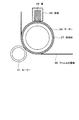
図1はこの色素増感光電変換素子を示す要部断面図である。
<1. First Embodiment>
[Dye-sensitized photoelectric conversion element]
FIG. 1 is a cross-sectional view of an essential part showing the dye-sensitized photoelectric conversion element.
図1に示すように、この色素増感光電変換素子においては、透明基板1の一主面に透明電極2が設けられ、この透明電極2上にこの透明電極2より小さい所定の平面形状を有する多孔質電極3が設けられている。この多孔質電極3には一種類または複数種類の光増感色素(図示せず)が結合している。一方、対向基板4の一主面に導電層5が設けられ、この導電層5上に対極6が設けられている。この対極6は多孔質電極3と同一の平面形状を有する。透明基板1上の多孔質電極3と対向基板4上の対極6との間に、電解液からなる電解質層7が設けられている。そして、これらの透明基板1および対向基板4の外周部が封止材8で封止されている。この封止材8は透明電極2および導電層5に接しているが、透明電極2を多孔質電極3と同一の平面形状に形成することにより透明基板1に接するようにしてもよいし、対極6を導電層5の全面に形成することによりこの導電層5に接するようにしてもよい。
As shown in FIG. 1, in this dye-sensitized photoelectric conversion element, a
多孔質電極3としては、典型的には、半導体微粒子を焼結させた多孔質半導体層が用いられる。光増感色素はこの半導体微粒子の表面に吸着している。半導体微粒子の材料としては、シリコンに代表される元素半導体、化合物半導体、ペロブスカイト構造を有する半導体などを用いることができる。これらの半導体は、光励起下で伝導帯電子がキャリアとなり、アノード電流を生じるn型半導体であることが好ましい。具体的には、例えば、酸化チタン(TiO2 )、酸化亜鉛(ZnO)、酸化タングステン(WO3 )、酸化ニオブ(Nb2 O5 )、チタン酸ストロンチウム(SrTiO3 )、酸化スズ(SnO2 )などの半導体が用いられる。これらの半導体の中でも、TiO2 、取り分けアナターゼ型のTiO2 を用いることが好ましい。ただし、半導体の種類はこれらに限定されるものではなく、必要に応じて、二種類以上の半導体を混合または複合化して用いることができる。また、半導体微粒子の形態は粒状、チューブ状、棒状などのいずれであってもよい。
As the
上記の半導体微粒子の粒径に特に制限はないが、一次粒子の平均粒径で1〜200nmが好ましく、特に好ましくは5〜100nmである。また、半導体微粒子よりも大きいサイズの粒子を混合し、この粒子で入射光を散乱させ、量子収率を向上させることも可能である。この場合、別途混合する粒子の平均サイズは20〜500nmであることが好ましいが、これに限定されるものではない。 Although there is no restriction | limiting in particular in the particle size of said semiconductor fine particle, 1-200 nm is preferable at the average particle diameter of a primary particle, Most preferably, it is 5-100 nm. It is also possible to improve the quantum yield by mixing particles having a size larger than that of the semiconductor fine particles and scattering incident light with these particles. In this case, the average size of the particles to be separately mixed is preferably 20 to 500 nm, but is not limited thereto.
多孔質電極3は、できるだけ多くの光増感色素を結合させることができるように、半導体微粒子からなる多孔質半導体層の内部の空孔に面する微粒子表面も含めた実表面積の大きいものが好ましい。このため、多孔質電極3を透明電極2の上に形成した状態での実表面積は、多孔質電極3の外側表面の面積(投影面積)に対して10倍以上であることが好ましく、100倍以上であることがさらに好ましい。この比に特に上限はないが、通常1000倍程度である。
The
一般に、多孔質電極3の厚さが増し、単位投影面積当たりに含まれる半導体微粒子の数が増加するほど、実表面積が増加し、単位投影面積に保持することができる光増感色素の量が増加するため、光吸収率が高くなる。一方、多孔質電極3の厚さが増加すると、光増感色素から多孔質電極3に移行した電子が透明電極2に達するまでに拡散する距離が増加するため、多孔質電極3内での電荷再結合による電子の損失も大きくなる。従って、多孔質電極3には好ましい厚さが存在するが、この厚さは一般的には0.1〜100μmであり、1〜50μmであることがより好ましく、3〜30μmであることが特に好ましい。
Generally, as the thickness of the
電解質層7を構成する電解液としては、ヨウ化物イオンよりもヨウ素分子と強い相互作用を示す化合物からなる添加剤を含むヨウ素レドックス系(酸化還元系)電解液が用いられる。このヨウ素レドックス系電解液の電解質としては、ヨウ素(I2 )と、ヨウ化リチウム(LiI)、ヨウ化ナトリウム(NaI)、イミダゾリウムヨーダイドなどの第4級アンモニウム化合物とを組み合わせた電解質が好適なものである。電解質塩の濃度は溶媒に対して0.05M〜10Mが好ましく、さらに好ましくは0.2M〜3Mである。ヨウ素I2 または臭素Br2 の濃度は0.0005M〜1Mが好ましく、さらに好ましくは0.001〜0.5Mである。また、開放電圧や短絡電流を向上させる目的で4−tert−ブチルピリジンやベンズイミダゾリウム類などの各種添加剤を加えることもできる。
As the electrolytic solution constituting the
ヨウ化物イオンよりもヨウ素分子と強い相互作用を示す化合物からなる添加剤の詳細について説明する。この添加剤としては、大きく分けて、非イオン性添加剤とイオン性添加剤とがある。非イオン性添加剤としては、共役酸の共役酸のpKa (H2 O)が9.12以上の非イオン性添加剤やアニオンの共役酸のpKa (H2 O)が4.76以上のイオン性添加剤などがある。非イオン性添加剤としては、例えば、下記のようなヘテロ環化合物、環状アミン、鎖状アミン、ジアミン、アミジン、グアニジン、ホスファゼンなどが挙げられ、これらの中から一つまたは二つ以上が用いられる。 The details of the additive composed of a compound having a stronger interaction with iodine molecules than iodide ions will be described. This additive is roughly classified into a nonionic additive and an ionic additive. Nonionic additives, pK a (H 2 O) of pK a (H 2 O) is a non-ionic additives and anions of the conjugate acid of more than 9.12 of conjugate acid of the conjugate acid 4.76 or more Ionic additives and the like. Nonionic additives include, for example, the following heterocyclic compounds, cyclic amines, chain amines, diamines, amidines, guanidines, phosphazenes, etc., and one or more of these are used. .
[非イオン性添加剤の例]
(1)ヘテロ環化合物(heterocycles)
・ピリジン(pyridine)
(1) Heterocycles
・ Pyridine
これらのヘテロ環化合物の具体例を挙げると、4−アミノピリジン(4-aminopyridine,4AMP)、4−N,N−ジメチルアミノピリジン(4-N,N-dimethylaminopyridine,4−DMN−Py)、4−ピロリジノピリジン(4-pyrrolidinopyridine,4−pyrr−Py)、4−アミノキノリン(4-aminoquinoline) 、4−アミノアクリジン(4-aminoacridine)などである。 Specific examples of these heterocyclic compounds include 4-aminopyridine (4-AMP), 4-N, N-dimethylaminopyridine (4-N, N-dimethylaminopyridine, 4-DMN-Py), 4 -Pyrrolidinopyridine (4-pyrrolidinopyridine, 4-pyrrr-Py), 4-aminoquinoline (4-aminoquinoline), 4-aminoacridine (4-aminoacridine) and the like.
(2)環状アミン(cyclic amine)
・ピロリジン(pyrrolidine)
・キヌクリジン(quinuclidine)
・ピペリジン(piperidine)
・モルホリン(morpholine)
・ Pyrrolidine
・ Quinuclidine
-Piperidine
・ Morpholine
これらの環状アミンにおいて、alkyl はmethyl、ethyl 、n-propyl、i-propyl、n-butyl 、i-butyl 、t-butyl 、hexyl 、octyl などの炭化水素基である。arene は、phenyl、thienyl 、benzylなどの芳香族系構造である。 In these cyclic amines, alkyl is a hydrocarbon group such as methyl, ethyl, n-propyl, i-propyl, n-butyl, i-butyl, t-butyl, hexyl, octyl and the like. arene is an aromatic structure such as phenyl, thienyl, or benzyl.
これらの環状アミンの具体例を挙げると、キヌクリジン(quinuclidine, Q)、3−ヒドロキシキヌクリジン(3-hydroxyquinuclidine)、3−アセトオキシキヌクリジン(3-acetooxyquinuclidine)、ピロリジン(pyrrolidine)、N−メチルピロリジン(N-methylpyrrolidine )、ピペリジン(piperidine) 、モルホリン(morpholine) などである。 Specific examples of these cyclic amines include quinuclidine (Q), 3-hydroxyquinuclidine, 3-acetooxyquinuclidine, pyrrolidine, N- Examples thereof include N-methylpyrrolidine, piperidine, and morpholine.
(3)鎖状アミン(linear amine)
・1級アミン(aliphatic amine)
・2級アミン(secondary amine)
・3級アミン(tertiary amine)
・ Primary amine
・ Secondary amine
・ Tertiary amine
これらの鎖状アミンにおいて、alkyl はmethyl、ethyl 、n-propyl、i-propyl、n-butyl 、i-butyl 、t-butyl 、hexyl 、octyl などの炭化水素基である。arene は、phenyl、thienyl 、benzylなどの芳香族系構造である。 In these chain amines, alkyl is a hydrocarbon group such as methyl, ethyl, n-propyl, i-propyl, n-butyl, i-butyl, t-butyl, hexyl, octyl and the like. arene is an aromatic structure such as phenyl, thienyl, or benzyl.
これらの鎖状アミンの具体例を挙げると、アンモニア(ammonia)、エタノールアミン(ethanolamine) 、トリエチルアミン(triethylamine)、n−ブチルアミン(n-butylamine) 、ジ−n−イソプロピルアミン(di-n-isopropylamine)などである。 Specific examples of these chain amines include ammonia, ethanolamine, triethylamine, n-butylamine, di-n-isopropylamine. Etc.
(4)ジアミン(diamine)
・鎖状ジアミン(linear diamine)
・ Linear diamine
これらのジアミンの具体例を挙げると、1,3−プロパンジアミン(1,3-propanediamine) 、3,7−ジブチル−3,7−ジアザビシクロ[3.3.1]ノナン(3,7-dibutyl-3,7-diazabicyclo[3.3.1 ]nonane)、1,8−ビス(ジメチルアミノ)ナフタレン(1,8-bis(dimethylamino)naphtalene) などである。 Specific examples of these diamines include 1,3-propanediamine, 3,7-dibutyl-3,7-diazabicyclo [3.3.1] nonane (3,7-dibutyl- 3,7-diazabicyclo [3.3.1] nonane), 1,8-bis (dimethylamino) naphthalene, and the like.
(5)アミジン(amidine)
これらのアミジンの具体例を挙げると、アセトアミジン(acetamidine)、1,5−ジアザビシクロ[4.3.0]ノン−5−エン(1,5-diazabicyclo[4.3.0 ]non-5-ene)、1,8−ジアザビシクロ[5.4.0]ウンデク−7−エン(1,8-diazabicyclo[5.4.0 ]undec-7-ene)などである。 Specific examples of these amidines include acetamidine, 1,5-diazabicyclo [4.3.0] non-5-ene (1,5-diazabicyclo [4.3.0] non-5-ene). 1,8-diazabicyclo [5.4.0] undec-7-ene (1,8-diazabicyclo [5.4.0] undec-7-ene) and the like.
(6)グアニジン(guanidine)
これらのグアニジンの具体例を挙げると、1,1,3,3−テトラメチルグアニジン(1,1,3,3-tetramethylguanidine)、1,5,7−トリアザビシクロ[4.4.0]デク−5−エン(1,5,7-triazabicyclo [4.4.0 ]dec-5-ene)、7−メチル−1,5,7−トリアザビシクロ[4.4.0]デク−5−エン(7-Methyl-1,5,7-triazabicyclo[4.4.0 ]dec-5-ene)などである。 Specific examples of these guanidines include 1,1,3,3-tetramethylguanidine, 1,5,7-triazabicyclo [4.4.0] dec -5-ene (1,5,7-triazabicyclo [4.4.0] dec-5-ene), 7-methyl-1,5,7-triazabicyclo [4.4.0] dec-5-ene ( 7-Methyl-1,5,7-triazabicyclo [4.4.0] dec-5-ene).
(7)ホスファゼン(phosphazene)
、benzylなどの芳香族系構造である。炭化水素基は置換されていてもよい。tmgは下記に示す通りである。
Aromatic structures such as benzyl. The hydrocarbon group may be substituted. tmg is as shown below.
これらのホスファゼンの具体例を挙げると、t−ブチルイミノ−トリス(ジメチルアミノ)ホスフォレーン(t-butylimino-tris(dimethylamino)phosphorane)、2−t−ブチルイミノ−2−ジエチルアミノ−1,3−ジメチルペルヒドロ−1,3,2−ジアザフォスホリン(2-t-butylimino-2-diethylamino-1,3-dimethylperhydro-1,3,2-diazaphosphorine)などである。 Specific examples of these phosphazenes include t-butylimino-tris (dimethylamino) phosphorane, 2-t-butylimino-2-diethylamino-1,3-dimethylperhydro- 1,3,2-diazaphosphorine (2-t-butylimino-2-diethylamino-1,3-dimethylperhydro-1,3,2-diazaphosphorine).
[イオン性添加剤の例]
イオン性添加剤はアニオンとカチオンとからなる。アニオンとしては、例えば、次のようなものが挙げられる。
(1)カルボキシアニオン(carboxylate anion)
COO−H酸の共役アニオンであり、下記の通りである。
The ionic additive consists of an anion and a cation. Examples of anions include the following.
(1) Carboxylate anion
It is a conjugated anion of COO-H acid and is as follows.
(2)アルコキシアニオン(alcholate anion)
O−H酸の共役アニオンであり、下記の通りである。
It is a conjugated anion of OH acid and is as follows.
(3)メルカプトアニオン(mercaptate anion)
S−H酸の共役アニオンであり、下記の通りである。
It is a conjugated anion of S—H acid and is as follows.
(4)炭素アニオン(carbon anion)
C−H酸の共役アニオンであり、下記の通りである。
It is a conjugated anion of C—H acid and is as follows.
(5)アミドアニオン(amide anion)
N−H酸の共役アニオンであり、下記の通りである。
It is a conjugated anion of NH acid and is as follows.
これらのアニオンにおいて、alkyl はmethyl、ethyl 、n-propyl、i-propyl、n-butyl 、i-butyl 、t-butyl 、hexyl 、octyl などの炭化水素基である。fluoroalkyl はCF3 、C2 F5 などのフッ素化炭化水素である。arene は、phenyl、thienyl 、benzylなどの芳香族系構造である。 In these anions, alkyl is a hydrocarbon group such as methyl, ethyl, n-propyl, i-propyl, n-butyl, i-butyl, t-butyl, hexyl, octyl and the like. Fluoroalkyl is a fluorinated hydrocarbon such as CF 3 or C 2 F 5 . arene is an aromatic structure such as phenyl, thienyl, or benzyl.
これらのアニオンの具体例を挙げると、アセテート(acetate)、2,2,2−テトラフルオロエタノエート,フェノレート(2,2,2-tetrafluoroethanoate,phenolate) 、エチルメルカプテート(ethyl mercaptate) 、アセチルアセトネート(acetylacetonate)、ヘキサフルオロアセチルアセトネート(hexafluoroacetylacetonate)、イミダゾレート(imidazolate)、1H−テトラゾレート(1H-tetrazolate)などである。 Specific examples of these anions include acetate, 2,2,2-tetrafluoroethanoate, phenolate, ethyl mercaptate, acetyl Examples thereof include acetonate, hexafluoroacetylacetonate, imidazolate and 1H-tetrazolate.
イオン性添加剤のカチオンは化学的に安定であれば基本的にはどのようなものであってもよいが、例えば、次のようなカチオンが挙げられる。
これらのカチオンの具体例を挙げると、アンモニウム(ammonium) 、イミダゾリウム(imidazolium)、ピロリジニウム(pyrrolidinium)、ピリジニウム(pyridinium) 、スルホニウム(sulfonium)、ホスホニウム(phosphonium)、ピペリジニウム(pipelidinium) 、モルホニウム(morphonium) などである。 Specific examples of these cations include ammonium, imidazolium, pyrrolidinium, pyridinium, sulfonium, phosphonium, piperidinium, and morphonium. Etc.
非イオン性添加剤としては、上記の中でも取り分け、
4−N,N−ジメチルアミノピリジン(4-N,N-dimethylaminopyridine,4−DMN−Py)
1−エチル−3−メチルイミダゾリウムアセテート(1-ethyl-3-methylimidazoliumacetate, EMImOAc)
4-N, N-dimethylaminopyridine (4-N, N-dimethylaminopyridine, 4-DMN-Py)
1-ethyl-3-methylimidazolium acetate (EMImOAc)
上記の四種類の非イオン性添加剤4AMP、4−DMN−Py、Qおよび4−pyrr−Pyならびに上記の二種類のイオン性添加剤のアニオンOAcおよびDAのpKa (H2 O)を表1に示す。表1には、参考のためにアセトニトリル(AN)中のpKa (AN)の値も示す。
Table The pK a (H 2 O) anionic OAc and DA of the four types of
表1に示すように、非イオン性添加剤である4AMP、4−DMN−PyおよびQのいずれも、pKa (H2 O)は9.12以上である。4−pyrr−PyのpKa (H2 O)は不明であるが、4−pyrr−PyのpKa (AN)はQのpKa (AN)と同等であることから、QのpKa (H2 O)と同等であると考えられ、従って9.12以上であると考えられる。また、イオン性添加剤であるEMImOAcおよびEMImDAのそれぞれのアニオンOAcおよびDAのいずれも、4.76以上である。 As shown in Table 1, none of the 4 AMP,4-DMN-Py and Q is a non-ionic additives, pK a (H 2 O) is 9.12 or more. 4-pyrr-Py of pK a (H 2 O) is unknown, since the 4-pyrr-Py of pK a (AN) is equivalent to pK a (AN) of Q, Q of pK a ( H 2 O) is considered to be equivalent, and is therefore considered to be greater than 9.12. In addition, each of the anions OAc and DA of the ionic additives EMImOAc and EMImDA is 4.76 or more.
電解液を構成する溶媒としては、一般的には、水、アルコール類、エーテル類、エステル類、炭酸エステル類、ラクトン類、カルボン酸エステル類、リン酸トリエステル類、複素環化合物類、ニトリル類、ケトン類、アミド類、ニトロメタン、ハロゲン化炭化水素、ジメチルスルホキシド、スルフォラン、N−メチルピロリドン、1,3−ジメチルイミダゾリジノン、3−メチルオキサゾリジノン、炭化水素などが用いられる。 As the solvent constituting the electrolytic solution, generally, water, alcohols, ethers, esters, carbonate esters, lactones, carboxylic acid esters, phosphate triesters, heterocyclic compounds, nitriles , Ketones, amides, nitromethane, halogenated hydrocarbons, dimethyl sulfoxide, sulfolane, N-methylpyrrolidone, 1,3-dimethylimidazolidinone, 3-methyloxazolidinone, hydrocarbons and the like are used.
電解液を構成する溶媒としてはイオン液体を用いてもよく、こうすることで電解液の揮発の問題を改善することができる。イオン液体としては従来公知のものを用いることができ、必要に応じて選ばれるが、具体例を挙げると次の通りである。 As a solvent constituting the electrolytic solution, an ionic liquid may be used, and by doing so, the problem of volatilization of the electrolytic solution can be improved. A conventionally well-known thing can be used as an ionic liquid, Although it chooses as needed, a specific example is as follows.
・EMImTCB:1−エチル−3−メチルイミダゾリウム テトラシアノボレート(1-ethyl-3-methylimidazolium tetracyanoborate)
・EMImTFSI:1−エチル−3−メチルイミダゾリウム ビス(トリフルオロメタンスルホニル)イミド(1-ethyl-3-methylimidazolium bis(trifluoromethanesulfonyl)imide)
・EMImFAP:1−エチル−3−メチルイミダゾリウム トリス(ペンタフルオロエチル)トリフルオロホスフェート(1-ethyl-3-methylimidazolium tris(pentafluoroethyl)trifluorophosphate)
・EMImBF4 :1−エチル−3−メチルイミダゾリウム テトラフルオロボレート(1-ethyl-3-methylimidazolium tetrafluoroborate)
・EMImOTf(1−エチル−3−メチルイミダゾリウム トリフルオロスルホネート(1-ethyl-3-methylimidazolium trifluorosulfonate) )
・P222 MOMTFSI(トリエチル(メトキシメチル)ホスホニウム ビス(トリフルオロメチルスホニル)イミド(triethyl(methoxymethyl)phosphonium bis(trifluoromethylsufonyl)imide)
EMImTCB: 1-ethyl-3-methylimidazolium tetracyanoborate
EMImTFSI: 1-ethyl-3-methylimidazolium bis (trifluoromethanesulfonyl) imide
EMImFAP: 1-ethyl-3-methylimidazolium tris (pentafluoroethyl) trifluorophosphate
EMImBF 4 : 1-ethyl-3-methylimidazolium tetrafluoroborate
EMImOTf (1-ethyl-3-methylimidazolium trifluorosulfonate)
・ P 222 MOMTFSI (triethyl (methoxymethyl) phosphonium bis (trifluoromethylsufonyl) imide)
透明基板1は、光が透過しやすい材質と形状のものであれば特に限定されるものではなく、種々の基板材料を用いることができるが、特に可視光の透過率が高い基板材料を用いることが好ましい。また、色素増感光電変換素子に外部から侵入しようとする水分やガスを阻止する遮断性能が高く、また、耐溶剤性や耐候性に優れている材料が好ましい。具体的には、透明基板1の材料としては、石英やガラスなどの透明無機材料や、ポリエチレンテレフタラート、ポリエチレンナフタラート、ポリカーボネート、ポリスチレン、ポリエチレン、ポリプロピレン、ポリフェニレンスルフィド、ポリフッ化ビニリデン、アセチルセルロース、ブロム化フェノキシ、アラミド類、ポリイミド類、ポリスチレン類、ポリアリレート類、ポリスルホン類、ポリオレフィン類などの透明プラスチックが挙げられる。透明基板1の厚さは特に制限されず、光の透過率や、光電変換素子内外を遮断する性能を勘案して、適宜選択することができる。
The
透明基板1上に設けられる透明電極2は、シート抵抗が小さいほど好ましく、具体的には500Ω/□以下であることが好ましく、100Ω/□以下であることがさらに好ましい。透明電極2を形成する材料としては公知の材料を用いることができ、必要に応じて選択される。この透明電極2を形成する材料は、具体的には、インジウム−スズ複合酸化物(ITO)、フッ素がドープされた酸化スズ(IV)SnO2 (FTO)、酸化スズ(IV)SnO2 、酸化亜鉛(II)ZnO、インジウム−亜鉛複合酸化物(IZO)などが挙げられる。ただし、透明電極2を形成する材料は、これらに限定されるものではなく、二種類以上を組み合わせて用いることもできる。
The
多孔質電極3に結合させる光増感色素は、増感作用を示すものであれば特に制限はなく、有機金属錯体、有機色素、金属・半導体ナノ粒子などを用いることができるが、この多孔質電極3の表面に吸着する酸官能基を有するものが好ましい。光増感色素は、一般的には、カルボキシ基、リン酸基などを有するものが好ましく、この中でも特にカルボキシ基を有するものが好ましい。光増感色素の具体例を挙げると、例えば、ローダミンB、ローズベンガル、エオシン、エリスロシンなどのキサンテン系色素、メロシアニン、キノシアニン、クリプトシアニンなどのシアニン系色素、フェノサフラニン、カブリブルー、チオシン、メチレンブルーなどの塩基性染料、クロロフィル、亜鉛ポルフィリン、マグネシウムポルフィリンなどのポルフィリン系化合物が挙げられ、その他のものとしてはアゾ色素、フタロシアニン化合物、クマリン系化合物、ピリジン錯化合物、アントラキノン系色素、多環キノン系色素、トリフェニルメタン系色素、インドリン系色素、ペリレン系色素、ポリチオフェンなどのπ共役系高分子やそのモノマーの2〜20量体、CdS、CdSeなどの量子ドットなどが挙げられる。これらの中でも、リガンド(配位子)がピリジン環またはイミダゾリウム環を含み、Ru、Os、Ir、Pt、Co、FeおよびCuからなる群より選ばれた少なくとも一種類の金属の錯体の色素は量子収率が高く好ましい。特に、シス−ビス(イソチオシアナート)−N,N−ビス(2,2’−ジピリジル−4,4’−ジカルボン酸)−ルテニウム(II)またはトリス(イソチオシアナート)−ルテニウム(II)−2,2' :6' ,2" −ターピリジン−4,4' ,4" −トリカルボン酸を基本骨格とする色素分子は吸収波長域が広く好ましい。ただし、光増感色素は、これらに限定されるものではない。光増感色素としては、典型的には、これらのうちの一種類のものを用いるが、二種類以上の光増感色素を混合して用いてもよい。二種類以上の光増感色素を混合して用いる場合、光増感色素は、好適には、多孔質電極3に保持された、MLCT(Metal to Ligand Charge Transfer)を引き起こす性質を有する無機錯体色素と、この多孔質電極3に保持された、分子内CT(Charge Transfer)の性質を有する有機分子色素とを有する。この場合、無機錯体色素と有機分子色素とは、多孔質電極3に互いに異なる立体配座で吸着する。無機錯体色素は、好適には、多孔質電極3に結合する官能基としてカルボキシ基またはホスホノ基を有する。また、有機分子色素は、好適には、同一炭素に、多孔質電極3に結合する官能基としてカルボキシ基またはホスホノ基とシアノ基、アミノ基、チオール基またはチオン基とを有する。無機錯体色素は例えばポリピリジン錯体、有機分子色素は例えば、電子供与性の基と電子受容性の基とを併せ持ち、分子内CTの性質を有する芳香族多環共役系分子である。
The photosensitizing dye to be bonded to the
光増感色素の多孔質電極3への吸着方法に特に制限はないが、上記の光増感色素を例えばアルコール類、ニトリル類、ニトロメタン、ハロゲン化炭化水素、エーテル類、ジメチルスルホキシド、アミド類、N−メチルピロリドン、1,3−ジメチルイミダゾリジノン、3−メチルオキサゾリジノン、エステル類、炭酸エステル類、ケトン類、炭化水素、水などの溶媒に溶解させ、これに多孔質電極3を浸漬したり、光増感色素を含む溶液を多孔質電極3上に塗布したりすることができる。また、光増感色素の分子同士の会合を低減する目的でデオキシコール酸などを添加してもよい。必要に応じて紫外線吸収剤を併用することもできる。
The method for adsorbing the photosensitizing dye to the
多孔質電極3に光増感色素を吸着させた後に、過剰に吸着した光増感色素の除去を促進する目的で、アミン類を用いて多孔質電極3の表面を処理してもよい。アミン類の例としてはピリジン、4−tert−ブチルピリジン、ポリビニルピリジンなどが挙げられ、これらが液体の場合はそのまま用いてもよいし、有機溶媒に溶解して用いてもよい。
After the photosensitizing dye is adsorbed on the
対極6の材料としては、導電性物質であれば任意のものを用いることができるが、絶縁性材料の電解質層7に面している側に導電層が形成されていれば、これも用いることが可能である。対極6の材料としては、電気化学的に安定な材料を用いることが好ましく、具体的には、白金、金、カーボン、導電性ポリマーなどを用いることが望ましい。
Any material can be used as the material for the
また、対極6での還元反応に対する触媒作用を向上させるために、電解質層7に接している対極6の表面は、微細構造が形成され、実表面積が増大するように形成されていることが好ましい。例えば、対極6の表面は、白金であれば白金黒の状態に、カーボンであれば多孔質カーボンの状態に形成されていることが好ましい。白金黒は、白金の陽極酸化法や塩化白金酸処理などによって、また多孔質カーボンは、カーボン微粒子の焼結や有機ポリマーの焼成などの方法によって形成することができる。
Further, in order to improve the catalytic action for the reduction reaction at the
対極6は対向基板4の一主面に形成された導電層5上に形成されているが、これに限定されるものではない。対向基板4の材料としては、不透明なガラス、プラスチック、セラミック、金属などを用いてもよいし、透明材料、例えば透明なガラスやプラスチックなどを用いてもよい。導電層5としては、透明電極2と同様なものを用いることができるほか、不透明な導電材料により形成されたものを用いることもできる。
The
封止材8の材料としては、耐光性、絶縁性、防湿性などを備えた材料を用いることが好ましい。封止材8の材料の具体例を挙げると、エポキシ樹脂、紫外線硬化樹脂、アクリル樹脂、ポリイソブチレン樹脂、EVA(エチレンビニルアセテート) 、アイオノマー樹脂、セラミック、各種熱融着フィルムなどである。
As a material of the sealing
また、電解液を注入する場合、注入口が必要であるが、多孔質電極3およびこれに対向する部分の対極6上でなければ注入口の場所は特に限定されない。また、電解液の注入方法に特に制限はないが、外周が予め封止され、溶液の注入口を開けられた光電変換素子の内部に減圧下で注液を行う方法が好ましい。この場合、注入口に溶液を数滴垂らし、毛細管現象により注液する方法が簡便である。また、必要に応じて減圧もしくは加熱下で注液の操作を行うこともできる。完全に溶液が注入された後、注入口に残った溶液を除去し、注入口を封止する。この封止方法にも特に制限はないが、必要であればガラス板やプラスチック基板を封止剤で貼り付けて封止することもできる。また、この方法以外にも、液晶パネルの液晶滴下注入(ODF;One Drop Filling)工程のように、電解液を基板上に滴下して減圧下で貼り合わせて封止することもできる。封止を行った後、電解液を多孔質電極3へ十分に含漬させるため、必要に応じて加熱、加圧の操作を行うことも可能である。
Moreover, when inject | pouring electrolyte solution, although an injection port is required, if it is not on the
[色素増感光電変換素子の製造方法]
次に、この色素増感光電変換素子の製造方法について説明する。
まず、透明基板1の一主面にスパッタリング法などにより透明導電層を形成して透明電極2を形成する。
[Method for producing dye-sensitized photoelectric conversion element]
Next, the manufacturing method of this dye-sensitized photoelectric conversion element is demonstrated.
First, the
次に、透明基板1の透明電極2上に多孔質電極3を形成する。この多孔質電極3の形成方法に特に制限はないが、物性、利便性、製造コストなどを考慮した場合、湿式製膜法を用いるのが好ましい。湿式製膜法では、半導体微粒子の粉末あるいはゾルを水などの溶媒に均一に分散させたペースト状の分散液を調製し、この分散液を透明基板1の透明電極2上に塗布または印刷する方法が好ましい。分散液の塗布方法または印刷方法に特に制限はなく、公知の方法を用いることができる。具体的には、塗布方法としては、例えば、ディップ法、スプレー法、ワイヤーバー法、スピンコート法、ローラーコート法、ブレードコート法、グラビアコート法などを用いることができる。また、印刷方法としては、凸版印刷法、オフセット印刷法、グラビア印刷法、凹版印刷法、ゴム版印刷法、スクリーン印刷法などを用いることができる。
Next, the
半導体微粒子の材料としてアナターゼ型TiO2 を用いる場合、このアナターゼ型TiO2 は、粉末状、ゾル状、またはスラリー状の市販品を用いてもよいし、酸化チタンアルコキシドを加水分解するなどの公知の方法によって所定の粒径のものを形成してもよい。市販の粉末を使用する際には粒子の二次凝集を解消することが好ましく、ペースト状分散液の調製時に、乳鉢やボールミルなどを使用して粒子の粉砕を行うことが好ましい。このとき、二次凝集が解消された粒子が再度凝集するのを防ぐために、アセチルアセトン、塩酸、硝酸、界面活性剤、キレート剤などをペースト状分散液に添加することができる。また、ペースト状分散液の粘性を増すために、ポリエチレンオキシドやポリビニルアルコールなどの高分子、あるいはセルロース系の増粘剤などの各種増粘剤をペースト状分散液に添加することもできる。 When anatase-type TiO 2 is used as the material for the semiconductor fine particles, this anatase-type TiO 2 may be a commercially available product in the form of powder, sol, or slurry, or is known such as hydrolyzing titanium oxide alkoxide. A material having a predetermined particle diameter may be formed by a method. When using a commercially available powder, it is preferable to eliminate secondary agglomeration of the particles, and it is preferable to pulverize the particles using a mortar, ball mill or the like when preparing the paste-like dispersion. At this time, acetylacetone, hydrochloric acid, nitric acid, a surfactant, a chelating agent, and the like can be added to the paste-like dispersion in order to prevent the particles from which secondary aggregation has been eliminated from aggregating again. In addition, in order to increase the viscosity of the paste-like dispersion, polymers such as polyethylene oxide and polyvinyl alcohol, or various thickeners such as a cellulose-based thickener can be added to the paste-like dispersion.
多孔質電極3は、半導体微粒子を透明電極2上に塗布または印刷した後に、半導体微粒子同士を電気的に接続し、多孔質電極3の機械的強度を向上させ、透明電極2との密着性を向上させるために、焼成することが好ましい。焼成温度の範囲に特に制限はないが、温度を上げ過ぎると、透明電極2の電気抵抗が高くなり、さらには透明電極2が溶融することもあるため、通常は40〜700℃が好ましく、40〜650℃がより好ましい。また、焼成時間にも特に制限はないが、通常は10分〜10時間程度である。
The
焼成後、半導体微粒子の表面積を増加させたり、半導体微粒子間のネッキングを高めたりする目的で、例えば、四塩化チタン水溶液や直径10nm以下の酸化チタン超微粒子ゾルによるディップ処理を行ってもよい。透明電極2を支持する透明基板1としてプラスチック基板を用いる場合には、結着剤を含むペースト状分散液を用いて透明電極2上に多孔質電極3を製膜し、加熱プレスによって透明電極2に圧着することも可能である。
For example, a dip treatment with a titanium tetrachloride aqueous solution or a titanium oxide ultrafine particle sol having a diameter of 10 nm or less may be performed for the purpose of increasing the surface area of the semiconductor fine particles or increasing the necking between the semiconductor fine particles. When a plastic substrate is used as the
次に、多孔質電極3が形成された透明基板1を、光増感色素を所定の有機溶媒に溶解した光増感色素溶液中に浸漬することにより、多孔質電極3に光増感色素を結合させる。
Next, the
一方、対向基板4の全面に例えばスパッタリング法などにより導電層5を形成した後、この導電層5上に所定の平面形状を有する対極6を形成する。この対極6は、例えば、導電層5の全面に例えばスパッタリング法などにより対極6の材料となる膜を形成した後、この膜をエッチングによりパターニングすることにより形成することができる。
On the other hand, after the
次に、透明基板1と対向基板4とを多孔質電極3と対極6とが所定の間隔、例えば1〜100μm、好ましくは1〜50μmの間隔をおいて互いに対向するように配置する。そして、透明基板1および対向基板4の外周部に封止材(図示せず)を形成して電解質層7が封入される空間を作り、この空間に例えば透明基板1に予め形成された注液口(図示せず)から電解液を注入し、電解質層7を形成する。この電解液としては、ヨウ素レドックス系電解液に、ヨウ化物イオンよりもヨウ素分子と強い相互作用を示す化合物からなる添加剤を単に加えて混合したものや、この添加剤を予めヨウ素などの呈色成分と相互作用させてから混合したものなどを用いる。その後、この注液口を塞ぐ。
以上により、目的とする色素増感光電変換素子が製造される。
Next, the
Thus, the target dye-sensitized photoelectric conversion element is manufactured.
[色素増感光電変換素子の動作]
次に、この色素増感光電変換素子の動作について説明する。
この色素増感光電変換素子は、光が入射すると、対極6を正極、透明電極2を負極とする電池として動作する。その原理は次の通りである。なお、ここでは、透明電極2の材料としてFTOを用い、多孔質電極3の材料としてTiO2 を用い、レドックス対としてI- /I3 - の酸化還元種を用いる。また、多孔質電極3に一種類の光増感色素が結合していることを想定する。
[Operation of dye-sensitized photoelectric conversion element]
Next, the operation of this dye-sensitized photoelectric conversion element will be described.
When light is incident, the dye-sensitized photoelectric conversion element operates as a battery having the
透明基板1および透明電極2を透過し、多孔質電極3に入射した光子を多孔質電極3に結合した光増感色素が吸収すると、この光増感色素中の電子が基底状態(HOMO)から励起状態(LUMO)へ励起される。こうして励起された電子は、光増感色素と多孔質電極3との間の電気的結合を介して、多孔質電極3を構成するTiO2 の伝導帯に引き出され、多孔質電極3を通って透明電極2に到達する。
When a photosensitizing dye that has passed through the
一方、電子を失った光増感色素は、電解質層7中の還元剤であるI- から下記の反応によって電子を受け取り、電解質層7中に酸化剤であるI3 - (I2 とI- との結合体)を生成する。
2I- → I2 + 2e-
I2 + I- → I3 -
On the other hand, the photosensitizing dye that has lost the electrons receives electrons from the reducing agent I − in the
2I − → I 2 + 2e −
I 2 + I - → I 3 -
こうして生成された酸化剤は拡散によって対極6に到達し、上記の反応の逆反応によって対極6から電子を受け取り、もとの還元剤に還元される。
I3 - → I2 + I-
I2 + 2e- → 2I-
The oxidant thus generated reaches the
I 3 - → I 2 + I -
I 2 + 2e - → 2I -
透明電極2から外部回路へ送り出された電子は、外部回路で電気的仕事をした後、対極6に戻る。このようにして、光増感色素にも電解質層7にも何の変化も残さず、光エネルギーが電気エネルギーに変換される。
The electrons sent from the
〈実施例1〉
色素増感光電変換素子を以下のようにして製造した。
多孔質電極3を形成する際の原料であるTiO2 のペースト状分散液は、「色素増感太陽電池の最新技術」(荒川裕則監修、2001年、(株)シーエムシー)を参考にして作製した。すなわち、まず、室温で撹拌しながらチタンイソプロポキシド125mlを0.1Mの硝酸水溶液750mlに徐々に滴下した。滴下後、80℃の恒温槽に移し、8時間撹拌を続けたところ、白濁した半透明のゾル溶液が得られた。このゾル溶液を室温になるまで放冷し、ガラスフィルタでろ過した後、溶媒を加えて溶液の体積を700mlにした。得られたゾル溶液をオートクレーブへ移し、220℃で12時間水熱反応を行わせた後、1時間超音波処理して分散化処理を行った。次に、この溶液をエバポレータを用いて40℃で濃縮し、TiO2 の含有量が20wt%になるように調製した。この濃縮ゾル溶液に、TiO2 の質量の20%分のポリエチレングリコール(分子量50万)と、TiO2 の質量の30%分の粒子直径200nmのアナターゼ型TiO2 とを添加し、撹拌脱泡機で均一に混合し、粘性を増加させたTi O2 のペースト状分散液を得た。
<Example 1>
A dye-sensitized photoelectric conversion element was produced as follows.
The paste-like dispersion of TiO 2 that is a raw material for forming the
上記のTiO2 のペースト状分散液を、透明電極2であるFTO層の上にブレードコーティング法によって塗布し、大きさ5mm×5mm、厚さ200μmの微粒子層を形成した。その後、500℃に30分間保持して、TiO2 微粒子をFTO層上に焼結した。焼結されたTiO2 膜へ0.1Mの塩化チタン(IV)TiCl4 水溶液を滴下し、室温下で15時間保持した後、洗浄し、再び500℃で30分間焼成を行った。この後、紫外光照射装置を用いてTiO2 焼結体に紫外光を30分間照射し、このTiO2 焼結体に含まれる有機物などの不純物をTiO2 の光触媒作用によって酸化分解して除去し、TiO2 焼結体の活性を高める処理を行い、多孔質電極3を得た。
The paste dispersion of TiO 2 was applied onto the FTO layer as the
光増感色素として、十分に精製した、下記の構造式で表されるZ907 23.8mgを、アセトニトリルとtert−ブタノールとを1:1の体積比で混合した混合溶媒50mlに溶解させ、光増感色素溶液を調製した。
こうして調製された光増感色素溶液を、多孔質電極3と同じ平面形状を有する不織布に染み込ませた。そして、室温下でこの光増感色素溶液を含む不織布を多孔質電極3に押圧してこの不織布からその光増感色素溶液を多孔質電極3に供給し、TiO2 微粒子表面に光増感色素を吸着させた。次に、4−tert−ブチルピリジンのアセトニトリル溶液およびアセトニトリルを順に用いて多孔質電極3を洗浄した後、暗所で溶媒を蒸発させ、乾燥させた。
The photosensitizing dye solution thus prepared was soaked into a nonwoven fabric having the same planar shape as the
対極6は、予め直径0.5mmの注液口が形成されたFTO層の上に厚さ50nmのクロム層および厚さ100nmの白金層を順次スパッタリング法によって積層し、その上に塩化白金酸のイソプロピルアルコール(2−プロパノール)溶液をスプレーコートし、385℃、15分間加熱することにより形成した。
The
次に、透明基板1と対向基板4とをそれらの多孔質電極3と対極6とが対向するように配置し、外周を厚さ30μmのアイオノマー樹脂フィルムとアクリル系紫外線硬化樹脂とによって封止した。
Next, the
一方、溶媒としての3−メトキシプロピオニトリル(MPN) 2.0gに、ヨウ化ナトリウムNaI 0.030g、1−プロピル−2,3−ジメチルイミダゾリウムヨーダイド 1.0g、ヨウ素I2 0.10g、そして添加剤として2−NH2−Py 0.054gに加えて、キヌクリジン(Q)を溶解させ、電解液を調製した。 Meanwhile, 2.0 g of 3-methoxypropionitrile (MPN) as a solvent, 0.030 g of sodium iodide NaI, 1.0 g of 1-propyl-2,3-dimethylimidazolium iodide, 0.10 g of iodine I 2 In addition to 0.054 g of 2-NH2-Py as an additive, quinuclidine (Q) was dissolved to prepare an electrolytic solution.
この電解液を予め準備した色素増感光電変換素子の注液口から送液ポンプを用いて注入し、減圧することで素子内部の気泡を追い出した。こうして電解質層7が形成される。次に、注液口をアイオノマー樹脂フィルム、アクリル樹脂およびガラス基板で封止し、色素増感光電変換素子を完成した。
This electrolytic solution was injected from a liquid injection port of a dye-sensitized photoelectric conversion element prepared in advance using a liquid feed pump, and the pressure inside the element was reduced to expel bubbles inside the element. Thus, the
〈実施例2〉
実施例2においては、電解液に加える添加剤としてキヌクリジンの代わりにEMImOAcを用いて調製した電解液を用いることを除いて、実施例1と同様にして色素増感光電変換素子を製造した。
<Example 2>
In Example 2, a dye-sensitized photoelectric conversion element was produced in the same manner as in Example 1 except that an electrolyte prepared using EMImOAc instead of quinuclidine was used as an additive to be added to the electrolyte.
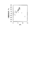
実施例1の色素増感光電変換素子において電解質層7を構成する電解液に加えるキヌクリジン(Q)の濃度を変えて色素増感光電変換素子の電流−電圧特性を測定した。測定は、色素増感光電変換素子に擬似太陽光(AM1.5、100mW/cm2 )を照射して行った。表2および図2にこの色素増感光電変換素子の光電変換効率(Eff)の測定結果を示す。表2および図2に示すように、測定した範囲では、光電変換効率(Eff)は0.25M付近で極大を取った後にQ濃度が高くなるにつれて減少する傾向が見られる。一方、Q濃度を変えたときの電解液の色を観察したところ、Q濃度が0.50Mから1.00Mではほとんど無色透明であり、その範囲ではQ濃度が高くなるほど透明度が高くなり、それ以下のQ濃度ではQ濃度が低くなるほど褐色の着色の度合いが強まった。
The current-voltage characteristics of the dye-sensitized photoelectric conversion element were measured by changing the concentration of quinuclidine (Q) added to the electrolyte solution constituting the
実施例2の色素増感光電変換素子において電解質層7を構成する電解液に加えるEMImOAcの濃度を変えて色素増感光電変換素子の電流−電圧特性を測定した。測定は、色素増感光電変換素子に擬似太陽光(AM1.5、100mW/cm2 )を照射して行った。表3および図3にこの色素増感光電変換素子の光電変換効率(Eff)の測定結果を示す。表3および図3に示すように、測定した範囲では、光電変換効率(Eff)は0.25M〜0.5M付近で極大を取った後にEMImOAc濃度が高くなるにつれて減少する傾向が見られる。一方、EMImOAc濃度を変えたときの電解液の色を観察したところ、EMImOAc濃度が1.00Mではほとんど無色透明であり、それ以下のEMImOAc濃度の範囲ではEMImOAc濃度が低くなるほど褐色の着色の度合いが強まった。
In the dye-sensitized photoelectric conversion element of Example 2, the current-voltage characteristics of the dye-sensitized photoelectric conversion element were measured by changing the concentration of EMImOAc added to the electrolyte solution constituting the
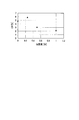
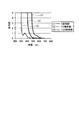
次に、電解液中の添加剤の濃度と電解液が褐色に着色する原因物質である三ヨウ化物イオン(I3 - )との関係を調べるためにUV−vis測定を行った。測定は、実施例1の電解液において添加剤として用いたキヌクリジン(Q)の代わりに4DMAMP(4−ジメチルアミノピリジン)を用いた電解液(0倍希釈)、この電解液をアセトニトリルにより10倍希釈した電解液(10倍希釈)、この電解液をアセトニトリルにより100倍希釈した電解液(100倍希釈)の三種類の電解液を調製した。図4にこれらの電解液のUV−vis測定の結果を示す。アセトニトリルにより100倍希釈した電解液の、I3 - の吸収波長に相当する波長360nmにおける吸光度を用いて4DMAMPの濃度([4DMAMP])に対してI3 - の濃度([I3 - ])をプロットした結果を図5に示す。その結果、[I3 - ]=A−B[4DMAMP]なる関係式が得られた。この式のAは添加剤を加えない状態での[I3 - ]、B=0.2195である。図5に示すように、[4DMAMP]が高くなるほど[I3 - ]は直線的に減少することがわかる。
Next, in order to investigate the relationship between the concentration of the additive in the electrolytic solution and triiodide ion (I 3 − ) which is a causative substance that the electrolytic solution is colored brown, UV-vis measurement was performed. The measurement was carried out by using an electrolyte (4 times dilution) using 4DMAPMP (4-dimethylaminopyridine) instead of quinuclidine (Q) used as an additive in the electrolyte of Example 1, and this electrolyte was diluted 10 times with acetonitrile. Three types of electrolyte solutions were prepared: an electrolyte solution (diluted 10 times) and an electrolyte solution (diluted 100 times) obtained by diluting the
以上のように、この第1の実施の形態によれば、電解質層7を構成する電解液として、ヨウ化物イオンよりもヨウ素分子と強い相互作用を示す化合物からなる添加剤を含むヨウ素レドックス系電解液を用いていることにより、光電変換特性をあまり低下させずに、電解質層7の無色透明化あるいは弱着色化が可能な色素増感光電変換素子を実現することができる。
As described above, according to the first embodiment, iodine redox electrolysis including an additive made of a compound having a stronger interaction with iodine molecules than iodide ions as the electrolyte solution constituting the
〈2.第2の実施の形態〉
[色素増感光電変換素子の製造方法]
第2の実施の形態による色素増感光電変換素子の製造方法においては、多孔質電極3への光増感色素の吸着を以下のようにして行う。
<2. Second Embodiment>
[Method for producing dye-sensitized photoelectric conversion element]
In the method of manufacturing the dye-sensitized photoelectric conversion element according to the second embodiment, the photosensitizing dye is adsorbed to the
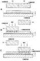
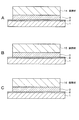
まず、図6Aに示すように、透明電極2が形成された透明基板1を図示省略した台の上に載せ、光増感色素を所定の溶媒に溶解した光増感色素溶液を保持する保持材9を多孔質電極3の上方に位置させる。図6Aにおいては、光増感色素溶液に含まれる光増感色素を模式的に点描で示す(以下、同様に光増感色素を模式的に点描で示す)。保持材9の平面形状は、多孔質電極3とほぼ同一形状を有する。保持材9は、光増感色素溶液の保持能力を有している限り、どのようなものであってもよいが、例えば、不織布、紙、スポンジ、ペースト、ゲルなどである。
First, as shown in FIG. 6A, a
次に、図6Bに示すように、保持材9を下降させて多孔質電極3に接触させた後、さらに図示省略した押圧板により保持材9を上方から多孔質電極3に押圧する。このとき、保持材9が圧縮されることにより、その内部に保持された光増感色素溶液が押圧面に押し出され、多孔質電極3に供給される。こうして多孔質電極3に供給された光増感色素溶液はこの多孔質電極3の内部に行き渡り、光増感色素が吸着する。この場合、従来のように、多孔質電極3が形成された透明基板1を光増感色素溶液中に浸漬することにより多孔質電極3に光増感色素を吸着させる場合と比べて、使用する光増感色素溶液の量の大幅な低減を図ることができる。また、多孔質電極3が形成された透明基板1を光増感色素溶液中に浸漬する方法では、光増感色素溶液を繰り返し使用する間に汚染されたり、溶液組成が変化したりするおそれがあるのに対し、上述の方法では、光増感色素溶液を保持する保持材9を多孔質電極3に押圧することにより光増感色素溶液を多孔質電極3に供給するので、毎回、汚染がなく新鮮で組成も一定の光増感色素溶液を多孔質電極3に供給することができる。
この後、図6Cに示すように、保持材9を上昇させる。
Next, as shown in FIG. 6B, the holding
Thereafter, as shown in FIG. 6C, the holding
この色素増感光電変換素子の製造方法の上記以外のことは第1の実施の形態による色素増感光電変換素子の製造方法と同様である。 The manufacturing method of the dye-sensitized photoelectric conversion element other than the above is the same as the manufacturing method of the dye-sensitized photoelectric conversion element according to the first embodiment.
〈実施例3〉
色素増感光電変換素子を以下のようにして製造した。
多孔質電極3を形成する際の原料であるTiO2 のペースト状分散液は、「色素増感太陽電池の最新技術」(荒川裕則監修、2001年、(株)シーエムシー)を参考にして作製した。すなわち、まず、室温で撹拌しながらチタンイソプロポキシド125mlを0.1Mの硝酸水溶液750mlに徐々に滴下した。滴下後、80℃の恒温槽に移し、8時間撹拌を続けたところ、白濁した半透明のゾル溶液が得られた。このゾル溶液を室温になるまで放冷し、ガラスフィルタでろ過した後、溶媒を加えて溶液の体積を700mlにした。得られたゾル溶液をオートクレーブへ移し、220℃で12時間水熱反応を行わせた後、1時間超音波処理して分散化処理を行った。次に、この溶液をエバポレータを用いて40℃で濃縮し、TiO2 の含有量が20wt%になるように調製した。この濃縮ゾル溶液に、TiO2 の質量の20%分のポリエチレングリコール(分子量50万)と、TiO2 の質量の30%分の粒子直径200nmのアナターゼ型TiO2 とを添加し、撹拌脱泡機で均一に混合し、粘性を増加させたTi O2 のペースト状分散液を得た。
<Example 3>
A dye-sensitized photoelectric conversion element was produced as follows.
The paste-like dispersion of TiO 2 that is a raw material for forming the
上記のTiO2 のペースト状分散液を、透明電極2であるFTO層の上にブレードコーティング法によって塗布し、大きさ5mm×5mm、厚さ200μmの微粒子層を形成した。その後、500℃に30分間保持して、TiO2 微粒子をFTO層上に焼結した。焼結されたTiO2 膜へ0.1Mの塩化チタン(IV)TiCl4 水溶液を滴下し、室温下で15時間保持した後、洗浄し、再び500℃で30分間焼成を行った。この後、紫外光照射装置を用いてTiO2 焼結体に紫外光を30分間照射し、このTiO2 焼結体に含まれる有機物などの不純物をTiO2 の光触媒作用によって酸化分解して除去し、TiO2 焼結体の活性を高める処理を行い、多孔質電極3を得た。
The paste dispersion of TiO 2 was applied onto the FTO layer as the
光増感色素として、十分に精製したZ907 23.8mgを、アセトニトリルとtert−ブタノールとを1:1の体積比で混合した混合溶媒50mlに溶解させ、光増感色素溶液を調製した。 As a photosensitizing dye, 23.8 mg of fully purified Z907 was dissolved in 50 ml of a mixed solvent in which acetonitrile and tert-butanol were mixed at a volume ratio of 1: 1 to prepare a photosensitizing dye solution.
こうして調製された光増感色素溶液を、多孔質電極3と同じ平面形状を有する不織布に染み込ませた。そして、室温下でこの光増感色素溶液を含む不織布を多孔質電極3に押圧してこの不織布からその光増感色素溶液を多孔質電極3に供給し、TiO2 微粒子表面に光増感色素を吸着させた。次に、4−tert−ブチルピリジンのアセトニトリル溶液およびアセトニトリルを順に用いて多孔質電極3を洗浄した後、暗所で溶媒を蒸発させ、乾燥させた。
The photosensitizing dye solution thus prepared was soaked into a nonwoven fabric having the same planar shape as the
対極6は、予め直径0.5mmの注液口が形成されたFTO層の上に厚さ50nmのクロム層および厚さ100nmの白金層を順次スパッタリング法によって積層し、その上に塩化白金酸のイソプロピルアルコール(2−プロパノール)溶液をスプレーコートし、385℃、15分間加熱することにより形成した。
The
次に、透明基板1と対向基板4とをそれらの多孔質電極3と対極6とが対向するように配置し、外周をアイオノマー樹脂フィルムとアクリル系紫外線硬化樹脂とによって封止した。
Next, the
一方、溶媒としての3−メトキシプロピオニトリル(MPN) 2.0gに、ヨウ化ナトリウムNaI 0.030g、1−プロピル−2,3−ジメチルイミダゾリウムヨーダイド 1.0g、ヨウ素I2 0.10g、そして添加剤として2−NH2−Py 0.054gに加えて、キヌクリジン(Q)を溶解させ、電解液を調製した。 Meanwhile, 2.0 g of 3-methoxypropionitrile (MPN) as a solvent, 0.030 g of sodium iodide NaI, 1.0 g of 1-propyl-2,3-dimethylimidazolium iodide, 0.10 g of iodine I 2 In addition to 0.054 g of 2-NH2-Py as an additive, quinuclidine (Q) was dissolved to prepare an electrolytic solution.
この電解液を予め準備した色素増感光電変換素子の注液口から送液ポンプを用いて注入し、減圧することで素子内部の気泡を追い出した。こうして電解質層7が形成される。次に、注液口をアイオノマー樹脂フィルム、アクリル樹脂およびガラス基板で封止し、色素増感光電変換素子を完成した。
This electrolytic solution was injected from a liquid injection port of a dye-sensitized photoelectric conversion element prepared in advance using a liquid feed pump, and the pressure inside the element was reduced to expel bubbles inside the element. Thus, the
以上のように、この第2の実施の形態によれば、第1の実施の形態と同様な利点に加えて、次のような利点を得ることができる。すなわち、光増感色素溶液を保持する保持材9を多孔質電極3に押圧することによりこの保持材9からその内部の光増感色素溶液を多孔質電極3に供給し、それによって光増感色素を多孔質電極3に吸着させている。このため、光増感色素を多孔質電極3に極めて簡単に吸着させることができ、色素増感光電変換素子の製造コストの低減を図ることができる。また、光増感色素溶液は必要最小限の量で済むため、使用する光増感色素溶液の量の大幅な低減を図ることができる。さらに、従来のように光増感色素溶液に多孔質電極3を浸漬することにより光増感色素を吸着させる方法では、光増感色素溶液の汚染や組成変化などが生じたりするおそれがあるのに対し、この第1の実施の形態によれば、保持材9により押圧する毎に、汚染がなく新鮮で組成も一定の光増感色素溶液を供給することができ、光増感色素溶液の汚染や組成変化などに起因する問題がない。これによって、光電変換特性が優れた色素増感光電変換素子を低コストで製造することができる。
As described above, according to the second embodiment, in addition to the same advantages as those of the first embodiment, the following advantages can be obtained. That is, the holding
〈3.第3の実施の形態〉
[色素増感光電変換素子の製造方法]
上述のように、第2の実施の形態においては、多孔質電極3とほぼ同一の平面形状を有し、光増感色素溶液を保持する保持材9による一回の押圧により多孔質電極3の全面に光増感色素溶液を供給し、多孔質電極3の全体に光増感色素を吸着させている。これに対し、第2の実施の形態においては、多孔質電極3の面積よりも断面積が小さい保持材9を用い、この保持材9を多孔質電極3上で場所を変えながら複数回、多孔質電極3に押圧することにより、最終的に多孔質電極3の全体に光増感色素を吸着させる。
<3. Third Embodiment>
[Method for producing dye-sensitized photoelectric conversion element]
As described above, in the second embodiment, the
すなわち、第3の実施の形態においては、図7Aに示すように、多孔質電極3の面積よりも断面積が小さい保持材9を多孔質電極3の端部に近い部分の上方に位置させる。保持材9の断面の形状は必要に応じて選ばれ、種々の形状であってもよいが、例えば長方形や正方形などである。
That is, in the third embodiment, as shown in FIG. 7A, the holding
次に、図7Bに示すように、保持材9を下降させて多孔質電極3に押圧し、この保持材9からその内部に保持された光増感色素溶液を多孔質電極3に供給する。
Next, as shown in FIG. 7B, the holding
次に、図7Cに示すように、保持材9を一端上昇させてから水平方向に移動し、保持材9による一回目の押圧領域に隣接した領域の上方に位置させ、その後、下降させて多孔質電極3に押圧し、この保持材9からその内部に保持された光増感色素溶液を多孔質電極3に供給する。
Next, as shown in FIG. 7C, the holding
次に、図7Dに示すように、保持材9を一端上昇させてから水平方向に移動し、保持材9による二回目の押圧領域に隣接した領域の上方に位置させ、その後、下降させて多孔質電極3に押圧し、この保持材9からその内部に保持された光増感色素溶液を多孔質電極3に供給する。
Next, as shown in FIG. 7D, the holding
必要に応じて上記と同様な操作を繰り返して、多孔質電極3の全面に光増感色素溶液を供給する。これによって、多孔質電極3の全体に光増感色素を吸着させることができる。
If necessary, the same operation as above is repeated to supply the photosensitizing dye solution to the entire surface of the
第3の実施の形態の上記以外のことは第2の実施の形態と同様である。
この第3の実施の形態によれば、第2の実施の形態と同様な利点を得ることができる。
Except for the above, the third embodiment is the same as the second embodiment.
According to the third embodiment, advantages similar to those of the second embodiment can be obtained.
〈4.第4の実施の形態〉
[色素増感光電変換素子の製造方法]
第4の実施の形態においては、多色の色素増感光電変換素子を製造する場合について説明する。
<4. Fourth Embodiment>
[Method for producing dye-sensitized photoelectric conversion element]
In the fourth embodiment, a case where a multicolor dye-sensitized photoelectric conversion element is manufactured will be described.
図8A〜Cはこの第4の実施の形態における多孔質電極3への光増感色素の吸着工程を示す。
8A to 8C show a photosensitizing dye adsorption process to the
第4の実施の形態においては、図8Aに示すように、多孔質電極3の上面をそれぞれ所定の平面形状を有する複数の領域に分割した面積とほぼ等しい断面積を有する複数の保持材(ここでは例えば二つの保持材9a、9b)を用意し、これらを同一面上に互いに隣接して配置する。互いに光吸収特性が異なる複数種類の光増感色素をそれぞれ溶解した複数種類(ここでは例えば二種類)の光増感色素溶液を調製し、これらの光増感色素溶液をそれぞれの保持材9a、9bに保持しておく。図8Aにおいては、二種類の光増感色素溶液に含まれる二種類の光増感色素を模式的に互いに大きさが異なる点描で示す(以下、同様に二種類の光増感色素を模式的に互いに大きさが異なる点描で示す)。
In the fourth embodiment, as shown in FIG. 8A, a plurality of holding materials (here, having a cross-sectional area substantially equal to an area obtained by dividing the upper surface of the
次に、図8Bに示すように、これらの保持材9a、9bを同時に下降させて多孔質電極3に押圧し、これらの保持材9a、9bからその内部に保持されたそれぞれの光増感色素溶液を多孔質電極3に供給する。これによって、多孔質電極3の一方の片側の領域には保持材9aに保持された光増感色素溶液からの光増感色素が吸着し、他方の片側の領域には保持材9bに保持された光増感色素溶液からの光増感色素が吸着する。
この後、図8Cに示すように、保持材9a、9bを上昇させる。
Next, as shown in FIG. 8B, these holding
Thereafter, as shown in FIG. 8C, the holding
ここでは、互いに異なる光増感色素溶液を保持した二つの保持材9a、9bを用いる場合について説明したが、これに限定されるものではなく、保持材の数、保持材の先端面(押圧に用いられる面)の形状、保持材による押圧位置などは、色素増感光電変換素子によって多色で表示しようとする模様(画像)に応じて適宜選ばれる。また、これらの複数の保持材に保持させる光増感色素溶液は、色素増感光電変換素子によって多色で表示しようとする模様に応じて適宜選ばれる。これらの複数の保持材のうちの二つ以上の保持材が同一の光増感色素溶液を保持するようにしてもよい。
Here, the case where two holding
第4の実施の形態の上記以外のことは第2の実施の形態と同様である。
この第4の実施の形態によれば、第2の実施の形態と同様な利点に加えて、次のような利点を得ることができる。すなわち、多孔質電極3のうちの互いに異なる複数の領域に吸着させる光増感色素の選択により、これらの領域が互いに異なる多色の模様などの外観を呈する色素増感光電変換素子を、製造工程を複雑化することなく簡単に製造することができる。しかも、互いに異なる光増感色素溶液をそれぞれ保持する複数の保持材(例えば、保持材9a、9b)を多孔質電極3の上面の各部位に押圧するだけで各光増感色素溶液を選択的に供給することができるので、各領域に各光増感色素をにじみを抑えつつ吸着させることができる。このため、多孔質電極3のうちの互いに種類が異なる光増感色素が吸着した複数の領域間の境界を鮮明にすることができ、多色に色分けした領域を明確な境界をもって形成することができ、高画質でコントラスト制御が容易な色素増感光電変換素子を容易に実現することができる。
Except for the above, the fourth embodiment is the same as the second embodiment.
According to the fourth embodiment, in addition to the same advantages as those of the second embodiment, the following advantages can be obtained. That is, by selecting a photosensitizing dye to be adsorbed in a plurality of different regions of the
〈5.第5の実施の形態〉
[色素増感光電変換素子の製造方法]
第5の実施の形態においては、多色の色素増感光電変換素子を製造する場合について説明する。
<5. Fifth Embodiment>
[Method for producing dye-sensitized photoelectric conversion element]
In the fifth embodiment, a case where a multicolor dye-sensitized photoelectric conversion element is manufactured will be described.
図9A〜Cはこの第5の実施の形態における多孔質電極3への光増感色素の吸着工程を示す。
9A to 9C show a photosensitizing dye adsorption step on the
第5の実施の形態においては、図9Aに示すように、多孔質電極3の上面を複数の領域に分割した面積とほぼ等しい断面積を有する複数の保持材(ここでは、二つの保持材9a、9b)を用意し、これらを同一面上に互いに隣接して配置する。互いに光吸収特性が異なる複数種類の光増感色素をそれぞれ溶解した複数種類の光増感色素溶液を調製し、これらの光増感色素溶液をそれぞれの保持材9a、9bに保持しておく。
In the fifth embodiment, as shown in FIG. 9A, a plurality of holding materials (here, two holding
次に、図9Bに示すように、例えば、まず保持材9aを下降させて多孔質電極3に押圧し、この保持材9aからその内部に保持された光増感色素溶液を多孔質電極3に供給する。これによって、多孔質電極3の一方の片側の領域に保持材9aに保持された光増感色素溶液からの光増感色素が吸着する。この後、保持材9aを上昇させる。
Next, as shown in FIG. 9B, for example, the holding
次に、図9Cに示すように、保持材9bを下降させて多孔質電極3に押圧し、この保持材9bからその内部に保持された光増感色素溶液を多孔質電極3に供給する。これによって、多孔質電極3の他方の片側の領域に保持材9bに保持された光増感色素溶液からの光増感色素が吸着する。この後、保持材9bを上昇させる。
Next, as shown in FIG. 9C, the holding
ここでは、互いに異なる光増感色素溶液を保持した二つの保持材9a、9bを用いる場合について説明したが、これに限定されるものではなく、保持材の数は必要に応じて選ばれる。また、これらの複数の保持材に互いに異なる光増感色素溶液をそれぞれ保持させてもよいし、これらの複数の保持材のうちの二つ以上の保持材が同一の光増感色素溶液を保持するようにしてもよい。
Here, the case where two holding
第5の実施の形態の上記以外のことは第2の実施の形態と同様である。
この第5の実施の形態によれば、第2の実施の形態と同様な利点に加えて、第4の実施の形態と同様な利点を得ることができる。
Except for the above, the fifth embodiment is the same as the second embodiment.
According to the fifth embodiment, in addition to the same advantages as those of the second embodiment, the same advantages as those of the fourth embodiment can be obtained.
〈6.第6の実施の形態〉
[色素増感光電変換素子の製造方法]
第6の実施の形態においては、多孔質電極3に光増感色素を吸着させた後に、何らかの目的でこの多孔質電極3から選択的に光増感色素を脱離させる方法について説明する。
図10A〜Cはこの多孔質電極3からの光増感色素の脱離工程を示す。
<6. Sixth Embodiment>
[Method for producing dye-sensitized photoelectric conversion element]
In the sixth embodiment, a method of selectively desorbing the photosensitizing dye from the
FIGS. 10A to 10C show a desorption process of the photosensitizing dye from the
図10Aに示すように、全体に光増感色素を吸着させた多孔質電極3の上方に、光増感色素脱離用の溶液、例えばアルカリ溶液を保持する保持材10を位置させる。
As shown in FIG. 10A, a holding
次に、図10Bに示すように、この保持材10を下降させて多孔質電極3を選択的に押圧し、この保持材10からその内部に保持された光増感色素脱離用の溶液を多孔質電極3に供給する。これによって、この保持材10による押圧領域から光増感色素脱離用の溶液が多孔質電極3に浸透し、図10Cに示すように、この部分の光増感色素が選択的に脱離する。
Next, as shown in FIG. 10B, the holding
第6の実施の形態の上記以外のことは第1の実施の形態と同様である。
この第6の実施の形態によれば、第2の実施の形態と同様な利点に加えて、多孔質電極3の所望の領域から容易に光増感色素を脱離させることができるという利点を得ることができる。
Except for the above, the sixth embodiment is the same as the first embodiment.
According to the sixth embodiment, in addition to the same advantages as those of the second embodiment, the advantage that the photosensitizing dye can be easily detached from a desired region of the
〈7.第7の実施の形態〉
[色素増感光電変換素子の製造方法]
第7の実施の形態においては、第2の実施の形態による色素増感光電変換素子の製造方法において、透明基板1上に形成された透明電極2の表面をTiCl4 水溶液で処理する工程(工程A)、その後に透明電極2の表面を水、エタノールにより洗浄する工程(工程B)、焼成により多孔質電極3を形成した後、この多孔質電極3の表面をTiCl4 水溶液で処理する工程(工程C)、その後にこの多孔質電極3の表面を水、エタノールにより洗浄する工程(工程D)、多孔質電極3に光増感色素を吸着させた後に、多孔質電極3を洗浄液、例えばアセトニトリルにより洗浄する工程(工程E)、および、その後に多孔質電極3に電解液を含浸させる工程(工程F)のいずれか一つまたは二つ以上を、液を保持する保持材による押圧により実行する。
<7. Seventh Embodiment>
[Method for producing dye-sensitized photoelectric conversion element]
In the seventh embodiment, in the method for manufacturing the dye-sensitized photoelectric conversion element according to the second embodiment, the surface of the
工程Aにおいては、図11Aに示すように、TiCl4 水溶液を保持する保持材11を透明電極2の表面に押圧してこの保持材11からTiCl4 水溶液を透明電極2の表面に供給し、このTiCl4 水溶液により透明電極2の表面を処理する。必要に応じて、保持材11の断面積を透明電極2の面積よりも小さくすることにより、透明電極2の表面を部分的に処理してもよいし、保持材11による複数回の押圧により透明電極2の表面の全体を処理するようにしてもよい。
In step A, as shown in FIG. 11A, the holding
工程Bにおいては、図11Bに示すように、例えば水またはエタノールを保持する保持材12を透明電極2の表面に押圧してこの保持材12から水またはエタノールを透明電極2の表面に供給し、この水またはエタノールにより透明電極2の表面を洗浄する。必要に応じて、保持材12の断面積を透明電極2の面積よりも小さくすることにより、透明電極2の表面を部分的に洗浄してもよいし、保持材12による複数回の押圧により透明電極2の表面の全体を洗浄するようにしてもよい。
In step B, as shown in FIG. 11B, for example, the holding material 12 holding water or ethanol is pressed against the surface of the
工程Cにおいては、図11Cに示すように、TiCl4 水溶液を保持する保持材13を多孔質電極3の表面に押圧してこの保持材13からTiCl4 水溶液を多孔質電極3の表面に供給し、このTiCl4 水溶液により多孔質電極3の表面を処理する。必要に応じて、保持材13の断面積を多孔質電極3の面積よりも小さくすることにより、多孔質電極3の表面を部分的に処理してもよいし、保持材13による複数回の押圧により多孔質電極3の表面の全体を処理するようにしてもよい。
In step C, as shown in FIG. 11C, the holding material 13 holding the TiCl 4 aqueous solution is pressed against the surface of the
工程Dにおいては、図12Aに示すように、例えば水またはエタノールを保持する保持材14を多孔質電極3の表面に押圧してこの保持材14から水またはエタノールを多孔質電極3の表面に供給し、この水またはエタノールにより多孔質電極3の表面を洗浄する。必要に応じて、保持材14の断面積を多孔質電極3の面積よりも小さくすることにより、多孔質電極3の表面を部分的に洗浄してもよいし、保持材14による複数回の押圧により多孔質電極3の表面の全体を洗浄するようにしてもよい。
In step D, as shown in FIG. 12A, for example, a holding material 14 holding water or ethanol is pressed against the surface of the
工程Eにおいては、図12Bに示すように、例えばアセトニトリルを保持する保持材15を多孔質電極20表面に押圧してこの保持材15からアセトニトリルを多孔質電極3の表面に供給し、このアセトニトリルにより多孔質電極3の表面を洗浄する。必要に応じて、保持材15の断面積を多孔質電極3の面積よりも小さくすることにより、多孔質電極3の表面を部分的に洗浄してもよいし、保持材15による複数回の押圧により多孔質電極3の表面の全体を洗浄するようにしてもよい。
In the step E, as shown in FIG. 12B, for example, the holding
工程Fにおいては、図12Cに示すように、電解液を保持する保持材16を多孔質電極3の表面に押圧してこの保持材16から電解液を多孔質電極3の表面に供給し、この多孔質電極3に電解液を含浸させる。必要に応じて、保持材16の断面積を多孔質電極3の面積よりも小さくすることにより、多孔質電極3に部分的に電解液を含浸させてもよいし、保持材16による複数回の押圧により多孔質電極3の全体に電解液を含浸させてもよい。
In step F, as shown in FIG. 12C, the holding material 16 holding the electrolytic solution is pressed against the surface of the
第7の実施の形態の上記以外のことは第2の実施の形態と同様である。
この第7の実施の形態によれば、第2の実施の形態と同様な利点に加えて、透明電極2および多孔質電極3の表面の処理や洗浄を容易に行うことができるという利点を得ることができる。
Except for the above, the seventh embodiment is the same as the second embodiment.
According to the seventh embodiment, in addition to the same advantages as those of the second embodiment, there is an advantage that the surface and the cleaning of the
〈8.第8の実施の形態〉
[色素増感光電変換素子の製造方法]
第8の実施の形態においては、第2の実施の形態による色素増感光電変換素子の製造方法において、電解液の注入を、電解液を保持する保持材による押圧により行う。
図13A〜Cはこの電解液の注入工程を示す。
<8. Eighth Embodiment>
[Method for producing dye-sensitized photoelectric conversion element]
In the eighth embodiment, in the method of manufacturing the dye-sensitized photoelectric conversion element according to the second embodiment, the electrolyte solution is injected by pressing with a holding material that holds the electrolyte solution.
13A to 13C show the injection process of this electrolytic solution.
図13Aに示すように、透明基板1上の透明電極2上に多孔質電極3を形成し、透明電極2の外周部に封止材8を塗布した後、多孔質電極3の上方に、電解液を保持する保持材17を位置させる。
As shown in FIG. 13A, the
次に、図13Bに示すように、電解液を保持する保持材17を多孔質電極3の表面に押圧してこの保持材17から電解液を多孔質電極3の表面に供給し、この多孔質電極3上に電解液18を付着させる。
次に、図13Cに示すように、保持材13を上昇させる。
この後、対極6を封止材8に貼り合わせて色素増感光電変換素子を製造する。
Next, as shown in FIG. 13B, the holding
Next, as shown in FIG. 13C, the holding material 13 is raised.
Thereafter, the
第8の実施の形態の上記以外のことは第2の実施の形態と同様である。
この第8の実施の形態によれば、第2の実施の形態と同様な利点に加えて、次のような利点を得ることができる。すなわち、従来のODFを用いて電解液を注入する場合には、透明基板1上の透明電極2上に多孔質電極3を形成し、透明電極2の外周部に封止材8を塗布した後、多孔質電極3の上方からODFにより電解液を供給する。しかしながら、この方法では、電解液の近傍に未硬化の封止材8が存在することから、電解液がこの未硬化の状態の封止材8に接触すると、硬化不良や電解液のリークなどを引き起こすため、注液条件の制御が必要であり、煩雑である。これに対し、この第7の実施の形態によれば、電解液を保持する保持材17を多孔質電極3に押圧することにより電解液18を多孔質電極3上に付着させるため、所望の部位に正確に電解液18を注入することができる。
Except for the above, the eighth embodiment is the same as the second embodiment.
According to the eighth embodiment, in addition to the same advantages as those of the second embodiment, the following advantages can be obtained. That is, when the electrolytic solution is injected using a conventional ODF, the
〈9.第9の実施の形態〉
[色素増感光電変換素子の製造方法]
色素増感光電変換素子をロール・ツー・ロール(roll-to-roll)プロセスにより製造する試みが行われている。第9の実施の形態においては、ロール・ツー・ロールプロセスにより色素増感光電変換素子を製造する場合に、液を使用する各種の工程を液を保持する保持材を押圧することにより実行する方法について説明する。
<9. Ninth Embodiment>
[Method for producing dye-sensitized photoelectric conversion element]
Attempts have been made to produce dye-sensitized photoelectric conversion elements by a roll-to-roll process. In the ninth embodiment, when a dye-sensitized photoelectric conversion element is manufactured by a roll-to-roll process, various processes using a liquid are performed by pressing a holding material that holds the liquid. Will be described.
図14はスタンプ工程により液を所望の部位に所望の量だけ供給する方法を示す。図14に示すように、透明なベースフィルム上に電極を形成したフィルム状電極19をローラー20、21により送ることができるように構成された製造装置を用いる。ローラー20、21の間の部分のフィルム状電極19は、典型的には、水平になるようにする。この水平なフィルム状電極19の上方にスタンプ22を位置させる。このスタンプ22は、底部の溶液を含む保持材23の上に円筒形の容器24が設けられたものであり、容器24は内部には液25が入っていて液溜めとなっている。保持材24には容器24内の液25が常時浸透しており、液24が保持されている。
FIG. 14 shows a method of supplying a desired amount of liquid to a desired site by a stamping process. As shown in FIG. 14, a manufacturing apparatus configured so that a film electrode 19 in which an electrode is formed on a transparent base film can be fed by
この色素増感光電変換素子の製造方法においては、フィルム状電極19の送りを一端停止した後、スタンプ22を下降させてその下部の保持材23をフィルム状電極19に押圧して保持材24から液をフィルム状電極19に供給する。具体的には、例えば、フィルム状電極19が、図1に示す色素増感光電変換素子の、透明基板1上に透明電極2が形成されたものに相当する場合には、保持材24にTiCl4 を保持させ、この保持材24をフィルム状電極19に押圧してTiCl4 をフィルム状電極19に供給してその表面を処理する。あるいは、フィルム状電極19が、図1に示す色素増感光電変換素子の、透明基板1上に透明電極2および多孔質電極3が形成されたものに相当する場合には、保持材24に光増感色素溶液を保持させ、この保持材24をフィルム状電極19に押圧して光増感色素溶液をフィルム状電極19に供給して光増感色素を吸着させる。
In the method of manufacturing the dye-sensitized photoelectric conversion element, after the feeding of the film-like electrode 19 is stopped, the stamp 22 is lowered and the lower holding material 23 is pressed against the film-like electrode 19 from the holding material 24. The liquid is supplied to the film electrode 19. Specifically, for example, when the film-like electrode 19 corresponds to the dye-sensitized photoelectric conversion element shown in FIG. 1 in which the
この第9の実施の形態によれば、第2の実施の形態と同様な利点に加えて、ロール・ツー・ロールプロセスにより色素増感光電変換素子を製造する場合に、液を使用する各種の工程を保持材24による押圧により容易に実行することができ、色素増感光電変換素子の製造コストの大幅な低減を図ることができるという利点を得ることができる。 According to the ninth embodiment, in addition to the same advantages as those of the second embodiment, various types of liquids can be used when a dye-sensitized photoelectric conversion element is manufactured by a roll-to-roll process. The process can be easily performed by pressing with the holding material 24, and the advantage that the manufacturing cost of the dye-sensitized photoelectric conversion element can be significantly reduced can be obtained.
〈10.第10の実施の形態〉
[色素増感光電変換素子の製造方法]
第10の実施の形態においては、ロール・ツー・ロールプロセスにより色素増感光電変換素子を製造する場合に、液を使用する各種の工程を液を保持する保持材を押圧することにより実行する方法について説明する。
<10. Tenth Embodiment>
[Method for producing dye-sensitized photoelectric conversion element]
In the tenth embodiment, when a dye-sensitized photoelectric conversion element is manufactured by a roll-to-roll process, various processes using a liquid are performed by pressing a holding material that holds the liquid. Will be described.
図15はロールプレス工程により液を所望の部位に所望の量だけ供給する方法を示す。図15に示すように、ローラー26にテープ状の保持材27を巻き付けておく。ローラー26の上方に容器28が設けられ、この容器28内に液29が入っていて液溜めとなっている。この容器28から保持材27に液29が供給され、この保持材27に液29が保持されるようになっている。そして、フィルム状電極30を、保持材27が巻き付けられたローラー26とローラー31との間にはさみ、それによって保持材27をフィルム状電極30に押圧して保持材27から液29をフィルム状電極30に供給する。具体的には、例えば、フィルム状電極30が、図1に示す色素増感光電変換素子の、透明基板1上に透明電極2が形成されたものに相当する場合には、保持材27にTiCl4 を保持させ、この保持材27をフィルム状電極30に押圧してTiCl4 をフィルム状電極30に供給してその表面を処理する。あるいは、フィルム状電極30が、図1に示す色素増感光電変換素子の、透明基板1上に透明電極2および多孔質電極3が形成されたものに相当する場合には、保持材27に光増感色素溶液を保持させ、この保持材27をフィルム状電極30に押圧して光増感色素溶液をフィルム状電極30に供給して光増感色素を吸着させる。
この第10の実施の形態によれば、第9の実施の形態と同様な利点を得ることができる。
FIG. 15 shows a method of supplying a desired amount of liquid to a desired site by a roll press process. As shown in FIG. 15, a tape-shaped holding material 27 is wound around the roller 26. A container 28 is provided above the roller 26, and a liquid 29 is contained in the container 28 to form a liquid reservoir. A liquid 29 is supplied from the container 28 to the holding material 27, and the liquid 29 is held in the holding material 27. Then, the film-
According to the tenth embodiment, the same advantages as those of the ninth embodiment can be obtained.
〈11.第11の実施の形態〉
[色素増感光電変換素子]
この色素増感光電変換素子においては、電解質層7を構成する電解液に、第1の添加剤に加えて、上述の種々の第2の添加剤のうちの少なくとも一種類を添加する。第2の添加剤の組成は必要に応じて選ばれるが、例えば0.01M以上1M以下、典型的には0.05M以上0.5M以下である。
<11. Eleventh Embodiment>
[Dye-sensitized photoelectric conversion element]
In this dye-sensitized photoelectric conversion element, in addition to the first additive, at least one of the above-described various second additives is added to the electrolytic solution constituting the
[色素増感光電変換素子の製造方法]
この色素増感光電変換素子の製造方法は、電解質層7を構成する電解液に、第1の添加剤に加えて、上述の種々の第2の添加剤のうちの少なくとも一種類を添加することを除いて、第1の実施の形態と同様である。
[Method for producing dye-sensitized photoelectric conversion element]
In this method of manufacturing a dye-sensitized photoelectric conversion element, in addition to the first additive, at least one of the above-described various second additives is added to the electrolytic solution constituting the
〈実施例4〉
実施例4においては、溶媒としての1.0Mの1−プロピル−3−メチルイミダゾリウムヨーダイド(MPImI)/EMImTCBに、ヨウ素I2 0.10g、添加剤として0.3MのN−ブチルベンズミダゾール(NBB)、第1の添加剤としてキヌクリジン(Q)、第2の添加剤として0.1MのGuOTfを溶解させ、電解液を調製した。その他は実施例1と同様にして色素増感光電変換素子を製造した。
<Example 4>
In Example 4, 0.10 g of iodine I 2 and 1.0 M of N-butylbenzimid as an additive were added to 1.0 M 1-propyl-3-methylimidazolium iodide (MPImI) / EMImTCB as a solvent. Dazole (NBB), quinuclidine (Q) as the first additive, and 0.1 M GuOTf as the second additive were dissolved to prepare an electrolyte solution. Otherwise, a dye-sensitized photoelectric conversion element was produced in the same manner as in Example 1.
〈実施例5〉
電解液に添加する第2の添加剤としてEMImSCNを用いたことを除いて、実施例4と同様にして色素増感光電変換素子を製造した。
<Example 5>
A dye-sensitized photoelectric conversion element was produced in the same manner as in Example 4 except that EMImSCN was used as the second additive to be added to the electrolytic solution.
〈実施例6〉
電解液に添加する第2の添加剤としてEMImOTfを用いたことを除いて、実施例4と同様にして色素増感光電変換素子を製造した。
<Example 6>
A dye-sensitized photoelectric conversion element was produced in the same manner as in Example 4 except that EMImOTf was used as the second additive to be added to the electrolytic solution.
〈実施例7〉
電解液に添加する第2の添加剤としてEMImTFSIを用いたことを除いて、実施例4と同様にして色素増感光電変換素子を製造した。
<Example 7>
A dye-sensitized photoelectric conversion element was produced in the same manner as in Example 4 except that EMImTFSI was used as the second additive to be added to the electrolytic solution.
〈実施例8〉
電解液に添加する第2の添加剤としてEMImTfAcを用いたことを除いて、実施例4と同様にして色素増感光電変換素子を製造した。
<Example 8>
A dye-sensitized photoelectric conversion element was produced in the same manner as in Example 4 except that EMImTfAc was used as the second additive to be added to the electrolytic solution.
〈実施例9〉
電解液に添加する第2の添加剤としてEMImDINHOPを用いたことを除いて、実施例4と同様にして色素増感光電変換素子を製造した。
<Example 9>
A dye-sensitized photoelectric conversion element was produced in the same manner as in Example 4 except that EMImDINHOP was used as the second additive to be added to the electrolytic solution.
〈実施例10〉
電解液に添加する第2の添加剤としてEMImMeSO3 を用いたことを除いて、実施例4と同様にして色素増感光電変換素子を製造した。
<Example 10>
A dye-sensitized photoelectric conversion element was produced in the same manner as in Example 4 except that EMIMMeSO 3 was used as the second additive to be added to the electrolytic solution.
〈実施例11〉
光増感色素として、下記の構造式で表されるZ991を用いた。
Z991 represented by the following structural formula was used as a photosensitizing dye.
〈実施例12〉
電解液に添加する第2の添加剤としてEMImDCAを用いたことを除いて、実施例11と同様にして色素増感光電変換素子を製造した。
<Example 12>
A dye-sensitized photoelectric conversion element was produced in the same manner as in Example 11 except that EMImDCA was used as the second additive to be added to the electrolytic solution.
〈実施例13〉
電解液に添加する第2の添加剤としてEMImBF4 を用いたことを除いて、実施例11と同様にして色素増感光電変換素子を製造した。
<Example 13>
A dye-sensitized photoelectric conversion element was produced in the same manner as in Example 11 except that EMImBF 4 was used as the second additive to be added to the electrolytic solution.
〈実施例14〉
電解液に添加する第2の添加剤としてEMImPF6 を用いたことを除いて、実施例11と同様にして色素増感光電変換素子を製造した。
<Example 14>
A dye-sensitized photoelectric conversion element was produced in the same manner as in Example 11 except that EMImPF 6 was used as the second additive to be added to the electrolytic solution.
〈実施例15〉
電解液に添加する第2の添加剤としてEMImFAPを用いたことを除いて、実施例11と同様にして色素増感光電変換素子を製造した。
<Example 15>
A dye-sensitized photoelectric conversion element was produced in the same manner as in Example 11 except that EMImFAP was used as the second additive to be added to the electrolytic solution.
〈実施例16〉
電解液に添加する第2の添加剤としてEMImTFSIを用いたことを除いて、実施例11と同様にして色素増感光電変換素子を製造した。
<Example 16>
A dye-sensitized photoelectric conversion element was produced in the same manner as in Example 11 except that EMImTFSI was used as the second additive to be added to the electrolytic solution.
〈実施例17〉
電解液に添加する第2の添加剤としてEMImOTfを用いたことを除いて、実施例11と同様にして色素増感光電変換素子を製造した。
<Example 17>
A dye-sensitized photoelectric conversion element was produced in the same manner as in Example 11 except that EMImOTf was used as the second additive to be added to the electrolytic solution.
〈実施例18〉
電解液に添加する第2の添加剤としてEMImTfAcを用いたことを除いて、実施例11と同様にして色素増感光電変換素子を製造した。
<Example 18>
A dye-sensitized photoelectric conversion element was produced in the same manner as in Example 11 except that EMImTfAc was used as the second additive to be added to the electrolytic solution.
〈実施例19〉
電解液に添加する第2の添加剤としてEMImMeSO3 を用いたことを除いて、実施例11と同様にして色素増感光電変換素子を製造した。
<Example 19>
A dye-sensitized photoelectric conversion element was produced in the same manner as in Example 11 except that EMIMMeSO 3 was used as the second additive to be added to the electrolytic solution.
〈実施例20〉
電解液に添加する第2の添加剤としてEMImEt2 PO4 を用いたことを除いて、実施例11と同様にして色素増感光電変換素子を製造した。
<Example 20>
A dye-sensitized photoelectric conversion element was produced in the same manner as in Example 11 except that EMImEt 2 PO 4 was used as the second additive to be added to the electrolytic solution.
〈実施例21〉
電解液に添加する第2の添加剤としてEMImCB11H12を用いたことを除いて、実施例11と同様にして色素増感光電変換素子を製造した。
<Example 21>
A dye-sensitized photoelectric conversion element was produced in the same manner as in Example 11 except that EMImCB 11 H 12 was used as the second additive to be added to the electrolytic solution.
〈比較例1〉
電解液に添加する第2の添加剤としてGuSCNを用いたことを除いて、実施例4と同様にして色素増感光電変換素子を製造した。
<Comparative example 1>
A dye-sensitized photoelectric conversion element was produced in the same manner as in Example 4 except that GuSCN was used as the second additive to be added to the electrolytic solution.
〈比較例2〉
電解液に添加する第2の添加剤としてGuSCNを用いたことを除いて、実施例11と同様にして色素増感光電変換素子を製造した。
<Comparative example 2>
A dye-sensitized photoelectric conversion element was produced in the same manner as in Example 11 except that GuSCN was used as the second additive to be added to the electrolytic solution.
電解液に第2の添加剤を添加することによる効果を明確に検証するために、実施例4〜21および比較例1、2の色素増感光電変換素子の製造工程において、電解液に第1の添加剤を加えない電解液を用いて色素増感光電変換素子を製造した。こうして製造された色素増感光電変換素子を実施例4〜21および比較例1、2に対応させて参考例1〜18および参考比較例1、2とする。これらの参考例1〜18および参考比較例1、2の色素増感光電変換素子の耐久性を調べるために試験を行った。耐久性試験は、色素増感光電変換素子を暗所で85℃に保持し、光電変換効率の経時変化を測定することにより行った。参考例1〜7および参考比較例1の色素増感光電変換素子の初期光電変換効率を100(%)としたときの150時間経過後および1000時間経過後の光電変換効率の維持率(%)の測定結果を表4に示す。表4には、参考比較例1の色素増感光電変換素子の150時間経過後の光電変換効率により参考例1〜7の色素増感光電変換素子の150時間経過後の光電変換効率を規格化した値(参考比較例1の色素増感光電変換素子の150時間経過後の光電変換効率を100とした)も示す。また、参考例8〜18および参考比較例2の色素増感光電変換素子の初期光電変換効率を100(%)としたときの150時間経過後の光電変換効率の維持率(%)の測定結果を表5に示す。表5には、参考比較例2の色素増感光電変換素子の150時間経過後の光電変換効率により参考例8〜18の色素増感光電変換素子の150時間経過後の光電変換効率を規格化した値(参考比較例2の色素増感光電変換素子の150時間経過後の光電変換効率を100とした)も示す。 In order to clearly verify the effect of adding the second additive to the electrolytic solution, in the manufacturing steps of the dye-sensitized photoelectric conversion elements of Examples 4 to 21 and Comparative Examples 1 and 2, the first electrolyte was added to the electrolytic solution. A dye-sensitized photoelectric conversion element was produced using an electrolytic solution to which no additive was added. The dye-sensitized photoelectric conversion elements thus produced are referred to as Reference Examples 1 to 18 and Reference Comparative Examples 1 and 2, corresponding to Examples 4 to 21 and Comparative Examples 1 and 2. A test was conducted to examine the durability of the dye-sensitized photoelectric conversion elements of Reference Examples 1 to 18 and Reference Comparative Examples 1 and 2. The durability test was performed by holding the dye-sensitized photoelectric conversion element at 85 ° C. in a dark place and measuring a change with time in photoelectric conversion efficiency. Maintenance rate (%) of photoelectric conversion efficiency after 150 hours and after 1000 hours when the initial photoelectric conversion efficiency of the dye-sensitized photoelectric conversion elements of Reference Examples 1 to 7 and Reference Comparative Example 1 is 100 (%) Table 4 shows the measurement results. In Table 4, the photoelectric conversion efficiency after 150 hours of the dye-sensitized photoelectric conversion elements of Reference Examples 1 to 7 was normalized by the photoelectric conversion efficiency after 150 hours of the dye-sensitized photoelectric conversion elements of Reference Comparative Example 1. (The photoelectric conversion efficiency after 150 hours of the dye-sensitized photoelectric conversion element of Reference Comparative Example 1 was taken as 100). Moreover, the measurement result of the maintenance rate (%) of the photoelectric conversion efficiency after progress for 150 hours when the initial photoelectric conversion efficiency of the dye-sensitized photoelectric conversion elements of Reference Examples 8 to 18 and Reference Comparative Example 2 is 100 (%) Is shown in Table 5. Table 5 standardizes the photoelectric conversion efficiency after 150 hours of the dye-sensitized photoelectric conversion elements of Reference Examples 8 to 18 by the photoelectric conversion efficiency after 150 hours of the dye-sensitized photoelectric conversion elements of Reference Comparative Example 2. (The photoelectric conversion efficiency after 150 hours of the dye-sensitized photoelectric conversion element of Reference Comparative Example 2 was taken as 100).
表4より、参考例1〜7の色素増感光電変換素子の光電変換効率の維持率は、参考比較例1の色素増感光電変換素子の光電変換効率の維持率に比べると高くなっている。また、表5より、参考例8〜18の色素増感光電変換素子の光電変換効率の維持率は、参考比較例2の色素増感光電変換素子の光電変換効率の維持率に比べると高くなっている。これらの結果から、電解液に第2の添加剤として、GuOTf、EMImSCN、EMImOTf、EMImTFSI、EMImTfAc、EMImDINHOP、EMImMeSO3 、EMImDCA、EMImBF4 、EMImPF6 、EMImFAP、EMImEt2 PO4 またはEMImCB11H12を添加することにより、光電変換効率の維持率の向上を図ることができることが分かる。
From Table 4, the maintenance rate of the photoelectric conversion efficiency of the dye-sensitized photoelectric conversion elements of Reference Examples 1 to 7 is higher than the maintenance rate of the photoelectric conversion efficiency of the dye-sensitized photoelectric conversion element of Reference Comparative Example 1. . Further, from Table 5, the maintenance rate of the photoelectric conversion efficiency of the dye-sensitized photoelectric conversion elements of Reference Examples 8 to 18 is higher than the maintenance ratio of the photoelectric conversion efficiency of the dye-sensitized photoelectric conversion element of Reference Comparative Example 2. ing. These results, as a second additive to the electrolyte, GuOTf, EMImSCN, EMImOTf, EMImTFSI , EMImTfAc, EMImDINHOP,
この第11の実施の形態によれば、第1の実施の形態と同様な利点に加えて、次のような利点を得ることができる。すなわち、色素増感光電変換素子の電解質層7を構成する電解液に上記のような第1の添加剤を添加しているため、電解液の添加剤としてGuSCNを用いた従来の色素増感光電変換素子に比べて、光電変換効率の維持率の向上を図ることができる。このため、色素増感光電変換素子の耐久性の向上を図ることができる。そして、この優れた色素増感光電変換素子を用いることにより、高性能の電子機器などを実現することができる。
According to the eleventh embodiment, in addition to the same advantages as the first embodiment, the following advantages can be obtained. That is, since the first additive as described above is added to the electrolytic solution constituting the
〈12.第12の実施の形態〉
[色素増感光電変換素子]
この色素増感光電変換素子においては、電解質層7が、電解液を含む、あるいは電解液が含浸された多孔質膜により形成されている。電解質層7を構成する多孔質膜としては、 例えば、有機高分子化合物からなる各種の不織布が用いられる。表6に多孔質膜として用いられる不織布の具体例を挙げるが、これに限定されるものではない。
<12. Twelfth Embodiment>
[Dye-sensitized photoelectric conversion element]
In this dye-sensitized photoelectric conversion element, the
[色素増感光電変換素子の製造方法]
この色素増感光電変換素子の製造方法について説明する。
まず、透明基板1の一主面にスパッタリング法などにより透明導電層を形成して透明電極2を形成する。
[Method for producing dye-sensitized photoelectric conversion element]
A method for producing the dye-sensitized photoelectric conversion element will be described.
First, the
次に、図16Aに示すように、透明基板1の透明電極2上に多孔質電極3を形成する。
次に、第1の実施の形態と同様にして、多孔質電極3に光増感色素を結合させる。
Next, as shown in FIG. 16A, the
Next, a photosensitizing dye is bonded to the
その後、第1の実施の形態と同様にして、対向基板4の全面に導電層5を形成し、その上に対極6を形成する。
次に、図16Bに示すように、透明基板1上の多孔質電極3上に、電解液を含む多孔質膜からなる電解質層7を設置する。
Thereafter, similarly to the first embodiment, the
Next, as shown in FIG. 16B, an
次に、図16Cに示すように、電解質層7上に対向基板4を対極6側を下にして設置した後、透明基板1および対向基板4の外周部に封止材8を形成して電解質層7を封入する。必要に応じて、電解質層7上に対向基板4を設置した後、対向基板4を電解質層7に押し付けて電解質層7をその面に垂直な方向に圧縮してもよい。このようにすることにより、電解質層7を構成する多孔質膜の厚さが圧縮により減少する際に、この多孔質膜の空隙部に含まれる電解液が押し出されて電解液が多孔質電極3に浸透するため、電解液が多孔質電極3の全体に容易に行き渡るようにすることができる。最終的な電解質層7の厚さは、例えば1〜100μm、好適には1〜50μmである。
以上により、目的とする色素増感光電変換素子が製造される。
Next, as shown in FIG. 16C, the
Thus, the target dye-sensitized photoelectric conversion element is manufactured.
〈実施例22〉
色素増感光電変換素子を以下のようにして製造した。
実施例1と同様にして多孔質電極3を形成する。
<Example 22>
A dye-sensitized photoelectric conversion element was produced as follows.
The
光増感色素として、十分に精製したZ991 23.8mgを、アセトニトリルとtert−ブタノールとを1:1の体積比で混合した混合溶媒50mlに溶解させ、光増感色素溶液を調製した。 As a photosensitizing dye, 23.8 mg of fully purified Z991 was dissolved in 50 ml of a mixed solvent in which acetonitrile and tert-butanol were mixed at a volume ratio of 1: 1 to prepare a photosensitizing dye solution.
次に、実施例1と同様にして、多孔質電極3に光増感色素を吸着させた。
一方、溶媒としての3−メトキシプロピオニトリル(MPN)に、1.0Mの1−プロピル−3−メチルイミダゾリウムヨーダイド(MPImI)、0.1Mのヨウ素I2 、そして添加剤として0.3MのN−ブチルベンズミダゾール(NBB)を溶解させ、電解液を調製した。そして、空隙率71.4%、膜厚31.2μmのポリオレフィンからなる多孔質膜にこの電解液を含浸させた。
Next, the photosensitizing dye was adsorbed on the
On the other hand, to 3-methoxypropionitrile (MPN) as a solvent, 1.0 M 1-propyl-3-methylimidazolium iodide (MPImI), 0.1 M iodine I 2 , and 0.3 M as an additive Of N-butylbenzmidazole (NBB) was dissolved to prepare an electrolytic solution. A porous film made of polyolefin having a porosity of 71.4% and a film thickness of 31.2 μm was impregnated with this electrolytic solution.
次に、透明基板1上の多孔質電極3上に、上記のようにして予め電解液を含浸させたポリオレフィンからなる多孔質膜を設置し、電解質層7を形成した。
次に、この多孔質膜をプレスにより膜面に垂直方向に圧縮する。圧縮後の多孔質膜の実空隙率は50%であった。
Next, on the
Next, this porous membrane is compressed in a direction perpendicular to the membrane surface by pressing. The actual porosity of the compressed porous membrane was 50%.
次に、電解質層7の外周に封止材としてアイオノマー樹脂フィルムとアクリル系紫外線硬化樹脂とを設けた。
Next, an ionomer resin film and an acrylic ultraviolet curable resin were provided as a sealing material on the outer periphery of the
対極6は、予め直径0.5mmの注液口が形成されたFTO層の上に厚さ50nmのクロム層および厚さ100nmの白金層を順次スパッタリング法によって積層し、その上に塩化白金酸のイソプロピルアルコール(2−プロパノール)溶液をスプレーコートし、385℃、15分間加熱することにより形成した。
The
そして、こうして形成された対極6を上記の電解質層7上に設置し、電解質層7の外周に設けられた封止材と接着し、色素増感光電変換素子を完成した。
The
〈実施例23〉
電解液を含浸させる多孔質膜として、空隙率70.7%、膜厚30μmのポリオレフィンからなる多孔質膜を用いて電解質層7を形成した。その他は実施例22と同様にして色素増感光電変換素子を製造した。
<Example 23>
The
〈実施例24〉
電解液を含浸させる多孔質膜として、空隙率70.5%、膜厚44μmのポリオレフィンからなる多孔質膜を用いて電解質層7を形成した。その他は実施例22と同様にして色素増感光電変換素子を製造した。
<Example 24>
The
〈実施例25〉
電解液を含浸させる多孔質膜として、空隙率79%、膜厚28μmのポリエステルからなる多孔質膜を用いて電解質層7を形成した。その他は実施例22と同様にして色素増感光電変換素子を製造した。
<Example 25>
The
〈実施例26〉
電解液を含浸させる多孔質膜として、空隙率72.8%、膜厚29.8μmのセルロースからなる多孔質膜を用いて電解質層7を形成した。その他は実施例22と同様にして色素増感光電変換素子を製造した。
<Example 26>
The
〈実施例27〉
電解液を含浸させる多孔質膜として、空隙率78.3%、膜厚32μmのポリエステルからなる多孔質膜を用いて電解質層7を形成した。その他は実施例22と同様にして色素増感光電変換素子を製造した。
<Example 27>
The
〈実施例28〉
電解液を含浸させる多孔質膜として、空隙率82.7%、膜厚22μmのポリエステルからなる多孔質膜を用いて電解質層7を形成した。その他は実施例22と同様にして色素増感光電変換素子を製造した。
<Example 28>
The
〈比較例3〉
多孔質膜を用いないで電解液のみからなる電解質層7を形成した。その他は実施例22と同様にして色素増感光電変換素子を製造した。
<Comparative Example 3>
An
表6に、実施例22〜28の色素増感光電変換素子において電解質層7の形成に用いた多孔質膜の素材、空隙率、膜厚および実空隙率をまとめて示す。ここで、多孔質膜の実空隙率は次のように表される。
Table 6 summarizes the material, porosity, film thickness, and actual porosity of the porous film used for forming the
実空隙率(%)=100−(100−膜の空隙率(%))×膜の体積(m3 )/(電解質層7の体積(m3 )−多孔質電極3のかさ体積(m3 )) Actual porosity (%) = 100 - (100 - porosity of the membrane (%)) × membrane volume (m 3) / (volume of the electrolyte layer 7 (m 3) - bulk volume (m 3 of the porous electrode 3 ))
電解質層7を、電解液を含む、あるいは電解液が含浸された多孔質膜により構成することによる効果をより明確に検証するために、実施例22〜28の電解液の代わりに、溶媒としての3−メトキシプロピオニトリル(MPN)に、1.0Mの1−プロピル−3−メチルイミダゾリウムヨーダイド(MPImI)、0.1Mのヨウ素I2 、そして添加剤として0.3MのN−ブチルベンズミダゾール(NBB)を溶解させることにより調製された電解液を用い、しかも光増感色素溶液に多孔質電極3を浸漬することにより多孔質電極3に光増感色素を吸着させた色素増感光電変換素子を製造した。これらの色素増感光電変換素子を実施例22〜28に対応させて参考例19〜25とする。また、参考例19〜25の、電解液を含む、あるいは電解液が含浸された多孔質膜からなる電解質層7の代わりに、電解液だけからなる電解質層7を用いた色素増感光電変換素子を参考比較例3とする。これらの参考例19〜25および参考比較例3の色素増感光電変換素子の電流−電圧特性を測定した。測定は、色素増感光電変換素子に擬似太陽光(AM1.5、100mW/cm2 )を照射して行った。表7および表8にこれらの色素増感光電変換素子の光電変換効率(Eff)の測定結果を示す。
In order to more clearly verify the effect of constituting the
図17に、参考例19〜25の色素増感光電変換素子において電解質層7の形成に用いた多孔質膜の実空隙率と、参考例19〜25の色素増感光電変換素子の光電変換効率を参考比較例3の色素増感光電変換素子の光電変換効率で規格化した規格化光電変換効率との関係を示す。
FIG. 17 shows the actual porosity of the porous film used for forming the
表7、表8および図17より、参考例19〜25の色素増感光電変換素子の光電変換効率は、参考比較例3の色素増感光電変換素子の光電変換効率に比べると、総じて少し低い。しかしながら、実空隙率が50%以上の多孔質膜を電解質層7の形成に用いた参考例19、20、22〜25の色素増感光電変換素子の光電変換効率は、参考比較例3の色素増感光電変換素子の光電変換効率の80%以上である。そして、参考例19、20、22〜25の色素増感光電変換素子の光電変換効率は、電解質層7の形成に用いた多孔質膜の実空隙率が大きくなるにつれて増加し、実空隙率が80%以上100%未満では、参考比較例3の色素増感光電変換素子の光電変換効率に匹敵する値となる。
From Table 7, Table 8, and FIG. 17, the photoelectric conversion efficiency of the dye-sensitized photoelectric conversion elements of Reference Examples 19 to 25 is generally slightly lower than the photoelectric conversion efficiency of the dye-sensitized photoelectric conversion element of Reference Comparative Example 3. . However, the photoelectric conversion efficiencies of the dye-sensitized photoelectric conversion elements of Reference Examples 19, 20, and 22 to 25 using a porous film having an actual porosity of 50% or more for forming the
図18に、実空隙率が79%の多孔質膜を電解質層7の形成に用いた参考例25の色素増感光電変換素子および電解液のみから電解質層7を形成した参考比較例3の色素増感光電変換素子のIPCEスペクトルの測定結果を示す。図18に示すように、参考例25の色素増感光電変換素子は、参考比較例3の色素増感光電変換素子に比べて、全波長領域において光電変換効率が増加していることが分かる。これは次のような理由によるものと考えられる。すなわち、図19Aに示すように、参考比較例3の色素増感光電変換素子においては、多孔質電極101に入射した光のうち光増感色素で吸収し切れなかった光は電解液のみからなる電解質層102を透過してしまう。これに対し、図19Bに示すように、参考例25の色素増感光電変換素子においては、多孔質電極3に入射した光のうち光増感色素で吸収し切れず、電解質層7に入射した光は、電解質層7を形成する多孔質膜が多くの空隙部を有することにより、この多孔質膜により効果的に散乱される。こうして電解質層7で散乱された光が多孔質電極3に裏面側から再び入射し、光増感色素で吸収される。この場合、この多孔質膜による散乱光は多孔質電極3の面に対して斜めに入射する成分が多いため、この多孔質電極3内部での光路長が大幅に長くなり、多孔質電極3による入射光の捕集率が高くなる。この結果、参考例25の色素増感光電変換素子においては、参考比較例3の色素増感光電変換素子に比べて、全波長領域において光電変換効率が増加する。
FIG. 18 shows the dye of Reference Comparative Example 3 in which the
この第12の実施の形態によれば、第1の実施の形態と同様な利点に加えて、次のような利点を得ることができる。すなわち、色素増感光電変換素子の電解質層7を電解液を含む多孔質膜により構成しているので、電解質層7が固体状であり、光電変換素子が破損した際に電解液が漏れるのを有効に防止することができる。また、多孔質電極3と対極6とが絶縁性の多孔質膜により分離されているため、色素増感光電変換素子が折れ曲がっても、多孔質電極3と対極6との電気的絶縁性が低下するのを防止することができる。また、従来の色素増感光電変換素子のように、電解液を注入するための注液穴を設けたり、電解液注入後に電解液を拭き取ったり、注液穴を塞いだりする必要がなくなるため、色素増感光電変換素子を容易にしかも簡単に製造することができる。また、実質的に電解液を膜として扱うことができるため、電解液の扱いが極めて簡単となる。このため、例えば、ロール・ツー・ロールプロセスにより透明フィルム上に色素増感光電変換素子を製造する場合において、電解液を含む多孔質膜からなる電解質層7を膜として透明フィルム上に貼り付けることが可能となる。さらに、この色素増感光電変換素子においては、多孔質電極3に吸着した光増感色素で吸収し切れなかった入射光は、電解質層7で散乱されて多孔質電極3に再び入射する。この結果、この色素増感光電変換素子は、電解質層7を電解液だけで構成する従来の色素増感光電変換素子に匹敵する高い光電変換効率を得ることができる。そして、この優れた色素増感光電変換素子を用いることにより、高性能の電子機器などを実現することができる。
According to the twelfth embodiment, in addition to the same advantages as those of the first embodiment, the following advantages can be obtained. That is, since the
〈13.第13の実施の形態〉
[色素増感光電変換素子の製造方法]
図20A〜Cは第12の実施の形態による色素増感光電変換素子の製造方法を示す。
図20Aに示すように、この色素増感光電変換素子の製造方法においては、まず、第1の実施の形態と同様にして、多孔質電極3を形成する。
<13. Thirteenth Embodiment>
[Method for producing dye-sensitized photoelectric conversion element]
20A to 20C show a method for manufacturing a dye-sensitized photoelectric conversion element according to the twelfth embodiment.
As shown in FIG. 20A, in the method of manufacturing the dye-sensitized photoelectric conversion element, first, the
一方、図20Aに示すように、電解液を含む多孔質膜からなる電解質層7の外周に例えば熱硬化性の封止材8を電解質層7と一体的に形成した一体型膜を用意する。この状態の電解質層7の厚さは最終的な電解質層7の厚さよりも大きい。封止材8の厚さはこの電解質層7の厚さよりも大きく、最終的にこの封止材8により十分な封止を行うことができる厚さになっている。
On the other hand, as shown in FIG. 20A, an integrated film in which, for example, a
次に、図20Bに示すように、電解液を含む多孔質膜からなる電解質層7の外周に封止材8を形成した一体型膜を多孔質電極3上に設置する。
次に、図20Cに示すように、電解質層7および封止材8の上に、対向基板4上に設けられた対極6を設置し、対向基板4を電解質層7に押し付けてこの電解質層7をその面に垂直な方向に圧縮するとともに、加熱により封止材8を硬化させ、封止を行う。この際、電解質層7を構成する多孔質膜の厚さは圧縮により減少するが、最終的な多孔質膜の実空隙率が所望の値になるようにする。
以上により、目的とする色素増感光電変換素子が製造される。
Next, as shown in FIG. 20B, an integral membrane in which a sealing
Next, as shown in FIG. 20C, the
Thus, the target dye-sensitized photoelectric conversion element is manufactured.
一方、色素増感光電変換素子において、かさ(あるいは厚さ)のある、多孔質カーボンや多孔質金属などからなる対極6を用いる場合には、多孔質電極3のかさに加えて、この対極6のかさも考慮して、電解質層7と封止材8との一体型膜を形成する。図21AおよびBはそのような色素増感光電変換素子の製造方法を示す。
On the other hand, in the dye-sensitized photoelectric conversion element, when the
図21Aに示すように、この色素増感光電変換素子の製造方法においては、まず、第1の実施の形態と同様にして、多孔質電極3を形成する。
As shown in FIG. 21A, in the method of manufacturing the dye-sensitized photoelectric conversion element, first, the
一方、図21Aに示すように、電解液を含む多孔質膜からなる電解質層7の外周に例えば熱硬化性の封止材8を電解質層7と一体的に形成した一体型膜を用意する。この状態の電解質層7の厚さは最終的な電解質層7の厚さよりも大きい。封止材8の厚さはこの電解質層7の厚さよりも大きく、最終的にこの封止材8により十分な封止を行うことができる厚さになっている。加えて、対向基板4上に導電層5を介して対極6を設けたものを用意する。
On the other hand, as shown in FIG. 21A, an integrated film is prepared in which, for example, a
次に、図21Bに示すように、電解液を含む多孔質膜からなる電解質層7の外周に封止材8を形成した一体型膜を多孔質電極3上に設置し、続いて電解質層7および封止材8の上に対向基板4上に設けられた対極6を設置し、対向基板4を電解質層7に押し付ける。こうして電解質層7をその面に垂直な方向に圧縮するとともに、加熱により封止材8を硬化させ、封止を行う。この際、電解質層7を構成する多孔質膜の厚さは圧縮により減少するが、最終的な多孔質膜の実空隙率が所望の値になるようにする。
以上により、目的とする色素増感光電変換素子が製造される。
Next, as shown in FIG. 21B, an integral membrane in which a sealing
Thus, the target dye-sensitized photoelectric conversion element is manufactured.
上記以外のことについては、第1の実施の形態と同様である。
この第13の実施の形態によれば、第1および第12の実施の形態と同様な利点に加えて、封止材8の形成プロセスを省略することができることにより、色素増感光電変換素子をより簡単に製造することができるという利点を得ることができる。
About things other than the above, it is the same as that of 1st Embodiment.
According to the thirteenth embodiment, in addition to the same advantages as those of the first and twelfth embodiments, the process of forming the sealing
〈14.第14の実施の形態〉
[色素増感光電変換素子]
この色素増感光電変換素子は、電解質層7を構成する電解液に6.04≦pKa (H2 O)≦7.3の第3の添加剤が添加されている点を除いて、第1の実施の形態による色素増感光電変換素子と同様である。このような第3の添加剤は、ピリジン系添加剤や複素環を有する添加剤などである。ピリジン系添加剤の具体例を挙げると、2−NH2−Py、4−MeO−Py、4−Et−Pyなどである。複素環を有する添加剤の具体例を挙げると、MIm、24−Lu、25−Lu、26−Lu、34−Lu、35−Luなどである。
<14. Fourteenth Embodiment>
[Dye-sensitized photoelectric conversion element]
The dye-sensitized photoelectric conversion element, except that a third additive 6.04 ≦ pK a (H 2 O ) ≦ 7.3 in the electrolyte solution constituting the
また、電解質層7に含まれる電解液の溶媒としては、分子量が47.36以上の溶媒が用いられる。このような溶媒は、例えば、3−メトキシプロピオニトリル(MPN)、メトキシアセトニトリル(MAN)、アセトニトリル(AN)とバレロニトリル(VN)との混合液などである。
Moreover, as a solvent of the electrolyte solution contained in the
[色素増感光電変換素子の製造方法]
この色素増感光電変換素子の製造方法は、電解質層7を構成する電解液に6.04≦pKa (H2 O)≦7.3の第3の添加剤を添加することを除いて、第1の実施の形態による色素増感光電変換素子の製造方法と同様である。
[Method for producing dye-sensitized photoelectric conversion element]
The method for manufacturing a dye-sensitized photoelectric conversion element, except for the addition of a third additive 6.04 ≦ pK a (H 2 O ) ≦ 7.3 in the electrolyte solution constituting the
〈実施例29〉
実施例1の電解液に、第1の添加剤としてのキヌクリジン(Q)および第2の添加剤としてのGuOTfに加えて、第3の添加剤として2−NH2−Py 0.054gを溶解させ、電解液を調製した。その他は実施例11と同様にして色素増感光電変換素子を製造した。
<Example 29>
In addition to quinuclidine (Q) as the first additive and GuOTf as the second additive, 0.054 g of 2-NH2-Py was dissolved as the third additive in the electrolytic solution of Example 1, An electrolyte solution was prepared. Otherwise, a dye-sensitized photoelectric conversion element was produced in the same manner as in Example 11.
〈実施例30〉
第3の添加剤として4−MeO−Pyを用いて電解液を調製した。その他は実施例29と同様にして色素増感光電変換素子を製造した。
<Example 30>
An electrolyte solution was prepared using 4-MeO-Py as the third additive. Others were carried out similarly to Example 29, and manufactured the dye-sensitized photoelectric conversion element.
〈実施例31〉
第3の添加剤として4−Et−Pyを用いて電解液を調製した。その他は実施例29と同様にして色素増感光電変換素子を製造した。
<Example 31>
An electrolyte solution was prepared using 4-Et-Py as the third additive. Others were carried out similarly to Example 29, and manufactured the dye-sensitized photoelectric conversion element.
〈実施例32〉
第3の添加剤としてMImを用いて電解液を調製した。その他は実施例29と同様にして色素増感光電変換素子を製造した。
<Example 32>
An electrolyte solution was prepared using MIm as the third additive. Others were carried out similarly to Example 29, and manufactured the dye-sensitized photoelectric conversion element.
〈実施例33〉
第3の添加剤として24−Luを用いて電解液を調製した。その他は実施例29と同様にして色素増感光電変換素子を製造した。
<Example 33>
An electrolyte solution was prepared using 24-Lu as the third additive. Others were carried out similarly to Example 29, and manufactured the dye-sensitized photoelectric conversion element.
〈実施例34〉
第3の添加剤として25−Luを用いて電解液を調製した。その他は実施例29と同様にして色素増感光電変換素子を製造した。
<Example 34>
An electrolyte solution was prepared using 25-Lu as the third additive. Others were carried out similarly to Example 29, and manufactured the dye-sensitized photoelectric conversion element.
〈実施例35〉
第3の添加剤として26−Luを用いて電解液を調製した。その他は実施例29と同様にして色素増感光電変換素子を製造した。
<Example 35>
An electrolyte solution was prepared using 26-Lu as the third additive. Others were carried out similarly to Example 29, and manufactured the dye-sensitized photoelectric conversion element.
〈実施例36〉
第3の添加剤として34−Luを用いて電解液を調製した。その他は実施例29と同様にして色素増感光電変換素子を製造した。
<Example 36>
An electrolyte solution was prepared using 34-Lu as the third additive. Others were carried out similarly to Example 29, and manufactured the dye-sensitized photoelectric conversion element.
〈実施例37〉
第3の添加剤として35−Luを用いて電解液を調製した。その他は実施例29と同様にして色素増感光電変換素子を製造した。
<Example 37>
An electrolyte solution was prepared using 35-Lu as the third additive. Others were carried out similarly to Example 29, and manufactured the dye-sensitized photoelectric conversion element.
〈比較例4〉
溶媒としての3−メトキシプロピオニトリル(MPN)に、1.0Mの1−プロピル−3−メチルイミダゾリウムヨーダイド(MPImI)、0.1Mのヨウ素I2 、そして添加剤として0.3MのN−ブチルベンズミダゾール(NBB)を溶解させることにより調製された電解液に第1の添加剤および第2の添加剤を添加しないものを用いた。その他は実施例11と同様にして色素増感光電変換素子を製造した。
<Comparative example 4>
3-Methoxypropionitrile (MPN) as solvent, 1.0 M 1-propyl-3-methylimidazolium iodide (MPImI), 0.1 M iodine I 2 , and 0.3 M N as additive -What did not add a 1st additive and a 2nd additive to the electrolyte solution prepared by melt | dissolving a butylbenzmidazole (NBB) was used. Otherwise, a dye-sensitized photoelectric conversion element was produced in the same manner as in Example 11.
〈比較例5〉
添加剤としてTBPを用いて電解液を調製した。その他は比較例4と同様にして色素増感光電変換素子を製造した。
<Comparative Example 5>
An electrolyte solution was prepared using TBP as an additive. Otherwise, a dye-sensitized photoelectric conversion element was produced in the same manner as in Comparative Example 4.
〈比較例6〉
添加剤として4−ピコリン(4−pic)を用いて電解液を調製した。その他は比較例4と同様にして色素増感光電変換素子を製造した。
<Comparative Example 6>
An electrolyte solution was prepared using 4-picoline (4-pic) as an additive. Otherwise, a dye-sensitized photoelectric conversion element was produced in the same manner as in Comparative Example 4.
〈比較例7〉
添加剤としてメチルイソニコチネート(4−COOMe−Py)を用いて電解液を調製した。その他は比較例4と同様にして色素増感光電変換素子を製造した。
<Comparative Example 7>
An electrolyte solution was prepared using methylisonicotinate (4-COOMe-Py) as an additive. Otherwise, a dye-sensitized photoelectric conversion element was produced in the same manner as in Comparative Example 4.
〈比較例8〉
添加剤として4−シアノピリジン(4−CN−Py)を用いて電解液を調製した。その他は比較例4と同様にして色素増感光電変換素子を製造した。
<Comparative Example 8>
An electrolyte solution was prepared using 4-cyanopyridine (4-CN-Py) as an additive. Otherwise, a dye-sensitized photoelectric conversion element was produced in the same manner as in Comparative Example 4.
〈比較例9〉
添加剤として4−アミノピリジン(4−NH2−Py)を用いて電解液を調製した。その他は比較例4と同様にして色素増感光電変換素子を製造した。
<Comparative Example 9>
An electrolyte solution was prepared using 4-aminopyridine (4-NH2-Py) as an additive. Otherwise, a dye-sensitized photoelectric conversion element was produced in the same manner as in Comparative Example 4.
〈比較例10〉
添加剤として4−(メチルアミノ)ピリジン(4−MeNH−Py)を用いて電解液を調製した。その他は比較例4と同様にして色素増感光電変換素子を製造した。
<Comparative Example 10>
An electrolyte solution was prepared using 4- (methylamino) pyridine (4-MeNH-Py) as an additive. Otherwise, a dye-sensitized photoelectric conversion element was produced in the same manner as in Comparative Example 4.
〈比較例11〉
添加剤として3−メトキシピリジン(3−MeO−Py)を用いて電解液を調製した。その他は比較例4と同様にして色素増感光電変換素子を製造した。
<Comparative Example 11>
An electrolyte solution was prepared using 3-methoxypyridine (3-MeO-Py) as an additive. Otherwise, a dye-sensitized photoelectric conversion element was produced in the same manner as in Comparative Example 4.
〈比較例12〉
添加剤として2−メトキシピリジン(2−MeO−Py)を用いて電解液を調製した。その他は比較例4と同様にして色素増感光電変換素子を製造した。
<Comparative example 12>
An electrolyte solution was prepared using 2-methoxypyridine (2-MeO-Py) as an additive. Otherwise, a dye-sensitized photoelectric conversion element was produced in the same manner as in Comparative Example 4.
〈比較例13〉
添加剤としてメチルニコチネート(3−COOMe−Py)を用いて電解液を調製した。その他は比較例4と同様にして色素増感光電変換素子を製造した。
<Comparative Example 13>
An electrolyte solution was prepared using methyl nicotinate (3-COOMe-Py) as an additive. Otherwise, a dye-sensitized photoelectric conversion element was produced in the same manner as in Comparative Example 4.
〈比較例14〉
添加剤としてピリジン(Py)を用いて電解液を調製した。その他は比較例4と同様にして色素増感光電変換素子を製造した。
<Comparative example 14>
An electrolyte solution was prepared using pyridine (Py) as an additive. Otherwise, a dye-sensitized photoelectric conversion element was produced in the same manner as in Comparative Example 4.
〈比較例15〉
添加剤として3−ブロモピリジン(3−Br−Py)を用いて電解液を調製した。その他は比較例4と同様にして色素増感光電変換素子を製造した。
<Comparative Example 15>
An electrolyte solution was prepared using 3-bromopyridine (3-Br-Py) as an additive. Otherwise, a dye-sensitized photoelectric conversion element was produced in the same manner as in Comparative Example 4.
〈比較例16〉
添加剤としてN−メチルベンズイミダゾール(NMB)を用いて電解液を調製した。その他は比較例4と同様にして色素増感光電変換素子を製造した。
<Comparative Example 16>
An electrolyte solution was prepared using N-methylbenzimidazole (NMB) as an additive. Otherwise, a dye-sensitized photoelectric conversion element was produced in the same manner as in Comparative Example 4.
〈比較例17〉
添加剤としてピラジン(pirazine)を用いて電解液を調製した。その他は比較例4と同様にして色素増感光電変換素子を製造した。
<Comparative Example 17>
An electrolyte solution was prepared using pyrazine as an additive. Otherwise, a dye-sensitized photoelectric conversion element was produced in the same manner as in Comparative Example 4.
〈比較例18〉
添加剤としてチアゾール(thiazole)を用いて電解液を調製した。その他は比較例4と同様にして色素増感光電変換素子を製造した。
<Comparative Example 18>
An electrolyte was prepared using thiazole as an additive. Otherwise, a dye-sensitized photoelectric conversion element was produced in the same manner as in Comparative Example 4.
〈比較例19〉
添加剤としてN−メチルピラゾール(Me−pyrazole)を用いて電解液を調製した。その他は比較例4と同様にして色素増感光電変換素子を製造した。
<Comparative example 19>
An electrolyte solution was prepared using N-methylpyrazole (Me-pyrazole) as an additive. Otherwise, a dye-sensitized photoelectric conversion element was produced in the same manner as in Comparative Example 4.
〈比較例20〉
添加剤としてキノリン(quinoline)を用いて電解液を調製した。その他は比較例4と同様にして色素増感光電変換素子を製造した。
<Comparative Example 20>
An electrolyte was prepared using quinoline as an additive. Otherwise, a dye-sensitized photoelectric conversion element was produced in the same manner as in Comparative Example 4.
〈比較例21〉
添加剤としてイソキノリン(isoquinoline)を用いて電解液を調製した。その他は比較例4と同様にして色素増感光電変換素子を製造した。
<Comparative example 21>
An electrolyte was prepared using isoquinoline as an additive. Otherwise, a dye-sensitized photoelectric conversion element was produced in the same manner as in Comparative Example 4.
〈比較例22〉
添加剤として2,2’−ビピリジル(bpy)を用いて電解液を調製した。その他は比較例4と同様にして色素増感光電変換素子を製造した。
<Comparative example 22>
An electrolyte solution was prepared using 2,2′-bipyridyl (bpy) as an additive. Otherwise, a dye-sensitized photoelectric conversion element was produced in the same manner as in Comparative Example 4.
〈比較例23〉
添加剤としてピリダジン(pyridazine)を用いて電解液を調製した。その他は比較例4と同様にして色素増感光電変換素子を製造した。
<Comparative Example 23>
An electrolyte was prepared using pyridazine as an additive. Otherwise, a dye-sensitized photoelectric conversion element was produced in the same manner as in Comparative Example 4.
〈比較例24〉
添加剤としてピリミジン(pyrimidine)を用いて電解液を調製した。その他は比較例4と同様にして色素増感光電変換素子を製造した。
<Comparative example 24>
An electrolyte solution was prepared using pyrimidine as an additive. Otherwise, a dye-sensitized photoelectric conversion element was produced in the same manner as in Comparative Example 4.
〈比較例25〉
添加剤としてアクリジン(acridine)を用いて電解液を調製した。その他は比較例4と同様にして色素増感光電変換素子を製造した。
<Comparative Example 25>
An electrolyte was prepared using acridine as an additive. Otherwise, a dye-sensitized photoelectric conversion element was produced in the same manner as in Comparative Example 4.
〈比較例26〉
添加剤として5,6−ベンゾキノリン(56−benzoquinoline)を用いて電解液を調製した。その他は比較例4と同様にして色素増感光電変換素子を製造した。
<Comparative Example 26>
An electrolyte solution was prepared using 5,6-benzoquinoline as an additive. Otherwise, a dye-sensitized photoelectric conversion element was produced in the same manner as in Comparative Example 4.
電解質層7を構成する電解液に第3の添加剤を添加することによる効果をより明確に検証するために、実施例29〜37の電解液の代わりに、溶媒としての3−メトキシプロピオニトリル(MPN)に、1.0Mの1−プロピル−3−メチルイミダゾリウムヨーダイド(MPImI)、0.1Mのヨウ素I2 、そして添加剤として0.3MのN−ブチルベンズミダゾール(NBB)を溶解させることにより調製された電解液を用い、しかも光増感色素溶液に多孔質電極3を浸漬することにより多孔質電極3に光増感色素を吸着させた色素増感光電変換素子を製造した。これらの色素増感光電変換素子を実施例29〜37に対応させて参考例26〜34とする。
In order to more clearly verify the effect of adding the third additive to the electrolytic solution constituting the
表9は、ピリジン系添加剤を用いた参考例26〜28および比較例4〜15のpKa (水)、光電変換効率(Eff)および内部抵抗(Rs )を示す。表10は、複素環を有する添加剤を用いた参考例29〜34および比較例16〜26のpKa (H2 O)、光電変換効率(Eff)および内部抵抗(Rs )を示す。表9および表10より、6.04≦pKa (H2 O)≦7.3の添加剤を用いた参考例8〜16のいずれも、4−tert−ブチルピリジンを用いた比較例5に比べて、光電変換効率(Eff)は同等以上であり、内部抵抗(Rs )は低いことが分かる。図22は参考例26〜34および比較例4〜26の光電変換効率(Eff)をpKa に対してプロットしたものである。また、図23は参考例26〜34および比較例4〜26の内部抵抗(Rs )をpKa に対してプロットしたものである。 Table 9 shows the reference example with pyridine-based additive 26 to 28 and Comparative Examples 4-15 of pK a (water), photoelectric conversion efficiency (Eff) and internal resistance (R s). Table 10 Reference Example was used additives having a heterocyclic ring 29-34 and Comparative Examples 16~26 pK a (H 2 O) , showing a photoelectric conversion efficiency (Eff) and internal resistance (R s). From Table 9 and Table 10, none of Reference Example 8-16 using additives 6.04 ≦ pK a (H 2 O ) ≦ 7.3, in Comparative Example 5 using 4-tert-butylpyridine compared to the photoelectric conversion efficiency (Eff) is at least equivalent, the internal resistance (R s) is lower it can be seen. FIG. 22 is a plot of photoelectric conversion efficiencies (Eff) of Reference Examples 26 to 34 and Comparative Examples 4 to 26 against pKa. FIG. 23 is a plot of the internal resistance (R s ) of Reference Examples 26 to 34 and Comparative Examples 4 to 26 versus pKa.
次に、電解液に添加する第3の添加剤の効果の電解液の溶媒種依存性について説明する。 Next, the dependency of the effect of the third additive added to the electrolytic solution on the solvent type of the electrolytic solution will be described.
分子量が異なる溶媒ごとに第3の添加剤の効果を確認した。ここでは、pKa が比較的近い4−tert−ブチルピリジン(TBP)と4−Et−Py(4-ethylpyridine)とを比較対象とした。評価方法は次の通りである。各溶媒ごとに、電解液の第2の添加剤として4−Et−Pyを用いた色素増感光電変換素子の光電変換効率(Eff(4−Et−Py))と電解液の第2の添加剤としてTBPを用いた色素増感光電変換素子の光電変換効率(Eff(TBP))とを測定する。そして、これらの光電変換効率の差ΔEff=Eff(4−Et−Py)−Eff(TBP)を効果の指標とする。溶媒としては、アセトニトリル(AN)、アセトニトリル(AN)とバレロニトリル(VN)との混合液、メトキシアセトニトリル(MAN)および3−メトキシプロピオニトリル(MPN)の四種類を用いた。表11に、各溶媒に対して分子量、Eff(4−Et−Py)、Eff(TBP)および ΔEffを示す。ただし、アセトニトリル(AN)に対するEff(4−Et−Py)、Eff(TBP)および ΔEffの値はSolar Energy Materials&Solar
Cells,2003,80,167 で報告されたものを参照した。図24は各溶媒の分子量に対して光電変換効率の差ΔEffをプロットしたものである。
The effect of the third additive was confirmed for each solvent having a different molecular weight. Here, pK a and the was compared relatively close 4-tert-butylpyridine (TBP) and 4-Et-Py (4- ethylpyridine). The evaluation method is as follows. For each solvent, the photoelectric conversion efficiency (Eff (4-Et-Py)) of the dye-sensitized photoelectric conversion element using 4-Et-Py as the second additive of the electrolyte and the second addition of the electrolyte The photoelectric conversion efficiency (Eff (TBP)) of the dye-sensitized photoelectric conversion element using TBP as an agent is measured. Then, the difference ΔEff = Eff (4-Et−Py) −Eff (TBP) between these photoelectric conversion efficiencies is used as an effect index. As the solvent, four types of acetonitrile (AN), a mixed solution of acetonitrile (AN) and valeronitrile (VN), methoxyacetonitrile (MAN), and 3-methoxypropionitrile (MPN) were used. Table 11 shows the molecular weight, Eff (4-Et-Py), Eff (TBP) and ΔEff for each solvent. However, the values of Eff (4-Et-Py), Eff (TBP) and ΔEff relative to acetonitrile (AN) are Solar Energy Materials & Solar
Reference was made to those reported in Cells, 2003, 80, 167. FIG. 24 is a plot of the photoelectric conversion efficiency difference ΔEff against the molecular weight of each solvent.
表11および図24より、ΔEff>0、言い換えればEff(TBP)よりEff(4−Et−Py)の方が大きい分子量の範囲は47.36以上であることが分かる。ただし、47.36という値は、アセトニトリル(AN)とバレロニトリル(VN)との混合液の混合体積分率を用いて算出した見掛けの分子量である。 From Table 11 and FIG. 24, it can be seen that ΔEff> 0, in other words, Eff (4-Et-Py) is larger than Eff (TBP) in the molecular weight range of 47.36 or more. However, the value 47.36 is an apparent molecular weight calculated using the mixture volume fraction of a mixture of acetonitrile (AN) and valeronitrile (VN).
以上のことから、47.36以上の分子量を有する溶媒では、電解液の第2の添加剤として6.04≦pKa (H2 O)≦7.3の添加剤を用いることは、効果があると言えることが分かる。 From the above, in a solvent having a molecular weight of more than 47.36, the use of 6.04 ≦ pK a (H 2 O ) ≦ 7.3 additives as a second additive of the electrolyte, the effect You can see that there is.
以上のように、この第14の実施の形態によれば、電解質層7を構成する電解液に第3の添加剤として6.04≦pKa (H2 O)≦7.3の添加剤を用いているため、第1の実施の形態と同様な利点に加えて、次のような利点を得ることができる。すなわち、電解液の添加剤として4−tert−ブチルピリジンを用いた従来の色素増感光電変換素子と比べて、同等以上の光電変換効率および同等以下の内部抵抗を得ることができ、優れた光電変換特性を有する色素増感光電変換素子を得ることができる。また、6.04≦pKa (H2 O)≦7.3の第3の添加剤は種々のものがあるため、第3の添加剤の選択の幅が極めて広い。
As described above, according to the fourteenth embodiment, a 6.04 ≦ pK a (H 2 O ) ≦ 7.3 additives as a third additive to the electrolyte solution constituting the
〈15.第15の実施の形態〉
[色素増感光電変換素子]
この色素増感光電変換素子においては、多孔質電極3が金属/金属酸化物微粒子により形成され、典型的には、これらの金属/金属酸化物微粒子が焼結されたものにより形成されている。図25にこの金属/金属酸化物微粒子41の構造の詳細を示す。図25に示すように、金属/金属酸化物微粒子41は、金属からなる球状のコア41aとこのコア41aの周りを取り囲む金属酸化物からなるシェル41bとからなるコア/シェル構造を有する。この金属/金属酸化物微粒子41の金属酸化物からなるシェル41bの表面に一種類または複数種類の光増感色素(図示せず)が結合(あるいは吸着)する。
<15. Fifteenth Embodiment>
[Dye-sensitized photoelectric conversion element]
In this dye-sensitized photoelectric conversion element, the
金属/金属酸化物微粒子41のシェル41bを構成する金属酸化物は、例えば、酸化チタン(TiO2 )、酸化スズ(SnO2 )、酸化ニオブ(Nb2 O5 )、酸化亜鉛(ZnO)などが用いられる。これらの金属酸化物の中でも、TiO2 、取り分けアナターゼ型のTiO2 を用いることが好ましい。ただし、金属酸化物の種類はこれらに限定されるものではなく、必要に応じて、二種類以上の金属酸化物を混合または複合化して用いることができる。また、金属/金属酸化物微粒子41の形態は粒状、チューブ状、棒状などのいずれであってもよい。
Examples of the metal oxide constituting the shell 41b of the metal / metal oxide
上記の金属/金属酸化物微粒子41の粒径に特に制限はないが、一般的には一次粒子の平均粒径で1〜500nmであり、取り分け1〜200nmが好ましく、特に好ましくは5〜100nmである。また、金属/金属酸化物微粒子41のコア41aの粒径は一般的には1〜200nmである。
The particle diameter of the metal / metal oxide
[色素増感光電変換素子の製造方法]
この色素増感光電変換素子の製造方法は、多孔質電極3を金属/金属酸化物微粒子41により形成することを除いて、第1の実施の形態の色素増感光電変換素子の製造方法と同様である。
[Method for producing dye-sensitized photoelectric conversion element]
The method for manufacturing the dye-sensitized photoelectric conversion element is the same as the method for manufacturing the dye-sensitized photoelectric conversion element of the first embodiment except that the
多孔質電極3を構成する金属/金属酸化物微粒子41は従来公知の方法により形成することができる(例えば、Jpn.J.Appl.Phys.Vol.46,No.4B,2007,pp.2567-2570参照)。一例として、コア41aがAu、シェル41bがTiO2 からなる金属/金属酸化物微粒子41の製造方法の概要を説明すると次の通りである。すなわち、まず、5×10-4M HAuCl4 500mLの加熱した溶液に脱水クエン酸3ナトリウムを混合・攪拌する。次に、メルカプトウンデカン酸をアンモニア水溶液に2.5重量%添加・攪拌した後、Auナノ粒子分散溶液に添加し、2時間保温する。次に、1M HClを添加して溶液のpHを3にする。次に、チタンイソプロポキシドおよびトリエタノールアミンを窒素雰囲気下でAuコロイド溶液に添加する。こうして、コア41aがAu、シェル41bがTiO2 からなる金属/金属酸化物微粒子41が製造される。
The metal / metal oxide
[色素増感光電変換素子の動作]
次に、この色素増感光電変換素子の動作について説明する。
この色素増感光電変換素子は、光が入射すると、対極6を正極、透明電極2を負極とする電池として動作する。その原理は次の通りである。なお、ここでは、透明電極2の材料としてFTOを用い、多孔質電極3を構成する金属/金属酸化物微粒子41のコア41aの材料としてAu、シェル41bの材料としてTiO2 を用い、レドックス対としてI- /I3 - の酸化還元種を用いることを想定している。ただし、これに限定されるものではない。
[Operation of dye-sensitized photoelectric conversion element]
Next, the operation of this dye-sensitized photoelectric conversion element will be described.
When light is incident, the dye-sensitized photoelectric conversion element operates as a battery having the
透明基板1および透明電極2を透過し、多孔質電極3に入射した光子を多孔質電極3に結合した光増感色素が吸収すると、この光増感色素中の電子が基底状態(HOMO)から励起状態(LUMO)へ励起される。こうして励起された電子は、光増感色素と多孔質電極3との間の電気的結合を介して、多孔質電極3を構成する金属/金属酸化物微粒子41のシェル41bを構成するTiO2 の伝導帯に引き出され、多孔質電極3を通って透明電極2に到達する。加えて、金属/金属酸化物微粒子41のAuからなるコア41aの表面に光が入射することにより局在表面プラズモンが励起され、電場増強効果が得られる。そして、この増強電場によりシェル41bを構成するTiO2 の伝導帯に電子が大量に励起され、多孔質電極3を通って透明電極2に到達する。このように、多孔質電極3に光が入射したとき、透明電極2には、光増感色素の励起により発生した電子が到達することに加えて、金属/金属酸化物微粒子41のコア41aの表面における局在表面プラズモンの励起によりシェル41bを構成するTiO2 の伝導帯に励起される電子も到達する。このため、高い光電変換効率を得ることができる。
When a photosensitizing dye that has passed through the
一方、電子を失った光増感色素は、電解質層7中の還元剤、例えばI- から下記の反応によって電子を受け取り、電解質層7中に酸化剤、例えばI3 - (I2 とI- との結合体)を生成する。
2I- → I2 + 2e-
I2 + I- → I3 -
On the other hand, the photosensitizing dye that has lost electrons receives electrons from the reducing agent in the
2I − → I 2 + 2e −
I 2 + I - → I 3 -
こうして生成された酸化剤は拡散によって対極6に到達し、上記の反応の逆反応によって対極6から電子を受け取り、もとの還元剤に還元される。
I3 - → I2 + I-
I2 + 2e- → 2I-
The oxidant thus generated reaches the
I 3 - → I 2 + I -
I 2 + 2e - → 2I -
透明電極2から外部回路へ送り出された電子は、外部回路で電気的仕事をした後、対極6に戻る。このようにして、光増感色素にも電解質層7にも何の変化も残さず、光エネルギーが電気エネルギーに変換される。
The electrons sent from the
この第15の実施の形態によれば、第1の実施の形態と同様な利点に加えて、次のような利点を得ることができる。すなわち、多孔質電極3は、金属からなる球状のコア41aとこのコア41aの周りを取り囲む金属酸化物からなるシェル41bとからなるコア/シェル構造を有する金属/金属酸化物微粒子41により構成されている。このため、この多孔質電極3と対極6との間に電解質層7を充填した場合、電解質層7の電解質が金属/金属酸化物微粒子41の金属からなるコア41aと接触することがなく、電解質による多孔質電極3の溶解を防止することができる。従って、金属/金属酸化物微粒子41のコア41aを構成する金属として表面プラズモン共鳴の効果が大きい金、銀、銅などを用いることができ、表面プラズモン共鳴の効果を十分に得ることができる。また、電解質層7の電解質としてヨウ素系の電解質を用いることができる。以上により、光電変換効率が高い色素増感光電変換素子を得ることができる。そして、この優れた色素増感光電変換素子を用いることにより、高性能の電子機器を実現することができる。
According to the fifteenth embodiment, in addition to the same advantages as the first embodiment, the following advantages can be obtained. That is, the
〈16.第16の実施の形態〉
[光電変換素子]
この光電変換素子は、多孔質電極3を構成する金属/金属酸化物微粒子41に光増感色素が吸着していないことを除いて、第15の実施の形態による色素増感光電変換素子と同様である。
<16. Sixteenth Embodiment>
[Photoelectric conversion element]
This photoelectric conversion element is the same as the dye-sensitized photoelectric conversion element according to the fifteenth embodiment except that the photosensitizing dye is not adsorbed on the metal / metal oxide
[光電変換素子の製造方法]
この光電変換素子の製造方法は、多孔質電極3を構成する金属/金属酸化物微粒子41に光増感色素を吸着させないことを除いて、第15の実施の形態による色素増感光電変換素子の製造方法と同様である。
[Production Method of Photoelectric Conversion Element]
This photoelectric conversion element manufacturing method is the same as that of the dye-sensitized photoelectric conversion element according to the fifteenth embodiment except that the photosensitizing dye is not adsorbed to the metal / metal oxide
[光電変換素子の動作]
次に、この光電変換素子の動作について説明する。
この光電変換素子は、光が入射すると、対極6を正極、透明電極2を負極とする電池として動作する。その原理は次の通りである。なお、ここでは、透明電極2の材料としてFTOを用い、多孔質電極3を構成する金属/金属酸化物微粒子41のコア41aの材料としてAu、シェル41bの材料としてTiO2 を用い、レドックス対としてI- /I3 - の酸化還元種を用いることを想定している。ただし、これに限定されるものではない。
[Operation of photoelectric conversion element]
Next, the operation of this photoelectric conversion element will be described.
When light enters, this photoelectric conversion element operates as a battery having the
透明基板1および透明電極2を透過し、多孔質電極3を構成する金属/金属酸化物微粒子41のAuからなるコア41aの表面に光が入射することにより局在表面プラズモンが励起され、電場増強効果が得られる。そして、この増強電場によりシェル41bを構成するTiO2 の伝導帯に電子が大量に励起され、多孔質電極3を通って透明電極2に到達する。
Light is incident on the surface of the core 41a made of Au of the metal / metal oxide
一方、電子を失った多孔質電極3は、電解質層7中の還元剤、例えばI- から下記の反応によって電子を受け取り、電解質層7中に酸化剤、例えばI3 - (I2 とI- との結合体)を生成する。
2I- → I2 + 2e-
I2 + I- → I3 -
On the other hand, the
2I − → I 2 + 2e −
I 2 + I - → I 3 -
こうして生成された酸化剤は拡散によって対極6に到達し、上記の反応の逆反応によって対極6から電子を受け取り、もとの還元剤に還元される。
I3 - → I2 + I-
I2 + 2e- → 2I-
The oxidant thus generated reaches the
I 3 - → I 2 + I -
I 2 + 2e - → 2I -
透明電極2から外部回路へ送り出された電子は、外部回路で電気的仕事をした後、対極6に戻る。このようにして、光増感色素にも電解質層7にも何の変化も残さず、光エネルギーが電気エネルギーに変換される。
第15の実施の形態によれば、第1の実施の形態と同様な利点を得ることができる。
The electrons sent from the
According to the fifteenth embodiment, advantages similar to those of the first embodiment can be obtained.
以上、実施の形態および実施例について具体的に説明したが、上述の実施の形態および実施例に限定されるものではなく、各種の変形が可能である。
例えば、上述の実施の形態および実施例において挙げた数値、構造、構成、形状、材料などはあくまでも例に過ぎず、必要に応じてこれらと異なる数値、構造、構成、形状、材料などを用いてもよい。
Although the embodiments and examples have been specifically described above, the invention is not limited to the above-described embodiments and examples, and various modifications can be made.
For example, the numerical values, structures, configurations, shapes, materials, and the like given in the above-described embodiments and examples are merely examples, and different numerical values, structures, configurations, shapes, materials, etc. are used as necessary. Also good.
1…透明基板、2…透明電極、3…多孔質電極、4…対向基板、5…導電層、6…対極、7…電解質層、8…封止材、9、9a、9b、10〜17、23、27…保持材、18…電解液、19、30…フィルム状電極、41…金属/金属酸化物微粒子、41a…コア、41b…シェル
DESCRIPTION OF
Claims (20)
上記光電変換素子が、
多孔質電極と対極との間に、ヨウ化物イオンよりもヨウ素分子と強い相互作用を示す化合物からなる添加剤を含むヨウ素レドックス系電解液からなる電解質層を有する光電変換素子である電子機器。 Having at least one photoelectric conversion element;
The photoelectric conversion element is
An electronic device that is a photoelectric conversion element having an electrolyte layer made of an iodine redox electrolyte solution containing an additive made of a compound that has a stronger interaction with iodine molecules than iodide ions between a porous electrode and a counter electrode.
Priority Applications (1)
| Application Number | Priority Date | Filing Date | Title |
|---|---|---|---|
| JP2011110059A JP2012243436A (en) | 2011-05-17 | 2011-05-17 | Photoelectric conversion element, method for manufacturing the same, and electronic device |
Applications Claiming Priority (1)
| Application Number | Priority Date | Filing Date | Title |
|---|---|---|---|
| JP2011110059A JP2012243436A (en) | 2011-05-17 | 2011-05-17 | Photoelectric conversion element, method for manufacturing the same, and electronic device |
Publications (1)
| Publication Number | Publication Date |
|---|---|
| JP2012243436A true JP2012243436A (en) | 2012-12-10 |
Family
ID=47464966
Family Applications (1)
| Application Number | Title | Priority Date | Filing Date |
|---|---|---|---|
| JP2011110059A Pending JP2012243436A (en) | 2011-05-17 | 2011-05-17 | Photoelectric conversion element, method for manufacturing the same, and electronic device |
Country Status (1)
| Country | Link |
|---|---|
| JP (1) | JP2012243436A (en) |
Cited By (5)
| Publication number | Priority date | Publication date | Assignee | Title |
|---|---|---|---|---|
| WO2014034652A1 (en) * | 2012-08-27 | 2014-03-06 | 国際先端技術総合研究所株式会社 | Combination solar cell |
| WO2014092081A1 (en) * | 2012-12-13 | 2014-06-19 | 国際先端技術総合研究所株式会社 | Dye-sensitized tandem silicon dioxide solar cell |
| WO2014092066A1 (en) * | 2012-12-14 | 2014-06-19 | シャープ株式会社 | Photoelectric conversion element |
| WO2015033749A1 (en) * | 2013-09-05 | 2015-03-12 | 富士フイルム株式会社 | Photovoltaic conversion element, dye-sensitized photovoltaic cell, and electron-transfer promoter for photovoltaic conversion element |
| JP2016178102A (en) * | 2015-03-18 | 2016-10-06 | 株式会社リコー | Photoelectric conversion element and secondary battery |
Citations (7)
| Publication number | Priority date | Publication date | Assignee | Title |
|---|---|---|---|---|
| JP2001345126A (en) * | 2000-03-28 | 2001-12-14 | Hitachi Maxell Ltd | Photoelectric conversion device |
| JP2003068374A (en) * | 2001-06-14 | 2003-03-07 | Fuji Photo Film Co Ltd | Charge carrier material, photoelectric conversion element and photo-cell using the same, and pyridine compound |
| JP2004047229A (en) * | 2002-07-10 | 2004-02-12 | National Institute Of Advanced Industrial & Technology | Photoelectric conversion element using electrolyte solution containing aminopyridine group compound and dye-sensitizing solar cell therewith |
| JP2005135800A (en) * | 2003-10-31 | 2005-05-26 | Tomoegawa Paper Co Ltd | Photoelectric conversion electrode and photoelectric conversion element using it |
| JP2005310481A (en) * | 2004-04-20 | 2005-11-04 | Bridgestone Corp | Electrolyte for dye-sensitized solar cell, oxide semiconductor electrode for dye-sensitized solar cell, and dye-sensitized solar cell |
| JP2007059102A (en) * | 2005-08-22 | 2007-03-08 | Nippon Oil Corp | Dye-sensitized solar cell |
| WO2012060346A1 (en) * | 2010-11-01 | 2012-05-10 | パナソニック株式会社 | Photoelectric element, process for producing photoelectric element, and photosensitizer |
-
2011
- 2011-05-17 JP JP2011110059A patent/JP2012243436A/en active Pending
Patent Citations (7)
| Publication number | Priority date | Publication date | Assignee | Title |
|---|---|---|---|---|
| JP2001345126A (en) * | 2000-03-28 | 2001-12-14 | Hitachi Maxell Ltd | Photoelectric conversion device |
| JP2003068374A (en) * | 2001-06-14 | 2003-03-07 | Fuji Photo Film Co Ltd | Charge carrier material, photoelectric conversion element and photo-cell using the same, and pyridine compound |
| JP2004047229A (en) * | 2002-07-10 | 2004-02-12 | National Institute Of Advanced Industrial & Technology | Photoelectric conversion element using electrolyte solution containing aminopyridine group compound and dye-sensitizing solar cell therewith |
| JP2005135800A (en) * | 2003-10-31 | 2005-05-26 | Tomoegawa Paper Co Ltd | Photoelectric conversion electrode and photoelectric conversion element using it |
| JP2005310481A (en) * | 2004-04-20 | 2005-11-04 | Bridgestone Corp | Electrolyte for dye-sensitized solar cell, oxide semiconductor electrode for dye-sensitized solar cell, and dye-sensitized solar cell |
| JP2007059102A (en) * | 2005-08-22 | 2007-03-08 | Nippon Oil Corp | Dye-sensitized solar cell |
| WO2012060346A1 (en) * | 2010-11-01 | 2012-05-10 | パナソニック株式会社 | Photoelectric element, process for producing photoelectric element, and photosensitizer |
Non-Patent Citations (1)
| Title |
|---|
| NESSREEN A. AL-HASHIMI ET AL.: "Electronic, infrared, and Raman spectral studies of the reaction of iodine with 4-aminopyridine", SPECTROCHIMICA ACTA PART A, vol. 62, JPN6015000291, 2005, pages 317 - 321, ISSN: 0002980151 * |
Cited By (9)
| Publication number | Priority date | Publication date | Assignee | Title |
|---|---|---|---|---|
| WO2014034652A1 (en) * | 2012-08-27 | 2014-03-06 | 国際先端技術総合研究所株式会社 | Combination solar cell |
| WO2014092081A1 (en) * | 2012-12-13 | 2014-06-19 | 国際先端技術総合研究所株式会社 | Dye-sensitized tandem silicon dioxide solar cell |
| JP2014120243A (en) * | 2012-12-13 | 2014-06-30 | International Frontier Technology Laboratory Inc | Dye-sensitized tandem silicon-dioxide solar cell |
| WO2014092066A1 (en) * | 2012-12-14 | 2014-06-19 | シャープ株式会社 | Photoelectric conversion element |
| EP2933874A4 (en) * | 2012-12-14 | 2016-07-27 | Sharp Kk | Photoelectric conversion element |
| JPWO2014092066A1 (en) * | 2012-12-14 | 2017-01-12 | シャープ株式会社 | Photoelectric conversion element |
| WO2015033749A1 (en) * | 2013-09-05 | 2015-03-12 | 富士フイルム株式会社 | Photovoltaic conversion element, dye-sensitized photovoltaic cell, and electron-transfer promoter for photovoltaic conversion element |
| JP2015053148A (en) * | 2013-09-05 | 2015-03-19 | 富士フイルム株式会社 | Photoelectric conversion element, dye-sensitized solar cell, and migration accelerator of electron for photoelectric conversion element |
| JP2016178102A (en) * | 2015-03-18 | 2016-10-06 | 株式会社リコー | Photoelectric conversion element and secondary battery |
Similar Documents
| Publication | Publication Date | Title |
|---|---|---|
| WO2012117867A1 (en) | Photoelectric conversion element, method for producing photoelectric conversion element, and electronic equipment | |
| JP5023866B2 (en) | Dye-sensitized photoelectric conversion element, method for producing the same, and electronic device | |
| Wu et al. | Progress on the electrolytes for dye-sensitized solar cells | |
| JP5007784B2 (en) | Photoelectric conversion device | |
| JP4591131B2 (en) | Dye-sensitized photoelectric conversion element, manufacturing method thereof, electronic device, manufacturing method thereof, and electronic apparatus | |
| JP4635473B2 (en) | Method for manufacturing photoelectric conversion element and method for manufacturing semiconductor electrode | |
| WO2011002073A1 (en) | Photoelectric conversion element, process for production thereof, and electronic device | |
| WO2011158922A1 (en) | Photoelectric conversion element and method for producing same, and electronic device | |
| JP2012084374A (en) | Photoelectric conversion element, manufacturing method therefor, electrolyte layer for photoelectric conversion element and electronic apparatus | |
| JP2011204662A (en) | Photoelectric conversion element and method of manufacturing the same, and electronic apparatus | |
| JP2012014849A (en) | Photoelectric conversion element, method for manufacturing the same, photoelectric conversion element module and method for manufacturing the same | |
| WO2007088871A1 (en) | Dye sensitization photoelectric converter | |
| JP2012212615A (en) | Method for manufacturing photoelectric conversion element, photoelectric conversion element, and electronic apparatus | |
| WO2012086663A1 (en) | Dye, dye-sensitized photoelectric conversion element, electronic device, and building | |
| WO2012128016A1 (en) | Manufacturing method for photoelectric conversion element and manufacturing method for electronic device | |
| JP2012243436A (en) | Photoelectric conversion element, method for manufacturing the same, and electronic device | |
| JP2004319130A (en) | Manufacturing method of photoelectric transfer device, photoelectric transfer element, manufacturing method of electronic device, electronic device and forming method of semiconductor particulate layer and laminate structure | |
| TWI510497B (en) | An additive for an electrolyte composition and an electrolyte composition using the same and a dye-sensitized solar cell | |
| JP2003297442A (en) | Photoelectric conversion oxide semiconductor electrode and dye-sensitized solar battery | |
| JP3984137B2 (en) | Dye-sensitized solar cell and method for producing the same | |
| EP2696372A1 (en) | Metal oxide semiconductor electrode having porous thin film, dye-sensitized solar cell using same, and method for manufacturing same | |
| JP2013161660A (en) | Photoelectric conversion element, method for manufacturing photoelectric conversion element, electronic device, and building | |
| JP2012146640A (en) | Dye, dye-sensitized photoelectric conversion element, electronic device, and building | |
| KR101286075B1 (en) | Dye-sensitized solar cells and manufacturing methods thereof | |
| JP2014191869A (en) | Method for manufacturing dye-sensitized solar cell and method for injecting and sealing electrolyte into dye-sensitized solar cell |
Legal Events
| Date | Code | Title | Description |
|---|---|---|---|
| RD04 | Notification of resignation of power of attorney |
Free format text: JAPANESE INTERMEDIATE CODE: A7424 Effective date: 20130308 |
|
| A621 | Written request for application examination |
Free format text: JAPANESE INTERMEDIATE CODE: A621 Effective date: 20140331 |
|
| A977 | Report on retrieval |
Free format text: JAPANESE INTERMEDIATE CODE: A971007 Effective date: 20141003 |
|
| A131 | Notification of reasons for refusal |
Free format text: JAPANESE INTERMEDIATE CODE: A131 Effective date: 20141007 |
|
| A521 | Request for written amendment filed |
Free format text: JAPANESE INTERMEDIATE CODE: A523 Effective date: 20141126 |
|
| A131 | Notification of reasons for refusal |
Free format text: JAPANESE INTERMEDIATE CODE: A131 Effective date: 20150113 |
|
| A02 | Decision of refusal |
Free format text: JAPANESE INTERMEDIATE CODE: A02 Effective date: 20150512 |