JP2012243363A - Reproducing method and reproducing apparatus - Google Patents
Reproducing method and reproducing apparatus Download PDFInfo
- Publication number
- JP2012243363A JP2012243363A JP2011113544A JP2011113544A JP2012243363A JP 2012243363 A JP2012243363 A JP 2012243363A JP 2011113544 A JP2011113544 A JP 2011113544A JP 2011113544 A JP2011113544 A JP 2011113544A JP 2012243363 A JP2012243363 A JP 2012243363A
- Authority
- JP
- Japan
- Prior art keywords
- track
- reproduction
- tracks
- recording
- pitch
- Prior art date
- Legal status (The legal status is an assumption and is not a legal conclusion. Google has not performed a legal analysis and makes no representation as to the accuracy of the status listed.)
- Withdrawn
Links
Images


Classifications
-
- G—PHYSICS
- G11—INFORMATION STORAGE
- G11B—INFORMATION STORAGE BASED ON RELATIVE MOVEMENT BETWEEN RECORD CARRIER AND TRANSDUCER
- G11B7/00—Recording or reproducing by optical means, e.g. recording using a thermal beam of optical radiation by modifying optical properties or the physical structure, reproducing using an optical beam at lower power by sensing optical properties; Record carriers therefor
- G11B7/08—Disposition or mounting of heads or light sources relatively to record carriers
- G11B7/09—Disposition or mounting of heads or light sources relatively to record carriers with provision for moving the light beam or focus plane for the purpose of maintaining alignment of the light beam relative to the record carrier during transducing operation, e.g. to compensate for surface irregularities of the latter or for track following
- G11B7/0901—Disposition or mounting of heads or light sources relatively to record carriers with provision for moving the light beam or focus plane for the purpose of maintaining alignment of the light beam relative to the record carrier during transducing operation, e.g. to compensate for surface irregularities of the latter or for track following for track following only
- G11B7/0903—Multi-beam tracking systems
-
- G—PHYSICS
- G11—INFORMATION STORAGE
- G11B—INFORMATION STORAGE BASED ON RELATIVE MOVEMENT BETWEEN RECORD CARRIER AND TRANSDUCER
- G11B7/00—Recording or reproducing by optical means, e.g. recording using a thermal beam of optical radiation by modifying optical properties or the physical structure, reproducing using an optical beam at lower power by sensing optical properties; Record carriers therefor
- G11B2007/0003—Recording, reproducing or erasing systems characterised by the structure or type of the carrier
- G11B2007/0009—Recording, reproducing or erasing systems characterised by the structure or type of the carrier for carriers having data stored in three dimensions, e.g. volume storage
- G11B2007/0013—Recording, reproducing or erasing systems characterised by the structure or type of the carrier for carriers having data stored in three dimensions, e.g. volume storage for carriers having multiple discrete layers
-
- G—PHYSICS
- G11—INFORMATION STORAGE
- G11B—INFORMATION STORAGE BASED ON RELATIVE MOVEMENT BETWEEN RECORD CARRIER AND TRANSDUCER
- G11B7/00—Recording or reproducing by optical means, e.g. recording using a thermal beam of optical radiation by modifying optical properties or the physical structure, reproducing using an optical beam at lower power by sensing optical properties; Record carriers therefor
- G11B7/24—Record carriers characterised by shape, structure or physical properties, or by the selection of the material
- G11B7/2407—Tracks or pits; Shape, structure or physical properties thereof
- G11B7/24073—Tracks
Abstract
Description
本開示は再生方法、再生装置に関し、特に狭トラックピッチ化による高密度記録がなされた記録媒体に対して適正な再生を行う技術に関する。 The present disclosure relates to a reproduction method and a reproduction apparatus, and more particularly to a technique for performing appropriate reproduction on a recording medium on which high-density recording has been performed with a narrow track pitch.
CD(Compact Disc)、DVD(Digital Versatile Disc)、ブルーレイディスク(Blu-ray Disc(登録商標))等の範疇に属する再生専用ディスクや記録可能型ディスク(ライトワンスディスクやリライタブルディスク)が各種開発されている。
例えばこれらのような光ディスクの分野では、次世代ディスクとして、高密度記録による一層の大容量化が求められている。
Various reproduction-only discs and recordable discs (write-once discs and rewritable discs) belonging to the categories such as CD (Compact Disc), DVD (Digital Versatile Disc), Blu-ray Disc (Blu-ray Disc (registered trademark)) have been developed. ing.
For example, in the field of optical discs such as these, as a next-generation disc, a further increase in capacity by high-density recording is required.
例えばディスク状記録媒体における高密度記録の方向性としては、記録層を多層化すること、トラック線方向に記録密度を高めること、トラックピッチ方向に記録密度を高めること(狭トラックピッチ化)、さらにはデータ圧縮処理などの信号処理により記録容量を増加させることなどが考えられる。 For example, the directionality of high-density recording in a disk-shaped recording medium includes multiple recording layers, increasing the recording density in the track line direction, increasing the recording density in the track pitch direction (narrow track pitch), It is conceivable to increase the recording capacity by signal processing such as data compression processing.
このうち本開示では、トラックピッチ方向に記録密度を高めることに着目する。
光ディスクに対しては、レーザスポットを情報記録トラックに照射して、その反射光情報からデータを再生する。しかしこの場合、光ディスク上のトラックピッチが、光学的なカットオフ相当のピッチより狭くなっていると、良好な反射光情報が得られない。特にトラッキング方向の情報が得られなくなる。このためトラッキングサーボ制御によりレーザスポットを情報記録トラック上を適切にトレースさせることができなくなる。
従って、むやみに狭トラックピッチ化を図っても、適正に再生ができず、記録再生システムとして成り立たないものとなる。
なお、ここでいう「光学的なカットオフ相当のピッチ」とは、光学的なカットオフ空間周波数の逆数を意味し、「光学的なカットオフ相当のピッチより狭い」とは、すなわちそのピッチに対応する光学的な空間周波数がカットオフ空間周波数よりも高い状態を表している。
Of these, the present disclosure focuses on increasing the recording density in the track pitch direction.
For an optical disk, a laser spot is irradiated onto an information recording track, and data is reproduced from the reflected light information. However, in this case, if the track pitch on the optical disk is narrower than the pitch corresponding to the optical cut-off, good reflected light information cannot be obtained. In particular, information in the tracking direction cannot be obtained. For this reason, the laser spot cannot be properly traced on the information recording track by the tracking servo control.
Therefore, even if the track pitch is narrowed unnecessarily, reproduction cannot be performed properly and the recording / reproduction system cannot be realized.
The “pitch equivalent to the optical cutoff” here means the reciprocal of the optical cutoff spatial frequency, and “narrower than the pitch equivalent to the optical cutoff” means that the pitch This represents a state in which the corresponding optical spatial frequency is higher than the cutoff spatial frequency.
本開示では、狭トラックピッチ化による高密度記録として、光学的カットオフ相当のピッチより狭いトラックピッチを有する記録媒体として高密度記録を図る場合に、適正なトラッキング制御を実現し、データ再生を可能とする再生方法、再生装置を提供することを目的とする。 In the present disclosure, when high-density recording is performed as a recording medium having a narrower track pitch than the optical cut-off pitch as high-density recording by narrowing the track pitch, appropriate tracking control is realized and data reproduction is possible An object of the present invention is to provide a reproducing method and a reproducing apparatus.
本開示の再生方法は、情報記録トラックが、照射するレーザ光の波長と照射光学系のNAから規定される光学的カットオフに相当するトラックピッチよりも短いトラックピッチで複数のトラックが隣接するトラック群が形成されていると共に、上記トラック群単位でみたトラック群ピッチは、上記光学的カットオフに相当するトラックピッチよりも長くされている記録媒体に対する再生方法である。そして、情報記録トラックの接線方向に対して略45°の角度をなす非点収差を与えたサーボ用レーザスポットと、1以上の再生用レーザスポットとを照射し、上記サーボ用レーザスポットの反射光情報により得られるタンジェンシャルプッシュプル信号をトラッキングエラー信号とし、該トラッキングエラー信号を用いたトラッキングサーボ制御により、少なくとも1以上の再生用レーザスポットをいずれかの情報記録トラックにオントラック制御して、その反射光情報からデータを再生する。 In the reproducing method of the present disclosure, the information recording track is a track in which a plurality of tracks are adjacent at a track pitch shorter than the track pitch corresponding to the optical cutoff defined by the wavelength of the laser beam to be irradiated and the NA of the irradiation optical system. This is a reproducing method for a recording medium in which a group is formed and the track group pitch viewed from the track group unit is longer than the track pitch corresponding to the optical cutoff. Then, the servo laser spot provided with astigmatism having an angle of approximately 45 ° with respect to the tangential direction of the information recording track and one or more reproduction laser spots are irradiated, and the reflected light of the servo laser spot is irradiated. A tangential push-pull signal obtained from information is used as a tracking error signal, and tracking servo control using the tracking error signal is used to perform on-track control of at least one reproduction laser spot on any information recording track. Data is reproduced from the reflected light information.
本開示の再生装置は、情報記録トラックが、照射するレーザ光の波長と照射光学系のNAから規定される光学的カットオフに相当するトラックピッチよりも短いトラックピッチで複数のトラックが隣接するトラック群が形成されていると共に、上記トラック群単位でみたトラック群ピッチは、上記光学的カットオフに相当するトラックピッチよりも長くされている記録媒体に対して、情報記録トラックの接線方向に対して略45°の角度をなす非点収差を与えたサーボ用レーザスポットと、1以上の再生用レーザスポットとを対物レンズを介して照射し、各レーザスポットに係る反射光情報を得る光学ヘッドと、上記サーボ用レーザスポットの反射光情報により得られるタンジェンシャルプッシュプル信号をトラッキングエラー信号とし、該トラッキングエラー信号を用いたトラッキングサーボ制御により、少なくとも1以上の再生用レーザスポットをいずれかの情報記録トラックにオントラックするトラッキング動作を上記光学ヘッドに実行させるサーボ回路部と、情報記録トラックにオントラック制御された再生用レーザスポットの反射光情報からデータを再生する再生回路部とを備える。
また情報記録トラックにオントラック制御された再生用レーザスポットの反射光情報について、クロストークキャンセル処理を行うクロストークキャンセル部を備え、上記再生回路部は、上記クロストークキャンセル部でクロストークキャンセル処理された反射光情報からデータを再生するようにしてもよい。
In the reproducing apparatus according to the present disclosure, the information recording track is a track in which a plurality of tracks are adjacent at a track pitch shorter than the track pitch corresponding to the optical cutoff defined by the wavelength of the laser beam to be irradiated and the NA of the irradiation optical system. The track group pitch as viewed in units of the track groups is longer than the track pitch corresponding to the optical cut-off, and the tangential direction of the information recording track. An optical head that irradiates a servo laser spot having an angle of approximately 45 ° with astigmatism and one or more reproducing laser spots through an objective lens, and obtains reflected light information relating to each laser spot; A tangential push-pull signal obtained from reflected light information of the servo laser spot is used as a tracking error signal, A servo circuit unit that causes the optical head to perform a tracking operation for on-tracking at least one reproduction laser spot to any information recording track by tracking servo control using a racking error signal, and on-track to the information recording track A reproduction circuit unit that reproduces data from the reflected light information of the controlled reproduction laser spot.
The information recording track also includes a crosstalk cancellation unit that performs crosstalk cancellation processing on the reflected light information of the reproduction laser spot controlled on track, and the reproduction circuit unit is subjected to crosstalk cancellation processing by the crosstalk cancellation unit. Data may be reproduced from the reflected light information.
このような本開示の技術では、記録媒体には光学的カットオフに相当するトラックピッチよりも短いトラックピッチで複数のトラックが隣接するトラック群が形成されているようにし、さらに、隣接するトラック群どうしのトラック群ピッチは、光学的カットオフに相当するトラックピッチよりも長くされている。即ちトラック群内ではトラックピッチを狭くし、全体としてトラックピッチ方向の高密度化を実現する。
なお、トラック群ピッチとは、複数のトラックで形成されるトラック群を1つのトラックと想定した場合のピッチである。即ちトラック群全体でみた場合の半径方向のセンター位置と、隣のトラック群の同センター位置との間のピッチである。
この場合、トラック群どうしが光学的カットオフより長いピッチとされていることで、トラック群の周期構造からトラッキングサーボに用いる信号が得られるようになる。具体的には、上記のトラック群ピッチを有するトラック群に対して、情報記録トラックの接線方向に対して略45°の角度をなす非点収差を与えたサーボ用レーザスポットを照射し、その反射光情報により得られるタンジェンシャルプッシュプル信号として、トラッキングエラー信号を生成することができる。
In such a technique of the present disclosure, a track group in which a plurality of tracks are adjacent to each other with a track pitch shorter than the track pitch corresponding to the optical cut-off is formed on the recording medium. The track group pitch between the tracks is set longer than the track pitch corresponding to the optical cutoff. That is, the track pitch is narrowed within the track group, and the density in the track pitch direction is increased as a whole.
The track group pitch is a pitch when a track group formed of a plurality of tracks is assumed to be one track. That is, this is the pitch between the center position in the radial direction when viewed from the whole track group and the center position of the adjacent track group.
In this case, since the track groups have a pitch longer than the optical cut-off, a signal used for tracking servo can be obtained from the periodic structure of the track groups. Specifically, the track group having the above-described track group pitch is irradiated with a servo laser spot having astigmatism that forms an angle of about 45 ° with respect to the tangential direction of the information recording track, and its reflection is reflected. A tracking error signal can be generated as a tangential push-pull signal obtained from optical information.
本開示によれば、光学的カットオフに相当するトラックピッチよりも短いトラックピッチでの情報記録トラックを形成することで高密度記録を実現した記録媒体に対して、適正にトラッキングサーボをかけて再生を行うことができる。これによって高密度記録再生システムを実現できる。 According to the present disclosure, a recording medium that achieves high-density recording by forming an information recording track with a track pitch shorter than the track pitch corresponding to the optical cut-off is reproduced with appropriate tracking servo. It can be performed. As a result, a high-density recording / reproducing system can be realized.
以下、本開示の実施の形態を次の順序で説明する。
<1.実施の形態の記録媒体>
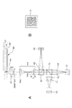
<2.ディスクドライブ装置の構成例>
<3.記録再生方式>
<4.狭トラックピッチによる高密度化>
<5.トラッキング手法>
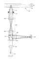
<6.光学系構成例>
<7.変形例>
Hereinafter, embodiments of the present disclosure will be described in the following order.
<1. Recording medium of embodiment>
<2. Configuration example of disk drive device>
<3. Recording / playback system>
<4. High density with narrow track pitch>
<5. Tracking method>
<6. Example of optical system configuration>
<7. Modification>
<1.実施の形態の記録媒体>
実施の形態の記録媒体は、例えばCD、DVD、ブルーレイディスク(BD)等のように、例えば直径12cmの光ディスクであるとする。
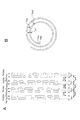
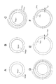
図1は、実施の形態の記録媒体(光ディスク)90の断面構造の例を模式的に示している。
<1. Recording medium of embodiment>
The recording medium according to the embodiment is assumed to be an optical disk having a diameter of 12 cm, such as a CD, a DVD, a Blu-ray disc (BD), and the like.
FIG. 1 schematically shows an example of a cross-sectional structure of a recording medium (optical disc) 90 according to the embodiment.
図1Aは、光ディスク90が、基板93、バルク層91、カバー層92を有する構造例を示している。バルク層91内の所定の深さ位置に記録層(レイヤーL0)が形成されている。なお「深さ」とは厚み方向にみてカバー層92の表面からの距離をいう。この図1Aの構造は、記録層が単層のシングルレイヤーディスクの例である。
カバー層92の表面側がレーザ光の入射面となる。レーザ光はカバー層92の表面側から入射され、レイヤーL0に合焦されて、スポットを形成し、記録又は再生が行われる。
FIG. 1A shows a structural example in which the
The surface side of the
図1Bは、バルク層に多数の記録層(レイヤーL0・・・Ln)が形成される多層ディスクの例を示している。この場合、レーザ光はカバー層92の表面側から入射され、目的とするレイヤーに合焦されてスポットを形成し、記録又は再生が行われる。
FIG. 1B shows an example of a multi-layer disc in which a large number of recording layers (layers L0... Ln) are formed in the bulk layer. In this case, the laser beam is incident from the surface side of the
図1Cは、リファレンス面RLを設けた例である。リファレンス面RLは、例えばバルク層91とカバー層92の接合面部分に形成される。
このリファレンス面RLは、ランド/グルーブ構造を有する。例えばグルーブがスパイラル状に形成され、バルク層91内のレイヤーL0・・・Lnに形成される情報記録トラックの記録の際のトラッキングのガイドとなる。
なおリファレンス面RLはグルーブではなくピット列としてもよい。またグルーブ又はピット列をアドレス情報に基づいてウォブリング(蛇行)させ絶対位置情報を記録するようにしても良い。
FIG. 1C is an example in which a reference surface RL is provided. The reference surface RL is formed, for example, at the joint surface portion between the
The reference surface RL has a land / groove structure. For example, the groove is formed in a spiral shape, and serves as a tracking guide when recording information recording tracks formed in the layers L0 to Ln in the
The reference surface RL may be a pit row instead of a groove. Further, the absolute position information may be recorded by wobbling (meandering) the groove or pit row based on the address information.
図1の各例はあくまでも一例である。実施の形態の光ディスク90の層構造としては、これらの構造以外の例も考えられる。
シングルレイヤーの場合、図1Aのようなバルク層91を設ける必要は必ずしもない。例えば基板93上にカバー層92を形成し、基板93とカバー層92の接合面にレイヤーL0を形成してもよい。
また図1B、図1Cのようなマルチレイヤーの多層ディスクの場合に、バルク層91を積層膜構造とし、各積層膜上に各レイヤーL0・・・Lnを形成するようにしてもよい。
なお、以下では、記録層としてのシングルレイヤーの場合のレイヤーL0や、マルチレイヤーのレイヤーL0・・・Lnを総称する場合、「レイヤーL」と表記する。
Each example in FIG. 1 is merely an example. As the layer structure of the
In the case of a single layer, it is not always necessary to provide the
1B and 1C, the
In the following, the layer L0 in the case of a single layer as a recording layer and the multi-layers L0... Ln are collectively referred to as “layer L”.
実施の形態の光ディスク90としては、再生専用ディスクや記録可能型ディスク(ライトワンスディスクやリライタブルディスク)が想定される。
再生専用ディスクの場合、各レイヤーLにエンボスピット列が形成される。エンボスピット列は各レイヤーL用のディスク原盤から形成されたスタンパを用いたスタンピングにより形成されればよい。
As the
In the case of a read-only disc, an emboss pit row is formed in each layer L. The emboss pit row may be formed by stamping using a stamper formed from the disk master for each layer L.
記録可能型ディスクとしての光ディスク90の場合は、記録装置により回転駆動された状態にて記録用のレーザ光照射が行われてレイヤーLに記録情報に応じたマーク列が形成される。マークとしては、相変化マーク、色素変化マーク、干渉縞マーク、ボイド(空孔)マーク、屈折率変化マークなどが想定される。
In the case of the
光ディスク90に対する再生時には、再生装置により光ディスク90が回転駆動された状態にて、再生用のレーザ光が、再生する目的のレイヤーLに照射される。そしてそのレイヤーLに形成されたピット列又はマーク列に応じた反射光情報が検出され、データが再生される。
At the time of reproduction with respect to the
ここで本実施の形態の光ディスク90は、レイヤーLにおいてマーク列(又はエンボスピット列)により形成される情報記録トラックの狭トラックピッチ化により、高密度記録を行うことで、大容量化を図るものである。
Here, the
図2,図3,図4に情報記録トラックの例を示す。
図2は2重スパイラル(ダブルスパイラル)構造でトラックが形成される例を示している。なお、「情報記録トラック」とは、スパイラル状の連続したマーク列(又はエンボスピット列)で形成されるトラック構造のことをいい、単に「トラック」というときは、1周回のトラック部分を指すものとする。
2, 3 and 4 show examples of information recording tracks.
FIG. 2 shows an example in which a track is formed with a double spiral structure. The “information recording track” means a track structure formed by spiral continuous mark rows (or embossed pit rows), and simply “track” means a track portion of one round. And
図2Aは、レイヤーLにマーク列(又はエンボスピット列:以下、マーク列の例で説明する)で形成される情報記録トラックを模式的に示している。
また図2Bは、マーク列で形成される情報記録トラックを、ディスク平面方向に見たときのトラック軌道を模式的に示している。
FIG. 2A schematically shows an information recording track formed on the layer L with a mark row (or an embossed pit row, which will be described below as an example of the mark row).
FIG. 2B schematically shows a track trajectory when the information recording track formed by the mark row is viewed in the disk plane direction.
図2Bに示すように、情報記録トラックは、2つの独立したトラック軌道TKa、TKbがそれぞれスパイラル状に形成された、2重スパイラル構造となっている。
図2Aは、この2重スパイラル構造の情報記録トラックにおける半径方向に隣接する8個のトラック(TK1〜TK8)を拡大したものである。なお、各トラックTK1〜TK8には、符号末尾に(a)又は(b)を付しているが、(a)を付したトラックTK1,TK3,TK5,TK7は、トラック軌道TKa上のトラック、(b)を付したトラックTK2,TK4,TK6,TK8は、トラック軌道TKb上のトラックであるとしている。
As shown in FIG. 2B, the information recording track has a double spiral structure in which two independent track orbits TKa and TKb are formed in a spiral shape.
FIG. 2A is an enlarged view of eight tracks (TK1 to TK8) adjacent in the radial direction in the information recording track having the double spiral structure. Each track TK1 to TK8 has (a) or (b) added to the end of the code. Tracks TK2, TK4, TK6, and TK8 marked with (b) are assumed to be tracks on the track trajectory TKb.
この情報記録トラックは、トラック軌道TKa上のトラックとトラック軌道TKb上のトラックの、2つの隣接するトラックでトラック群を形成している。例えばトラックTK1,TK2がトラック群、トラックTK3,TK4がトラック群というようになる。
ここでトラック群とは、トラックピッチTp1で隣接する隣接トラックの組をいう。そしてトラックピッチTp1とは、照射するレーザ光の波長と照射光学系のNAから規定される光学的カットオフに相当するトラックピッチよりも短い第1のトラックピッチのことである。
例えばトラックTK1,TK2間は、光学的カットオフ相当より短いトラックピッチTp1となっている。
This information recording track forms a track group with two adjacent tracks, a track on the track orbit TKa and a track on the track orbit TKb. For example, the tracks TK1 and TK2 are a track group, and the tracks TK3 and TK4 are a track group.
Here, the track group refers to a set of adjacent tracks adjacent at a track pitch Tp1. The track pitch Tp1 is a first track pitch that is shorter than the track pitch corresponding to the optical cutoff defined by the wavelength of the laser beam to be irradiated and the NA of the irradiation optical system.
For example, the track pitch Tp1 between the tracks TK1 and TK2 is shorter than that corresponding to the optical cutoff.
また、隣接するトラック群どうしで隣り合うことになるトラックは、トラックピッチTp2で離間している。トラックピッチTp2は、例えば光学的カットオフに相当するトラックピッチよりも長い第2のトラックピッチである。
例えばトラックTK2,TK3間や、トラックTK4,TK5間などが、隣接するトラック群どうしの間で隣り合うトラックとなり、これらのピッチがトラックピッチTp2となっている。
トラック群どうしのピッチをトラック群ピッチTpGとして示している。トラックピッチTp2が光学的カットオフに相当するトラックピッチよりも長い場合、必然的にトラック群ピッチTpGは、光学的カットオフに相当するトラックピッチよりも長いものとなる。
In addition, tracks that are adjacent to each other between adjacent track groups are separated by a track pitch Tp2. The track pitch Tp2 is, for example, a second track pitch that is longer than the track pitch corresponding to the optical cutoff.
For example, the tracks TK2 and TK3 and the tracks TK4 and TK5 are adjacent to each other between adjacent track groups, and these pitches are the track pitch Tp2.
The pitch between the track groups is shown as a track group pitch TpG. When the track pitch Tp2 is longer than the track pitch corresponding to the optical cutoff, the track group pitch TpG inevitably becomes longer than the track pitch corresponding to the optical cutoff.
即ちこの図2の情報記録トラックは、光学的カットオフに相当するトラックピッチよりも短いトラックピッチTp1で2つのトラックが隣接するトラック群が形成されていると共に、隣接するトラック群どうしのトラック群ピッチTpGは、光学的カットオフに相当するトラックピッチよりも長くされている。
そして情報記録トラックは、図2Bのように独立した2本のトラック軌道TKa,TKbがそれぞれスパイラル状に形成されるダブルスパイラル構造とされており、トラック軌道TKa,TKbにより光学的カットオフに相当するトラックピッチよりも短いトラックピッチTp1のトラック群が形成される。また2重スパイラル構造で周回されて隣接する隣接する上記トラック群どうしのトラック群ピッチTpGが、光学的カットオフに相当するトラックピッチよりも長くされている。
That is, in the information recording track of FIG. 2, a track group in which two tracks are adjacent is formed at a track pitch Tp1 shorter than the track pitch corresponding to the optical cut-off, and the track group pitch between the adjacent track groups is formed. TpG is longer than the track pitch corresponding to the optical cutoff.
The information recording track has a double spiral structure in which two independent track tracks TKa and TKb are formed in a spiral shape as shown in FIG. 2B, and corresponds to an optical cutoff by the track tracks TKa and TKb. A track group having a track pitch Tp1 shorter than the track pitch is formed. Further, the track group pitch TpG between the adjacent track groups which are circulated by the double spiral structure is made longer than the track pitch corresponding to the optical cutoff.
トラックピッチTp1、TpGについては後に詳述するが、光学的カットオフ相当よりも短いトラックピッチTp1で隣接するトラックでは、レーザ照射時の反射光情報として、RF信号、SUM信号、プッシュプル信号等が良好に得られない。
本実施の形態では、このようなトラックピッチTp1で隣接する複数のトラックによるトラック群が、光学的カットオフ相当よりも長いトラック群ピッチTpGであるという周期構造を採ることで、トラッキング制御可能な信号を抽出できるようにするものである。
なお、トラックピッチTp2については、光学的カットオフ相当よりも短いものであってもよい。即ち、あくまで、トラック群ピッチTpGが、光学的カットオフ相当のピッチよりも長くされていれば良い。
例えばこの2重スパイラル構造の場合、トラック群ピッチTpG=Tp1+Tp2となる。従って、トラックピッチTp1、Tp2がいずれも光学的カットオフ相当よりも短くても、Tp1+Tp2が光学的カットオフ相当よりも長ければ良い。トラックピッチTp2を光学的カットオフ相当よりも短くすれば、それだけ高密度化に有利である。一方、トラックピッチTp2が光学的カットオフ相当よりも長ければ、トラッキングエラー信号TEの抽出や、再生時のクロストーク、また記録時のクロスライトの点で有利となる。
The track pitches Tp1 and TpG will be described in detail later. On the adjacent tracks with a track pitch Tp1 shorter than that corresponding to the optical cutoff, RF signals, SUM signals, push-pull signals, etc. are reflected as reflected light information at the time of laser irradiation. It cannot be obtained well.
In the present embodiment, a signal capable of tracking control is obtained by adopting a periodic structure in which a track group formed by a plurality of tracks adjacent to each other with such a track pitch Tp1 has a track group pitch TpG longer than that corresponding to the optical cutoff. Can be extracted.
The track pitch Tp2 may be shorter than that corresponding to the optical cutoff. That is, it is only necessary that the track group pitch TpG is longer than the pitch corresponding to the optical cutoff.
For example, in the case of this double spiral structure, the track group pitch TpG = Tp1 + Tp2. Therefore, even if the track pitches Tp1 and Tp2 are both shorter than the optical cutoff, it is only necessary that Tp1 + Tp2 is longer than the optical cutoff. If the track pitch Tp2 is made shorter than that corresponding to the optical cut-off, it is advantageous for higher density. On the other hand, if the track pitch Tp2 is longer than that corresponding to the optical cutoff, it is advantageous in terms of extraction of the tracking error signal TE, crosstalk during reproduction, and crosswrite during recording.
実施の形態のディスク90の情報記録トラックとしては、図2の2重スパイラル構造以外に、3重スパイラル構造、4重スパイラル構造等、より多重のスパイラル構造としてもよい。
The information recording track of the
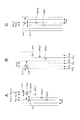
図3A、図3Bは、図2A、図2Bと同様の形式で、情報記録トラックの構造を模式的に示している。
図3Bに示すように、情報記録トラックは、3つの独立したトラック軌道TKa、TKb、TKcがそれぞれスパイラル状に形成された、3重スパイラル構造となっている。
図3Aは、この3重スパイラル構造の情報記録トラックにおける半径方向に隣接する9個のトラック(TK1〜TK9)を拡大したものである。なお、各トラックTK1〜TK9の符号末尾の(a)(b)(c)は、そのトラックが含まれるトラック軌道TKa、TKb、TKcを示している。
3A and 3B schematically show the structure of the information recording track in the same format as FIGS. 2A and 2B.
As shown in FIG. 3B, the information recording track has a triple spiral structure in which three independent track orbits TKa, TKb, and TKc are formed in a spiral shape.
FIG. 3A is an enlarged view of nine tracks (TK1 to TK9) adjacent in the radial direction in the information recording track of the triple spiral structure. Note that (a), (b), and (c) at the end of the codes of the tracks TK1 to TK9 indicate the track trajectories TKa, TKb, and TKc in which the tracks are included.
この情報記録トラックは、トラック軌道TKa上のトラックと、トラック軌道TKb上のトラックと、トラック軌道TKcのトラックの3つの隣接するトラックでトラック群を形成している。例えばトラックTK1,TK2,TK3がトラック群、トラックTK4,TK5、TK6がトラック群というようになる。
そしてトラック群内のトラックは、トラックピッチTp1で隣接している。さらに、隣接するトラック群どうしはトラック群ピッチTpG2で離間している。
This information recording track forms a track group of three adjacent tracks, a track on the track orbit TKa, a track on the track orbit TKb, and a track on the track orbit TKc. For example, tracks TK1, TK2, and TK3 are track groups, and tracks TK4, TK5, and TK6 are track groups.
The tracks in the track group are adjacent at a track pitch Tp1. Further, adjacent track groups are separated by a track group pitch TpG2.
即ちこの図3の情報記録トラックは、光学的カットオフに相当するトラックピッチよりも短いトラックピッチTp1で3つのトラックが隣接するトラック群が形成されていると共に、隣接するトラック群どうしのトラック群ピッチTpGは、光学的カットオフに相当するトラックピッチよりも長くされている。
そして情報記録トラックは、図3Bのように独立した3本のトラック軌道TKa,TKb、TKcがそれぞれスパイラル状に形成される3重(トリプル)スパイラル構造とされており、トラック軌道TKa,TKb,TKcによりトラックピッチTp1のトラック群が形成される。また3重スパイラル構造で周回されて隣接するトラック群どうしの間のトラック群ピッチTpGが、光学的カットオフに相当するトラックピッチよりも長くされている。
この3重スパイラル構造の場合、トラック群ピッチTpG=Tp1+Tp2+Tp1となる。
従って、隣接するトラック群どうしで隣り合うことになるトラックどうし(例えばトラックTK3,TK4)のトラックピッチTp2を、光学的カットオフに相当するトラックピッチよりも長くすれば、必然的にトラック群ピッチTpGは、光学的カットオフに相当するトラックピッチよりも長いものとなる。
もちろんトラックピッチTp2は、光学的カットオフに相当するトラックピッチよりも短くしても良い。
That is, in the information recording track of FIG. 3, a track group in which three tracks are adjacent is formed at a track pitch Tp1 shorter than the track pitch corresponding to the optical cut-off, and the track group pitch between the adjacent track groups is formed. TpG is longer than the track pitch corresponding to the optical cutoff.
The information recording track has a triple (triple) spiral structure in which three independent track tracks TKa, TKb, and TKc are formed in a spiral shape as shown in FIG. 3B. The track tracks TKa, TKb, and TKc Thus, a track group having a track pitch Tp1 is formed. In addition, the track group pitch TpG between adjacent track groups that are circulated in a triple spiral structure is longer than the track pitch corresponding to the optical cutoff.
In the case of this triple spiral structure, the track group pitch TpG = Tp1 + Tp2 + Tp1.
Therefore, if the track pitch Tp2 of adjacent tracks (for example, tracks TK3 and TK4) between adjacent track groups is made longer than the track pitch corresponding to the optical cutoff, the track group pitch TpG is inevitably generated. Is longer than the track pitch corresponding to the optical cutoff.
Of course, the track pitch Tp2 may be shorter than the track pitch corresponding to the optical cutoff.
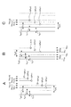
図4A、図4Bも、図2A、図2Bと同様の形式で、情報記録トラックの構造を模式的に示している。
図4Bに示すように、情報記録トラックは、4つの独立したトラック軌道TKa、TKb、TKc、TKdがそれぞれスパイラル状に形成された、4重スパイラル構造となっている。
図4Aは、この4重スパイラル構造の情報記録トラックにおける半径方向に隣接する12個のトラック(TK1〜TK12)を拡大したものである。なお、各トラックTK1〜TK12の符号末尾の(a)(b)(c)(d)は、そのトラックが含まれるトラック軌道TKa、TKb、TKc、TKdを示している。
4A and 4B also schematically show the structure of the information recording track in the same format as FIGS. 2A and 2B.
As shown in FIG. 4B, the information recording track has a quadruple spiral structure in which four independent track orbits TKa, TKb, TKc, and TKd are formed in a spiral shape.
FIG. 4A is an enlarged view of twelve tracks (TK1 to TK12) adjacent in the radial direction in the information recording track having the quadruple spiral structure. Note that (a), (b), (c), and (d) at the end of the codes of the tracks TK1 to TK12 indicate the track trajectories TKa, TKb, TKc, and TKd in which the tracks are included.
この情報記録トラックは、トラック軌道TKa上のトラックと、トラック軌道TKb上のトラックと、トラック軌道TKcのトラックと、トラック軌道TKdのトラックとの4つの隣接するトラックでトラック群を形成している。例えばトラックTK1,TK2,TK3,TK4がトラック群、トラックTK5,TK6、TK7、TK8がトラック群というようになる。
そしてトラック群内のトラックは、トラックピッチTp1で隣接している。さらに、隣接するトラック群どうしはトラック群ピッチTpGで離間している。
This information recording track forms a track group of four adjacent tracks including a track on the track orbit TKa, a track on the track orbit TKb, a track on the track orbit TKc, and a track on the track orbit TKd. For example, tracks TK1, TK2, TK3, and TK4 are track groups, and tracks TK5, TK6, TK7, and TK8 are track groups.
The tracks in the track group are adjacent at a track pitch Tp1. Further, adjacent track groups are separated by a track group pitch TpG.
即ちこの図4の情報記録トラックは、光学的カットオフに相当するトラックピッチよりも短いトラックピッチTp1で4つのトラックが隣接するトラック群が形成されていると共に、隣接するトラック群どうしのトラック群ピッチTpGは、光学的カットオフに相当するトラックピッチよりも長くされている。
そして情報記録トラックは、図4Bのように独立した4本のトラック軌道TKa,TKb、TKc、TKdがそれぞれスパイラル状に形成される4重スパイラル構造とされており、トラック軌道TKa,TKb,TKc,TKdによりトラックピッチTp1のトラック群が形成される。また4重スパイラル構造で周回されて隣接するトラック群どうしのピッチが光学的カットオフに相当するトラックピッチよりも長いトラック群ピッチTpGとなる。
この4重スパイラル構造の場合、トラック群ピッチTpG=Tp1+Tp1+Tp1+Tp2となる。
従って、隣接するトラック群どうしで隣り合うことになるトラックどうし(例えばトラックTK4,TK5)のトラックピッチTp2を、光学的カットオフに相当するトラックピッチよりも長くすれば、必然的にトラック群ピッチTpGは、光学的カットオフに相当するトラックピッチよりも長いものとなる。
もちろんトラックピッチTp2は、光学的カットオフに相当するトラックピッチよりも短くしても良い。
That is, in the information recording track of FIG. 4, a track group in which four tracks are adjacent is formed at a track pitch Tp1 shorter than the track pitch corresponding to the optical cutoff, and the track group pitch between the adjacent track groups is formed. TpG is longer than the track pitch corresponding to the optical cutoff.
The information recording track has a quadruple spiral structure in which four independent track tracks TKa, TKb, TKc, and TKd are formed in a spiral shape as shown in FIG. 4B, and the track tracks TKa, TKb, TKc, A track group having a track pitch Tp1 is formed by TKd. Further, the pitch between adjacent track groups that are circulated by the quadruple spiral structure becomes a track group pitch TpG that is longer than the track pitch corresponding to the optical cutoff.
In the case of this quadruple spiral structure, the track group pitch TpG = Tp1 + Tp1 + Tp1 + Tp2.
Therefore, if the track pitch Tp2 of adjacent tracks (for example, tracks TK4 and TK5) between adjacent track groups is made longer than the track pitch corresponding to the optical cutoff, the track group pitch TpG is inevitably generated. Is longer than the track pitch corresponding to the optical cutoff.
Of course, the track pitch Tp2 may be shorter than the track pitch corresponding to the optical cutoff.
以上、2重スパイラル構造、3重スパイラル構造、4重スパイラル構造の例を示したが、5重スパイラル構造以上の多重スパイラル構造も同様に考えられる。
The example of the double spiral structure, the triple spiral structure, and the quadruple spiral structure has been described above, but a multiple spiral structure of a five-fold spiral structure or more is also conceivable.
<2.ディスクドライブ装置の構成例>
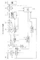
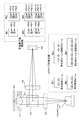
本実施の形態のディスクドライブ装置(記録再生装置)の構成を図5により説明する。
実施の形態のディスクドライブ装置は、上述したような情報記録トラック構造を有する実施の形態のディスク90としての再生専用ディスクや記録可能型ディスク(ライトワンスディスクやリライタブルディスク)に対応して再生や記録を行うことができるものとする。
<2. Configuration example of disk drive device>
The configuration of the disk drive device (recording / reproducing device) of this embodiment will be described with reference to FIG.
The disk drive apparatus according to the embodiment reproduces or records in correspondence with a reproduction-only disk or a recordable disk (write-once disk or rewritable disk) as the
実施の形態の光ディスク90は、ディスクドライブ装置に装填されると図示しないターンテーブルに積載され、記録/再生動作時においてスピンドルモータ2によって一定線速度(CLV)又は一定角速度(CAV)で回転駆動される。
そして再生時には光ピックアップ(光学ヘッド)1によって光ディスク90上の情報記録トラックに記録されたマーク情報(又はエンボスピット情報)の読出が行われる。
また光ディスク90に対してのデータ記録時には、光ピックアップ1によって光ディスク90上のトラックに、ユーザーデータがマーク列として記録される。
The
During reproduction, the mark information (or embossed pit information) recorded on the information recording track on the
At the time of data recording on the
光ピックアップ1内には、レーザ光源となるレーザダイオードや、反射光を検出するためのフォトディテクタ、レーザ光の出力端となる対物レンズ、対物レンズを介してディスク記録面にレーザ光を照射し、またその反射光をフォトディテクタに導く光学系等が形成される。
光ピックアップ1内において対物レンズは二軸機構によってトラッキング方向及びフォーカス方向に移動可能に保持されている。
また光ピックアップ1全体はスレッド機構3によりディスク半径方向に移動可能とされている。
また光ピックアップ1におけるレーザダイオードはレーザドライバ13によって駆動電流が流されることでレーザ発光駆動される。
In the
In the
The entire
The laser diode in the
ディスク90からの反射光情報はフォトディテクタによって検出され、受光光量に応じた電気信号とされてマトリクス回路4に供給される。
マトリクス回路4には、フォトディテクタとしての複数の受光素子からの出力電流に対応して電流電圧変換回路、マトリクス演算/増幅回路等を備え、マトリクス演算処理により必要な信号を生成する。
例えば再生データに相当する再生情報信号(RF信号)、サーボ制御のためのフォーカスエラー信号、トラッキングエラー信号などを生成する。
マトリクス回路4から出力される再生情報信号は、クロストークキャンセル回路6を介してデータ検出処理部5へ供給される。またマトリクス回路4から出力されるフォーカスエラー信号及びトラッキングエラー信号は光学ブロックサーボ回路11へ供給される。
Reflected light information from the
The
For example, a reproduction information signal (RF signal) corresponding to reproduction data, a focus error signal for servo control, a tracking error signal, and the like are generated.
The reproduction information signal output from the
クロストークキャンセル回路6は、RF信号に対してクロストークキャンセル処理を行う。本実施の形態の光ディスク90は、図2,図3,図4で例示したように、非常に狭いトラックピッチTp1で隣接するトラックを有する。トラックピッチが狭くなるほど、再生時に隣接トラックのクロストーク成分の混入が多くなる。そこで、クロストークキャンセル回路6を設け、隣接するトラックのRF信号成分をキャンセルする処理を行うようにする。
なお、光ディスク90上の情報記録トラックのフォーマット(トラックピッチ等)によっては、クロストークキャンセル回路6は設けないで良い場合もある。
またクロストークキャンセル回路6は、トラッキングエラー信号の生成のためにマトリクス回路の動作を制御する場合もある。
The crosstalk cancellation circuit 6 performs a crosstalk cancellation process on the RF signal. The
Depending on the format of the information recording track on the optical disc 90 (track pitch, etc.), the crosstalk cancel circuit 6 may not be provided.
Further, the crosstalk cancel circuit 6 may control the operation of the matrix circuit in order to generate a tracking error signal.
データ検出処理部5は、再生情報信号の2値化処理を行う。
例えばデータ検出処理部5では、RF信号のA/D変換処理、PLLによる再生クロック生成処理、PR(Partial Response)等化処理、ビタビ復号(最尤復号)等を行い、パーシャルレスポンス最尤復号処理(PRML検出方式:Partial Response Maximum Likelihood検出方式)により、2値データ列を得る。
そしてデータ検出処理部5は、光ディスク90から読み出した情報としての2値データ列を、後段のエンコード/デコード部7に供給する。
The data
For example, the data
Then, the data
エンコード/デコード部7は、再生時おける再生データの復調と、記録時における記録データの変調処理を行う。即ち、再生時にはデータ復調、デインターリーブ、ECCデコード、アドレスデコード等を行い、また記録時にはECCエンコード、インターリーブ、データ変調等を行う。
再生時においては、上記データ検出処理部5で復号された2値データ列がエンコード/デコード部7に供給される。エンコード/デコード部7では上記2値データ列に対する復調処理を行い、光ディスク90からの再生データを得る。
例えば光ディスク90に記録されたデータが、RLL(1,7)PP変調等のランレングスリミテッドコード変調(RLL;Run Length Limited、PP:Parity preserve/Prohibit rmtr(repeated minimum transition runlength))が施されたものであった場合、このようなデータ変調に対しての復調処理を行い、またECCデコード処理でエラー訂正を行って、光ディスク90からの再生データを得る。
エンコード/デコード部7で再生データにまでデコードされたデータは、ホストインターフェース8に転送され、システムコントローラ10の指示に基づいてホスト機器100に転送される。ホスト機器100とは、例えばコンピュータ装置やAV(Audio-Visual)システム機器などである。
The encode / decode unit 7 performs demodulation of reproduction data during reproduction and modulation processing of recording data during recording. That is, data demodulation, deinterleaving, ECC decoding, address decoding, etc. are performed during reproduction, and ECC encoding, interleaving, data modulation, etc. are performed during recording.
At the time of reproduction, the binary data string decoded by the data
For example, the data recorded on the
The data decoded to the reproduction data by the encoding / decoding unit 7 is transferred to the host interface 8 and transferred to the
記録時には、ホスト機器100から記録データが転送されてくるが、その記録データはホストインターフェース8を介してエンコード/デコード部7に供給される。
この場合エンコード/デコード部7は、記録データのエンコード処理として、エラー訂正コード付加(ECCエンコード)やインターリーブ、サブコードの付加等を行う。またこれらの処理を施したデータに対して、例えばRLL(1−7)PP方式等のランレングスリミテッドコード変調等を施す。
At the time of recording, recording data is transferred from the
In this case, the encoding / decoding unit 7 performs error correction code addition (ECC encoding), interleaving, sub-code addition, and the like as recording data encoding processing. The data subjected to these processes is subjected to run-length limited code modulation such as RLL (1-7) PP method.
エンコード/デコード部7で処理された記録データは、ライトストラテジ部14に供給される。ライトストラテジ部では、記録補償処理として、記録層の特性、レーザ光のスポット形状、記録線速度等に対するレーザ駆動パルス波形調整を行う。そして、レーザ駆動パルスをレーザドライバ13に出力する。
The recording data processed by the encoding / decoding unit 7 is supplied to the
レーザドライバ13は、記録補償処理したレーザ駆動パルスに基づいて、光ピックアップ1内のレーザダイオードに電流を流し、レーザ発光駆動を実行させる。これにより光ディスク90に、記録データに応じたマークが形成されることになる。
なお、レーザドライバ13は、いわゆるAPC回路(Auto Power Control)を備え、光ピックアップ1内に設けられたレーザパワーのモニタ用ディテクタの出力によりレーザ出力パワーをモニタしながらレーザの出力が温度などによらず一定になるように制御する。
記録時及び再生時のレーザ出力の目標値はシステムコントローラ10から与えられ、記録時及び再生時にはそれぞれレーザ出力レベルが、その目標値になるように制御する。
Based on the laser driving pulse subjected to the recording compensation process, the
The
The target value of the laser output at the time of recording and reproduction is given from the
光学ブロックサーボ回路11は、マトリクス回路4からのフォーカスエラー信号、トラッキングエラー信号から、フォーカス、トラッキング、スレッドの各種サーボドライブ信号を生成しサーボ動作を実行させる。
即ちフォーカスエラー信号、トラッキングエラー信号に応じてフォーカスドライブ信号、トラッキングドライブ信号を生成し、二軸ドライバ18により光ピックアップ1内の二軸機構のフォーカスコイル、トラッキングコイルを駆動することになる。これによってピックアップ1、マトリクス回路4、光学ブロックサーボ回路11、二軸ドライバ18、二軸機構によるトラッキングサーボループ及びフォーカスサーボループが形成される。
また光学ブロックサーボ回路11は、システムコントローラ10からのトラックジャンプ指令に応じて、トラッキングサーボループをオフとし、ジャンプドライブ信号を出力することで、トラックジャンプ動作を実行させる。
また光学ブロックサーボ回路11は、トラッキングエラー信号の低域成分として得られるスレッドエラー信号や、システムコントローラ10からのアクセス実行制御などに基づいてスレッドドライブ信号を生成し、スレッドドライバ19によりスレッド機構3を駆動する。スレッド機構3には、図示しないが、ピックアップ1を保持するメインシャフト、スレッドモータ、伝達ギア等による機構を有し、スレッドドライブ信号に応じてスレッドモータを駆動することで、光ピックアップ1の所要のスライド移動が行なわれる。
The optical
That is, a focus drive signal and a tracking drive signal are generated according to the focus error signal and the tracking error signal, and the
The optical
The optical
スピンドルサーボ回路12はスピンドルモータ2をCLV回転させる制御を行う。
スピンドルサーボ回路12は、RF信号に対するPLL処理で生成されるクロック等として現在のスピンドルモータ2の回転速度情報として得、これを所定のCLV(又はCAV)基準速度情報と比較することで、スピンドルエラー信号を生成する。
そしてスピンドルサーボ回路12は、スピンドルエラー信号に応じて生成したスピンドルドライブ信号を出力し、スピンドルドライバ17によりスピンドルモータ2のCLV回転又はCAV回転を実行させる。
またスピンドルサーボ回路12は、システムコントローラ10からのスピンドルキック/ブレーキ制御信号に応じてスピンドルドライブ信号を発生させ、スピンドルモータ2の起動、停止、加速、減速などの動作も実行させる。
なおスピンドルモータ2には、例えばFG(Freqency Generator)やPG(Pulse Generator)が設けられ、その出力がシステムコントローラ10に供給される。これによりシステムコントローラ10はスピンドルモータ2の回転情報(回転速度、回転角度位置)を認識できる。
The
The
The
Further, the
The
以上のようなサーボ系及び記録再生系の各種動作はマイクロコンピュータによって形成されたシステムコントローラ10により制御される。
システムコントローラ10は、ホストインターフェース8を介して与えられるホスト機器100からのコマンドに応じて各種処理を実行する。
例えばホスト機器100から書込命令(ライトコマンド)が出されると、システムコントローラ10は、まず書き込むべき論理的もしくは物理的空間的なアドレスにピックアップ1を移動させる。そしてエンコード/デコード部7により、ホスト機器100から転送されてきたデータ(例えばビデオデータやオーディオデータ等)について上述したようにエンコード処理を実行させる。そして上記のようにエンコードされたデータに応じてレーザドライバ13がレーザ発光駆動することで記録が実行される。
Various operations of the servo system and the recording / reproducing system as described above are controlled by a
The
For example, when a write command (write command) is issued from the
また例えばホスト機器100から、光ディスク90に記録されている或るデータの転送を求めるリードコマンドが供給された場合は、システムコントローラ10はまず指示されたアドレスを目的としてシーク動作制御を行う。即ち光学ブロックサーボ回路11に指令を出し、シークコマンドにより指定されたアドレスをターゲットとする光ピックアップ1のアクセス動作を実行させる。
その後、その指示されたデータ区間のデータをホスト機器100に転送するために必要な動作制御を行う。即ちディスク90からのデータ読出を行い、データ検出処理部5、エンコード/デコード部7における再生処理を実行させ、要求されたデータを転送する。
Further, for example, when a read command for requesting transfer of certain data recorded on the
Thereafter, operation control necessary for transferring the data in the designated data section to the
なお図1の例は、ホスト機器100に接続されるディスクドライブ装置として説明したが、ディスクドライブ装置としては他の機器に接続されない形態もあり得る。その場合は、操作部や表示部が設けられたり、データ入出力のインターフェース部位の構成が、図1とは異なるものとなる。つまり、ユーザーの操作に応じて記録や再生が行われるとともに、各種データの入出力のための端子部が形成されればよい。もちろんディスクドライブ装置の構成例としては他にも多様に考えられる。
Although the example of FIG. 1 has been described as a disk drive device connected to the
<3.記録再生方式>
実施の形態の記録再生方式としての各種の例を説明する。
図6は、情報記録トラックを図2のように2重スパイラル構造とする場合の記録動作例と再生動作例を示している。各図では、情報記録トラックを実線または破線で示す。
<3. Recording / playback system>
Various examples as the recording / reproducing system of the embodiment will be described.
FIG. 6 shows a recording operation example and a reproduction operation example when the information recording track has a double spiral structure as shown in FIG. In each figure, the information recording track is indicated by a solid line or a broken line.
図6Aは、再生パワーのレーザによる2つの再生用レーザスポットSPp1、SPp2と、記録パワーのレーザによる2つの記録用レーザスポットSPr1、SPr2を光ディスク90のレイヤーLに照射する例である。
特には、2重スパイラルのトラック軌道を同時に形成していく例である。
FIG. 6A shows an example in which the layer L of the
In particular, this is an example in which double spiral track tracks are formed simultaneously.
再生用レーザスポットSPp1、SPp2はトラッキングエラー信号を検出するためのサーボ用のレーザ光とする。そして再生用レーザスポットSPp1、SPp2が、2重スパイラルのトラックTKx、TKx+1のトラック群に対してトレースするようにトラッキング制御を行う。例えばトラックTKx、TKx+1の中央にトラッキング制御されるようにする。
なお、トラックTKx、TKx+1の間のトラックピッチTp1は光学的カットオフ相当より短いトラックピッチであるが、2つの再生用レーザスポットSPp1、SPp2の各反射光情報により得られる各ラジアルコントラスト信号の差分信号としてトラッキングエラー信号を得ることができる。これについては後述する。
The reproduction laser spots SPp1 and SPp2 are servo laser beams for detecting a tracking error signal. Then, the tracking control is performed so that the reproduction laser spots SPp1 and SPp2 trace the double spiral tracks TKx and TKx + 1. For example, tracking control is performed at the center of the tracks TKx and TKx + 1.
The track pitch Tp1 between the tracks TKx and TKx + 1 is a track pitch shorter than that corresponding to the optical cut-off. A tracking error signal can be obtained. This will be described later.
この場合、光ピックアップ1は、記録用レーザスポットSPr1、SPr2は、互いにディスク半径方向にトラックピッチTp1だけ離間する状態に照射する。また再生用レーザスポットSPp2と記録用レーザスポットSPr1とは、ディスク半径方向にトラックピッチTp2だけ離間する状態に照射する。
このようにすることで、内周側のトラック群(トラックTKx、TKx+1)に対してトラッキング制御しながら、そのトラックTKx、TKx+1に沿って、記録用レーザスポットSPr1、SPr2で、外周側のトラックTKx+2,TKx+3をトラック群ピッチTpGで記録していくことが可能となる。
また、2重スパイラルのトラック軌道を同時に形成していくことで、転送レートの高い記録が実現できる。
In this case, the
In this way, while performing tracking control on the inner track group (tracks TKx, TKx + 1), along the tracks TKx, TKx + 1, the recording laser spots SPr1, SPr2 and the outer track TKx + 2 are recorded. , TKx + 3 can be recorded at the track group pitch TpG.
Also, by forming a double spiral track orbit at the same time, recording with a high transfer rate can be realized.
なお、このような記録動作は、再生用レーザスポットで内周側のトラックに対してトラッキング制御しながら、その外周側に記録用レーザスポットで記録を行うものとなる。このようなトラッキングサーボ方式を、説明上、「隣接トラッキングサーボ」ということとする。
この隣接トラッキングサーボを行う場合、まず1周回目のトラックが存在することが必要となる。
図1Cのように、リファレンス面RLが設けられ、リファレンス面RLのグルーブ等を利用できる場合は、そのリファレンス面RLのグルーブ等をガイドにして、1周目の2重スパイラルトラックを形成すればよい。その後の2周回目以降は、図6Aのように隣接トラッキングサーボで記録を実行できる。
In such a recording operation, recording is performed on the outer peripheral side with the recording laser spot while tracking control is performed on the inner peripheral side track with the reproducing laser spot. Such a tracking servo system is referred to as “adjacent tracking servo” for the sake of explanation.
When this adjacent tracking servo is performed, it is first necessary that a first round track exists.
When a reference surface RL is provided and a groove or the like of the reference surface RL can be used as shown in FIG. 1C, a double spiral track for the first round may be formed using the groove or the like of the reference surface RL as a guide. . From the second round onward, recording can be executed by the adjacent tracking servo as shown in FIG. 6A.
一方、図1A,図1Bのようにリファレンス面RLが存在しない場合は、図9A〜図9Dに示すような動作例が考えられる。
まず、図9Aのように、光ディスク90のレイヤーLに、1周の正円となるガイドトラックTKG1、TKG2を記録する。これは、光ピックアップ1がレーザスポット位置を固定したまま、光ディスク90を1回転させることで形成できる。具体的には、まずガイドトラックTKG1を形成し、その後、ガイドトラックTKG1に対して隣接トラッキングサーボをかけてガイドトラックTKG2を形成する。
このとき、同心円のガイドトラックTKG1、TKG2の間隔(トラックピッチ)はトラック群ピッチTpGと等しくなるようにする。
このようにガイドトラックTKG1,TKG2を記録したら、ガイドトラックTKG1,からTKG2Gへのトラックジャンプがちょうど1回転となるようなジャンプパルスを学習する。即ち図9Bに破線で示す軌道を形成するジャンプパルスである。
そして、学習したジャンプパルスを用いて、図9Cのように1周回目の2重スパイラルトラックを記録する。学習したジャンプパルスを用いることで、この2重スパイラルトラックTKa,TKbの1周回目は、角度位置毎に、徐々に記録用レーザスポットSPr1、SPr2が外周側にずれていくようになる。つまり2重スパイラル状の1周回分のトラックが形成できる。
その後の2周回目以降は、図6Aで述べた隣接トラッキングサーボで、図9Dに破線で示すように、2重スパイラルトラックを記録していくことができる。
On the other hand, when the reference surface RL does not exist as shown in FIGS. 1A and 1B, operation examples as shown in FIGS. 9A to 9D can be considered.
First, as shown in FIG. 9A, guide tracks TKG1 and TKG2 that are a perfect circle of one round are recorded on the layer L of the
At this time, the interval (track pitch) between the concentric guide tracks TKG1 and TKG2 is set equal to the track group pitch TpG.
When the guide tracks TKG1 and TKG2 are recorded in this way, a jump pulse is learned so that the track jump from the guide track TKG1 to TKG2G is exactly one rotation. That is, the jump pulse forms a trajectory indicated by a broken line in FIG. 9B.
Then, using the learned jump pulse, the first spiral double spiral track is recorded as shown in FIG. 9C. By using the learned jump pulse, the recording laser spots SPr1 and SPr2 gradually shift to the outer periphery side for each angular position in the first round of the double spiral tracks TKa and TKb. That is, a double spiral track for one round can be formed.
After the second round, the double spiral track can be recorded by the adjacent tracking servo described with reference to FIG. 6A, as indicated by the broken line in FIG. 9D.
次に図6Bは、再生パワーのレーザによる2つの再生用レーザスポットSPp1、SPp2と、記録パワーのレーザによる1つの記録用レーザスポットSPrを光ディスク90のレイヤーLに照射し、2重スパイラルの各トラック軌道を別々に形成していく例である。
Next, FIG. 6B shows a case where two reproducing laser spots SPp1 and SPp2 by a reproducing power laser and one recording laser spot SPr by a recording power laser are irradiated onto the layer L of the
まず実線のように、トラック軌道TKaのトラックがすでにスパイラル状に記録されている状態を想定する。なお、このトラック軌道TKaのトラックは、この場合、トラックピッチはTp1+Tp2となるように記録することになる。
このトラック軌道TKaのトラックが存在する状態で、破線で示すトラック軌道TKbのトラックを記録していく。
この場合、再生用レーザスポットSPp1、SPp2が、実線のトラック軌道TKaのトラックに対してトラッキング制御されるようにする。例えば再生用レーザスポットSPp1、SPp2の中間がトラック軌道TKaのトラックに位置するようにトラッキング制御する。
そして記録用レーザスポットSPrは、トラック軌道TKaのトラックから、ディスク半径方向にトラックピッチTp1だけ離間する状態に照射する。
このようにすることで、トラック軌道TKaに対して隣接して2重スパイラルを形成するトラック軌道TKbのトラックが記録されていく。
結果として、2重スパイラルで、かつトラックピッチTp1,Tp2、及びトラック群ピッチTpGを有する図2のような情報記録トラックによるデータ記録を行うことができる。
First, as shown by the solid line, it is assumed that the track of the track orbit TKa is already recorded in a spiral shape. In this case, the track on the track trajectory TKa is recorded so that the track pitch is Tp1 + Tp2.
In a state where there is a track of this track orbit TKa, a track of the track orbit TKb indicated by a broken line is recorded.
In this case, the reproduction laser spots SPp1 and SPp2 are subjected to tracking control with respect to the track of the solid track orbit TKa. For example, tracking control is performed so that the middle of the reproduction laser spots SPp1 and SPp2 is positioned on the track of the track trajectory TKa.
The recording laser spot SPr is irradiated from the track on the track trajectory TKa so as to be separated by a track pitch Tp1 in the disc radial direction.
By doing so, tracks of the track trajectory TKb forming a double spiral adjacent to the track trajectory TKa are recorded.
As a result, it is possible to perform data recording by an information recording track as shown in FIG. 2 having a double spiral, track pitches Tp1, Tp2, and track group pitch TpG.
なお、以上のようにこの記録動作も隣接トラッキングサーボを行うものとなるが、この場合、2重スパイラルのトラックを形成する前に、最初にトラックピッチがTp1+Tp2となるトラック軌道TKaのトラックを記録することとなる。
図1Cのように、リファレンス面RLが設けられ、リファレンス面RLのグルーブ等を利用できる場合は、そのリファレンス面RLのグルーブ等をガイドにして、図9EのようにトラックピッチTp1+Tp2のトラック軌道TKaのスパイラルトラックを形成すればよい。その後、トラック軌道TKbのスパイラルトラックの記録は、図6Bのように隣接トラッキングサーボを行うことで、図9Fの破線で示すように実行できる。
As described above, this recording operation also performs the adjacent tracking servo. In this case, before forming the double spiral track, the track of the track trajectory TKa with the track pitch Tp1 + Tp2 is first recorded. It will be.
When a reference surface RL is provided as shown in FIG. 1C and a groove or the like of the reference surface RL can be used, the groove or the like of the reference surface RL is used as a guide, and the track orbit TKa of the track pitch Tp1 + Tp2 as shown in FIG. A spiral track may be formed. Thereafter, the recording of the spiral track of the track trajectory TKb can be executed as shown by the broken line in FIG. 9F by performing the adjacent tracking servo as shown in FIG. 6B.
一方、図1A,図1Bのようにリファレンス面RLが存在しない場合は、まず図9Aのように、光ディスク90のレイヤーLに、正円となるガイドトラックTKG1,TKG2を記録する。
このようにガイドトラックTKG1,TKG2を記録したら、図9Bで説明したようにガイドトラックTKG1,からTKG2Gへのトラックジャンプがちょうど1回転となるようなジャンプパルスを学習する。そして、学習したジャンプパルスを用いて、トラック軌道TKaの1周回目のシングルスパイラルトラックを記録する。
その後、2周回目以降は、隣接トラッキングサーボで、トラックピッチTp1+Tp2のトラックを形成していけば、図9Eのようにトラック軌道TKaとしてのスパイラルトラックが形成できることとなる。
その後、トラック軌道TKbのスパイラルトラックの記録は、図6Bのように隣接トラッキングサーボを行うことで、図9Fの破線で示すように実行できる。
On the other hand, when the reference surface RL does not exist as shown in FIGS. 1A and 1B, first, guide tracks TKG1 and TKG2 having a perfect circle are recorded on the layer L of the
When the guide tracks TKG1 and TKG2 are recorded in this way, a jump pulse is learned so that the track jump from the guide track TKG1 to TKG2G is exactly one rotation as described in FIG. 9B. Then, the single spiral track of the first round of the track trajectory TKa is recorded using the learned jump pulse.
After that, in the second and subsequent rounds, if tracks with a track pitch Tp1 + Tp2 are formed by the adjacent tracking servo, a spiral track as the track trajectory TKa can be formed as shown in FIG. 9E.
Thereafter, the recording of the spiral track of the track trajectory TKb can be executed as shown by the broken line in FIG. 9F by performing the adjacent tracking servo as shown in FIG. 6B.
続いて、図6Cで再生動作を説明する。
これは図6Aまたは図6Bのような記録動作(または再生専用ディスク)で、図2のような2重スパイラル構造の情報記録トラックが形成されている場合の再生動作例である。
この場合、再生パワーのレーザによる2つの再生用レーザスポットSPp1、SPp2を光ディスク90のレイヤーLに照射する。再生用レーザスポットSPp1、SPp2は互いにディスク半径方向にトラックピッチTp1だけ離間する状態に照射する。
そして再生用レーザスポットSPp1、SPp2が、それぞれトラックピッチTp1のトラックTKx、TKx+1にオントラックするようにする。
Subsequently, the reproducing operation will be described with reference to FIG. 6C.
This is an example of the reproducing operation when the information recording track having the double spiral structure as shown in FIG. 2 is formed by the recording operation (or the reproduction-only disc) as shown in FIG. 6A or 6B.
In this case, the layer L of the
The reproducing laser spots SPp1 and SPp2 are on-tracked to the tracks TKx and TKx + 1 having the track pitch Tp1, respectively.
トラックピッチTp1は光学的カットオフ相当より短いトラックピッチであるが、2つの再生用レーザスポットSPp1、SPp2の各反射光情報により得られる各ラジアルコントラスト信号の差分信号としてトラッキングエラー信号を得ることができる。このトラッキングエラー信号を用いたトラッキングサーボ制御により、再生用レーザスポットSPp1、SPp2を、それぞれトラックTKx、TKx+1にオントラックさせる。
そして、再生用レーザスポットSPp1、SPp2の各反射光情報からトラックTKx、TKx+1のデータを再生することができる。
また、2重スパイラルのトラック軌道を同時に再生していくことで、転送レートの高い再生が実現できる。
The track pitch Tp1 is shorter than that corresponding to the optical cut-off, but a tracking error signal can be obtained as a difference signal between the radial contrast signals obtained from the reflected light information of the two reproduction laser spots SPp1 and SPp2. . The tracking laser control using the tracking error signal causes the reproduction laser spots SPp1 and SPp2 to be on-track on the tracks TKx and TKx + 1, respectively.
Then, the data of the tracks TKx and TKx + 1 can be reproduced from the reflected light information of the reproduction laser spots SPp1 and SPp2.
Also, by reproducing the double spiral track orbit at the same time, reproduction with a high transfer rate can be realized.
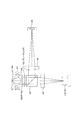
次に図7で、同じく情報記録トラックを図2のように2重スパイラル構造とする場合の記録動作例と再生動作例を説明する。この例は、サーボ用レーザスポットSPp45として、情報記録トラックの接線方向に対して略45°の角度をなす非点収差を与えたレーザスポットを照射する例である。
まず図7Aは、再生パワーのレーザによるサーボ用レーザスポットSPp45と、記録パワーのレーザによる2つの記録用レーザスポットSPr1、SPr2を光ディスク90のレイヤーLに照射する例である。特には、2重スパイラルのトラック軌道を同時に形成していく例を示している。
Next, referring to FIG. 7, an example of recording operation and an example of reproducing operation when the information recording track has a double spiral structure as shown in FIG. 2 will be described. In this example, a laser spot provided with astigmatism having an angle of approximately 45 ° with respect to the tangential direction of the information recording track is irradiated as the servo laser spot SPp45.
First, FIG. 7A shows an example in which the layer L of the
サーボ用レーザスポットSPp45を、2重スパイラルのトラックTKx、TKx+1のトラック群に対してトレースするようにトラッキング制御を行う。例えばトラックTKx、TKx+1の中央にトラッキング制御されるようにする。
なお、トラックTKx、TKx+1の間のトラックピッチTp1は光学的カットオフ相当より短いトラックピッチであるが、サーボ用レーザスポットSPp45として非点収差を与えたレーザ光を照射することで、その反射光情報としてのタンジェンシャルプッシュプル信号(トラック線方向に対して垂直方向に分割した各フォトディテクタの差分信号)としてトラッキングエラー信号を得ることができる。これについては後述する。
Tracking control is performed so that the servo laser spot SPp45 is traced with respect to the track group of the double spiral tracks TKx and TKx + 1. For example, tracking control is performed at the center of the tracks TKx and TKx + 1.
The track pitch Tp1 between the tracks TKx and TKx + 1 is a track pitch shorter than that corresponding to the optical cut-off. By irradiating the servo laser spot SPp45 with astigmatism laser light, the reflected light information is obtained. A tracking error signal can be obtained as a tangential push-pull signal (difference signal of each photodetector divided in the direction perpendicular to the track line direction). This will be described later.
この場合、光ピックアップ1は、記録用レーザスポットSPr1、SPr2は、互いにディスク半径方向にトラックピッチTp1だけ離間する状態に照射する。またサーボ用レーザスポットSPp45と記録用レーザスポットSPr1とは、ディスク半径方向にトラックピッチTp2+(Tp1/2)だけ離間する状態に照射する。
In this case, the
このようにすることで、内周側のトラックTKx、TKx+1に対してトラッキング制御しながら、そのトラックTKx、TKx+1に沿って、記録用レーザスポットSPr1、SPr2で、外周側のトラックTKx+2,TKx+3を記録していくことが可能となる。結果として、図2のようなトラックピッチTp1、Tp2、及びトラック群ピッチTpGを有する2重スパイラル構造の情報記録トラックが形成される。
この場合、2重スパイラルのトラック軌道を同時に形成していくことで、転送レートの高い記録が実現できる。
なお、このような隣接トラッキングサーボを実行するための少なくとも1周回目のトラック群の記録の際には、リファレンス面RLを利用した記録や、図9A〜図9Dで説明した記録動作等を行えば良い。
In this way, while tracking control is performed on the inner tracks TKx and TKx + 1, the outer tracks TKx + 2 and TKx + 3 are recorded by the recording laser spots SPr1 and SPr2 along the tracks TKx and TKx + 1. It becomes possible to do. As a result, an information recording track having a double spiral structure having track pitches Tp1 and Tp2 and a track group pitch TpG as shown in FIG. 2 is formed.
In this case, recording with a high transfer rate can be realized by simultaneously forming a double spiral track orbit.
When recording at least the first track group for executing the adjacent tracking servo, the recording using the reference surface RL, the recording operation described with reference to FIGS. 9A to 9D, and the like are performed. good.
次に図7Bは、再生パワーのレーザによるサーボ用レーザスポットSPp45と、記録パワーのレーザによる1つの記録用レーザスポットSPrを光ディスク90のレイヤーLに照射し、2重スパイラルの各トラック軌道を別々に形成していく例である。
Next, in FIG. 7B, the servo laser spot SPp45 by the reproduction power laser and one recording laser spot SPr by the recording power laser are irradiated to the layer L of the
まず実線のように、トラック軌道TKaのトラックがすでにスパイラル状に記録されている状態を想定する。なお、このトラック軌道TKaのトラックは、この場合、トラックピッチはTp1+Tp2(=TpG)となるように記録する。
このトラック軌道TKaのトラックが存在する状態で、破線で示すトラック軌道TKbのトラックを記録していく。
この場合、サーボ用レーザスポットSPp45が、実線のトラック軌道TKaのトラックに対してオントラックとなるようにトラッキング制御されるようにする。
そして記録用レーザスポットSPrは、トラック軌道TKaのトラックから、ディスク半径方向にトラックピッチTp1だけ離間する状態に照射する。
このようにすることで、トラック軌道TKaに対して隣接して2重スパイラルを形成するトラック軌道TKbのトラックが記録されていく。
First, as shown by the solid line, it is assumed that the track of the track orbit TKa is already recorded in a spiral shape. In this case, the tracks on the track trajectory TKa are recorded so that the track pitch is Tp1 + Tp2 (= TpG).
In a state where there is a track of this track orbit TKa, a track of the track orbit TKb indicated by a broken line is recorded.
In this case, the tracking control is performed so that the servo laser spot SPp45 is on-track with respect to the track of the solid track orbit TKa.
The recording laser spot SPr is irradiated from the track on the track trajectory TKa so as to be separated by a track pitch Tp1 in the disc radial direction.
By doing so, tracks of the track trajectory TKb forming a double spiral adjacent to the track trajectory TKa are recorded.
結果として、2重スパイラルで、かつトラックピッチTp1,Tp2、及びトラック群ピッチTpGを有する図2のような情報記録トラックによるデータ記録を行うことができる。
なお、一方のスパイラルトラックとなるトラック軌道TKaのトラックを記録する際には、リファレンス面RLを利用した記録や、図9A、図9B、図9E、図9Fで説明した記録動作等を行えば良い。
As a result, it is possible to perform data recording by an information recording track as shown in FIG. 2 having a double spiral, track pitches Tp1, Tp2, and track group pitch TpG.
When recording the track of the track trajectory TKa to be one spiral track, the recording using the reference surface RL, the recording operation described with reference to FIGS. 9A, 9B, 9E, and 9F may be performed. .
続いて、図7Cで再生動作を説明する。
これは図7Aまたは図7Bのような記録動作(または再生専用ディスク)で、図2のような2重スパイラル構造の情報記録トラックが形成されている場合の再生動作例である。
この場合、再生パワーのレーザによるサーボ用レーザスポットSPp45と、2つの再生用レーザスポットSPp1,SPp2を光ディスク90のレイヤーLに照射する。
特に、サーボ用レーザスポットSPp45が、トラックTKx、TKx+1のトラック群に対してトレースするようにトラッキング制御を行う。例えばトラックTKx、TKx+1の中央にトラッキング制御されるようにする。
Subsequently, the reproducing operation will be described with reference to FIG. 7C.
This is an example of the reproducing operation when the information recording track having the double spiral structure as shown in FIG. 2 is formed by the recording operation (or the reproduction-only disc) as shown in FIG. 7A or 7B.
In this case, the servo laser spot SPp45 by the reproduction power laser and the two reproduction laser spots SPp1 and SPp2 are applied to the layer L of the
In particular, tracking control is performed so that the servo laser spot SPp45 traces the track group TKx,
再生用レーザスポットSPp1、SPp2については、それぞれが半径方向にトラックピッチTp1だけ離間し、かつ再生用レーザスポットSPp1はサーボ用レーザスポットSPp45とは半径方向でみてTp2+(Tp1/2)だけ離間するように照射する。
この状態で、サーボ用レーザスポットSPp45の反射光情報としてのタンジェンシャルプッシュプル信号を用いた隣接トラッキングサーボにより、再生用レーザスポットSPp1、SPp2をトラックTKx+2、TKx+3にオントラックさせる。
これにより、再生用レーザスポットSPp1、SPp2の各反射光情報からトラックTKx+2、TKx+3のデータを再生することができる。
なお、図7Dのように、サーボ用レーザスポットSPp45が、トラックTKx、TKx+1の中央をトレースするときに、再生用レーザスポットSPp1、SPp2が、それぞれトラックTKx、TKx+1にオントラックするようにして、再生用レーザスポットSPp1、SPp2の各反射光情報からトラックTKx、TKx+1のデータを再生するようにすることもできる。
図7C、図7Dのいずれの場合も、2重スパイラルのトラック軌道を同時に再生していくことで高転送レート化が実現できる。
The reproduction laser spots SPp1 and SPp2 are separated from each other by a track pitch Tp1 in the radial direction, and the reproduction laser spot SPp1 is separated from the servo laser spot SPp45 by Tp2 + (Tp1 / 2) in the radial direction. Irradiate.
In this state, the reproduction laser spots SPp1, SPp2 are on-tracked to the
Thereby, the data of the tracks TKx + 2 and TKx + 3 can be reproduced from the reflected light information of the reproduction laser spots SPp1 and SPp2.
As shown in FIG. 7D, when the servo laser spot SPp45 traces the center of the tracks TKx and TKx + 1, reproduction is performed such that the reproduction laser spots SPp1 and SPp2 are on-track to the tracks TKx and TKx + 1, respectively. The data of the tracks TKx and TKx + 1 can be reproduced from the reflected light information of the laser spots SPp1 and SPp2.
In both cases of FIGS. 7C and 7D, a high transfer rate can be realized by simultaneously reproducing the double spiral track trajectory.
次に図8で、情報記録トラックを図3のように3重スパイラル構造とする場合の記録動作例と再生動作例を説明する。
図8Aは、再生パワーのレーザによる3つの再生用レーザスポットSPp1、SPp2、SPp0と、記録パワーのレーザによる3つの記録用レーザスポットSPr1、SPr2、SPr3を光ディスク90のレイヤーLに照射する例である。
特には、3重スパイラルのトラック軌道を同時に形成していく例である。
Next, an example of recording operation and an example of reproducing operation when the information recording track has a triple spiral structure as shown in FIG. 3 will be described with reference to FIG.
FIG. 8A shows an example in which the layer L of the
In particular, this is an example of simultaneously forming a triple spiral track orbit.
再生用レーザスポットSPp1、SPp0、SPp2はトラッキングエラー信号を検出するためのサーボ用のレーザ光とする。そして再生用レーザスポットSPp1、SPp0、SPp2が、3重スパイラルのトラックTKx、TKx+1、TKx+2のトラック群に対してトレースするようにトラッキング制御を行う。
なお、トラックTKx、TKx+1、TKx+2のそれぞれの間のトラックピッチTp1は光学的カットオフ相当より短いトラックピッチであるが、3つのうち2つの再生用レーザスポットSPp1、SPp2の各反射光情報により得られる各ラジアルコントラスト信号の差分信号としてトラッキングエラー信号を得ることができる。これについては後述する。
The reproduction laser spots SPp1, SPp0, SPp2 are servo laser beams for detecting a tracking error signal. Then, tracking control is performed so that the reproduction laser spots SPp1, SPp0, and SPp2 trace the triple spiral tracks TKx, TKx + 1, and TKx + 2.
Note that the track pitch Tp1 between each of the tracks TKx, TKx + 1, and TKx + 2 is a track pitch shorter than the optical cutoff, but is obtained from the reflected light information of two of the three reproduction laser spots SPp1 and SPp2. A tracking error signal can be obtained as a differential signal of each radial contrast signal. This will be described later.
この場合、光ピックアップ1は、記録用レーザスポットSPr1、SPr2、SPr3は、互いにディスク半径方向にトラックピッチTp1だけ離間する状態に照射する。また再生用レーザスポットSPp2と記録用レーザスポットSPr1とは、ディスク半径方向にトラックピッチTp2だけ離間する状態に照射する。
In this case, the
このようにすることで、内周側のトラック群(トラックTKx、TKx+1、TKx+2)に対してトラッキング制御しながら、そのトラック群に沿って、記録用レーザスポットSPr1、SPr2、SPr3で、外周側のトラックTKx+3,TKx+4、TKx+5を記録していくことが可能となる。即ち光学的カットオフ相当より短いトラックピッチTp1のトラックを形成しつつ、光学的カットオフ相当より長いトラック群ピッチTpGのトラック群を形成していくことができる。
また3重スパイラルのトラック軌道を同時に形成していくことで、転送レートの高い記録が実現できる。
なお、このような隣接トラッキングサーボを行うために必要な、少なくとも1周回目のトラック群の記録の際には、リファレンス面RLを利用した記録や、図9A〜図9Dで説明した記録動作等を行えば良い。
In this way, while tracking control is performed on the inner track group (tracks TKx, TKx + 1, TKx + 2), along the track group, the recording laser spots SPr1, SPr2, SPr3
Further, by simultaneously forming a triple spiral track orbit, recording with a high transfer rate can be realized.
When recording at least the first track group necessary for performing such adjacent tracking servo, the recording using the reference surface RL, the recording operation described with reference to FIGS. 9A to 9D, and the like are performed. Just do it.
次に図8Bは、3重スパイラルの各トラック軌道TKa、TKb、TKcを別々に形成していく例である。
まず、トラック軌道TKa、TKbの記録は図6Bで述べた手法で実行すればよい。但し、トラック軌道TKaの記録の際には、トラックピッチはTp1+Tp1+Tp2(=TpG)とする。
図8Bでは、実線のように、トラック軌道TKa、TKbのトラックが形成された後に、3つめのスパイラルトラックとしてトラック軌道TKcのトラック(破線)を記録する場合を示している。
光ピックアップ1は、再生パワーのレーザによる2つの再生用レーザスポットSPp1、SPp2と、記録パワーのレーザによる1つの記録用レーザスポットSPrを光ディスク90のレイヤーLに照射する。
Next, FIG. 8B is an example in which the track tracks TKa, TKb, and TKc of the triple spiral are formed separately.
First, the recording of the track trajectories TKa and TKb may be performed by the method described in FIG. 6B. However, when recording the track trajectory TKa, the track pitch is Tp1 + Tp1 + Tp2 (= TpG).
FIG. 8B shows the case where the track (broken line) of the track orbit TKc is recorded as the third spiral track after the tracks of the track orbits TKa and TKb are formed as shown by the solid line.
The
この場合、再生用レーザスポットSPp1、SPp2が、実線のトラック軌道TKa、TKbの2つのトラックに対してトラッキング制御されるようにする。但し少なくとも、再生用レーザスポットSPp2が、トラック軌道TKbのトラックに対してオントラッキング制御されていればよい。
例えば再生用レーザスポットSPp1、SPp2が半径方向にトラックピッチTp1分だけ離間しているのであれば、再生用レーザスポットSPp1、SPp2の中間がトラック軌道TKa、TKbの中間に位置するようにトラッキング制御すればよい。
そして記録用レーザスポットSPrは、再生用レーザスポットSPp2から、ディスク半径方向にトラックピッチTp1だけ離間する状態に照射する。
In this case, the reproduction laser spots SPp1 and SPp2 are subjected to tracking control with respect to the two tracks of the solid track orbits TKa and TKb. However, at least the reproduction laser spot SPp2 only needs to be on-tracked with respect to the track of the track orbit TKb.
For example, if the reproduction laser spots SPp1 and SPp2 are separated by a track pitch Tp1 in the radial direction, tracking control is performed so that the middle of the reproduction laser spots SPp1 and SPp2 is located in the middle of the track trajectories TKa and TKb. That's fine.
The recording laser spot SPr is irradiated so as to be separated from the reproduction laser spot SPp2 by a track pitch Tp1 in the disc radial direction.
このようにすることで、トラック軌道TKa、TKbに対して隣接して3重目のスパイラルを形成するトラック軌道TKcのトラックが記録されていく。
結果として、3重スパイラルで、かつトラックピッチTp1,Tp2、及びトラック群ピッチTpGを有する図3のような情報記録トラックによるデータ記録を行うことができる。
By doing so, tracks of the track trajectory TKc forming a third spiral adjacent to the track trajectories TKa and TKb are recorded.
As a result, it is possible to perform data recording by an information recording track as shown in FIG. 3 which has a triple spiral and has a track pitch Tp1, Tp2 and a track group pitch TpG.
続いて、図8Cで再生動作を説明する。
これは図8Aまたは図8Bのような記録動作(または再生専用ディスク)で、図3のような3重スパイラル構造の情報記録トラックが形成されている場合の再生動作例である。
この場合、再生パワーのレーザによる3つの再生用レーザスポットSPp1、SPp0、SPp2を光ディスク90のレイヤーLに照射する。
再生用レーザスポットSPp1、SPp0、SPp2は、互いにディスク半径方向にトラックピッチTp1だけ離間する状態に照射する。そして再生用レーザスポットSPp1、SPp0、SPp2が、それぞれトラックピッチTp1のトラックTKx、TKx+1、TKx+2にオントラックするようにする。
Next, the reproduction operation will be described with reference to FIG. 8C.
This is an example of the reproducing operation when the information recording track having the triple spiral structure as shown in FIG. 3 is formed by the recording operation (or the reproduction-only disc) as shown in FIG. 8A or 8B.
In this case, the layer L of the
The reproduction laser spots SPp1, SPp0, and SPp2 are irradiated so as to be separated from each other by a track pitch Tp1 in the disk radial direction. Then, the reproduction laser spots SPp1, SPp0, SPp2 are set to on-track to the tracks TKx, TKx + 1, TKx + 2 having the track pitch Tp1, respectively.
トラックピッチTp1は光学的カットオフ相当より短いトラックピッチであるが、3つのうちの2つの再生用レーザスポットSPp1、SPp2の各反射光情報により得られる各ラジアルコントラスト信号の差分信号としてトラッキングエラー信号を得ることができる。このトラッキングエラー信号を用いたトラッキングサーボ制御により、再生用レーザスポットSPp1、SPp0、SPp2を、それぞれトラックTKx、TKx+1、TKx+2にオントラックさせる。
そして、再生用レーザスポットSPp1、SPp0、SPp2の各反射光情報からトラックTKx、TKx+1、TKx+2のデータを再生することができる。
また、3重スパイラルのトラック軌道を同時に再生していくことで、高転送レート化が実現できる。
The track pitch Tp1 is a track pitch shorter than that corresponding to the optical cut-off. Can be obtained. By the tracking servo control using this tracking error signal, the reproduction laser spots SPp1, SPp0, SPp2 are on-tracked to the tracks TKx, TKx + 1, TKx + 2, respectively.
Then, the data of the tracks TKx, TKx + 1, and TKx + 2 can be reproduced from the reflected light information of the reproduction laser spots SPp1, SPp0, and SPp2.
In addition, by simultaneously reproducing the triple spiral track trajectory, a high transfer rate can be realized.
以上の図6A,図6B、図7A,図7B、図8A,図8Bで例示した記録動作は、トラックピッチTp1で複数のトラックが隣接するトラック群を形成し、かつ、隣接するトラック群どうしが、トラック群ピッチTpGで離間するように、記録用レーザ光のトラッキング制御を行って、記録媒体上に情報記録トラックを形成する記録方法である。
特に、記録用レーザ光により、独立した複数のトラック軌道がスパイラル状に形成されるマルチスパイラル構造の情報記録トラックを形成していくとともに、上記複数のトラック軌道によりトラックピッチTp1のトラック群が形成される。そしてマルチスパイラル構造で周回されて隣接するトラック群どうしが、トラック群ピッチTpGとなるように、記録用レーザスポットのトラッキング制御を行うようにしている。
結果として、光学的カットオフ相当以下のトラックピッチTp1(場合によってはTp1及びTp2)を有する光ディスク90を実現でき、全体として狭トラックピッチ化による高密度記録を実現できる。
The recording operations exemplified in FIGS. 6A, 6B, 7A, 7B, 8A, and 8B described above form a track group in which a plurality of tracks are adjacent at the track pitch Tp1, and the adjacent track groups are separated from each other. In this recording method, information recording tracks are formed on a recording medium by performing tracking control of recording laser light so as to be separated by a track group pitch TpG.
In particular, the recording laser beam forms an information recording track having a multi-spiral structure in which a plurality of independent track tracks are formed in a spiral shape, and a track group having a track pitch Tp1 is formed by the plurality of track tracks. The Then, the tracking control of the recording laser spot is performed so that the adjacent track groups that are circulated by the multi-spiral structure have the track group pitch TpG.
As a result, it is possible to realize an
また図6C、図8Cで例示した再生動作は、トラック群内の複数のトラックに対して、少なくとも2つの再生用レーザスポットを照射し、2つの再生用レーザスポットの各反射光情報により得られる各ラジアルコントラスト信号の差分信号をトラッキングエラー信号とする。そしてそのトラッキングエラー信号を用いたトラッキングサーボ制御により、少なくとも1以上の再生用レーザスポットをいずれかの情報記録トラックにオントラック制御して、その反射光情報からデータを再生する再生方法である。
これにより、光学的カットオフ相当以下のトラックピッチTp1(場合によってはTp1及びTp2)を有する光ディスク90から、データ再生を実現できる。
In the reproduction operation illustrated in FIGS. 6C and 8C, each of the plurality of tracks in the track group is irradiated with at least two reproduction laser spots, and each of the information obtained from the reflected light information of the two reproduction laser spots. The difference signal of the radial contrast signal is used as a tracking error signal. This is a reproduction method in which at least one reproduction laser spot is on-track controlled to any information recording track by tracking servo control using the tracking error signal, and data is reproduced from the reflected light information.
Thereby, data reproduction can be realized from the
また図7C、図7Dで例示した再生動作は、情報記録トラックの接線方向に対して略45°の角度をなす非点収差を与えたサーボ用レーザスポットSPp45と、1以上の再生用レーザスポットとを照射する。そしてサーボ用レーザスポットSPp45の反射光情報により得られるタンジェンシャルプッシュプル信号をトラッキングエラー信号とし、該トラッキングエラー信号を用いたトラッキングサーボ制御により、少なくとも1以上の再生用レーザスポットをいずれかの情報記録トラックにオントラック制御して、その反射光情報からデータを再生する再生方法である。
これによっても、光学的カットオフ相当以下のトラックピッチTp1(場合によってはTp1及びTp2)を有する光ディスク90から、データ再生を実現できる。
The reproduction operation illustrated in FIGS. 7C and 7D includes a servo laser spot SPp45 having astigmatism that forms an angle of about 45 ° with respect to the tangential direction of the information recording track, and one or more reproduction laser spots. Irradiate. The tangential push-pull signal obtained from the reflected light information of the servo laser spot SPp45 is used as a tracking error signal, and at least one or more reproduction laser spots are recorded in any information by tracking servo control using the tracking error signal. This is a reproduction method in which data is reproduced from reflected light information by performing on-track control on a track.
Also by this, data reproduction can be realized from the
<4.狭トラックピッチによる高密度化>
以上の説明から理解されるように、本実施の形態では、光学的カットオフ相当以下のトラックピッチTp1等を有する光ディスク90として、高密度記録を実現する。またそのような光ディスク90から、データ再生を実現でき、記録再生システムとして適正に成立できるようにするものである。
<4. High density with narrow track pitch>
As can be understood from the above description, in the present embodiment, high-density recording is realized as the
ここでは、図2〜図4のような情報記録トラックを形成する理由について述べる。
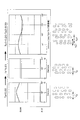
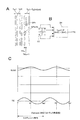
まず図10は、従前のブルーレイディスクシステムで見られる信号波形を示している。ブルーレイディスクシステムの場合、波長405nmのレーザ(いわゆる青色レーザ)とNAが0.85の対物レンズの組み合わせという条件下で記録再生を行うものとされ、トラックピッチは0.32μmである。
また記録面にはスパイラル状のグルーブが形成され、グルーブが記録トラックとされる。
Here, the reason for forming the information recording track as shown in FIGS.
First, FIG. 10 shows a signal waveform seen in a conventional Blu-ray disc system. In the case of a Blu-ray Disc system, recording / reproduction is performed under the condition of a combination of a laser having a wavelength of 405 nm (so-called blue laser) and an objective lens having an NA of 0.85, and the track pitch is 0.32 μm.
A spiral groove is formed on the recording surface, and the groove serves as a recording track.
図10Aは、いわゆるトラバース状態(レーザスポットが半径方向にトラックを横切っている状態)で観測されるRF信号とプッシュプル信号P/P(トラック線方向に沿って2分割したフォトディテクタの差分であるラジアルプッシュプル信号)を示している。
また図10Bは、SUM信号として、RF信号の低域成分信号と、プッシュプル信号P/Pの拡大図を示している。横軸はデトラックとし、0°〜360°の範囲で示している。360°がトラックピッチ(=周期)に相当する。
FIG. 10A shows the difference between the RF signal observed in the so-called traverse state (the laser spot crossing the track in the radial direction) and the push-pull signal P / P (the difference between the photodetectors divided in two along the track line direction). Push-pull signal).
FIG. 10B shows an enlarged view of the low frequency component signal of the RF signal and the push-pull signal P / P as the SUM signal. The horizontal axis is detrack and is shown in the range of 0 ° to 360 °. 360 ° corresponds to the track pitch (= period).
RF信号、SUM信号、プッシュプル信号P/Pとも、トラバース時に横切るグルーブ/ランドに応じた信号変調が観測される。プッシュプル信号P/Pによればレーザスポットのラジアル方向の位置情報(トラッキングエラー信号)が検出できることも理解される。 In the RF signal, the SUM signal, and the push-pull signal P / P, signal modulation corresponding to the groove / land that traverses during traverse is observed. It is understood that the position information (tracking error signal) in the radial direction of the laser spot can be detected by the push-pull signal P / P.
ここで、高密度記録のために狭トラックピッチ化を進めることを考える。
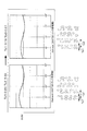
図11は、トラックピッチTpを0.32μmから、0.27μm、0.23μmとした場合に観測されるSUM信号とプッシュプル信号P/Pを示している。
なお横軸のデトラックとして「G」はグルーブ中央位置、「L」はランド中央位置である。
この図11からわかるように、トラックピッチを狭くしていくと、SUM信号、プッシュプル信号P/Pとも変調成分が減少していき、0.23μmとした場合は、変調成分は観測されない。
トラックピッチ0.23μmとは、波長405nmのレーザとNAが0.85の光学系の場合に、ほぼ光学的カットオフより短いピッチとなる。
Here, it is considered to reduce the track pitch for high density recording.
FIG. 11 shows the SUM signal and the push-pull signal P / P that are observed when the track pitch Tp is changed from 0.32 μm to 0.27 μm and 0.23 μm.
As detrack on the horizontal axis, “G” is the groove center position, and “L” is the land center position.
As can be seen from FIG. 11, as the track pitch is reduced, the modulation components of both the SUM signal and the push-pull signal P / P decrease. When the track pitch is 0.23 μm, no modulation component is observed.
The track pitch of 0.23 μm is shorter than the optical cutoff in the case of a laser having a wavelength of 405 nm and an optical system having an NA of 0.85.
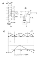
光学的カットオフについて図12で説明する。
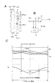
図12にはレーザ光の0次光と回折光(+1次光、−1次光)を示している。回折光のシフト量を図中の矢印SFとして示す。
円の半径を「1」とした場合の回折光のシフト量は、
回折光のシフト量=λ/(NA・p)=(λ/NA)/p
で表される。
但しλは波長、pは周期構造の周期である。周期構造とは、例えばランド/グルーブ等の構造の周期である。
The optical cutoff will be described with reference to FIG.
FIG. 12 shows 0th-order light and diffracted light (+ 1st-order light and −1st-order light) of laser light. The shift amount of the diffracted light is shown as an arrow SF in the figure.
The shift amount of diffracted light when the radius of the circle is “1” is
Diffraction light shift amount = λ / (NA · p) = (λ / NA) / p
It is represented by
Where λ is the wavelength and p is the period of the periodic structure. The periodic structure is a period of a structure such as a land / groove.
フォトディテクタに入射するレーザ光(反射光)については、0次光と、±1次光の重なり部分が変調成分となる。
つまり斜線部として示す重なり部分の面積が大きいほど、フォトディテクタでの検出上で明暗の差が大きくなり、大きな信号変調が得られる。
For the laser light (reflected light) incident on the photodetector, the overlapping portion of the 0th order light and the ± 1st order light becomes a modulation component.
That is, the larger the area of the overlapping portion shown as the hatched portion, the greater the difference in brightness on detection with the photodetector, and the greater the signal modulation.
半径「1」の円とした場合、回折光のシフト量が「2」となると、重なり部分がなくなり、変調成分が得られなくなる。
つまり、(λ/NA)/p=2となると、変調信号が得られない。
ブルーレイディスクシステムの波長λやNAの場合、シフト量が「2」となる周期構造の周期pは0.24μmとなる。
従って、周期構造の周期pに相当するトラックピッチとしては、0.24μmが光学的カットオフ相当のピッチとなる。
In the case of a circle having a radius of “1”, when the shift amount of the diffracted light is “2”, there is no overlapping portion and a modulation component cannot be obtained.
That is, when (λ / NA) / p = 2, a modulation signal cannot be obtained.
In the case of the wavelength λ or NA of the Blu-ray Disc system, the period p of the periodic structure with the shift amount “2” is 0.24 μm.
Accordingly, the track pitch corresponding to the period p of the periodic structure is 0.24 μm, which corresponds to the optical cutoff.
整理すると次のようになる。
・周期p≦λ/(2NA)のときは、変調信号が得られない。
・周期p>λ/(2NA)のときは、変調信号が得られる。
The following is a summary.
When the period p ≦ λ / (2NA), a modulation signal cannot be obtained.
When the period p> λ / (2NA), a modulation signal is obtained.
このことから、狭トラックピッチ化による高密度記録を考えた場合、光学的カットオフ相当を越える狭トラックピッチ化はできないこととなる。
従ってブルーレイディスクシステムと同様の波長、NAで考えたら、トラックピッチは0.25μmが限界で、実際には0.25μmでは殆ど変調成分が得られないため、0.27μm程度以上が現実的なトラックピッチとなる。
For this reason, when considering high density recording by narrowing the track pitch, it is impossible to narrow the track pitch beyond the optical cutoff.
Therefore, when considering the same wavelength and NA as the Blu-ray Disc system, the track pitch is limited to 0.25 μm, and in reality, almost no modulation component can be obtained at 0.25 μm. It becomes pitch.
さらに、ブルーレイディスクシステムの場合、グルーブ/ランド構造を有するが、本実施の形態の光ディスク90は、レイヤーLにグルーブ/ランド構造を形成しない。
各レイヤーLにグルーブ/ランド構造を形成しないのは、多層化に有利であるからである。
Furthermore, in the case of a Blu-ray disc system, it has a groove / land structure, but the
The reason why the groove / land structure is not formed in each layer L is that it is advantageous for multilayering.
このような状況において、狭トラックピッチ化による大幅な高密度記録を検討した。
グルーブ/ランド構造を形成しない場合、マーク列またはエンボスピット列としてのトラック自体が、ラジアル方向での信号変調に影響を与える周期構造となる。
すると、上述した光学的カットオフ相当以下のトラックピッチTp1のみで情報記録トラックを形成すると、変調成分が得られず、トラッキングサーボをかけられないこととなる。
Under such circumstances, a large density recording by narrowing the track pitch was examined.
When the groove / land structure is not formed, the track itself as the mark row or the embossed pit row has a periodic structure that affects the signal modulation in the radial direction.
Then, if an information recording track is formed only with the track pitch Tp1 less than or equal to the optical cut-off described above, a modulation component cannot be obtained and tracking servo cannot be applied.
ところが、反射光情報の信号として変調成分を得るためには、周期p≦λ/(2NA)となる光学的カットオフ以下相当のトラックピッチTp1を含んでいたとしても、周期p>λ/(2NA)となるようにトラック群を構成すればよいことを見いだした。つまりトラック群による周期構造として、そのトラック群が光学的カットオフ相当より大きいトラック群ピッチTpGで形成されているようにすればよい。
即ち図2,図3,図4で例示したような構造の情報記録トラックを形成することで、光学的カットオフ相当以下のトラックピッチTp1を含んでいても、反射光情報として変調成分を得ることができる。
However, in order to obtain a modulation component as a signal of reflected light information, even if a track pitch Tp1 corresponding to an optical cutoff equal to or less than the optical cutoff with the period p ≦ λ / (2NA) is included, the period p> λ / (2NA I found that the track group should be configured so that That is, as a periodic structure of track groups, the track groups may be formed with a track group pitch TpG that is larger than the optical cutoff.
That is, by forming an information recording track having the structure illustrated in FIGS. 2, 3, and 4, a modulation component is obtained as reflected light information even if the track pitch Tp1 is equal to or less than the optical cutoff. Can do.
図13に、波長λ=405nm、NA=0.85において、レイヤーLにグルーブ/ランド構造を設けない場合において、各種トラックピッチ構造でのSUM信号とプッシュプル信号P/Pを示す。
まず、先にも述べたように通常のブルーレイディスクシステムと同様に、トラックピッチTp=0.32μmとすると、SUM信号の変調は観測される。
そしてそのままトラックピッチを詰めていき、光学的カットオフ相当以下のトラックピッチTp=0.23μmとすると、変調成分は観測されなくなる。
ここで、図2のようなトラックピッチTp1、Tp2を有するトラック構造とする。ここではTp1=0.20μm、Tp2=0.30μmとしている。すると、SUM信号として変調成分が観測される。つまりデトラック量に応じた変調成分が得られることとなる。この場合、トラック群ピッチTpG=0.50μmである。
FIG. 13 shows SUM signals and push-pull signals P / P in various track pitch structures when the layer L does not have a groove / land structure at a wavelength λ = 405 nm and NA = 0.85.
First, as described above, the modulation of the SUM signal is observed when the track pitch Tp = 0.32 μm as in the normal Blu-ray disc system.
If the track pitch is reduced as it is and the track pitch Tp equal to or less than the optical cutoff is Tp = 0.23 μm, the modulation component is not observed.
Here, a track structure having track pitches Tp1 and Tp2 as shown in FIG. Here, Tp1 = 0.20 μm and Tp2 = 0.30 μm. Then, a modulation component is observed as a SUM signal. That is, a modulation component corresponding to the detrack amount is obtained. In this case, the track group pitch TpG = 0.50 μm.
なお、このTp1=0.20μm、Tp2=0.30μmの場合の信号波形の図においては、横軸のデトラックにおける360°とは、トラック群周期(トラック群ピッチTpGに相当)のこととなる。Tp=0.32μmの場合、及びTp=0.23μmの場合(さらに図10,図11の場合)では、横軸のデトラックにおける360°がトラック周期であることと異なっている点に注意されたい。
つまり、Tp1=0.20μm、Tp2=0.30μmの場合は、SUM信号は、トラック群の周期の単位で1周期の変調成分が得られていることを示している。
以降の図面においても、トラック群構造を有する場合のデトラックの表記は、360°とは、トラック群周期のことである。
また、レイヤーLがグルーブ/ランド構造が無いミラー面構造である場合、記録したマークに位相差がなければプッシュプル信号P/Pは得られない。
In the signal waveform diagram in the case of Tp1 = 0.20 μm and Tp2 = 0.30 μm, 360 ° in the detrack on the horizontal axis is the track group period (corresponding to the track group pitch TpG). . When Tp = 0.32 μm and when Tp = 0.23 μm (further, in FIGS. 10 and 11), it is noted that 360 ° in the detrack on the horizontal axis is different from the track period. I want.
That is, when Tp1 = 0.20 μm and Tp2 = 0.30 μm, the SUM signal indicates that one period of the modulation component is obtained in the unit of the period of the track group.
Also in the subsequent drawings, the notation of detrack in the case of having a track group structure is 360 ° means a track group period.
If the layer L has a mirror surface structure without a groove / land structure, the push-pull signal P / P cannot be obtained unless the recorded mark has a phase difference.
Tp1=0.20μm、Tp2=0.30μmの場合で、十分なSUM信号の変調が得られたことから、さらに狭トラックピッチ化を検討したのが図14である。
図14では、Tp1=0.19μm、Tp2=0.27μmの場合を、追加して示しているが、この場合も、十分なSUM信号の変調が得られている。この場合、トラック群ピッチTpG=0.46μmであり、これは、トラックピッチの平均値が0.23μmすなわち、図13で変調成分が観測されなくなるトラックピッチに等しくなる状態でも、充分な変調が得られることを意味している。
In the case of Tp1 = 0.20 μm and Tp2 = 0.30 μm, sufficient SUM signal modulation was obtained. FIG. 14 shows the further narrowing of the track pitch.
In FIG. 14, the case of Tp1 = 0.19 μm and Tp2 = 0.27 μm is additionally shown, but also in this case, sufficient SUM signal modulation is obtained. In this case, the track group pitch TpG = 0.46 μm, which means that the average value of the track pitch is 0.23 μm, that is, sufficient modulation is obtained even when the track pitch is equal to the track pitch at which no modulation component is observed in FIG. Is meant to be.
以上のように、実施の形態の情報記録トラックの構造とすることで、光学的カットオフ相当以下のトラックピッチTp1を有していたとしても、光学的カットオフに達しない周期構造、つまりトラック群ピッチTpGのトラック群を有することで、ラジアル方向(トラッキング制御方向)に対応する信号の変調成分が得られることが確認された。
As described above, by adopting the structure of the information recording track according to the embodiment, even if the track pitch Tp1 is equal to or less than the optical cutoff, the periodic structure that does not reach the optical cutoff, that is, the track group It was confirmed that the modulation component of the signal corresponding to the radial direction (tracking control direction) can be obtained by having the track group with the pitch TpG.
<5.トラッキング手法>
このようにSUM信号として変調成分が得られることから、本実施の形態の光ディスク90については、以下の図15〜図21で例示するトラッキング手法が可能となる。
<5. Tracking method>
Since the modulation component is obtained as the SUM signal in this way, the tracking method exemplified in FIGS. 15 to 21 below can be used for the
図15は、図6A或いは図8Bの記録動作や図6Cの再生動作に適用できるトラッキングエラー信号の演算手法を示している。
図15Aは、2重スパイラル構造の情報記録トラックを示している。
再生用レーザスポットSPp1、SPp2はトラッキングエラー信号を検出するためのサーボ用のレーザ光とする。そしてこの再生用レーザスポットSPp1、SPp2が、2重スパイラルのトラックTKx、TKx+1のトラック群に対してトレースするようにトラッキング制御を行う。
例えばトラックTKx、TKx+1の中央を、デトラック量270°の位置とする。(360°はトラック群の周期:以下図16〜図22においても同様)
FIG. 15 shows a tracking error signal calculation method applicable to the recording operation of FIG. 6A or FIG. 8B and the reproduction operation of FIG. 6C.
FIG. 15A shows an information recording track having a double spiral structure.
The reproduction laser spots SPp1 and SPp2 are servo laser beams for detecting a tracking error signal. Then, tracking control is performed so that the reproduction laser spots SPp1 and SPp2 trace with respect to the double spiral tracks TKx and TKx + 1.
For example, the center of the tracks TKx and TKx + 1 is set to a position with a detrack amount of 270 °. (360 ° is the period of the track group: the same applies to FIGS. 16 to 22 below)
再生用レーザスポットSPp1,SPp2の各反射光量信号をS1,S2とする。この場合、図15Bに示すように、差動演算回路31により反射光量信号S2−S1の演算を行うことで、トラッキングエラー信号TEを生成できる。
反射光量信号S1,S2としては、図15Cに示すようにラジアルコントラスト信号としての変調成分が得られる。
例えば再生用レーザスポットSPp1,SPp2が図15Aで右にずれると、反射光量信号S1は暗くなり(信号レベルが低下し)、反射光量信号S2は明るくなる(信号レベルが増加する)。
なお、ここではTp1=0.19μm、Tp2=0.27μmの場合(TpG=0.46)で示している。またこの場合のSUM信号は、再生用レーザスポットSPp1、SPp2のディスク半径方向での中間位置に仮想的なスポットを考えた場合の信号である。
そしてラジアルコントラスト成分の差分であるS2−S1として、トラック群の単位でのデトラック量に応じたトラッキングエラー信号TEが得られる。
このトラッキングエラー信号TEに基づいて270°位置にサーボ制御することで、図15Aのような再生用レーザスポットSPp1,SPp2によるトラッキング制御が可能となる。これによって図6A或いは図8Bの記録動作や図6Cの再生動作が実行できる。
The reflected light amount signals of the reproduction laser spots SPp1 and SPp2 are denoted by S1 and S2. In this case, as shown in FIG. 15B, the tracking error signal TE can be generated by calculating the reflected light amount signal S <b> 2-S <b> 1 by the
As the reflected light amount signals S1 and S2, modulation components as radial contrast signals are obtained as shown in FIG. 15C.
For example, when the reproduction laser spots SPp1 and SPp2 are shifted to the right in FIG. 15A, the reflected light amount signal S1 becomes dark (the signal level decreases) and the reflected light amount signal S2 becomes bright (the signal level increases).
In this example, Tp1 = 0.19 μm and Tp2 = 0.27 μm are shown (TpG = 0.46). Further, the SUM signal in this case is a signal when a virtual spot is considered at an intermediate position in the disk radial direction of the reproduction laser spots SPp1 and SPp2.
A tracking error signal TE corresponding to the detrack amount in units of track groups is obtained as S2-S1, which is the difference between the radial contrast components.
By performing servo control to the 270 ° position based on the tracking error signal TE, tracking control by the reproduction laser spots SPp1 and SPp2 as shown in FIG. 15A becomes possible. Thereby, the recording operation of FIG. 6A or FIG. 8B and the reproducing operation of FIG. 6C can be executed.
ところで図15Bでは、反射光量信号S1,S2をクロストークキャンセル回路6に入力し、クロストークキャンセル回路6からのバランス制御信号TK−BLで差動演算回路31の動作を調整している。
これは、単純に反射光量信号S1,S2の差動をとるだけでは、各トラックの記録状態によってバランスがずれることがあるためである。クロストークキャンセル回路6では、隣接トラックのクロストーク成分を検出するため、これによってトラックTKx、TKx+1の光量バランスのずれを補正することが可能である。そこでクロストークキャンセル回路6は、隣接トラックのクロストーク成分が互いにバランスするように、バランス制御信号TK−BLを出力する。
差動演算回路31では、バランス制御信号TK−BLに応じて、反射光量信号S1,S2のそれぞれに、各トラックの記録状態に対応した補正係数をかけるようなバランス調整演算を行った上で、S2−S1の演算を行ったり、その演算結果に適宜オフセットバイアスを加えたりすることによって、記録状態の影響を受けにくいトラッキングエラー信号TEを生成するようにする。
In FIG. 15B, the reflected light amount signals S1 and S2 are input to the crosstalk cancel circuit 6, and the operation of the differential
This is because the balance may be shifted depending on the recording state of each track by simply taking the differential between the reflected light amount signals S1 and S2. Since the crosstalk cancel circuit 6 detects the crosstalk component of the adjacent track, it is possible to correct the deviation of the light quantity balance between the tracks TKx and TKx + 1. Therefore, the crosstalk cancellation circuit 6 outputs a balance control signal TK-BL so that the crosstalk components of adjacent tracks are balanced with each other.
The
なお、図15では図示を省略したが、クロストークキャンセル回路6でクロストークキャンセル処理を施された反射光量信号S1,S2は、図5に示したデータ検出処理部5に供給される。
即ち図6Cの再生を行う場合、反射光量信号S1,S2がトラックTKx、TKx+1についてのRF信号として、データ再生に用いられる。
Although not shown in FIG. 15, the reflected light amount signals S1 and S2 subjected to the crosstalk cancellation processing by the crosstalk cancellation circuit 6 are supplied to the data
That is, when the reproduction of FIG. 6C is performed, the reflected light amount signals S1 and S2 are used for data reproduction as RF signals for the tracks TKx and TKx + 1.
次に図16は、図6Bの記録動作に適用できるトラッキングエラー信号の演算手法を示している。
図16Aに示すように、再生用レーザスポットSPp1、SPp2はトラッキングエラー信号を検出するためのサーボ用のレーザ光とし、この再生用レーザスポットSPp1、SPp2が、2重スパイラルの一方のトラックTKxを挟み込みながらトレースするようにトラッキング制御を行う。
この状態で、隣接トラッキングサーボを行い、記録用レーザスポットSPrにより、隣接するトラックTKx+1を記録していく。
この場合も、トラッキングエラー信号TEは、図16Bで示すように、差動演算回路31での反射光量信号のS2−S1の演算で得ることができる。またこの場合も、クロストークキャンセル回路6からのバランス制御信号TK−BLで反射光量信号S1,S2の調整を行っても良い。
Next, FIG. 16 shows a tracking error signal calculation method applicable to the recording operation of FIG. 6B.
As shown in FIG. 16A, the reproduction laser spots SPp1 and SPp2 are servo laser beams for detecting a tracking error signal, and the reproduction laser spots SPp1 and SPp2 sandwich one track TKx of the double spiral. Tracking control is performed so that tracing is performed.
In this state, the adjacent tracking servo is performed, and the adjacent track TKx + 1 is recorded by the recording laser spot SPr.
Also in this case, the tracking error signal TE can be obtained by calculating S2-S1 of the reflected light amount signal in the
なお、記録時にはトラックピッチが広いため、再生用レーザスポットSPp1、SPp2からのRF出力は、その大半がトラックTKxからのものとなり、再生用レーザスポットSPp1、SPp2からのRF出力及び出力信号の比較結果を用いて、トラックTKxの信号再生、及びバランス制御信号TK−BLを得ることができる。 Since the track pitch is wide at the time of recording, most of the RF outputs from the reproduction laser spots SPp1 and SPp2 are from the track TKx, and the comparison result of the RF output and output signal from the reproduction laser spots SPp1 and SPp2 Can be used to obtain the signal reproduction of the track TKx and the balance control signal TK-BL.
図16Cに各種信号波形を示す。なお、トラック軌道TKaのトラックが記録されており、その後にトラック軌道TKbのトラックを記録していく場合で示しているため、記録前のトラックピッチはTp1+Tp2=0.46μmとなる。
反射光量信号S1,S2、及びSUM信号として、図示のようにラジアルコントラスト変調成分が得られる。そしてS2−S1として、デトラック量に応じたトラッキングエラー信号TEが得られる。
この場合、トラッキングエラー信号TEに基づいて0°位置にサーボ制御することで、図16Aのような再生用レーザスポットSPp1,SPp2によるトラッキング制御が可能となる。これによって図6Bの記録動作が実行できる。
FIG. 16C shows various signal waveforms. Since the track of track orbit TKa is recorded and the track of track orbit TKb is recorded thereafter, the track pitch before recording is Tp1 + Tp2 = 0.46 μm.
As shown in the figure, radial contrast modulation components are obtained as the reflected light quantity signals S1, S2 and the SUM signal. As S2-S1, a tracking error signal TE corresponding to the detrack amount is obtained.
In this case, by performing servo control to the 0 ° position based on the tracking error signal TE, tracking control by the reproduction laser spots SPp1 and SPp2 as shown in FIG. 16A becomes possible. Thereby, the recording operation of FIG. 6B can be executed.
続いて図17は、図7Aの記録動作や、図7C又は図7Dの再生動作に適用できるトラッキングエラー信号の演算手法を示している。
図17Aに示すように、情報記録トラックの接線方向に対して略45°の角度をなす非点収差を与えたサーボ用レーザスポットSPp45を光ディスク90のレイヤーLに照射する。そしてサーボ用レーザスポットSPp45が、トラックTKx、TKx+1のトラック群に対してトレースするようにトラッキング制御を行う。
FIG. 17 shows a tracking error signal calculation method applicable to the recording operation of FIG. 7A and the reproducing operation of FIG. 7C or 7D.
As shown in FIG. 17A, a servo laser spot SPp45 with astigmatism that forms an angle of about 45 ° with respect to the tangential direction of the information recording track is irradiated onto the layer L of the
この場合、光ピックアップ1では、図17Bに示す4分割フォトディテクタ33で、サーボ用レーザスポットSPp45の反射光を受光する。受光面A,B,C,Dで得られる各信号は演算回路34に供給される。
演算回路34では、受光面A+Dの信号から、受光面B+Cの信号を減算して、これをトラッキングエラー信号TEとして出力する。即ちトラック線方向に対して垂直方向に分割した各フォトディテクタの差分信号であるタンジェンシャルプッシュプル信号がトラッキングエラー信号TEとなる。
In this case, in the
The
図17Cに信号波形を示す。ここではTp1=0.20μm、Tp2=0.30μm、TpG=0.50μmの場合で示している。
また非点収差量はZ6=0.275の場合である。(Z6は、フリンジ−ゼルニケの収差多項式におけるZ6)
図示のようにタンジェンシャルプッシュプル信号によるトラッキングエラー信号TEとして、デトラック量に応じた信号が得られる。
このトラッキングエラー信号TEに基づいて270°位置にサーボ制御することで、図17Aのようにサーボ用レーザスポットSPp45をトラック群にトレースさせるトラッキング制御が可能となる。これによって図7Aの記録動作や図7Cの再生動作が実行できる。
FIG. 17C shows a signal waveform. Here, the case where Tp1 = 0.20 μm, Tp2 = 0.30 μm, and TpG = 0.50 μm is shown.
The amount of astigmatism is when Z6 = 0.275. (Z6 is Z6 in Fringe-Zernike aberration polynomial)
As shown in the figure, a signal corresponding to the detrack amount is obtained as the tracking error signal TE by the tangential push-pull signal.
By performing servo control to the 270 ° position based on the tracking error signal TE, tracking control for tracing the servo laser spot SPp45 to the track group as shown in FIG. 17A becomes possible. Thereby, the recording operation of FIG. 7A and the reproduction operation of FIG. 7C can be executed.
次に図18は、図7Bの記録動作に適用できるトラッキングエラー信号の演算手法を示している。
図18Aに示すように、サーボ用レーザスポットSPp45を光ディスク90のレイヤーLに照射し、2重スパイラルのうちで既に形成されているトラックTKxをトレースさせる。
この状態で、隣接トラッキングサーボを行い、記録用レーザスポットSPrにより、隣接するトラックTKx+1を記録していく。
Next, FIG. 18 shows a tracking error signal calculation method applicable to the recording operation of FIG. 7B.
As shown in FIG. 18A, the servo laser spot SPp45 is applied to the layer L of the
In this state, the adjacent tracking servo is performed, and the adjacent track TKx + 1 is recorded by the recording laser spot SPr.
この場合も図18Bに示すように、演算回路34で(A+D)−(B+C)の演算を行って得られるタンジェンシャルプッシュプル信号がトラッキングエラー信号TEとなる。
図18Cに信号波形を示す。なお、トラック軌道TKaのトラックが記録されており、その後にトラック軌道TKbのトラックを記録していく場合で示しているため、記録前のトラックピッチはTp1+Tp2=0.46μmとなる。また非点収差量はZ6=0.262の場合である。
図示のようにタンジェンシャルプッシュプル信号によるトラッキングエラー信号TEとして、デトラック量に応じた信号が得られる。
このトラッキングエラー信号TEに基づいて0°位置にサーボ制御することで、図18Aのようにサーボ用レーザスポットSPp45をトラックTKxにトレースさせるトラッキング制御が可能となる。これによって図7Bの記録動作が実行できる。
Also in this case, as shown in FIG. 18B, the tangential push-pull signal obtained by calculating (A + D) − (B + C) by the
FIG. 18C shows a signal waveform. Since the track of track orbit TKa is recorded and the track of track orbit TKb is recorded thereafter, the track pitch before recording is Tp1 + Tp2 = 0.46 μm. The amount of astigmatism is when Z6 = 0.262.
As shown in the figure, a signal corresponding to the detrack amount is obtained as the tracking error signal TE by the tangential push-pull signal.
By performing servo control to the 0 ° position based on the tracking error signal TE, tracking control for tracing the servo laser spot SPp45 on the track TKx as shown in FIG. 18A becomes possible. Thereby, the recording operation of FIG. 7B can be executed.
続いて図19は、図8Aの記録動作や図8Cの再生動作に適用できるトラッキングエラー信号の演算手法を示している。
図19Aは、3重スパイラル構造の情報記録トラックを示している。
再生用レーザスポットSPp1、SPp0、SPp2はトラッキングエラー信号を検出するためのサーボ用のレーザ光とする。そしてこの再生用レーザスポットSPp1、SPp0、SPp2が、3重スパイラルのトラックTKx、TKx+1、TKx+2のトラック群に対してトレースするようにトラッキング制御を行う。
トラックTKx、TKx+1、TKx+2の中央を、デトラック=270°の位置とする。
Next, FIG. 19 shows a tracking error signal calculation method applicable to the recording operation of FIG. 8A and the reproducing operation of FIG. 8C.
FIG. 19A shows an information recording track having a triple spiral structure.
The reproduction laser spots SPp1, SPp0, SPp2 are servo laser beams for detecting a tracking error signal. Then, tracking control is performed so that the reproduction laser spots SPp1, SPp0, and SPp2 trace the triple spiral tracks TKx, TKx + 1, and TKx + 2.
The center of the tracks TKx, TKx + 1, and TKx + 2 is set to a position of detrack = 270 °.
再生用レーザスポットSPp1,SPp0、SPp2の各反射光量信号をS1,S0,S2とする。この場合、図19Bに示すように、差動演算回路31により反射光量信号S2−S1の演算を行うことで、トラッキングエラー信号TEを生成できる。
反射光量信号S1,S0,S2としては、図19Cに示すようにラジアルコントラスト信号としての変調成分が得られる。なお、ここではTp1=0.19μm、Tp2=0.26μmの場合で示している。
そしてラジアルコントラスト成分の差分であるS2−S1として、デトラック量に応じたトラッキングエラー信号TEが得られる。
このトラッキングエラー信号TEに基づいて270°位置にサーボ制御することで、図19Aのような再生用レーザスポットSPp1,SPp2によるトラッキング制御が可能となる。これによって図8Aの記録動作や図8Cの再生動作が実行できる。
The reflected light amount signals of the reproduction laser spots SPp1, SPp0, SPp2 are denoted by S1, S0, S2. In this case, as shown in FIG. 19B, the tracking error signal TE can be generated by calculating the reflected light amount signal S2-S1 by the
As the reflected light quantity signals S1, S0, and S2, modulation components as radial contrast signals are obtained as shown in FIG. 19C. Here, the case where Tp1 = 0.19 μm and Tp2 = 0.26 μm is shown.
A tracking error signal TE corresponding to the detrack amount is obtained as S2-S1, which is the difference in radial contrast components.
By performing servo control to the 270 ° position based on the tracking error signal TE, tracking control by the reproduction laser spots SPp1 and SPp2 as shown in FIG. 19A becomes possible. Thereby, the recording operation of FIG. 8A and the reproduction operation of FIG. 8C can be executed.
また図19Bでは、反射光量信号S1,S0,S2をクロストークキャンセル回路6に入力し、クロストークキャンセル回路6からのバランス制御信号TK−BLで差動演算回路31の動作を調整している。
先に図15の場合で述べたように、差動演算回路31が、バランス制御信号TK−BLに応じて、反射光量信号S1,S2のそれぞれに、各トラックの記録状態に対応した補正係数をかけるようなバランス調整演算を行った上で、S2−S1の演算を行ったり、その演算結果に適宜オフセットバイアスを加えたりすることによって、記録状態の影響を受けにくいトラッキングエラー信号TEを生成できる。
In FIG. 19B, the reflected light quantity signals S1, S0, S2 are input to the crosstalk cancel circuit 6, and the operation of the differential
As described above with reference to FIG. 15, the differential
なお、図19では図示を省略したが、クロストークキャンセル回路6でクロストークキャンセル処理を施された反射光量信号S1,S0,S2は、図5に示したデータ検出処理部5に供給される。
即ち図8Cの再生を行う場合、反射光量信号S1,S0,S2がトラックTKx、TKx+1、TKx+2についてのRF信号として、データ再生に用いられる。
Although not shown in FIG. 19, the reflected light amount signals S1, S0, S2 subjected to the crosstalk cancellation processing by the crosstalk cancellation circuit 6 are supplied to the data
That is, when the reproduction of FIG. 8C is performed, the reflected light amount signals S1, S0, and S2 are used for data reproduction as RF signals for the tracks TKx, TKx + 1, and TKx + 2.
次に図20は、例えば図8Bのように、既にトラック軌道TKa、TKbのトラックが形成されている状態で、3つめのトラック軌道TKcを記録する際に、非点収差を与えたサーボ用レーザスポットSPp45を用いてトラッキングを行う例である。
図8Bの記録動作は、先に図15で述べたように2つの再生用レーザスポットSPp1、SPp2を用いてトラッキングサーボ方式を実行すれば良いが、ここでは、1つのサーボ用レーザスポットSPp45を用いる例を示したものである。
Next, FIG. 20 shows a servo laser to which astigmatism is given when recording a third track orbit TKc in a state where tracks of track orbits TKa and TKb are already formed as shown in FIG. 8B, for example. In this example, tracking is performed using a spot SPp45.
In the recording operation of FIG. 8B, the tracking servo method may be executed using the two reproduction laser spots SPp1 and SPp2 as described above with reference to FIG. 15, but here, one servo laser spot SPp45 is used. An example is shown.
図20Aに示すように、サーボ用レーザスポットSPp45が、既に形成されているトラック軌道TKa、TKbのトラックTKx、TKx+1をトレースするようにトラッキング制御を行う。
この場合、図20Bのように演算回路34でタンジェンシャルプッシュプル信号を得ることで、それをトラッキングエラー信号TEとすることができる。
図20Cのようにトラッキングエラー信号TEとして、デトラック量に応じた信号が得られる。
このトラッキングエラー信号TEに基づいて90°位置にサーボ制御することで、図20Aのようにサーボ用レーザスポットSPp45をトラックTKx、TKx+1にトレースさせるトラッキング制御が可能となる。この状態での隣接トラッキングサーボによって記録用レーザスポットSPrで、3つめのトラック軌道TKcのトラックを記録していくことができる。
As shown in FIG. 20A, tracking control is performed so that the servo laser spot SPp45 traces the tracks TKx and TKx + 1 of the already formed track trajectories TKa and TKb.
In this case, by obtaining the tangential push-pull signal by the
As shown in FIG. 20C, a signal corresponding to the detrack amount is obtained as the tracking error signal TE.
By performing servo control at a 90 ° position based on the tracking error signal TE, tracking control for tracing the servo laser spot SPp45 on the tracks TKx and TKx + 1 as shown in FIG. 20A becomes possible. The track of the third track orbit TKc can be recorded by the recording laser spot SPr by the adjacent tracking servo in this state.
図21は、図19で述べたトラッキングサーボ方式と同様のサーボ方式であるが、3重スパイラルの情報記録トラックの内、トラック軌道TKa、TKcのトラックが既に形成され、真ん中のトラック軌道TKbが未記録の状態でのトラッキングサーボ方式を示している。
図21Aのように、真ん中のトラック軌道TKbのトラックが未記録であることから、トラック軌道TKaのトラックとトラック軌道TKcのトラックの間のピッチはTp1+Tp1=0.38となっている。またトラック群の間のトラックピッチTp2=0.26としている。
図21Bのトラッキングエラー信号TEの生成方式gは図19Bと同様である。
FIG. 21 is a servo system similar to the tracking servo system described in FIG. 19, but the track orbits TKa and TKc of the triple spiral information recording track are already formed, and the middle track orbit TKb is not yet formed. The tracking servo system in the recording state is shown.
As shown in FIG. 21A, since the track of the middle track orbit TKb is not recorded, the pitch between the track of track orbit TKa and the track of track orbit TKc is Tp1 + Tp1 = 0.38. The track pitch Tp2 = 0.26 between the track groups is set.
The generation method g of the tracking error signal TE in FIG. 21B is the same as that in FIG. 19B.
図21Cに各信号の波形を示す。この場合、真ん中のスパイラルが存在しないことで、トラッキングエラー信号TEの極性が図19の場合とは逆になるが、例えば270°位置にサーボ制御することで、図21Aのようなトラッキングサーボが可能となる。
このように、3重スパイラルの真ん中のスパイラルのトラックが未記録の状態でも、サーボ制御を行って記録または再生を行うことができる。
FIG. 21C shows the waveform of each signal. In this case, the polarity of the tracking error signal TE is reversed from the case of FIG. 19 because the middle spiral is not present, but tracking servo as shown in FIG. It becomes.
As described above, even if the spiral track in the middle of the triple spiral is unrecorded, the servo control can be performed to perform recording or reproduction.
ところで、トラックピッチTp1だけでなく、トラックピッチTp2も光学的カットオフ相当以下のトラックピッチであってもよいと先に述べた。
上記図15〜図21の例では、トラックピッチTp2は光学的カットオフ相当よりも長い例を示しており、その場合、トラック群ピッチTpGは、必然的に光学的カットオフ相当よりも長くなる。
図22では、トラックピッチTp1、Tp2とも光学的カットオフ相当以下であっても、トラック群ピッチTpGが光学的カットオフ相当よりも長くされていれば、トラッキングエラー信号TEが得られることを示している。
By the way, as described above, not only the track pitch Tp1 but also the track pitch Tp2 may be a track pitch equal to or less than the optical cutoff.
In the examples of FIGS. 15 to 21, the track pitch Tp2 is longer than the optical cutoff, and in this case, the track group pitch TpG is necessarily longer than the optical cutoff.
FIG. 22 shows that the tracking error signal TE can be obtained if the track group pitch TpG is longer than the optical cutoff even if the track pitches Tp1 and Tp2 are less than or equal to the optical cutoff. Yes.
図22A、図22B、図22Cは、図15と同様に、2重スパイラル構造の情報記録トラックに対して、再生用レーザスポットSPp1、SPp2のラジアルコントラスト信号によりトラッキングエラー信号TEを得る場合を示している。
この場合、トラックピッチTp1=0.15μm、Tp2=0.23μmとしており、共に光学的カットオフ相当以下のトラックピッチである。トラック群ピッチTpGは、0.38μmとなる。
反射光量信号S1,S2としては、図22Cに示すようにラジアルコントラスト信号としての変調成分が得られる。
そしてラジアルコントラスト成分の差分であるS2−S1として、デトラック量に応じたトラッキングエラー信号TEが得られる。
このトラッキングエラー信号TEに基づいて270°位置にサーボ制御することで、図22Aのような再生用レーザスポットSPp1,SPp2によるトラッキング制御が可能となる。
22A, 22B, and 22C show the case where the tracking error signal TE is obtained from the radial contrast signals of the reproduction laser spots SPp1 and SPp2 with respect to the information recording track having the double spiral structure, as in FIG. Yes.
In this case, the track pitch Tp1 = 0.15 μm and Tp2 = 0.23 μm, both of which are less than or equal to the optical cutoff. The track group pitch TpG is 0.38 μm.
As the reflected light quantity signals S1 and S2, modulation components as radial contrast signals are obtained as shown in FIG. 22C.
A tracking error signal TE corresponding to the detrack amount is obtained as S2-S1, which is the difference in radial contrast components.
By performing servo control to the 270 ° position based on the tracking error signal TE, tracking control by the reproduction laser spots SPp1 and SPp2 as shown in FIG. 22A becomes possible.
このように、トラックピッチTp1、Tp2が光学的カットオフ相当以下のトラックピッチであっても、トラック群ピッチTpGが光学的カットオフ相当よりも長くされていれば、適正なトラッキングサーボが可能となる。
なお、図22では図15のトラッキング方式に準拠して述べたが、図16〜図21で述べたトラッキング方式の場合でも、トラックピッチTp1、Tp2が光学的カットオフ相当以下のトラックピッチであっても、トラック群ピッチTpGが光学的カットオフ相当よりも長くされていれば、適正なトラッキングサーボが可能となる。
As described above, even if the track pitches Tp1 and Tp2 are equal to or less than the optical cut-off, if the track group pitch TpG is longer than the optical cut-off, proper tracking servo can be performed. .
22 is described based on the tracking method of FIG. 15. However, even in the tracking method described with reference to FIGS. 16 to 21, the track pitches Tp1 and Tp2 are track pitches equal to or less than the optical cutoff. However, if the track group pitch TpG is longer than that corresponding to the optical cutoff, appropriate tracking servo can be performed.
<6.光学系構成例>
以上の実施の形態の記録動作、再生動作を実現するための光ピックアップ1の光学系の構成例を説明する。
<6. Example of optical system configuration>
A configuration example of the optical system of the
図23は、例えば図6、図8のように複数のレーザスポットをトラッキングサーボに用いる場合の例である。
光ピックアップ1内の光学系として、マルチビームLD(Lazer diode)41、コリメータレンズ42、ビームスプリッタ43、対物レンズ44、マルチレンズ45、受光素子部46、二軸機構47が設けられる。
FIG. 23 shows an example in which a plurality of laser spots are used for tracking servo as shown in FIGS.
As an optical system in the
マルチビームLD41から出射されたレーザ光はコリメータレンズ42で平行光とされ、ビームスプリッタ43を通過し、対物レンズ44で集光されて光ディスク90に照射される。
対物レンズ44は、二軸機構47によってフォーカス方向及びトラッキング方向に変位可能に保持されている。図5に示した二軸ドライバ18によって二軸機構47が駆動されることで、トラッキングサーボ及びフォーカスサーボが実行される。
The laser light emitted from the
The
光ディスク90からの反射光は、対物レンズ44を介してビームスプリッタ43で反射され、マルチレンズ45に達する。そしてマルチレンズ45で集光され、受光素子部46に入射される。
The reflected light from the
この構成において、マルチビームLD41としては、図中に例1〜例4としての発光面の構成が考えられ、またこのマルチビームLD41の例に対応して、受光素子部46のフォトディテクタ構成として、例1〜例4が考えられる。
In this configuration, as the
例1は、マルチビームLD41が、再生専用の2ビームの発光面を有する構成とされ、また受光素子部46は2つの4分割フォトディテクタPD1,PD2を有する構成とされる。これは再生装置として、例えば図6C及び図15で説明した再生動作を行うことができるようにする場合の構成例である。
2つの再生用レーザスポットSPp1、SPp2を照射するとともに、これらの反射光をフォトディテクタPD1,PD2で検出する。各フォトディテクタPD1,PD2の4分割受光面の和信号が図15でいう反射光量信号S1,S2となる。
また4分割の受光面の各信号の演算により、フォーカスエラー信号等、他の必要な信号が生成される。
In Example 1, the
Two reproducing laser spots SPp1 and SPp2 are irradiated, and the reflected light is detected by the photodetectors PD1 and PD2. The sum signal of the four-divided light receiving surfaces of the photodetectors PD1 and PD2 becomes reflected light amount signals S1 and S2 in FIG.
Further, other necessary signals such as a focus error signal are generated by calculating each signal of the four-divided light receiving surface.
例2は、マルチビームLD41が、再生専用の3ビームの発光面を有する構成とされ、また受光素子部46は2つのフォトディテクタPD3、PD5と、4分割フォトディテクタPD4を有する構成とされる。
これは再生装置として、例えば図8C及び図19で説明した再生動作を行うことができるようにする場合の構成例である。
3つの再生用レーザスポットSPp1、SPp0、SPp2を照射するとともに、これらの反射光をフォトディテクタPD3,PD4,PD5で検出する。フォトディテクタPD3,PD5から図19でいう反射光量信号S1,S2が得られる。またフォトディテクタPD4の4分割受光面の和信号が反射光量信号S0となる。
またフォトディテクタPD4の4分割の受光面の各信号の演算により、フォーカスエラー信号等、他の必要な信号が生成される。
In Example 2, the
This is a configuration example in the case where the reproduction apparatus can perform the reproduction operation described with reference to FIGS. 8C and 19, for example.
The three reproduction laser spots SPp1, SPp0, and SPp2 are irradiated, and these reflected lights are detected by the photodetectors PD3, PD4, and PD5. The reflected light amount signals S1 and S2 shown in FIG. 19 are obtained from the photodetectors PD3 and PD5. Further, the sum signal of the four-divided light receiving surface of the photodetector PD4 becomes the reflected light amount signal S0.
Further, other necessary signals such as a focus error signal are generated by calculating each signal of the four-divided light receiving surface of the photodetector PD4.
例3は、図6(a)の記録動作を行う場合の構成で、マルチビームLD41が、再生用2ビームの発光面と記録用2ビームの発光面を有する構成とされる。これに対応して受光素子部46は再生用レーザスポットSPp1、SPp2用に2つのフォトディテクタPD6、PD7が設けられ、記録用レーザスポットSPr1、SPr2用に2つのフォトディテクタPD8、PD9が設けられる。
Example 3 is a configuration in the case where the recording operation of FIG. 6A is performed, in which the
例4は、図8(a)の記録動作を行う場合の構成で、マルチビームLD41が、再生用3ビームの発光面と記録用3ビームの発光面を有する構成とされる。これに対応して受光素子部46は再生用レーザスポットSPp1、SPp2、SPp3用に3つのフォトディテクタPD10、PD11、PD12が設けられ、記録用レーザスポットSPr1、SPr2、SPr3用に3つのフォトディテクタPD13、PD14、PD15が設けられる。
Example 4 is a configuration in the case where the recording operation of FIG. 8A is performed, in which the
図24は上記の例2、即ち再生専用3ビーム発光面と、これに対応する受光素子部46(フォトディテクタPD3、PD4、PD5)を有する構成を例に挙げて、光ディスク90に3つのレーザスポットを形成するマルチビーム光束を示したものである。
図示のように、マルチビームLD41からの3つのレーザは、コリメータレンズ42、ビームスプリッタ43、対物レンズ44による光学系を経て、ディスク90上の情報記録トラックに対し、3つのスポットを形成する。これが図8C及び図19で説明した再生用レーザスポットSPp1、SPp0、SPp2となる。
またこれら3つのレーザスポットに係る反射光は、対物レンズ44、ビームスプリッタ43、マルチレンズ45の光学系を経て、受光素子部46のフォトディテクタPD3、PD4、PD5に入射されることとなる。
ここでは例2の場合で述べたが、他の例1、例3,例4の場合も、それぞれ同様に考えれば良い。
FIG. 24 shows, as an example, a configuration having the above-described Example 2, that is, a read-only three-beam light emitting surface and a light receiving element portion 46 (photodetectors PD3, PD4, and PD5) corresponding to the three laser spots on the
As shown in the figure, the three lasers from the
Reflected light related to these three laser spots is incident on the photodetectors PD3, PD4, and PD5 of the light
Although the case of Example 2 has been described here, the same applies to the cases of Example 1, Example 3, and Example 4.
図25は、同じく複数のレーザスポットをトラッキングサーボに用いる場合の例であるが、マルチビームLD41を用いない場合の再生用光学系の例を示している。
光ピックアップ1内の光学系として、LD51、コリメータレンズ42、ビームスプリッタ43、グレーティング52、QWP(1/4波長板)53、対物レンズ44、マルチレンズ45、受光素子部46、二軸機構47が設けられる。
FIG. 25 shows an example of a reproducing optical system when a plurality of laser spots are used for tracking servo, but the
As an optical system in the
マルチビームLD41から出射されたレーザ光はコリメータレンズ42で平行光とされ、ビームスプリッタ43を通過し、グレーティング52に達する。
グレーティング52は往路のみ回折する偏光グレーティングとしたり、回折オン/オフ可能な液晶グレーティングとすることができる。
グレーティング52によって得られる0次光と±1次光により、再生用の3ビーム光学系を形成することができる。これにより、図6Cの再生用レーザスポットSPp1、SPp2や、或いは図8Cの再生用レーザスポットSPp1、SPp2、SPp3を得ることができる。
0次光と±1次光はQWP53を経て対物レンズ44で集光されて光ディスク90に照射される。
光ディスク90からの反射光は、対物レンズ44を介してQWP53、グレーティング52を透過し、ビームスプリッタ43で反射され、マルチレンズ45に達する。そしてマルチレンズ45で集光され、受光素子部46に入射される。
受光素子部46では、0次光と±1次光による再生用レーザスポットSPp1、SPp2、SPp3に対応するフォトディテクタが構成されていればよい。
The laser light emitted from the
The grating 52 can be a polarization grating that diffracts only in the forward path, or a liquid crystal grating that can be diffracted on / off.
A three-beam optical system for reproduction can be formed by zero-order light and ± first-order light obtained by the grating 52. Thus, the reproduction laser spots SPp1, SPp2 in FIG. 6C or the reproduction laser spots SPp1, SPp2, SPp3 in FIG. 8C can be obtained.
The zero-order light and the ± first-order light are condensed by the
Reflected light from the
In the light receiving
なお、この図25では1ビームのLD51を有する再生用光学系を示しているが、2ビームLD、3ビームLD等を用いて、記録及び再生可能な光学系を形成することも可能である。
25 shows a reproducing optical system having a one-
図26は、図1Bのような多層の光ディスク90に対応する光学系の例を示している。
基本的な構成は図25の例と同様であるが、球面収差補正用のエキスパンダレンズ54を設けている。エキスパンダレンズ54は固定レンズ54aと可動レンズ54bから成る。可動レンズ54bは矢印V方向、即ち光軸方向に変位可能とされる。
目的とするレイヤーLに応じてエキスパンダレンズ54が駆動され、球面収差補正が行われる構成となる。
FIG. 26 shows an example of an optical system corresponding to the multilayer
The basic configuration is the same as in the example of FIG. 25, but an
The
なお、グレーティング52は、エキスパンダレンズ54とQWP53の間に設けてもよいが、これに代えて、破線のグレーティング52Aとして示すようにコリメータレンズ42とビームスプリッタ43の間に設けるようにしてもよい。
グレーティング52を採用する場合は、偏光依存性が必要であるが、グレーティング52Aを採用する場合は、偏光依存性は不要である。
The grating 52 may be provided between the
When the grating 52 is employed, the polarization dependency is necessary, but when the grating 52A is employed, the polarization dependency is not necessary.
図27は、図26の構成において、光ディスク90に3つのレーザスポットを形成する場合のマルチビーム光束を示したものである。ここではグレーティング52Aを用いた例としている。
LD51から出力されたレーザ光は、グレーティング52Aで0次光、±1次光とされ、3スポットを形成するマルチビームが形成される。これによってディスク90のレイヤーLに照射される3つのレーザスポットとして、図8Cで述べた再生用レーザスポットSPp1、SPp2、SPp3を得ることができる。
これらのレーザスポットに係る反射光は、図示する光束で受光素子部46に入射される。従って受光素子部46では、例えば図23で例2として示したようなフォトディテクタ構成により、反射光を検出するように構成されていればよい。
FIG. 27 shows a multi-beam light beam in the case where three laser spots are formed on the
The laser light output from the
The reflected light related to these laser spots is incident on the light receiving
なお、図26の構成においてLD51や受光素子部46については、図23,図25のような構成例が考えられる。
また、図23,図25,図26の各例において再生用レーザダイオードと、記録用レーザダイオードを独立して設けることも考えられる。
In the configuration of FIG. 26, the
It is also conceivable that the reproducing laser diode and the recording laser diode are provided independently in each of the examples shown in FIGS.
図28は、図1Cのようにリファレンス面RLが設けられた光ディスク90に対応する光学系構成例である。
LD51、コリメータレンズ42、グレーティング52A、ビームスプリッタ43、対物レンズ44、エキスパンダレンズ54、マルチレンズ45、受光素子部46は、図26と同様である。
この場合、異なる波長のレーザ光をリファレンス面RLに集光させる光学系を設ける。
即ちLD65、コリメータレンズ66、ビームスプリッタ67、エキスパンダレンズ60、ダイクロイックプリズム61、2波長QWP及び波長選択開口制限素子62を追加している。
FIG. 28 shows an example of an optical system configuration corresponding to the
The
In this case, an optical system for condensing laser beams having different wavelengths on the reference surface RL is provided.
That is, an
LD65は、LD51とは波長の異なるレーザ光を出力する。例えばLD51を波長405nmの青色レーザとし、LD65は例えば波長650nmの赤色レーザなどとする。
LD65から出射されたレーザ光は、コリメータレンズ66で平行光とされ、ビームスプリッタ67を介して、エキスパンダレンズ60に導かれる。
エキスパンダレンズ60は、固定レンズ60aと可動レンズ60bからなり、赤色レーザ光のレーザスポットをリファレンス面RLに合焦するように焦点位置を補正する。
そしてダイクロイックプリズム61で反射され、2波長QWP及び波長選択開口制限素子62でλ/4偏光及び開口制限されたうえで、対物レンズ44を介して光ディスク90のリファレンス面RLに照射される。
The
The laser light emitted from the
The expander lens 60 includes a fixed
Then, the light is reflected by the dichroic prism 61, is subjected to λ / 4 polarization and aperture restriction by the two-wavelength QWP and the wavelength selection aperture limiting element 62, and then irradiated to the reference surface RL of the
リファレンス面RLからの反射光は、対物レンズ44、2波長QWP及び波長選択開口制限素子62、ダイクロイックプリズム61、エキスパンダレンズ60の系をたどり、ビームスプリッタ67で反射され、マルチレンズ68により受光素子部69に入射される。
The reflected light from the reference surface RL follows the system of the
なお、青色レーザであるLD51からのレーザ光は、コリメータレンズ66、グレーティング52A、ビームスプリッタ43、エキスパンダレンズ54、ダイクロイックプリズム61、2波長QWP及び波長選択開口制限素子62、対物レンズ44を介して光ディスク90の目的のレイヤーLに照射される。そして反射光は、対物レンズ44、2波長QWP及び波長選択開口制限素子62、ダイクロイックプリズム61、エキスパンダレンズ54、ビームスプリッタ43、マルチレンズ45の系で、受光素子部46に入射する。
The laser light from the
この場合、ダイクロイックプリズム61により、LD65からの赤色レーザ光とLD51からの青色レーザ光が合成されて対物レンズ44に導かれる。
対物レンズ44のフォーカシングは、青色レーザが目的のレイヤーLに合焦するように制御され、その場合に、赤色レーザがリファレンス面RLに合焦するようにするため、エキスパンダレンズ60の可動レンズ60bが、光軸方向V2に調整されることになる。赤色レーザ光については、エキスパンダレンズ54による調整及び2波長QWP及び波長選択開口制限素子62による開口制限によって、そのレーザスポットがリファレンス面RLに合焦されることとなる。
In this case, the dichroic prism 61 combines the red laser light from the
The focusing of the
このような光学系を用いる場合、受光素子部69で得られる反射光情報からリファレンス面RLに形成されたグルーブ等の情報を得ることができる。従って、それをトラッキングガイド情報として対物レンズ44のトラッキングサーボ動作を実行させ、青色レーザによるレイヤーLへの記録又は再生を実行できる。
When such an optical system is used, information such as a groove formed on the reference surface RL can be obtained from reflected light information obtained by the light receiving
なお図28の構成において、LD51に代えてマルチビームLD41を用いたり、再生用レーザダイオードと、記録用レーザダイオードを独立して設けることも考えられる。
In the configuration of FIG. 28, it is conceivable to use a
続いて図29Aは、図7で述べたように非点収差を与えたサーボ用レーザスポットSPp45を用いる場合の光学系の構成例である。
再生用レーザスポットSPp1、SPp2を照射する光学系として、マルチビームLD41、コリメータレンズ42、ビームスプリッタ43、エキスパンダレンズ54、QWP53、対物レンズ44が設けられる。また反射光の受光のためマルチレンズ45、受光素子部46が設けられる。
これに加え、サーボ用レーザスポットSPp45の照射のため、LD70、コリメータレンズ71、45°非点ビーム回折素子72、光路合成用プリズム73が設けられる。
Next, FIG. 29A is a configuration example of an optical system in the case of using the servo laser spot SPp45 to which astigmatism is given as described in FIG.
As an optical system for irradiating the reproduction laser spots SPp1 and SPp2, a
In addition, an
マルチビームLD41からのレーザ光は、コリメータレンズ42、光路合成用プリズム73、ビームスプリッタ43、エキスパンダレンズ54、QWP53、対物レンズ44を介して光ディスク90の目的のレイヤーLに照射される。そして反射光は、対物レンズ44、QWP53、エキスパンダレンズ54、ビームスプリッタ43、マルチレンズ45の系で、受光素子部46に入射する。
Laser light from the
一方、LD70からのレーザ光は、コリメータレンズ71で平行光とされた後、45°非点ビーム回折素子72に入射する。
45°非点ビーム回折素子72は、図29Bに示すように、非点収差を生じさせるホログラムパターンで構成されており、一対の副光束(±1次光)に対して、互いの極性が逆向きで、かつ光ディスク90のレイヤーLに形成される情報記録トラックの接線方向に対して略45°の角度を為す非点収差を付与する。
図7等で述べたサーボ用レーザスポットSPp45は、45°の非点収差をもつレーザスポットである。そのため、45°非点ビーム回折素子72から得られる+1次光、もしくは−1次光が、サーボ用レーザスポットSPp45を形成するレーザ光として用いられれば良い。
なお、ホログラムパターンによる回折素子ではなく液晶素子によって非点収差を与える構成としてもよい。
On the other hand, the laser light from the
As shown in FIG. 29B, the 45 ° astigmatic
The servo laser spot SPp45 described in FIG. 7 and the like is a laser spot having astigmatism of 45 °. Therefore, the + 1st order light or the −1st order light obtained from the 45 ° astigmatic
In addition, it is good also as a structure which gives astigmatism not by the diffraction element by a hologram pattern but by a liquid crystal element.
45°非点ビーム回折素子72からの、サーボ用レーザ光スポットSPp45を形成するためのレーザ光は、光路合成用プリズム73で、LD70からのレーザ光(再生用レーザスポットSPp1、SPp2を形成するレーザ光)と合成され、同様の経路で光ディスク90に照射される。またサーボ用レーザスポットSPp45の反射光は、再生用レーザスポットSPp1、SPp2と同様の経路で受光素子部46に導かれる。
The laser beam for forming the servo laser beam spot SPp45 from the 45 ° astigmatic
例えばこのような光学系を用いることで、略45°の角度をなす非点収差を与えたサーボ用レーザスポットSPp45の反射光情報により得られるタンジェンシャルプッシュプル信号をトラッキングエラー信号とし、該トラッキングエラー信号を用いたトラッキングサーボ制御により、再生用レーザスポットSPp1、SPp2を情報記録トラックにオントラック制御して、その反射光情報からデータを再生することができる。 For example, by using such an optical system, a tangential push-pull signal obtained from reflected light information of the servo laser spot SPp45 having astigmatism having an angle of about 45 ° is used as a tracking error signal, and the tracking error signal is obtained. By tracking servo control using a signal, the reproduction laser spots SPp1 and SPp2 can be controlled on track as information recording tracks, and data can be reproduced from the reflected light information.
なお図29の構成において、マルチビームLD41(又はそれに代えたLD51)から記録パワーのレーザ光を出射させることで図7A,図7Bのような記録動作が可能となる。
もちろん再生用レーザダイオードと、記録用レーザダイオードを独立して設けることも考えられる。
In the configuration of FIG. 29, a recording operation as shown in FIGS. 7A and 7B is possible by emitting laser light of recording power from the multi-beam LD 41 (or an
Of course, it is conceivable to provide a reproducing laser diode and a recording laser diode independently.
<7.変形例>
以上、実施の形態について説明してきたが、本開示の技術は実施の形態の例に限定されるものではなく、各種の変形例が考えられる。
<7. Modification>
Although the embodiment has been described above, the technology of the present disclosure is not limited to the example of the embodiment, and various modifications can be considered.
光ディスク90の情報記録トラックは2重スパイラル構造、3重スパイラル構造等のマルチスパイラル構造としたが、同心円のトラックによる構造としてもよい。
即ち同心円のトラックとして、トラックピッチTp1で隣接する複数のトラック群を形成するとともに、トラック群どうしは、トラックピッチTp2だけ離間するような構造とするものである。これにより、図2A、図3A、図4Aで示したような情報記録トラックを形成しても良い。
The information recording track of the
That is, as a concentric track, a plurality of adjacent track groups are formed at the track pitch Tp1, and the track groups are separated from each other by the track pitch Tp2. Thereby, an information recording track as shown in FIGS. 2A, 3A, and 4A may be formed.
また、マルチスパイラル構造の場合、スパイラル数と、トラック群内のトラックピッチTp1で離間するトラック数の関係は必ずしも同数とは限らない。
例えば図2、図3、図4は、それぞれ2重スパイラル構造で2トラックがトラック群となる場合、3重スパイラル構造で3トラックがトラック群となる場合、4重スパイラル構造で4トラックがトラック群となる場合について例示した。しかしながら、図30に示すような例も想定される。
In the case of the multi-spiral structure, the relationship between the number of spirals and the number of tracks separated by the track pitch Tp1 in the track group is not always the same.
For example, FIG. 2, FIG. 3, and FIG. 4 respectively show a case where two tracks are a group of tracks with a double spiral structure, and a case where three tracks are a group of tracks with a triple spiral structure. The case where it becomes is illustrated. However, an example as shown in FIG. 30 is also assumed.
図30Aに示す構造では、トラック軌道TKa、TKb、TKc、TKdとして4重スパイラル構造とされている。
そして図30Bに一部拡大して示すように、トラック軌道TKa、TKbの各トラックのトラックピッチがTp1、またトラック軌道TKc、TKdの各トラックのトラックピッチが同じくTp1とされる。一方、トラック軌道TKbとTKcの各トラックのトラックピッチがTp2となっている。
つまりこの場合、「光学的カットオフに相当するトラックピッチよりも短いトラックピッチTp1で複数のトラックが隣接するトラック群」とは、トラック軌道TKa、TKbのトラックの組や、トラック軌道TKc、TKdのトラックの組となる。従ってトラック群ピッチTpGは、トラック軌道TKa、TKbでのトラック群と、トラック軌道TKc、TKdでのトラック群の間のピッチとなる。
この例は、4重スパイラル構造であるが、2トラックずつがトラック群となる例となっており、ディスク半径方向にみれば、図2Aと同様の情報記録トラック構造となる。
In the structure shown in FIG. 30A, the track trajectories TKa, TKb, TKc, and TKd have a quadruple spiral structure.
As shown in a partially enlarged view in FIG. 30B, the track pitch of each track on the track trajectories TKa and TKb is Tp1, and the track pitch of each track on the track trajectories TKc and TKd is also Tp1. On the other hand, the track pitch of each track of the track trajectories TKb and TKc is Tp2.
That is, in this case, “a track group in which a plurality of tracks are adjacent at a track pitch Tp1 shorter than the track pitch corresponding to the optical cutoff” refers to a set of tracks of the track trajectories TKa and TKb, A set of tracks. Accordingly, the track group pitch TpG is a pitch between the track group on the track orbits TKa and TKb and the track group on the track orbits TKc and TKd.
This example has a quadruple spiral structure, but is an example in which two tracks each form a track group. When viewed in the disk radial direction, the information recording track structure is the same as in FIG. 2A.
このように、多重のスパイラル数の全てのトラックを、トラックピッチTp1で離間するトラック群としない例も考えられる。換言すれば、上記のように、スパイラル数と、トラック群内のトラックピッチTp1で離間するトラック数の関係は同数としなくてもよいということとなる。
同様に6重スパイラルで、トラックピッチTp1となる3トラックで2つのトラック群を形成したり、或いはトラックピッチTp1となる2トラックずつで3つのトラック群を形成するような例もある。
In this way, an example in which all the tracks having a multiple number of spirals are not a group of tracks separated by the track pitch Tp1 can be considered. In other words, as described above, the relationship between the number of spirals and the number of tracks separated by the track pitch Tp1 in the track group need not be the same.
Similarly, there are examples in which two track groups are formed by three tracks having a track pitch Tp1, or three track groups are formed by two tracks each having a track pitch Tp1.
またトラック群内のトラックピッチも一定とは限らない。
例えば図4では、4つのトラックでトラック群を形成し、トラック群内の各トラックはそれぞれがトラックピッチTp1で離間している。
例えばTK1、TK2,TK3,TK4では、トラックTK1、TK2間、トラックTK2、TK3間、トラックTK3、TK4間はいずれもトラックピッチTp1となっている。ここで、トラックTK1、TK2間、トラックTK2、TK3間、トラックTK3、TK4間のトラックピッチ(Tp1)は、必ずしも同一でなくてもよい。
例えばトラックTK1、TK2間は0.15μm、トラックTK2、TK3間は0.20μm、トラックTK3、TK4間は0.15μm、などとするような場合である。
Also, the track pitch within the track group is not always constant.
For example, in FIG. 4, a track group is formed by four tracks, and each track in the track group is separated by a track pitch Tp1.
For example, in TK1, TK2, TK3, and TK4, the track pitch Tp1 is between tracks TK1 and TK2, between tracks TK2 and TK3, and between tracks TK3 and TK4. Here, the track pitch (Tp1) between the tracks TK1 and TK2, between the tracks TK2 and TK3, and between the tracks TK3 and TK4 is not necessarily the same.
For example, the distance between the tracks TK1 and TK2 is 0.15 μm, the distance between the tracks TK2 and TK3 is 0.20 μm, the distance between the tracks TK3 and TK4 is 0.15 μm, and the like.
また、図6,図7,図8で説明したレーザスポット照射位置の配置も多様に考えられる。図31に例を示す。図31Aは図6Aの変形例、図31Bは図7Aの変形例、図31Cは図8Aの変形例である。
図6Aではサーボ用として用いる再生用レーザスポットSPp1,SPp2が、記録用レーザスポットSPr1、SPr2よりもトラック線方向に先行した状態とした。これを図31Aのように、記録用レーザスポットSPr1、SPr2がトラック線方向に先行する状態としてもよい。
図7Aでは、サーボ用レーザスポットSPp45が記録用レーザスポットSPr1、SPr2よりも先行しているが、図31Bのように、記録用レーザスポットSPr1、SPr2がトラック線方向に先行する状態としてもよい。
図8Aではサーボ用として用いる再生用レーザスポットSPp1,SPp0,SPp2が、記録用レーザスポットSPr1、SPr2、SPr3よりもトラック線方向に先行した状態としたが、これを図31Cのように、記録用レーザスポットSPr1、SPr2、SPr3がトラック線方向に先行する状態としてもよい。
Various arrangements of the laser spot irradiation positions described in FIGS. 6, 7, and 8 are also conceivable. An example is shown in FIG. 31A is a modification of FIG. 6A, FIG. 31B is a modification of FIG. 7A, and FIG. 31C is a modification of FIG. 8A.
In FIG. 6A, the reproduction laser spots SPp1 and SPp2 used for servo use precede the recording laser spots SPr1 and SPr2 in the track line direction. As shown in FIG. 31A, the recording laser spots SPr1 and SPr2 may be advanced in the track line direction.
In FIG. 7A, the servo laser spot SPp45 precedes the recording laser spots SPr1 and SPr2. However, as shown in FIG. 31B, the recording laser spots SPr1 and SPr2 may precede the recording laser spot SPr1 and SPr2.
In FIG. 8A, the reproduction laser spots SPp1, SPp0, SPp2 used for servo are set in a state preceding the recording laser spots SPr1, SPr2, SPr3 in the track line direction. The laser spots SPr1, SPr2, and SPr3 may be in a state preceding the track line direction.
また記録媒体の例として光ディスクを挙げたが、ディスク状の記録媒体に限られない。例えば光カードなどのカード状記録媒体でも実施の形態で挙げたトラック構造やトラッキングサーボ方式は適用できる。 In addition, although an optical disk is given as an example of the recording medium, the recording medium is not limited to a disk-shaped recording medium. For example, the track structure and tracking servo system described in the embodiment can be applied to a card-like recording medium such as an optical card.
なお本開示の技術は以下のような構成も採ることができる。
(1)情報記録トラックが、照射するレーザ光の波長と照射光学系のNAから規定される光学的カットオフに相当するトラックピッチよりも短い第1のトラックピッチで複数のトラックが隣接するトラック群が形成されていると共に、隣接する上記トラック群どうしは、上記光学的カットオフに相当するトラックピッチよりも長い第2のトラックピッチで離間するように形成されている記録媒体に対して、情報記録トラックの接線方向に対して略45°の角度をなす非点収差を与えたサーボ用レーザスポットと、1以上の再生用レーザスポットとを照射し、
上記サーボ用レーザスポットの反射光情報により得られるタンジェンシャルプッシュプル信号をトラッキングエラー信号とし、該トラッキングエラー信号を用いたトラッキングサーボ制御により、少なくとも1以上の再生用レーザスポットをいずれかの情報記録トラックにオントラック制御して、その反射光情報からデータを再生する再生方法。
(2)上記トラック群内のトラック数nに対応したn個の再生用レーザスポットを照射するとともに、当該n個の再生用レーザスポットが、上記トラック群内の各情報記録トラックにオントラックするように、トラッキングサーボ制御を行い、
照射した各再生用レーザスポットの反射光情報から各トラックの情報を再生する上記(1)に記載の再生方法。
(3)上記記録媒体の上記情報記録トラックは、独立したn個のトラック軌道がそれぞれスパイラル状に形成されるマルチスパイラル構造とされており、上記n個のトラック軌道により上記第1のトラックピッチの上記トラック群が形成され、マルチスパイラル構造で周回されて隣接する上記トラック群どうしの間が、上記第2のトラックピッチとされており、
上記トラック群内のトラック数nに対応したn個の再生用レーザスポットを照射する上記(1)又は(2)に記載の再生方法。
(4)情報記録トラックにオントラック制御された再生用レーザスポットの反射光情報について、クロストークキャンセル処理を行ったうえでデータを再生する上記(1)乃至(3)のいずれかに記載の再生方法。
In addition, the technique of this indication can also take the following structures.
(1) A track group in which a plurality of tracks are adjacent at a first track pitch that is shorter than the track pitch corresponding to the optical cutoff defined by the wavelength of the laser beam to be irradiated and the NA of the irradiation optical system. Information recording with respect to a recording medium formed so that adjacent track groups are separated by a second track pitch longer than the track pitch corresponding to the optical cutoff. Irradiating a servo laser spot with astigmatism at an angle of approximately 45 ° with respect to the tangential direction of the track and one or more reproducing laser spots;
The tangential push-pull signal obtained from the reflected light information of the servo laser spot is used as a tracking error signal, and at least one reproduction laser spot is recorded on any information recording track by tracking servo control using the tracking error signal. A reproduction method in which data is reproduced from the reflected light information by performing on-track control.
(2) Irradiate n reproduction laser spots corresponding to the number n of tracks in the track group, and make the n reproduction laser spots on-track on each information recording track in the track group. And tracking servo control,
The reproduction method according to (1) above, wherein the information of each track is reproduced from the reflected light information of each irradiated reproduction laser spot.
(3) The information recording track of the recording medium has a multi-spiral structure in which independent n track tracks are formed in a spiral shape, and the n track tracks have the first track pitch. The track group is formed, and the second track pitch is set between the adjacent track groups that are circulated in a multi-spiral structure,
The reproducing method according to (1) or (2), wherein n reproduction laser spots corresponding to the number n of tracks in the track group are irradiated.
(4) The reproduction according to any one of (1) to (3) above, wherein the reflected light information of the reproduction laser spot controlled on-track on the information recording track is subjected to crosstalk cancellation processing and data is reproduced. Method.
1 光ピックアップ、4 マトリクス回路、5 データ検出処理部、6 クロストークキャンセル回路、11 光学ブロックサーボ回路、31 差動演算回路、33 4分割フォトディテクタ、34 演算回路、41 マルチビームLD、42 コリメータレンズ、43 ビームスプリッタ、44 対物レンズ、45 マルチレンズ、46 受光素子部、51 LD、52 グレーティング、53 QWP、54 エキスパンダレンズ、90 光ディスク、91 バルク層、92 カバー層、93 基板
DESCRIPTION OF
Claims (6)
情報記録トラックの接線方向に対して略45°の角度をなす非点収差を与えたサーボ用レーザスポットと、1以上の再生用レーザスポットとを照射し、
上記サーボ用レーザスポットの反射光情報により得られるタンジェンシャルプッシュプル信号をトラッキングエラー信号とし、該トラッキングエラー信号を用いたトラッキングサーボ制御により、少なくとも1以上の再生用レーザスポットをいずれかの情報記録トラックにオントラック制御して、その反射光情報からデータを再生する再生方法。 The information recording track is formed with a track group in which a plurality of tracks are adjacent at a track pitch shorter than the track pitch corresponding to the optical cutoff defined by the wavelength of the laser beam to be irradiated and the NA of the irradiation optical system. The track group pitch viewed from the track group unit is longer than the track pitch corresponding to the optical cutoff,
Irradiating a servo laser spot with astigmatism at an angle of approximately 45 ° with respect to the tangential direction of the information recording track, and one or more reproducing laser spots,
The tangential push-pull signal obtained from the reflected light information of the servo laser spot is used as a tracking error signal, and at least one reproduction laser spot is recorded on any information recording track by tracking servo control using the tracking error signal. A reproduction method in which data is reproduced from the reflected light information by performing on-track control.
照射した各再生用レーザスポットの反射光情報から各トラックの情報を再生する請求項1に記載の再生方法。 Tracking is performed so that n reproduction laser spots corresponding to the number n of tracks in the track group are irradiated, and the n reproduction laser spots are on-track on each information recording track in the track group. Servo control,
2. The reproducing method according to claim 1, wherein information of each track is reproduced from reflected light information of each irradiated reproduction laser spot.
上記トラック群内のトラック数nに対応したn個の再生用レーザスポットを照射する請求項2に記載の再生方法。 The information recording track of the recording medium has a multi-spiral structure in which independent n track tracks are formed in a spiral shape, and the track group is formed by the n track tracks. The track group pitch between the adjacent track groups circulated at is longer than the track pitch corresponding to the optical cutoff,
3. The reproducing method according to claim 2, wherein n reproducing laser spots corresponding to the number n of tracks in the track group are irradiated.
上記サーボ用レーザスポットの反射光情報により得られるタンジェンシャルプッシュプル信号をトラッキングエラー信号とし、該トラッキングエラー信号を用いたトラッキングサーボ制御により、少なくとも1以上の再生用レーザスポットをいずれかの情報記録トラックにオントラックするトラッキング動作を上記光学ヘッドに実行させるサーボ回路部と、
情報記録トラックにオントラック制御された再生用レーザスポットの反射光情報からデータを再生する再生回路部と、
を備えた再生装置。 The information recording track is formed with a track group in which a plurality of tracks are adjacent at a track pitch shorter than the track pitch corresponding to the optical cutoff defined by the wavelength of the laser beam to be irradiated and the NA of the irradiation optical system. The track group pitch in the track group unit makes an angle of about 45 ° with respect to the tangential direction of the information recording track with respect to the recording medium longer than the track pitch corresponding to the optical cutoff. An optical head for irradiating a servo laser spot given astigmatism and one or more reproducing laser spots through an objective lens to obtain reflected light information relating to each laser spot;
The tangential push-pull signal obtained from the reflected light information of the servo laser spot is used as a tracking error signal, and at least one reproduction laser spot is recorded on any information recording track by tracking servo control using the tracking error signal. A servo circuit unit for causing the optical head to perform a tracking operation for on-tracking;
A reproduction circuit unit that reproduces data from reflected light information of a reproduction laser spot that is on-track controlled to an information recording track;
A playback device.
上記再生回路部は、上記クロストークキャンセル部でクロストークキャンセル処理された反射光情報からデータを再生する請求項5に記載の再生装置。 For the reflected light information of the reproduction laser spot that is on-track controlled on the information recording track, a crosstalk cancellation unit that performs a crosstalk cancellation process is provided.
6. The reproduction apparatus according to claim 5, wherein the reproduction circuit unit reproduces data from the reflected light information subjected to the crosstalk cancellation processing by the crosstalk cancellation unit.
Priority Applications (3)
| Application Number | Priority Date | Filing Date | Title |
|---|---|---|---|
| JP2011113544A JP2012243363A (en) | 2011-05-20 | 2011-05-20 | Reproducing method and reproducing apparatus |
| US13/459,357 US8416656B2 (en) | 2011-05-20 | 2012-04-30 | Reproducing method and reproducing apparatus |
| CN2012101522438A CN102789788A (en) | 2011-05-20 | 2012-05-14 | Reproducing method and reproducing apparatus |
Applications Claiming Priority (1)
| Application Number | Priority Date | Filing Date | Title |
|---|---|---|---|
| JP2011113544A JP2012243363A (en) | 2011-05-20 | 2011-05-20 | Reproducing method and reproducing apparatus |
Publications (1)
| Publication Number | Publication Date |
|---|---|
| JP2012243363A true JP2012243363A (en) | 2012-12-10 |
Family
ID=47155171
Family Applications (1)
| Application Number | Title | Priority Date | Filing Date |
|---|---|---|---|
| JP2011113544A Withdrawn JP2012243363A (en) | 2011-05-20 | 2011-05-20 | Reproducing method and reproducing apparatus |
Country Status (3)
| Country | Link |
|---|---|
| US (1) | US8416656B2 (en) |
| JP (1) | JP2012243363A (en) |
| CN (1) | CN102789788A (en) |
Families Citing this family (6)
| Publication number | Priority date | Publication date | Assignee | Title |
|---|---|---|---|---|
| JP6201377B2 (en) | 2013-04-01 | 2017-09-27 | ソニー株式会社 | Optical recording medium |
| JP6311711B2 (en) | 2013-06-28 | 2018-04-18 | ソニー株式会社 | Optical medium reproducing apparatus and optical medium reproducing method |
| JP6167918B2 (en) | 2013-08-14 | 2017-07-26 | ソニー株式会社 | Optical medium reproducing apparatus and optical medium reproducing method |
| WO2015022767A1 (en) | 2013-08-14 | 2015-02-19 | ソニー株式会社 | Optical medium reproduction device and optical medium reproduction method |
| CN108369814B (en) * | 2015-12-02 | 2020-07-17 | 索尼公司 | Information processing apparatus, optical disc, and information processing method |
| CN115685626A (en) | 2016-11-18 | 2023-02-03 | 奇跃公司 | Multilayer liquid crystal diffraction grating for redirecting light with a wide range of incident angles |
Family Cites Families (14)
| Publication number | Priority date | Publication date | Assignee | Title |
|---|---|---|---|---|
| JP3186221B2 (en) * | 1992-06-02 | 2001-07-11 | パイオニア株式会社 | Optical recorded information reproducing device |
| JP3166322B2 (en) * | 1992-06-15 | 2001-05-14 | ソニー株式会社 | Playback method and playback device |
| JPH11176019A (en) * | 1997-10-06 | 1999-07-02 | Fujitsu Ltd | Optical information storage device |
| JP2001256731A (en) * | 2000-01-07 | 2001-09-21 | Sony Corp | Information recording medium, information reproducing device, information reproducing method, information recording device and information recording method |
| KR100819625B1 (en) * | 2000-07-12 | 2008-04-04 | 소니 가부시끼 가이샤 | Optical pickup apparatus, optical disc apparatus, and track recognition signal detection method |
| JP4023365B2 (en) | 2003-04-14 | 2007-12-19 | ソニー株式会社 | Recording and / or reproducing apparatus, optical head, and track error signal detection method |
| JP2005332453A (en) | 2004-05-19 | 2005-12-02 | Hitachi Ltd | Information reproducing device and information reproducing method |
| CN1961363A (en) * | 2004-06-01 | 2007-05-09 | 皇家飞利浦电子股份有限公司 | Radial to focus cross talk cancellation in optical storage systems |
| JP2006146979A (en) * | 2004-11-16 | 2006-06-08 | Tdk Corp | Method for detecting focus shift error signal of optical head, and optical head and optical recording/reproducing device using the same |
| JP2007122801A (en) * | 2005-10-27 | 2007-05-17 | Nidec Sankyo Corp | Optical recording disk apparatus |
| JP4772870B2 (en) * | 2006-07-27 | 2011-09-14 | 三菱電機株式会社 | Optical disc medium and optical disc apparatus |
| TWI440019B (en) * | 2008-03-20 | 2014-06-01 | Sunplus Technology Co Ltd | Method and apparatus for compesating astigmatism in optical storage system |
| JP2010244672A (en) | 2009-03-16 | 2010-10-28 | Sony Optiarc Inc | Disk-shaped recording medium, optical spot position control device, and optical spot position control method |
| JP5172755B2 (en) | 2009-03-24 | 2013-03-27 | ソニーオプティアーク株式会社 | Light spot position control device and light spot position control method |
-
2011
- 2011-05-20 JP JP2011113544A patent/JP2012243363A/en not_active Withdrawn
-
2012
- 2012-04-30 US US13/459,357 patent/US8416656B2/en not_active Expired - Fee Related
- 2012-05-14 CN CN2012101522438A patent/CN102789788A/en active Pending
Also Published As
| Publication number | Publication date |
|---|---|
| US8416656B2 (en) | 2013-04-09 |
| US20120294131A1 (en) | 2012-11-22 |
| CN102789788A (en) | 2012-11-21 |
Similar Documents
| Publication | Publication Date | Title |
|---|---|---|
| US7558162B2 (en) | Optical pick-up head, optical information apparatus, and optical information reproducing method | |
| JP4379209B2 (en) | Optical head device, recording / reproducing device, and tracking error signal generation method | |
| US8416656B2 (en) | Reproducing method and reproducing apparatus | |
| JP4483140B2 (en) | Optical pickup device, optical disk device, and track discrimination signal detection method | |
| JP2005203070A (en) | Recording medium, recording/reproducing method, and recording/reproducing device | |
| US20160155468A1 (en) | Optical medium reproduction apparatus and method of reproducing optical medium | |
| TW201513110A (en) | Optical medium reproduction device and optical medium reproduction method | |
| WO2012161008A1 (en) | Recording medium, recording method, and recording device | |
| WO2012161009A1 (en) | Replay method and replay device | |
| JP2012226809A (en) | Optical recording medium and drive unit | |
| JP2004318958A (en) | Optical head, and recording and/or reproducing device | |
| JP2004318957A (en) | Recording and/or reproducing devices, optical head, track error signal detection method | |
| JP5659076B2 (en) | Optical disk device | |
| JPWO2006112352A1 (en) | Recording apparatus, recording method, and computer program | |
| JP4873773B2 (en) | Optical pickup device, optical recording medium recording / reproducing device, and track discrimination signal detection method | |
| JP2013045487A (en) | Optical pickup device, optical disk device, and light detection method | |
| KR100648662B1 (en) | Tracking servo method of optical pick-up device | |
| JP4862139B2 (en) | Optical pickup device | |
| JP2006209915A (en) | Recording apparatus and recording method, and computer program | |
| WO2013094486A1 (en) | Exposure device, recording medium, recording device, and playback device | |
| JP2006216206A (en) | Device and method for recording, and computer program | |
| JP2005310329A (en) | Optical recording medium, reproducing apparatus, and tracking servo method | |
| JP2001126303A (en) | Optical head and its control method, optical information recording/reproducing device and track discriminating method | |
| JP2003203369A (en) | Optical system, optical head device using the same and drive device | |
| JP2009004009A (en) | Optical disk driving device and tracking control method |
Legal Events
| Date | Code | Title | Description |
|---|---|---|---|
| A300 | Application deemed to be withdrawn because no request for examination was validly filed |
Free format text: JAPANESE INTERMEDIATE CODE: A300 Effective date: 20140805 |