JP2012243218A - Bill processor and bill positioning method of bill processor - Google Patents
Bill processor and bill positioning method of bill processor Download PDFInfo
- Publication number
- JP2012243218A JP2012243218A JP2011115047A JP2011115047A JP2012243218A JP 2012243218 A JP2012243218 A JP 2012243218A JP 2011115047 A JP2011115047 A JP 2011115047A JP 2011115047 A JP2011115047 A JP 2011115047A JP 2012243218 A JP2012243218 A JP 2012243218A
- Authority
- JP
- Japan
- Prior art keywords
- banknote
- bill
- passage
- identification
- processing apparatus
- Prior art date
- Legal status (The legal status is an assumption and is not a legal conclusion. Google has not performed a legal analysis and makes no representation as to the accuracy of the status listed.)
- Ceased
Links
Images


Landscapes
- Registering Or Overturning Sheets (AREA)
- Inspection Of Paper Currency And Valuable Securities (AREA)
Abstract
Description
本発明は、紙幣処理装置及び紙幣処理装置の紙幣位置合わせ方法に関し、特に、本体内部に傾斜状の通路を有することにより、押圧モジュールが紙幣を所定の距離移動させた後で開放したとき、重力によって紙幣を通路の側板上に位置合わせでき、これにより、紙幣の識別を正確に行うことができる紙幣処理装置及び紙幣処理装置の紙幣位置合わせ方法に関する。 The present invention relates to a banknote processing apparatus and a banknote alignment method for a banknote processing apparatus, and in particular, by having an inclined passage inside a main body, when a pressing module is opened after moving a banknote a predetermined distance, gravity It is related with the banknote aligning method of the banknote processing apparatus which can align a banknote on the side plate of a channel | path, and can identify a banknote correctly by this, and a banknote processing apparatus.
現在、社会文明及び科学技術は、高度に発展しており、人々の生活サイクルが加速されているのみならず、生活品質に対しても利便性及びスピード性が求められている。このため、利便性及びスピード性が考慮された結果、多くの公共の場所に、自動販売機、現金自動預け払い機又は他の紙幣処理装置が設置されている。自動化された紙幣処理装置により、人事コストを大幅に節約することができる。また、販売される商品が増えているため、紙幣処理装置は、多くの付加機能を有する必要がある。 Currently, social civilization and science and technology are highly developed, and not only the life cycle of people is accelerated, but also convenience and speed are required for quality of life. For this reason, as a result of considering convenience and speed, vending machines, automatic teller machines, or other banknote handling apparatuses are installed in many public places. The automated banknote handling device can save a lot of personnel costs. Moreover, since the goods sold are increasing, a banknote processing apparatus needs to have many additional functions.
偽造紙幣は、往々にして犯罪者によって大量に製作される上、市場に広く流通される。このため、紙幣処理装置は、紙幣を受領する前に、紙幣の真偽を識別する必要がある。一般的な識別方法としては、紙幣処理装置内部に識別装置が設置される。現在の紙幣処理装置の多くは、一種類の幅の紙幣のみに適用される。しかし、一般に、各国において発行される各種紙幣は、寸法がそれぞれ異なる上、紙幣によってセキュリティ特徴(Security Feature)の位置も異なるため、紙幣処理装置が受領した紙幣を識別装置に正確に位置合わせしなければ、正確な識別を行うことができない。また、ユーザが紙幣処理装置に紙幣を挿入するとき、紙幣が斜めになったり、位置がずれたりしてしまい、その結果、紙幣上のセキュリティ特徴を識別装置の位置に対応させることができなくなり、紙幣の正確な識別を行えず、紙幣を退出させる状況が発生する虞がある。こうなった場合、ユーザは、紙幣を挿入する動作を何度も行わなければならなくなるため、極めて不便である。 Counterfeit bills are often produced in large quantities by criminals and are widely distributed in the market. For this reason, the banknote processing apparatus needs to identify the authenticity of a banknote before receiving a banknote. As a general identification method, an identification device is installed inside the banknote processing apparatus. Many of the current banknote handling apparatuses are applied only to banknotes of one type of width. However, in general, various banknotes issued in each country have different dimensions, and the positions of security features differ depending on the banknotes. Therefore, the banknotes received by the banknote processing device must be accurately aligned with the identification device. Thus, accurate identification cannot be performed. Moreover, when a user inserts a banknote into a banknote processing apparatus, a banknote becomes slanted or a position shifts, As a result, it becomes impossible to make the security feature on the banknote correspond to the position of the identification apparatus, There is a possibility that a situation in which the banknote cannot be accurately identified and the banknote is withdrawn may occur. In this case, the user must perform the operation of inserting the banknote many times, which is extremely inconvenient.
そこで、例えば特許文献1に記載されているように、紙幣を識別装置に位置合わせすることができる各種の紙幣位置合わせ装置が開発され、紙幣処理装置に使用されている。従来の紙幣位置合わせ方法においては、ローラによって紙幣を内部に移動させる上、通路両側の挟持アームが紙幣の両側辺縁を押圧し、紙幣を通路中央に位置合わせする。センサが紙幣からの抵抗力を検出したとき、2つの挟持アームの移動を停止する。これにより、識別装置が紙幣の真偽及び額面の識別を行うのに都合が良いように、紙幣を通路中央に位置合わせできる。
Therefore, for example, as described in
紙幣は、長時間又は頻繁に使用されることにより、皺が発生したり、軟化したりする。このため従来の紙幣処理装置では、紙幣が2つの挟持アームに押圧されるとき、紙幣が湾曲したり、丸まったりすることがある。こうなった場合、センサが紙幣からの抵抗力を確実に検出するのが困難となり、紙幣を通路中央に位置合わせできないのみならず、紙幣が2つの挟持アームの隙間に引っ掛かり、紙幣詰まりが発生しやすくなる。また、従来の紙幣位置合わせ装置は、全体の構造が複雑である上、機械的な損耗が発生しやすいために、使用寿命が短い。また、組立が複雑であり、コストが高いという欠点を有する。この問題は、本業界に従事するものが解決したい課題であった。 The bills are wrinkled or softened by being used for a long time or frequently. For this reason, in the conventional banknote processing apparatus, when a banknote is pressed by two clamping arms, a banknote may bend or curl. In this case, it becomes difficult for the sensor to reliably detect the resistance force from the banknote, and not only the banknote cannot be positioned at the center of the passage, but also the banknote is caught in the gap between the two holding arms, and the banknote is jammed. It becomes easy. In addition, the conventional bill aligning device has a complicated structure as a whole, and mechanical wear is likely to occur, so that the service life is short. In addition, the assembly is complicated and the cost is high. This problem was a problem that would be solved by those engaged in the industry.
本発明の主な目的は、重力によって紙幣を下方にスライドさせて位置合わせを行うことにより、構造を簡素化でき、コストが安く、紙幣識別の精度及び安定性を高めることができる紙幣処理装置及び紙幣処理装置の紙幣位置合わせ方法を提供することにある。 The main object of the present invention is to simplify the structure by sliding the bill downward by gravity and align it, thereby reducing the cost and improving the accuracy and stability of bill recognition and It is providing the banknote position alignment method of a banknote processing apparatus.
上述の課題を解決するために、本発明の紙幣処理装置の紙幣位置合わせ方法は、まず、ユーザが本体の傾斜状の通路内に紙幣を斜めに挿入したとき、識別装置のセンサが紙幣の通過を検出し、伝動装置の押圧モジュールを起動して紙幣を押圧する。次に、紙幣が通路内側に進入した後、ユーザは、手を開放することができる。次に、紙幣が所定の距離移動したとき、紙幣が開放される。このとき、紙幣は、重力の影響によって下方にスライドし、紙幣の長手方向の側縁が側板に当接され、位置合わせされる。次に、押圧モジュールが再び紙幣を押圧し、識別装置の位置まで輸送し、真偽及び額面の識別が行われる。 In order to solve the above-described problem, the banknote alignment method of the banknote handling apparatus according to the present invention is such that when the user inserts a banknote obliquely into the inclined passage of the main body, the sensor of the identification device passes the banknote. Is detected and the pressing module of the transmission is activated to press the bill. Next, after the bill enters the inside of the passage, the user can open his hand. Next, when the bill moves a predetermined distance, the bill is released. At this time, the banknote slides downward due to the influence of gravity, and the side edge in the longitudinal direction of the banknote is brought into contact with the side plate to be aligned. Next, the pressing module presses the banknote again, transports it to the position of the identification device, and authenticity and face value identification are performed.
本発明の紙幣処理装置の紙幣位置合わせ方法においては、本体底面と水平面との間に10度〜89度の挟角が形成される上、通路底面が平坦であることにより、紙幣を下方にスライドさせて側板上に位置合わせしやすく、従来の紙幣位置合わせ装置のように、2つの挟持アームが紙幣を押圧することにより、紙幣が湾曲したり、丸まったりし、紙幣詰まりが発生することがない。また、従来の紙幣位置合わせ装置のように、構造が複雑である上、機械的な損耗が発生しやすいために、使用寿命が短く、組立が複雑であり、コストが高いという欠点がない。また、各国の紙幣、有価証券、証明証などに適用させることができる。 In the banknote aligning method of the banknote handling apparatus of the present invention, an angle of 10 to 89 degrees is formed between the bottom surface of the main body and the horizontal plane, and the banknote is slid downward by the flat bottom surface of the passage. It is easy to align on the side plate, and the banknotes are not bent or curled by the two holding arms pressing the banknote as in the conventional banknote alignment apparatus, so that the banknote is not jammed. . Further, unlike the conventional banknote alignment apparatus, the structure is complicated and mechanical wear is likely to occur. Therefore, there is no disadvantage that the service life is short, the assembly is complicated, and the cost is high. In addition, it can be applied to banknotes, securities, certificates of each country.
本発明の目的、特徴および効果を示す実施形態を図面に沿って詳細に説明する。 DESCRIPTION OF EMBODIMENTS Embodiments showing the objects, features, and effects of the present invention will be described in detail with reference to the drawings.
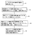
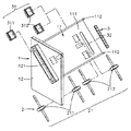
図1〜図3を参照する。図1は、本発明の一実施形態による紙幣処理装置の紙幣位置合わせ方法を示す流れ図である。図2は、本発明の一実施形態による紙幣処理装置を示す斜視図である。図3は、本発明の一実施形態による紙幣処理装置を示す分解斜視図である。図1〜図3から分かるように、本発明の一実施形態による紙幣処理装置は、本体1、伝動装置2及び識別装置3を含む。本体1内部は、傾斜状の通路11を有する。通路11底面111の左右両側には、側板112がそれぞれ設けられる。通路11底面111と水平面との間には、10度〜89度の挟角が形成される。本体1の通路11前方には、パネル12が設けられる。パネル12の表面上には、通路11と連通される挿入口121が形成される。本体1内部の通路11底面111には、伝動装置2及び識別装置3が配置される。伝動装置2は、押圧モジュール21と、押圧モジュール21を駆動させるモータ(図示せず)と、を含む。識別装置3は、紙幣4の通過を検出し、伝動装置2を駆動して紙幣4を開放したり、紙幣4を移動させたりする複数のセンサ31と、紙幣4の真偽及び額面を識別することができるサンプリング識別モジュール32と、を含む。本発明の紙幣処理装置の紙幣位置合わせ方法は、以下(101)〜(105)のステップによって実施される。
Please refer to FIG. FIG. 1 is a flowchart showing a bill alignment method of a bill processing apparatus according to an embodiment of the present invention. FIG. 2 is a perspective view showing a banknote handling apparatus according to an embodiment of the present invention. FIG. 3 is an exploded perspective view showing the banknote handling apparatus according to one embodiment of the present invention. As can be seen from FIGS. 1 to 3, the banknote handling apparatus according to one embodiment of the present invention includes a
(101)ユーザが手で本体1の傾斜状の通路11内に紙幣4を挿入する。
(101) The user inserts the
(102)識別装置3のセンサ31が紙幣4の通過を検出したとき、伝動装置2の押圧モジュール21を起動して紙幣4を押圧する。
(102) When the
(103)押圧モジュール21が紙幣4を通路11内側に進入させた後、ユーザは、手を開放することができる。
(103) After the
(104)押圧モジュール21が紙幣4を所定の距離移動させた後、紙幣4を開放する。紙幣4は、重力の影響によって下方にスライドし、紙幣4の側縁が側板112に当接され、位置合わせされる。
(104) After the
(105)押圧モジュール21が紙幣を再び押圧し、紙幣4を識別装置3の位置まで輸送し、真偽及び額面の識別が行われる。
(105) The
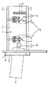
図4〜図8を参照する。図4は、本発明の一実施形態による紙幣処理装置の紙幣位置合わせ方法を示し、紙幣が通路内に挿入されたときの状態を示す斜視図である。図5は、本発明の一実施形態による紙幣処理装置の紙幣位置合わせ方法を示し、紙幣が押圧モジュールに押圧されたときの状態を示す斜視図である。図6は、本発明の一実施形態による紙幣処理装置の紙幣位置合わせ方法を示し、紙幣が内部に進入した後、ユーザの手が開放されたときの状態を示す斜視図である。図7は、本発明の一実施形態による紙幣処理装置の紙幣位置合わせ方法を示し、押圧モジュールが紙幣を開放し、紙幣が通路側辺にスライドしたときの状態を示す斜視図である。図8は、本発明の一実施形態による紙幣処理装置の紙幣位置合わせ方法を示し、押圧モジュールが紙幣を再び押圧し、紙幣を識別装置の位置に輸送し、真偽識別を行うときの状態を示す斜視図である。図4〜図8から分かるように、本発明の一実施形態による紙幣処理装置の本体1は、自動販売機、遊戯機器(図示せず)又は、他の商品又はサービスを販売するシステムに応用することができる。即ち、本体1を自動販売機又は遊戯機器の本体内部に位置決めし、伝動装置2及び識別装置3の回路基板(図示せず)上の複数のコネクタを自動販売機又は遊戯機器の本体と電気的に接続する。これにより、自動販売機及び遊戯機器は、紙幣4の真偽及び額面の識別機能と、紙幣4の受領機能を有することができる。ここで、回路基板上の制御回路が識別装置3の複数のセンサ31と組み合わされ、伝動装置2を制御して紙幣4を移動させる技術と、識別装置3のサンプリング識別モジュール32が紙幣4の真偽及び額面を識別する技術とは、従来技術であるため、ここでは、詳しく述べない。
Reference is made to FIGS. FIG. 4: is a perspective view which shows the banknote alignment method of the banknote processing apparatus by one Embodiment of this invention, and shows a state when a banknote is inserted in the channel | path. FIG. 5: is a perspective view which shows the banknote alignment method of the banknote processing apparatus by one Embodiment of this invention, and shows a state when a banknote is pressed by the press module. FIG. 6 is a perspective view showing a banknote alignment method of the banknote handling apparatus according to the embodiment of the present invention, and showing a state when the user's hand is released after the banknote enters the inside. FIG. 7: is a perspective view which shows the banknote alignment method of the banknote processing apparatus by one Embodiment of this invention, shows a state when a press module open | releases a banknote and a banknote slides to the channel | path side. FIG. 8 shows a banknote alignment method for a banknote processing apparatus according to an embodiment of the present invention, where the pressing module presses the banknote again, transports the banknote to the position of the identification apparatus, and performs authenticity identification. It is a perspective view shown. As can be seen from FIGS. 4 to 8, the
上述の本発明の一実施形態から分かるように、ユーザが手でパネル12の挿入口121から紙幣4を斜めに挿入したとき、紙幣4は、本体1の傾斜状の通路11内に進入する。また、紙幣4が挿入口121と隣り合う変移センサ311の位置まで移動したとき、伝動装置2の押圧モジュール21の第1のローラ群211が起動され、紙幣4を横方向に押圧する。次に、紙幣4が通路11内側に進入したとき、ユーザは、紙幣4が引き込まれたことを感じることができるため、手を開放させることができる。次に、押圧モジュール21の第1のローラ群211が紙幣4を所定の距離移動させた後、紙幣4を開放する。このとき、通路11底面111と水平面との間には、10度〜89度の挟角が形成される上、通路11底面111は、平坦であるため、紙幣4は、重力の影響を受けて下方にスライドし、紙幣4の長手方向の側縁が側板112に当接され、位置合わせされる。次に、押圧モジュール21の第1のローラ群211が再び紙幣4を横向きに押圧し、紙幣4を第2のローラ群212及び識別装置3のサンプリング識別モジュール32の位置まで移動させる。このとき、紙幣4がサンプリング識別モジュール32と隣り合う停止センサ312をトリガし、押圧モジュール21に紙幣4の移動を停止させる。次に、識別装置3のサンプリング識別モジュール32が紙幣4の真偽及び額面の識別を行う。本発明の一実施形態による紙幣処理装置の本体1の通路11と水平面との間には、10度〜89度の挟角が形成されるため、重力の影響により、紙幣4は、下方にスライドし、通路11の側板112上に位置合わせされる。本発明の紙幣処理装置の紙幣位置合わせ方法は、全体の構造が簡単であり、構造が複雑な紙幣位置合わせ装置が必要ない。また、組立が簡単で、コストが安い。また、重力によって紙幣4が下方にスライドして位置合わせされることにより、紙幣4が揃えられ、紙幣の識別を正確に行うことができる。
As can be seen from the above-described embodiment of the present invention, when the user inserts the
識別装置3のサンプリング識別モジュール32は、比較結果に基づき、紙幣4が本物であると判断したとき、伝動装置2の押圧モジュール21を起動し、紙幣4を移動させて通路11を通過させる。また、通路11内部には、盗難防止フック(図示せず)を設けることができ、これにより、犯罪者が工具(針金、テープなど)によって紙幣4を取り出すのが防止される。また、紙幣4が通路11の後方を通過したとき、紙幣移動補助装置(図示せず)が有する紙幣移動ローラ群により、紙幣4が本体内部の通路に進入し、紙幣押圧装置(図示せず)により、紙幣4は、通路に沿って紙幣スタッカ内に移動され、収納される。また、サンプリング識別モジュール32が比較結果に基づき、紙幣4が偽物であると判断したとき、伝動装置2の押圧モジュール21が反対方向に駆動され、偽造紙幣をパネル12上の挿入口121から退出させる。
When the
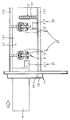
図1、図4及び図9を同時に参照する。図1は、本発明の一実施形態による紙幣処理装置の紙幣位置合わせ方法を示す流れ図である。図4は、本発明の一実施形態による紙幣処理装置の紙幣位置合わせ方法を示し、紙幣が通路内に挿入されたときの状態を示す斜視図である。図9は、本発明の一実施形態による紙幣処理装置の紙幣位置合わせ方法を示し、紙幣が通路内に挿入されたときの状態を示す斜視図である。図1、図4及び図9から分かるように、ユーザがパネル12の挿入口121に紙幣4を挿入させたとき、紙幣4が斜めでも、或いは、通路11上方の側板112から離れていても、挿入口121のガイドにより、紙幣4は、通路11内にスムーズに進入し、伝動装置2の押圧モジュール21が紙幣4を移動させ、紙幣4を所定の距離移動させた後、開放する。このとき、通路11底面111と水平面との間に10度〜89度の挟角が形成されることにより、紙幣4は、重力の影響を受けて下方にスライドし、通路11の側辺の側板112上に位置合わせされる。これにより、従来の紙幣位置合わせ装置のように、2つの挟持アームが紙幣を押圧することにより、紙幣が湾曲したり、丸まったりして紙幣詰まりが発生することがない。また、従来の紙幣位置合わせ装置のように、全体の構造が複雑である上、機械的な損耗が発生しやすいために、使用寿命が短く、組立が複雑であり、価格が高いという欠点がない。また、重力により、紙幣4が下方にスライドして位置合わせされる構造であるため、各国の紙幣、各種有価証券(小切手、株券、権利証書、回数券、商品券など)、各種証明証(身分証、車検証、運転免許証、パスポートなど)などに適用させることができる。
Please refer to FIG. 1, FIG. 4 and FIG. 9 simultaneously. FIG. 1 is a flowchart showing a bill alignment method of a bill processing apparatus according to an embodiment of the present invention. FIG. 4: is a perspective view which shows the banknote alignment method of the banknote processing apparatus by one Embodiment of this invention, and shows a state when a banknote is inserted in the channel | path. FIG. 9: is a perspective view which shows the banknote alignment method of the banknote processing apparatus by one Embodiment of this invention, and shows a state when a banknote is inserted in the channel | path. As can be seen from FIGS. 1, 4, and 9, when the user inserts the
また、本体1の通路11の傾斜角度が小さすぎる場合、紙幣4側面と通路11底面111との間に発生する接触摩擦力が紙幣4の重さよりも僅かに小さくなるだけになるため、下方にスライドしにくくなり、紙幣4側縁が通路11側縁部分の側板112に当接され、位置合わせされるのが困難となる。しかし、通路11の傾斜角度が大きすぎる場合、紙幣4側面部分がスライドする過程において、一時的に通路11から離脱した後、通路11底面111部分に移動するか、或いは、紙幣4と通路11との間に発生する接触摩擦力が小さすぎることにより、紙幣4が側板112上にスライドする速度が速くなりすぎ、紙幣4が湾曲したり、丸まったりする虞がある。また、紙幣4によって材質(硬さなど)及び寸法(縦横の比率、厚さなど)が異なるため、紙幣4と通路11との間に発生する接触摩擦力も変化する。従って、本発明の好適な一実施形態においては、本体1の通路11底面111と水平面との間に、30度〜75度の挟角が形成される上、紙幣4(又は有価証券、証明証など)の種類により、通路11の傾斜角度が調整される。これにより、全体の構造を簡素にすることができ、製作を容易に行うことができる。また、余分な機構を組み合わせる必要がない。紙幣4は、重力の影響によって下方にスライドし、通路11側辺の側板112上に安定的に位置合わせされる。これにより、紙幣4が揃えられ、紙幣の識別を正確に行うことができる。
Further, when the inclination angle of the
即ち、本発明の紙幣処理装置の紙幣位置合わせ方法は、ユーザが本体1の傾斜状の通路11内に紙幣4を斜めに挿入したとき、識別装置3のセンサ31が紙幣4の通過を検出し、伝動装置2の押圧モジュール21を起動して紙幣4を押圧する。次に、紙幣4が通路内側に進入した後、ユーザは、手を開放することができる。次に、押圧モジュール21が紙幣4を所定の距離移動させた後、紙幣4を開放する。このとき、通路11底面111と水平面との間には、10度〜89度の挟角が形成されているため、紙幣4は、重力の影響を受けて下方にスライドし、紙幣4の側縁が側板112に当接され、位置合わせされる。次に、押圧モジュール21が再び紙幣4を押圧し、紙幣4を識別装置3の位置まで移動させ、真偽及び額面の識別を行う。これにより、全体の構造を簡素化することができ、コストが安い。また、重力によって紙幣4が下方にスライドして位置合わせされることにより、紙幣4が揃えられ、紙幣の識別を正確に行うことができる。また、識別時の精度及び安定性を高めることができる。
That is, according to the banknote alignment method of the banknote processing apparatus of the present invention, when the user inserts the
以上の説明は、本発明の好適な実施例を示したものであり、本発明の特許請求の範囲を限定するものではなく、本発明の明細書および図面を運用した簡易な修飾および同等効果の変更は、全て本発明の特許請求の範囲に含まれる。 The above description shows a preferred embodiment of the present invention, and does not limit the scope of the claims of the present invention. The simple modification using the specification and drawings of the present invention and the equivalent effect are described above. All modifications are within the scope of the claims of the present invention.
上述のように、本発明の紙幣処理装置及び紙幣処理装置の位置合わせ方法は、確実にその効果および目的を達成できる。本発明は、高い実用性を有する発明であり、特許出願要件に符合する。 As described above, the banknote processing device and the banknote processing device alignment method of the present invention can reliably achieve the effects and objects thereof. The present invention has high utility and meets the requirements for patent application.
1 本体
11 通路
111 底面
112 側板
12 パネル
121 挿入口
2 伝動装置
21 押圧モジュール
211 第1のローラ群
212 第2のローラ群
3 識別装置
31 センサ
311 変移センサ
312 停止センサ
32 サンプリング識別モジュール
4 紙幣
DESCRIPTION OF
Claims (7)
前記本体に設けられた通路、
前記通路底面の側辺に設けられた側板、
前記通路に設けられ、紙幣を移動させる押圧モジュールを有する伝動装置、及び
前記通路に設けられ、前記紙幣の通過を検出するセンサと前記紙幣の識別を行う識別モジュールを有する識別装置を具備してなり、
前記通路底面が、前記側板の一方が他方よりも下方に位置するように水平面に対して傾斜している紙幣処理装置の紙幣位置合わせ方法であって、
(a)ユーザが手で前記本体の傾斜状の通路内に紙幣を挿入するステップと、
(b)前記センサが前記紙幣の通過を検出したとき、前記押圧モジュールを起動して前記紙幣を押圧するステップと、
(c)前記押圧モジュールが前記紙幣を前記通路内側に進入させた後、前記ユーザは、手を開放するステップと、
(d)前記押圧モジュールが前記紙幣を所定の距離移動させた後、前記紙幣を開放し、前記紙幣は、重力の影響によって下方にスライドし、前記紙幣の側縁が前記側板に当接され、位置合わせされるステップと、
(e)前記押圧モジュールが前記紙幣を再び押圧し、前記紙幣を前記識別装置の位置まで輸送し、真偽及び額面の識別が行われるステップと、
を含むことを特徴とする紙幣処理装置の紙幣位置合わせ方法。 Body,
A passage provided in the main body,
A side plate provided on a side of the bottom surface of the passage,
A transmission device provided in the passage and having a pressing module for moving a bill, and an identification device provided in the passage and having a sensor for detecting passage of the bill and an identification module for identifying the bill. ,
The banknote alignment method of the banknote handling apparatus, wherein the passage bottom surface is inclined with respect to a horizontal plane so that one of the side plates is positioned below the other,
(A) a user manually inserting a banknote into the inclined passage of the main body;
(B) when the sensor detects passage of the banknote, the step of activating the pressing module to press the banknote;
(C) After the pressing module causes the banknote to enter the inside of the passage, the user opens the hand;
(D) After the pressing module moves the banknote a predetermined distance, the banknote is released, the banknote slides downward due to the influence of gravity, and the side edge of the banknote is brought into contact with the side plate, An aligned step;
(E) the pressing module pressing the banknote again, transporting the banknote to the position of the identification device, and performing authenticity and face value identification;
The banknote alignment method of the banknote processing apparatus characterized by including.
前記本体に設けられた通路、
前記通路底面の側辺に設けられた側板、
前記通路に設けられ、紙幣を移動させる押圧モジュールを有する伝動装置、及び
前記通路に設けられ、前記紙幣の通過を検出するセンサと前記紙幣の識別を行う識別モジュールを有する識別装置を有してなり、
前記通路底面は、前記側板の一方が他方よりも下方に位置するように水平面に対して傾斜していることを特徴とする紙幣処理装置。 Body,
A passage provided in the main body,
A side plate provided on a side of the bottom surface of the passage,
A transmission device provided in the passage and having a pressing module for moving a bill, and an identification device provided in the passage and having a sensor for detecting passage of the bill and an identification module for identifying the bill. ,
The banknote processing apparatus, wherein the passage bottom surface is inclined with respect to a horizontal plane so that one of the side plates is positioned below the other.
Priority Applications (1)
| Application Number | Priority Date | Filing Date | Title |
|---|---|---|---|
| JP2011115047A JP2012243218A (en) | 2011-05-23 | 2011-05-23 | Bill processor and bill positioning method of bill processor |
Applications Claiming Priority (1)
| Application Number | Priority Date | Filing Date | Title |
|---|---|---|---|
| JP2011115047A JP2012243218A (en) | 2011-05-23 | 2011-05-23 | Bill processor and bill positioning method of bill processor |
Publications (1)
| Publication Number | Publication Date |
|---|---|
| JP2012243218A true JP2012243218A (en) | 2012-12-10 |
Family
ID=47464825
Family Applications (1)
| Application Number | Title | Priority Date | Filing Date |
|---|---|---|---|
| JP2011115047A Ceased JP2012243218A (en) | 2011-05-23 | 2011-05-23 | Bill processor and bill positioning method of bill processor |
Country Status (1)
| Country | Link |
|---|---|
| JP (1) | JP2012243218A (en) |
Citations (3)
| Publication number | Priority date | Publication date | Assignee | Title |
|---|---|---|---|---|
| JPS61890A (en) * | 1984-06-14 | 1986-01-06 | 富士通株式会社 | Sheet paper handler |
| JP2006004000A (en) * | 2004-06-15 | 2006-01-05 | Aruze Corp | Paper money processing device |
| JP2009053196A (en) * | 2007-08-28 | 2009-03-12 | Mueller Martini Holding Ag | Apparatus for processing printed product |
-
2011
- 2011-05-23 JP JP2011115047A patent/JP2012243218A/en not_active Ceased
Patent Citations (3)
| Publication number | Priority date | Publication date | Assignee | Title |
|---|---|---|---|---|
| JPS61890A (en) * | 1984-06-14 | 1986-01-06 | 富士通株式会社 | Sheet paper handler |
| JP2006004000A (en) * | 2004-06-15 | 2006-01-05 | Aruze Corp | Paper money processing device |
| JP2009053196A (en) * | 2007-08-28 | 2009-03-12 | Mueller Martini Holding Ag | Apparatus for processing printed product |
Similar Documents
| Publication | Publication Date | Title |
|---|---|---|
| JP5184104B2 (en) | Paper sheet processing equipment | |
| WO2009090975A1 (en) | Paper sheet processing device | |
| TWI478108B (en) | The Method of Directing the Location of the | |
| JP6369114B2 (en) | Identification device and medium transaction device | |
| JP2009140345A (en) | Paper money processor | |
| JP6064597B2 (en) | Automatic transaction equipment | |
| WO2009081954A1 (en) | Paper sheet processing device | |
| JP5091619B2 (en) | Banknote handling equipment | |
| JP6532662B2 (en) | Sheet feeding mechanism and sheet processing apparatus | |
| JP5164255B2 (en) | Paper processing equipment | |
| JP2012243218A (en) | Bill processor and bill positioning method of bill processor | |
| JP5209977B2 (en) | Paper sheet processing equipment | |
| JPH0323465B2 (en) | ||
| JPS5839393A (en) | Paper sheet receiver | |
| JPWO2009157249A1 (en) | Bill recognition device | |
| JP5091593B2 (en) | Banknote handling equipment | |
| WO2015129746A1 (en) | Paper currency identifying device | |
| US8469174B2 (en) | Valuable document receiving and alignment method | |
| WO2012042622A1 (en) | Paper sheet conveying device | |
| JP2896527B2 (en) | Bill insertion aid | |
| TW201239769A (en) | Valued paper receiving and alignment method | |
| JP2015172818A (en) | bill identification device | |
| JP6248699B2 (en) | Bill recognition device | |
| JPH0241722Y2 (en) | ||
| KR101853024B1 (en) | Automatic teller machine having the same |
Legal Events
| Date | Code | Title | Description |
|---|---|---|---|
| A131 | Notification of reasons for refusal |
Free format text: JAPANESE INTERMEDIATE CODE: A131 Effective date: 20130212 |
|
| A521 | Written amendment |
Free format text: JAPANESE INTERMEDIATE CODE: A523 Effective date: 20130308 |
|
| A01 | Written decision to grant a patent or to grant a registration (utility model) |
Free format text: JAPANESE INTERMEDIATE CODE: A01 Effective date: 20130423 |
|
| A045 | Written measure of dismissal of application [lapsed due to lack of payment] |
Free format text: JAPANESE INTERMEDIATE CODE: A045 Effective date: 20130827 |