JP2012242102A - Combination balance - Google Patents
Combination balance Download PDFInfo
- Publication number
- JP2012242102A JP2012242102A JP2011109165A JP2011109165A JP2012242102A JP 2012242102 A JP2012242102 A JP 2012242102A JP 2011109165 A JP2011109165 A JP 2011109165A JP 2011109165 A JP2011109165 A JP 2011109165A JP 2012242102 A JP2012242102 A JP 2012242102A
- Authority
- JP
- Japan
- Prior art keywords
- weighed
- objects
- combination
- hopper
- packaging machine
- Prior art date
- Legal status (The legal status is an assumption and is not a legal conclusion. Google has not performed a legal analysis and makes no representation as to the accuracy of the status listed.)
- Granted
Links
- 238000004806 packaging method and process Methods 0.000 claims abstract description 101
- 238000011144 upstream manufacturing Methods 0.000 claims abstract description 42
- 238000007599 discharging Methods 0.000 claims abstract description 11
- 238000012546 transfer Methods 0.000 claims description 24
- 230000004044 response Effects 0.000 claims description 12
- 238000005303 weighing Methods 0.000 abstract description 146
- 238000002360 preparation method Methods 0.000 description 11
- 238000010586 diagram Methods 0.000 description 6
- 238000003780 insertion Methods 0.000 description 5
- 230000037431 insertion Effects 0.000 description 5
- 238000005259 measurement Methods 0.000 description 4
- 241000287828 Gallus gallus Species 0.000 description 2
- 230000006870 function Effects 0.000 description 2
- 238000012858 packaging process Methods 0.000 description 2
- 241000251468 Actinopterygii Species 0.000 description 1
- 241000962514 Alosa chrysochloris Species 0.000 description 1
- 241000238366 Cephalopoda Species 0.000 description 1
- 230000005540 biological transmission Effects 0.000 description 1
- 238000006243 chemical reaction Methods 0.000 description 1
- 230000001934 delay Effects 0.000 description 1
- 230000003111 delayed effect Effects 0.000 description 1
- 238000007689 inspection Methods 0.000 description 1
- 238000004519 manufacturing process Methods 0.000 description 1
- 238000005192 partition Methods 0.000 description 1
- 235000020995 raw meat Nutrition 0.000 description 1
- 235000015170 shellfish Nutrition 0.000 description 1
- 238000004904 shortening Methods 0.000 description 1
- 238000009461 vacuum packaging Methods 0.000 description 1
Images


Landscapes
- Supply Of Fluid Materials To The Packaging Location (AREA)
- Basic Packing Technique (AREA)
Abstract
Description
本発明は、直線状に列設されると共に、被計量物が供給される複数のホッパの組合せを選択して、所定重量範囲の被計量物を包装機等へ投入する組合せ秤に関する。 The present invention relates to a combination weigher that is arranged in a straight line, selects a combination of a plurality of hoppers to which an object to be weighed is supplied, and puts the object to be weighed in a predetermined weight range into a packaging machine or the like.
この種の組合せ秤として、例えば、被計量物の投入を作業者の手によって行う半自動式の組合せ秤がある。この半自動式の組合せ秤は、通常、直線状に列設された複数の計量ホッパと、各計量ホッパの下方に配置された搬送コンベヤとを備えており、作業者が、被計量物を計量ホッパに直接、または、計量ホッパの上方の供給ホッパを介して間接的に投入する。各計量ホッパに投入された被計量物の重量値に基づいて、組合せ演算を行ってその組合せ合計重量である組合せ重量が、目標組合せ重量に等しい、または、目標組合せ重量に最も近い値となる適量組合せを選択すると共に、その適量組合せに選択された計量ホッパの被計量物を、搬送コンベヤに排出する。搬送コンベヤは、複数の計量ホッパが列設された方向である搬送方向に沿って被計量物を搬送し、その搬送終端から後段の装置、例えば、包装機へ投入する(例えば、特許文献1参照)。 As this type of combination weigher, for example, there is a semi-automatic combination weigher in which an object to be weighed is input by an operator's hand. This semi-automatic combination weigher is usually provided with a plurality of weighing hoppers arranged in a straight line and a transfer conveyor arranged below each weighing hopper, and an operator can place an object to be weighed on the weighing hopper. Directly or indirectly through a supply hopper above the weighing hopper. Based on the weight value of the objects to be weighed in each weighing hopper, combination calculation is performed and the combined weight, which is the combined total weight, is equal to or close to the target combination weight. The combination is selected, and the objects to be weighed by the weighing hopper selected for the appropriate combination are discharged to the conveyor. A conveyor conveys an object to be weighed along a conveying direction in which a plurality of weighing hoppers are arranged, and puts it into a subsequent apparatus, for example, a packaging machine from the conveying terminal (see, for example, Patent Document 1). ).
かかる組合せ秤では、上述のように、複数の計量ホッパは、搬送コンベヤの搬送方向に沿って直線状に列設され、適量組合せに選ばれた計量ホッパから被計量物が搬送コンベヤ上に排出され、搬送コンベヤによって前記搬送方向に沿って搬送され、搬送方向の下流側の搬送終端から、順次、後段の装置である包装機へ投入される。 In such a combination weigher, as described above, the plurality of weighing hoppers are arranged in a straight line along the conveying direction of the conveying conveyor, and the objects to be weighed are discharged onto the conveying conveyor from the weighing hopper selected for the appropriate amount combination. Then, it is transported along the transport direction by the transport conveyor, and sequentially fed from the downstream transport end of the transport direction to the packaging machine as the subsequent apparatus.
したがって、適量組合せに選ばれた複数の計量ホッパから排出される被計量物の排出位置によっては、搬送方向の最も上流側に排出される被計量物と、最も下流側に排出される被計量物との距離が長くなり、前記最も下流側の被計量物が搬送コンベヤの搬送終端まで搬送されて包装機へ投入される投入開始時点から前記最も上流側の被計量物が搬送コンベヤの搬送終端まで搬送されて包装機へ投入される投入終了時点までの投入時間が長くなる。 Therefore, depending on the discharge position of the objects to be discharged from the plurality of weighing hoppers selected for the appropriate amount combination, the objects to be discharged to the most upstream side in the transport direction and the objects to be discharged to the most downstream side And the most downstream object to be weighed is transported to the transport end of the transport conveyor and put into the packaging machine, and the most upstream object to be weighed is from the transport conveyor to the transport end of the transport conveyor. The charging time until the end of loading when being transported and loaded into the packaging machine is lengthened.
したがって、包装機では、この長い投入時間に亘って搬送コンベヤからの被計量物の投入を受入れる必要があり、投入受入れのための待ち時間が長くなる。このため、包装機での包装処理のサイクル時間が長くなって、計量包装システム全体としての運転速度が低下するという課題がある。 Therefore, in the packaging machine, it is necessary to accept the input of the objects to be weighed from the transport conveyor over this long charging time, and the waiting time for receiving the charging becomes long. For this reason, the cycle time of the packaging process in a packaging machine becomes long, and there exists a subject that the operation speed as the whole measurement packaging system falls.
本発明は、上述のような課題を解決するために為されたものであって、組合せ秤から後段の装置への被計量物の投入時間の短縮を図ることを目的とする。 The present invention has been made to solve the above-described problems, and an object of the present invention is to shorten the time required for loading an object to be weighed from a combination weigher to a subsequent apparatus.
上記目的を達成するために、本発明では、次のように構成している。 In order to achieve the above object, the present invention is configured as follows.
(1)本発明の組合せ秤は、直線状に列設され、供給される被計量物を保持および排出する複数のホッパと、前記複数のホッパから排出される被計量物を、前記直線状に列設された方向である搬送方向に沿って搬送し、搬送終端から後段の装置へ投入する搬送手段と、組合せ演算を行って、適量組合せの前記ホッパを選択する組合せ演算手段と、前記組合せ演算手段の演算結果に基づいて、前記複数のホッパの被計量物の排出を制御すると共に、前記搬送手段による搬送を制御する制御手段と、前記搬送手段の前記搬送終端から前記後段の装置への被計量物の投入経路に設けられて、前記被計量物の保持および排出が可能な集合ゲートとを備え、前記制御手段は、前記適量組合せに選択されて被計量物を排出する前記ホッパの前記搬送方向の位置に応じて、前記搬送手段の駆動および前記集合ゲートの開閉を制御することによって、前記後段の装置への被計量物の投入を制御する。 (1) The combination weigher of the present invention is arranged in a straight line, and a plurality of hoppers for holding and discharging the supplied objects to be weighed, and the objects to be weighed discharged from the plurality of hoppers are linearly arranged. Conveying means that conveys along a conveying direction that is an arrayed direction, and that is fed into the subsequent apparatus from the conveying end, combination calculating means that performs combination calculation and selects the appropriate amount of the hopper, and combination calculation Based on the calculation results of the means, the discharge of the objects to be weighed by the plurality of hoppers is controlled, the control means for controlling the conveyance by the conveyance means, and the object to be conveyed from the conveyance end of the conveyance means to the subsequent apparatus. An assembly gate provided on a weighing material input path and capable of holding and discharging the object to be weighed, wherein the control means selects the appropriate amount combination and discharges the object to be weighed Direction Depending on the location, by controlling the drive and the opening and closing of the set gate of said conveying means, for controlling the introduction of objects to be weighed to the further apparatus.
ホッパとは、供給される被計量物を保持し、排出するものであればよく、例えば、計量ホッパ、メモリホッパなどのいずれであってもよい。このホッパで被計量物の重量を計量してもよいし、あるいは、計量済の被計量物が供給されるものであってもよい。 The hopper may be any one that holds and discharges an object to be supplied, and may be any of a weighing hopper, a memory hopper, and the like. The weight of the object to be weighed may be measured by this hopper, or a weighed object to be weighed may be supplied.
複数の前記ホッパは、直線状に列設されておればよく、例えば、複数列で直線状に列設されてもよい。 The plurality of hoppers may be arranged in a straight line, for example, may be arranged in a plurality of lines in a straight line.
搬送手段は、直線状に列設された複数のホッパから排出される被計量物を、前記直線状に列設された方向である搬送方向に沿って搬送する。 The conveying means conveys the objects to be discharged discharged from a plurality of hoppers arranged in a line along a conveying direction that is a direction arranged in a line.
後段の装置とは、被計量物の搬送方向の下流側に配置される装置であり、被計量物を包装する包装機が好ましいが、検査装置や振分け装置などであってもよい。 The latter apparatus is an apparatus disposed on the downstream side in the conveyance direction of the object to be weighed, and is preferably a packaging machine for packaging the object to be weighed, but may be an inspection apparatus, a sorting apparatus, or the like.
適量組合せとは、組合せ条件を満たす組合せをいい、例えば、被計量物の重量を組合せた合計重量である組合せ重量が、目標組合せ重量に等しい、あるいは、目標組合せ重量に最も近い許容重量範囲内の組合せをいう。 An appropriate amount combination refers to a combination that satisfies the combination conditions. For example, the combination weight that is the total weight of the weights of the objects to be weighed is equal to the target combination weight or within an allowable weight range closest to the target combination weight. Refers to a combination.
集合ゲートは、搬送手段の搬送終端から後段の装置への被計量物の投入経路に設けられるものであって、そのゲートの開閉によって、被計量物を保持できる一方、保持した被計量物を排出することができ、あるいは、前記搬送終端からの被計量物を通過させことができるものである。 The collecting gate is provided in the input path of the objects to be weighed from the conveyance end of the conveying means to the subsequent apparatus, and the objects to be weighed can be held by opening and closing the gate, and the held objects to be discharged are discharged. Alternatively, the object to be weighed from the end of conveyance can be passed.
本発明の組合せ秤によると、制御手段は、適量組合せに選択されて被計量物を排出するホッパの前記搬送方向の位置に応じて、すなわち、搬送方向のどの位置のホッパから被計量物が排出されるかに応じて、搬送手段の駆動および集合ゲートの開閉を制御することによって、後段の装置への被計量物の投入を制御するようにしている。 According to the combination weigher of the present invention, the control means selects the appropriate amount combination and discharges the object to be weighed according to the position of the hopper in the conveying direction, which discharges the object to be weighed, that is, from which position of the hopper in the conveying direction. Depending on whether or not it is done, the driving of the conveying means and the opening and closing of the collecting gate are controlled to control the input of the object to be weighed into the subsequent apparatus.
したがって、例えば、適量組合せに選択されるホッパの内、搬送方向の最も上流側に位置するホッパと最も下流側に位置するホッパとの距離が長いような場合には、適量組合せのホッパから排出される被計量物を、搬送手段の搬送終端まで搬送してそのまま後段の装置に投入すると、投入時間が長くなるが、本発明によると、搬送手段を駆動して被計量物を搬送終端から排出する一方、集合ゲートを閉じて前記搬送終端から排出される被計量物を保持して集合させると共に、後段の装置への投入開始のタイミングを遅らせ、その後、集合ゲートを開いて、保持した被計量物の後段の装置への投入を開始すると共に、搬送終端から排出される被計量物をそのまま通過させて後段の装置に投入するといったことが可能となる。このように、集合ゲートによって、被計量物を集合させてまとめると共に、後段の装置への投入開始のタイミングを遅らせることによって、後段の装置への被計量物の投入時間を短縮することができ、後段の装置では、被計量物の投入を受入れる待ち時間を短縮することができる。 Therefore, for example, when the distance between the hopper located on the most upstream side in the conveying direction and the hopper located on the most downstream side among the hoppers selected for the appropriate amount combination is long, the hoppers of the appropriate amount combination are discharged. If the object to be weighed is transported to the transport end of the transport means and then put into the subsequent apparatus as it is, the charging time becomes longer. According to the present invention, the transport means is driven to discharge the object to be weighed from the transport end. On the other hand, close the collecting gate to hold and collect the objects to be discharged from the end of conveyance, delay the timing of starting loading into the subsequent apparatus, and then open the collecting gate to hold the objects to be weighed. It is possible to start feeding into the latter apparatus and to pass the object to be weighed discharged from the conveyance end as it is and into the latter apparatus. In this way, the collection gate collects the objects to be weighed together, and by delaying the timing of starting the addition to the subsequent apparatus, the input time of the object to be measured to the subsequent apparatus can be shortened. In the latter apparatus, the waiting time for accepting the input of the object to be weighed can be shortened.
また、逆に、適量組合せに選択されたホッパの内、搬送方向の最も上流側に位置するホッパと最も下流側に位置するホッパとの距離が短い場合には、適量組合せのホッパから排出された被計量物を、搬送手段の搬送終端まで搬送して後段の装置に投入するのに要する時間が短いので、本発明によると、搬送手段を駆動して被計量物を搬送して搬送終端から被計量物を排出すると共に、集合ゲートを開いてそのまま被計量物を、後段の装置へ投入することができ、しかも、搬送手段の駆動開始のタイミングによって後段の装置への投入開始のタイミングを調整することができる。 Conversely, if the distance between the hopper located on the most upstream side in the conveying direction and the hopper located on the most downstream side among the hoppers selected for the appropriate amount combination is short, the hoppers are discharged from the appropriate amount combination hopper. Since the time required for transporting the object to be transported to the transport end of the transport means and putting it into the subsequent apparatus is short, according to the present invention, the transport means is driven to transport the object to be weighed from the transport end. While discharging the weighing object, the collection gate can be opened and the object to be weighed can be loaded into the subsequent apparatus, and the timing of starting loading into the subsequent apparatus is adjusted according to the driving start timing of the conveying means. be able to.
このように、本発明によると、適量組合せに選択されて被計量物を排出するホッパの内、最も上流側に位置するホッパと最も下流側に位置するホッパとの搬送方向の距離が長いような場合には、後段の装置への被計量物の投入時間を短縮することができ、これによって、適量組合せに選択されて被計量物を排出するホッパの搬送方向の位置に拘らず、所要の投入時間内で被計量物を後段の装置へ投入することができる。 As described above, according to the present invention, among the hoppers that are selected as appropriate combinations and discharge the objects to be weighed, the distance in the conveying direction between the hopper located on the most upstream side and the hopper located on the most downstream side is long. In this case, it is possible to shorten the time for putting the object to be measured into the subsequent apparatus, and this makes it possible to select the appropriate amount of combination, regardless of the position in the transport direction of the hopper that discharges the object to be weighed. The object to be weighed can be thrown into the subsequent apparatus within the time.
(2)本発明の好ましい実施態様では、前記搬送手段が、前記ホッパの下方に配設された搬送コンベヤであり、前記後段の装置が、包装機であり、前記制御手段は、前記包装機からの投入要求信号に基づいて、該包装機への被計量物の投入開始および投入時間を制御する。 (2) In a preferred embodiment of the present invention, the transport means is a transport conveyor disposed below the hopper, the latter apparatus is a packaging machine, and the control means is connected to the packaging machine. On the basis of the input request signal, the input start and input time of the object to be weighed into the packaging machine are controlled.
この実施態様によると、包装機からの投入要求信号を基準として、搬送コンベヤの駆動および集合ゲートの開閉を制御して、所要のタイミングで包装機への被計量物の投入を開始することができると共に、所要の投入時間内に被計量物を包装機へ投入することができる。 According to this embodiment, on the basis of the input request signal from the packaging machine, it is possible to control the driving of the conveyor and the opening and closing of the collecting gate, and to start the input of the objects to be weighed into the packaging machine at a required timing. At the same time, the objects to be weighed can be loaded into the packaging machine within the required loading time.
(3)上記(2)の実施態様では、前記制御手段は、前記適量組合せに選択されて被計量物を排出する前記ホッパの内、前記搬送方向の最も上流側のホッパと最も下流側のホッパとの前記搬送方向に沿う距離が、所定長さ以上であるときには、前記投入要求信号に応答して前記搬送コンベヤを駆動して被計量物を搬送すると共に、前記集合ゲートを閉じて前記搬送コンベヤの搬送終端から供給される被計量物を保持した後、前記集合ゲートを開いて被計量物を前記包装機へ投入するようにしてもよい。 (3) In the embodiment of the above (2), the control means is the most upstream hopper and the most downstream hopper in the transport direction among the hoppers that are selected as the appropriate combination and discharge the objects to be weighed. When the distance along the transport direction is equal to or longer than a predetermined length, the transport conveyor is driven in response to the input request signal to transport the objects to be weighed, and the collecting gate is closed to close the transport conveyor After holding the objects to be weighed supplied from the end of conveyance, the collecting gate may be opened to put the objects to be weighed into the packaging machine.
搬送方向の最も上流側のホッパと最も下流側のホッパとの搬送方向の距離は、前記最も上流側のホッパの位置と最も下流側のホッパの位置との搬送方向に沿う距離に対応するものであればよく、前記両ホッパのどの部分を基準とした距離であるかは特に限定されない。例えば、各ホッパの搬送方向の中心位置を基準とし、最も上流側のホッパの搬送方向の中心位置と、最も下流側のホッパの搬送方向の中心位置との間の距離としてもよいし、あるいは、各ホッパの端部の位置を基準とし、最も上流側のホッパの上流側端部の位置と、最も下流側のホッパの下流側端部の位置との間の距離としてもよい。 The distance in the conveyance direction between the most upstream hopper and the most downstream hopper in the conveyance direction corresponds to the distance along the conveyance direction between the position of the most upstream hopper and the position of the most downstream hopper. There is no particular limitation on which part of the hoppers the distance is based on. For example, based on the center position in the transport direction of each hopper, the distance between the center position in the transport direction of the most upstream hopper and the center position in the transport direction of the most downstream hopper, or The distance between the position of the upstream end of the most upstream hopper and the position of the downstream end of the most downstream hopper may be determined based on the position of the end of each hopper.
所定長さは、計量包装システムの運転速度に応じて予め設定されるのが好ましく、運転速度の高速化に応じて、前記所定長さは短くなる。 The predetermined length is preferably set in advance according to the operation speed of the weighing and packaging system, and the predetermined length becomes shorter as the operation speed is increased.
この実施態様によると、例えば、適量組合せに選択されたホッパの内、搬送方向の最も上流側のホッパと最も下流側のホッパとの搬送方向に沿う距離が所定長さ以上であって、ホッパから排出された被計量物を、搬送コンベヤの搬送終端まで搬送して包装機にそのまま投入するのでは、投入時間が長くなるような場合には、搬送コンベヤを駆動して被計量物を搬送終端から排出する一方、集合ゲートを閉じて前記搬送終端から排出される被計量物の一部を保持して集合させると共に、包装機への投入開始のタイミングを遅らせ、その後、集合ゲートを開いて、保持した被計量物の包装機への投入を開始すると共に、前記搬送終端から排出される被計量物をそのまま通過させて包装機へ投入することができるので、包装機への投入時間を短縮することができる。 According to this embodiment, for example, among the hoppers selected for the appropriate amount combination, the distance along the transport direction between the most upstream hopper and the most downstream hopper in the transport direction is a predetermined length or more, and When the discharged objects to be weighed are transported to the end of transport of the transport conveyor and put into the packaging machine as they are, if the charging time is long, the transport conveyor is driven and the objects to be weighed are transported from the end of transport. While discharging, close the collecting gate to hold and collect a part of the objects to be discharged from the end of conveyance, delay the start timing of charging into the packaging machine, and then open and hold the collecting gate Since the weighing object discharged from the end of conveyance can be passed as it is to the packaging machine, the loading time into the packaging machine can be shortened. It is possible.
しかも、集合ゲートでは、搬送コンベヤの搬送終端から排出される被計量物の全てを保持してまとめるのではなく、その一部をまとめて所要の投入時間となるように、投入開始のタイミングを遅らせればよく、これによって、前記搬送終端から排出される被計量物の全てを保持する場合のように集合ゲートを大型にする必要がなく、また、被計量物の全てを保持して排出する際に、集合ゲートで被計量物が詰まって排出できないといった事態が生じるのを防止することができる。 In addition, the collection gate does not hold and collect all the objects to be discharged from the transfer end of the transfer conveyor, but delays the start timing so that a part of them is collected and the required input time is reached. As a result, there is no need to increase the size of the collecting gate as in the case of holding all of the objects to be discharged from the conveyance end, and when holding and discharging all of the objects to be weighed. In addition, it is possible to prevent a situation in which objects to be weighed are clogged at the collecting gate and cannot be discharged.
(4)上記(2),(3)の実施態様では、前記制御手段は、前記適量組合せに選択されて被計量物を排出する前記ホッパの内、前記搬送方向の最も上流側のホッパと最も下流側のホッパとの前記搬送方向に沿う距離が、所定長さ未満であるときには、前記投入要求信号から遅れて前記搬送コンベヤを駆動して被計量物を搬送する一方、前記投入要求信号に応答して前記集合ゲートを開いて前記搬送コンベヤの搬送終端から前記包装機へ被計量物を投入するようにしてもよい。 (4) In the above embodiments (2) and (3), the control means is the most upstream hopper in the transport direction among the hoppers that are selected as the appropriate combination and discharge the objects to be weighed. When the distance along the conveyance direction with the downstream hopper is less than a predetermined length, the conveyance conveyor is driven with a delay from the loading request signal to convey the objects to be weighed, while responding to the loading request signal Then, the collection gate may be opened and the objects to be weighed may be thrown into the packaging machine from the conveyance end of the conveyance conveyor.
この実施態様によると、例えば、適量組合せに選択された被計量物を排出するホッパの内、搬送方向の最も上流側のホッパと最も下流側のホッパとの前記搬送方向に沿う距離が所定長さ未満であって、ホッパから排出された被計量物を、搬送コンベヤの搬送終端まで搬送して包装機へ投入する時間が短い場合には、搬送コンベヤによって搬送終端から被計量物を排出する一方、集合ゲートを開いて、前記搬送終端からそのまま被計量物を包装機へ投入することができると共に、搬送コンベヤの駆動開始のタイミングによって包装機への投入開始のタイミングを調整することができる。 According to this embodiment, for example, the distance along the transport direction between the most upstream hopper and the most downstream hopper in the transport direction among the hoppers that discharge the objects to be weighed selected for an appropriate amount combination is a predetermined length. If it is less than the time, and the time to transport the objects to be weighed discharged from the hopper to the transport end of the transport conveyor and put into the packaging machine is short, the transport object is discharged from the transport end by the transport conveyor, The collection gate can be opened and the objects to be weighed can be put into the packaging machine as they are from the end of the conveyance, and the timing for starting the introduction to the packaging machine can be adjusted by the timing of starting the driving of the conveyance conveyor.
しかも、投入要求信号に応答して集合ゲートを開き、搬送コンベヤの搬送終端から排出される被計量物を保持することなく、そのまま通過させるので、被計量物が、集合ゲートで詰まることがない。 In addition, the collecting gate is opened in response to the input request signal, and the objects to be weighed discharged from the conveying terminal of the conveying conveyor are passed without being held, so that the objects to be weighed are not clogged by the collecting gate.
本発明によると、適量組合せに選択されて被計量物を排出するホッパの搬送方向の位置に応じて、搬送手段の駆動および集合ゲートの開閉を制御することによって、後段の装置への被計量物の投入を制御するので、適量組合せに選択されて被計量物を排出するホッパの内、搬送方向の最も上流側に位置するホッパと最も下流側に位置するホッパとの距離が長い場合には、後段の装置への被計量物の投入時間を短縮することができ、これによって、適量組合せに選択されて被計量物を排出するホッパの搬送方向の位置に拘らず、所要の投入時間内に後段の装置へ被計量物を投入することができ、後段の装置では、被計量物の投入を受入れる待ち時間を短縮することができる。 According to the present invention, the object to be weighed to the subsequent apparatus is controlled by controlling the driving of the conveying means and the opening and closing of the collecting gate according to the position in the conveying direction of the hopper which is selected as an appropriate amount combination and discharges the object to be weighed. Therefore, when the distance between the hopper located on the most upstream side in the conveying direction and the hopper located on the most downstream side is long among the hoppers that are selected as an appropriate combination and discharge the object to be weighed, The input time of the object to be weighed into the latter apparatus can be shortened, so that the rear stage is within the required input time regardless of the position in the transport direction of the hopper that is selected as an appropriate combination and discharges the object to be weighed. The object to be weighed can be loaded into the apparatus, and the waiting time for receiving the object to be weighed can be shortened in the latter apparatus.
以下、図面によって本発明の実施形態について詳細に説明する。 Hereinafter, embodiments of the present invention will be described in detail with reference to the drawings.
(実施形態1)
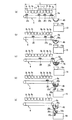
図1は、本発明の一実施形態に係る半自動式の組合せ秤の概略平面図であり、図2はその正面図であり、図3はその側面図である。
(Embodiment 1)
FIG. 1 is a schematic plan view of a semi-automatic combination weigher according to an embodiment of the present invention, FIG. 2 is a front view thereof, and FIG. 3 is a side view thereof.
この実施形態の組合せ秤1は、被計量物の供給を人手によって行う半自動式の組合せ秤であり、被計量物は特に限定されないが、鶏肉(ブロイラー)等の生肉、イカやカツオ等の魚介類等、粘着性があり単重(1個あたりの重さ)が比較的大きい被計量物の計量に好適である。
The
この実施形態の半自動式の組合せ秤1は、被計量物の組合せ計量を行う本体2と、当該秤1の運転制御用パラメータ、例えば、目標組合せ重量、許容上限値などの設定や作動状況の表示を行う操作設定表示部3と、本体2から排出される被計量物を搬送する搬送コンベヤ4とを備えている。
The
本体2は、基台5と、この基台5の上部に位置して平面視が略矩形状の天板6とを備える。天板6には、図1に示すように、作業者が被計量物を掴んで投入するための複数、この実施形態では9個の投入口121〜129が、中央部に所定間隔で直線状に列設されている。
The
各投入口121〜129の下方には、それぞれ個別に対応する供給ホッパ71〜79が配設されている。各供給ホッパ71〜79の下方には、それぞれ個別に対応する計量ホッパ91〜99が、直線状に列設されている。これら計量ホッパ91〜99はそれぞれ基台5に支持されている。基台5の側部には、図3に示すように、9個の計量センサ101〜109が格納されている。これら計量センサ101〜109は、例えば、ロードセルからなり、各計量ホッパ91〜99に個別に連結されている。
Under the respective inlets 12 1 to 12 9 , supply hoppers 7 1 to 7 9 corresponding to the respective inlets are arranged. Below each feed hopper 7 1-7 9, the weighing
各計量ホッパ91〜99は、各供給ホッパ71〜79から供給される被計量物をそれぞれ収容して計量するため、前後方向(図3の左右方向、図1の上下方向)に、手前側1室、奥側1室で合計2室の独立した計量室111a〜119a;111b〜119bをそれぞれ備えている。
Each weighing
これら計量室111a〜119a;111b〜119bは、中央の区画壁351〜359によって仕切られている。基台5には、後述する制御回路(図示せず)が収納されている。
These measuring chambers 11 1 a to 11 9 a; 11 1 b to 11 9 b are partitioned by central partition walls 35 1 to 35 9 . The
各供給ホッパ71〜79は、図3に示すように、エアシリンダ(図示せず)によって開閉駆動される一対のゲート131a〜139a;131b〜139bをそれぞれ有している。これらゲート131a〜139a;131b〜139bはそれぞれ独立して開閉が可能であり、いずれか一方のゲート131a〜139a(または131b〜139b)を開くことで、被計量物を計量ホッパ91〜99のいずれか一方の計量室111a〜119a(または111b〜119b)に選択的に供給できるように構成されている。 As shown in FIG. 3, each of the supply hoppers 7 1 to 7 9 has a pair of gates 13 1 a to 13 9 a; 13 1 b to 13 9 b that are driven to open and close by an air cylinder (not shown). doing. These gates 13 1 a to 13 9 a; 13 1 b to 13 9 b can be opened and closed independently, and one of the gates 13 1 a to 13 9 a (or 13 1 b to 13 9 b) Is configured so that an object to be weighed can be selectively supplied to one of the weighing chambers 11 1 a to 11 9 a (or 11 1 b to 11 9 b) of the weighing hoppers 9 1 to 9 9. ing.
各計量ホッパ91〜99は、上述のように各計量センサ101〜109にそれぞれ連結されているので、被計量物が供給ホッパ71〜79から計量ホッパ91〜99のいずれか一方の計量室111a〜119a(または111b〜119b)に供給されると、各計量センサ101〜109によって検出される重量値の変化に基づいて、各計量室111a〜119a(または111b〜119b)に供給される被計量物を計量することができる。 Since the weighing hoppers 9 1 to 9 9 are respectively connected to the weighing sensors 10 1 to 10 9 as described above, the objects to be weighed are fed from the supply hoppers 7 1 to 7 9 to the weighing hoppers 9 1 to 9 9 . When supplied to any one of the weighing chambers 11 1 a to 11 9 a (or 11 1 b to 11 9 b), each of the weighing chambers 11 1 a to 11 9 a is changed based on a change in weight value detected by each weighing sensor 10 1 to 10 9 . The objects to be weighed supplied to the measuring chambers 11 1 a to 11 9 a (or 11 1 b to 11 9 b) can be measured.
計量ホッパ91〜99は、前後方向の手前側の計量室111a〜119aには手前側のゲート231a〜239a、奥側の計量室111b〜119bには奥側のゲート231b〜239bをそれぞれ有している。これらゲートは、図示しないエアシリンダによって開閉駆動される。なお、ゲートの開閉はエアシリンダに限らず、例えば、モータを用いてもよい。
Weighing
これら手前側のゲート231a〜239aと、奥側ゲート231b〜239bとは、それぞれ独立して開閉が可能であり、一方のゲート231a〜239aを開くことで、対応する一方の計量室111a〜119aから被計量物を排出し、また、他方のゲート231b〜239bを開くことで、他方の計量室111b〜119bから被計量物を排出する。なお、これら両側のゲート231a〜239a;231b〜239bを同時に開けば、両側の計量室111a〜119a;111b〜119bから被計量物が排出される。 The front gates 23 1 a to 23 9 a and the rear gates 23 1 b to 23 9 b can be opened and closed independently, and one of the gates 23 1 a to 23 9 a is opened. in, then discharge the objects to be weighed from the corresponding one of the measuring chamber 11 1 a~11 9 a, also, by opening the other gate 23 1 b~23 9 b, the other weighing chamber 11 1 b~11 9 The object to be weighed is discharged from b. If the gates 23 1 a to 23 9 a; 23 1 b to 23 9 b on both sides are opened at the same time, the objects to be weighed are measured from the weighing chambers 11 1 a to 11 9 a; 11 1 b to 11 9 b on both sides. Discharged.
搬送コンベヤ4は、基台5により支持され、計量ホッパ91〜99の直線状の列設方向と被計量物の搬送方向(図1,図2の左右方向)とが平行になるように計量ホッパ91〜99の下方に配設されている。
搬送コンベヤ4は、計量ホッパ91〜99の各計量室111a〜119a;111b〜119bから排出される被計量物を、搬送方向の下流側(図1,図2の右側)へ搬送し、その搬送終端4aからその下方に配置されている後段の包装機(図示せず)へ投入する。
The
この組合せ秤では、一定時間間隔の組合せ演算のタイミングで、計量センサ101〜109による計量が完了している計量ホッパ91〜99の各計量室111a〜119a,111b〜119bの被計量物の重量を種々に組合せ、これら組合せの中から組合せ重量(合計重量)が、目標組合せ重量に等しい、あるいは、目標組合せ重量に最も近い所定重量範囲内にある適量組合せを探す、すなわち、組合せ演算を行う。そして、組合せが成立して、選択された適量組合せの被計量物が収容されている計量ホッパ91〜99の各計量室111a〜119a,111b〜119bのゲート231a〜239a,231b〜239bを開いて、下方の搬送コンベヤ4上に排出し、搬送コンベヤ4によって、該搬送コンベヤ4の搬送終端4a側に配置されている包装機に搬送投入し、包装機で被計量物が包装される。
In this combination weigher, the weighing chambers 11 1 a to 11 9 a and 11 1 of the weighing hoppers 9 1 to 9 9 have been weighed by the weighing sensors 10 1 to 10 9 at the timing of the combination calculation at regular time intervals. Various combinations of the weights of the objects to be weighed b to 11 9 b, and the combination weight (total weight) among these combinations is an appropriate amount within the predetermined weight range that is equal to or closest to the target combination weight Search for a combination, that is, perform a combination operation. Then, the combination is established, and the gates of the weighing chambers 11 1 a to 11 9 a and 11 1 b to 11 9 b of the weighing hoppers 9 1 to 9 9 in which the objects to be weighed in the proper combination selected are accommodated. 23 1 a to 23 9 a, 23 1 b to 23 9 b are opened, discharged onto the
このようにして、被計量物の排出が行われると、空になった計量ホッパ91〜99の計量室111a〜119a,111b〜119bには、その上方にある供給ホッパ71〜79から被計量物が供給される。その結果、空になった供給ホッパ71〜79には、人手によって被計量物が供給される。
In this manner, the discharge of the objects to be weighed, the weighing chamber 11 1 a~11 9 a, 11 1 b~11 9 b of the weighing
この実施形態では、搬送コンベヤ4の搬送終端4aから排出される被計量物の包装機への投入時間を短縮できるように、搬送コンベヤ4の搬送終端4aから、その下方の包装機へ至る被計量物の投入経路には、集合ゲート45を設けている。
In this embodiment, in order to shorten the charging time of the objects to be weighed discharged from the conveying terminal 4a of the conveying
この集合ゲート45は、基台5に支持されており、図2に示すように、被計量物を収容する収容部45aと、ゲート部45bとを備えており、ゲート部45bを閉じて、搬送コンベヤ4の搬送終端4aから排出される被計量物を収容部45aに保持し、また、前記ゲート部45bを開いて、収容部45aに保持した被計量物を包装機へ投入し、あるいは、前記搬送終端4aから排出される被計量物をそのまま通過させる。
The
図4は、この実施形態の制御系統を示すブロック図であり、上述の図1〜図3に対応する部分には、同一の参照符号を付す。 FIG. 4 is a block diagram showing the control system of this embodiment, and parts corresponding to those in FIGS. 1 to 3 are given the same reference numerals.
この実施形態の組合せ秤1は、制御回路22を備えており、この制御回路22は、各部を制御する制御手段としての機能を有すると共に、組合せ演算を行う組合せ演算手段としての機能を有するCPU部24と、制御プログラムが格納されていると共に、計量値などが格納されるメモリ部25と、各供給ホッパ71〜79の一対の各ゲート131a〜139a;131b〜139bを開閉する供給ホッパゲート駆動回路部26と、各計量ホッパ91〜99の一対の各ゲート231a〜239a;231b〜239bを開閉する計量ホッパゲート駆動回路部27と、各計量センサ101〜109からのアナログ信号をデジタル信号に変換するA/D変換回路部29と、搬送コンベヤ4を駆動するコンベヤ駆動回路部31と、包装機に接続されたI/O回路部32と、集合ゲート45のゲート部45bの開閉を制御する集合ゲート駆動回路部28とを有している。
The
A/D変換回路部29からのデジタル信号は、CPU部24において、計量値に変換される。CPU部24は、計量ホッパ91〜99の各計量室111a〜119a,111b〜119bに供給された被計量物の重量を計量し、一定の時間間隔の組合せ演算のタイミング時に、上述の組合せ演算を行う。組合せが成立し、適量組合せがあったときには、計量ホッパゲート駆動回路部27を介して適量組合せの計量ホッパ91〜99の計量室111a〜119a;111b〜119bのゲート231a〜239a;231b〜239bの開閉を制御し、選択された計量ホッパ91〜99の計量室111a〜119a;111b〜119bの被計量物を、搬送コンベヤ4に排出させる。
The digital signal from the A / D
すなわち、CPU部24は、組合せ演算を行って、組合せが成立すると、適量組合せとして選択された計量ホッパ91〜99の計量室111a〜119a;111b〜119bのゲート231a〜239a;231b〜239bを開いて、被計量物を搬送コンベヤ4へ排出し、包装機からの投入要求信号の入力に応答して、後述のように搬送コンベヤ4の駆動および集合ゲート45の開閉を制御して、被計量物を包装機へ投入する。CPU部24は、搬送コンベヤ4による被計量物の包装機への投入が終了すると、搬送コンベヤ4の駆動を停止すると共に、包装機に対して投入完了信号を送信する。
That is, the
また、組合せが成立しない重量不良の被計量物の場合には、搬送コンベヤ4に排出し、包装機とは逆方向に搬送して回収容器に搬出する、いわゆる、リジェクトを行う。
In addition, in the case of an object to be weighed with a poor weight that cannot be combined, a so-called rejection is performed in which it is discharged to the
次に、この実施形態における被計量物の搬送及び包装機への投入の動作について説明する。 Next, the operation of conveying an object to be weighed and putting it into a packaging machine in this embodiment will be described.
この実施形態の包装機は、組合せ秤1から投入される被計量物を受け取って、予め成形された袋に充填して真空パックを行う給袋式の包装機である。
The packaging machine according to this embodiment is a bag-feeding type packaging machine that receives an object to be weighed from the
この包装機は、上述の投入要求信号を送信してから投入の受入れの準備が整うまでの一定の準備時間が経過した後、組合せ秤1からの被計量物の投入の受入れを許可する投入許可期間となる。この投入許可期間の長さは、組合せ秤1及び包装機からなる計量包装システムの運転速度に応じて設定される。この実施形態では、計量包装システムを、所望の高速で運転するために、投入許可期間は、比較的短く設定される。
This packaging machine permits the acceptance of the input of an object to be weighed from the
この実施形態では、組合せ演算によって適量組合せとして選択された計量ホッパ91〜99の搬送方向(図1,図2の左右方向)における位置に応じて、搬送コンベヤ4の駆動を制御すると共に、集合ゲート45の開閉を制御することによって、包装機からの投入要求信号に基づいて、前記投入許可期間内に、適量組合せの計量ホッパ91〜99の計量室111a〜119a;111b〜119bから排出された被計量物を包装機へ投入するようにしている。なお、各計量ホッパ91〜99は、前後方向に2つの計量室111a〜119a;111b〜119bをそれぞれ有しているが、両計量室の搬送方向における位置は同じ、例えば、計量ホッパ91の手前側の計量室111aと奥側の計量室111bとの搬送方向における位置は同じであるので、簡略化のため以下の説明では、計量室を明示することなく、搬送方向に沿う1列の計量ホッパ91〜99として説明する。
In this embodiment, the conveyance direction of the weighing
この実施形態では、適量組合せに選択されて被計量物を排出する計量ホッパ91〜99の内、搬送方向の最も上流側の計量ホッパと最も下流側の計量ホッパとの搬送方向に沿う距離が、所定長さ以上であるか否かに応じて、搬送コンベヤ4及び集合ゲート45の制御を異ならせている。この所定長さは、例えば、包装機の前記投入許可期間内において、搬送コンベヤ4によって搬送できる距離以内に予め設定されるのが好ましい。
In this embodiment, among the weighing hoppers 9 1 to 99 9 that are selected as an appropriate amount combination and discharge an object to be weighed, a distance along the conveying direction between the most upstream weighing hopper and the most downstream weighing hopper in the conveying direction. However, the control of the
先ず、組合せ演算によって適量組合せに選択されて被計量物を排出する計量ホッパ91〜99の内、搬送方向の最も上流側の計量ホッパと最も下流側の計量ホッパとの搬送方向に沿う距離が、所定長さ以上である場合について、図5及び図6に基づいて説明する。 First, among the weighing hoppers 9 1 to 99 9 that are selected as an appropriate combination by the combination calculation and discharge the objects to be weighed, the distance along the conveying direction between the most upstream weighing hopper and the most downstream weighing hopper in the conveying direction Will be described based on FIG. 5 and FIG. 6.
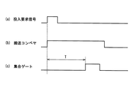
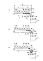
図5は、組合せ演算によって適量組合せとして選択された計量ホッパ91〜99から被計量物を搬送コンベヤ4に排出し、搬送コンベヤ4によって搬送終端4aまで搬送し、集合ゲート45を介して包装機19のシュート19aに投入するまでの動作の一例を示す概略図である。図6は、図5のタイムチャートであり、同図(a)は投入要求信号を、同図(b)は搬送コンベヤ4の駆動状態を、同図(c)は集合ゲート10の開閉状態をそれぞれ示している。図6(b)において、ハイレベルは搬送コンベヤ4を駆動している状態を、図6(c)において、ハイレベルは集合ゲート45の開放状態をそれぞれ示している。
5, to discharge the objects to be weighed to the
図5において、搬送コンベヤ4の長さである搬送距離をL、上記所定長さをL1としている。この実施形態では、所定長さL1は、例えば、搬送方向に沿う計量ホッパ5個分の上流側の端部から下流側の端部までの長さとしている。
In FIG. 5, the conveyance distance which is the length of the
図5の例では、同図(a)に示すように、組合せ演算によって適量組合せに選択された計量ホッパ91,95,97,99から被計量物201,205,207,209が搬送コンベヤ4上に排出される。この場合、適量組合せに選択された計量ホッパ91,95,97,99の内、最も上流側の計量ホッパ91の上流側の端部と最も下流側の計量ホッパ99の下流側の端部との搬送方向に沿う距離は、計量ホッパ9個分であり、上述の計量ホッパ5個分に対応する所定長さL1以上である。
In the example of FIG. 5, as shown in FIG. 5A, the weighing objects 20 1 , 20 5 , 20 7 from the weighing hoppers 9 1 , 9 5 , 9 7 , 9 9 selected as an appropriate combination by the combination calculation. , 20 9 are discharged onto the
このように搬送方向の最も上流側の計量ホッパ91と最も下流側の計量ホッパ99との距離が、所定長さL1以上である場合には、搬送コンベヤ4によって最も下流側の被計量物209をその搬送終端4aから包装機19に直接投入してから最も上流側の被計量物201をその搬送終端4aから包装機19へ直接投入するまでの投入時間は、包装機19の上述の投入許可期間を上回ることになり、したがって、投入時間を短縮する必要がある。また、包装機19の投入要求信号から投入の受入れの準備が整うまでの一定の準備時間が経過した後に、包装機19への投入を開始する必要がある、すなわち、投入開始のタイミングを調整する必要がある。
The distance between the weighing hopper 9 9 Thus the most upstream side of the weighing hopper 9 1 the most downstream side in the transport direction, if more than a predetermined length L1, the most downstream side of the objects to be weighed by the
そこで、この実施形態では、図6(a)に示すハイレベルの投入要求信号に応答して、図6(b)に示すように、搬送コンベヤ4を直ちに駆動して排出された被計量物201,205,207,209の搬送を開始する。このとき、包装機19の前記準備時間が経過するまでは、被計量物20を包装機19へ投入しないようにすると共に、投入時間を短縮するために、集合ゲート45は、図6(c)に示すように閉じられている。
Therefore, in this embodiment, in response to the high-level input request signal shown in FIG. 6A, as shown in FIG. 6B, the conveyor 20 is immediately driven and discharged. 1, 20 5, 20 7, starts 20 9 transport of. At this time, until the preparation time of the
したがって、図5(b),(c)に示すように、搬送コンベヤ4が駆動されて被計量物201,205,207,209が搬送され、下流寄りの被計量物209,207が、搬送終端4aから排出され、集合ゲート45に保持されてまとめられる。
Thus, FIG. 5 (b), the (c), the
そして、図6(c)に示すように、投入要求信号の受信から一定の待機時間Tが経過すると、集合ゲート45を開く。この待機時間Tは、包装機19が、投入要求信号を送信して投入の受入れの準備が整うまでの一定の準備時間以上の時間となっている。したがって、待機時間Tが経過した時点では、包装機19は、被計量物の投入の受入れを許可する投入許可期間となっている。
Then, as shown in FIG. 6C, when a certain waiting time T has elapsed since the receipt of the insertion request signal, the
また、この待機時間Tは、例えば、図5(a)に示される、搬送距離Lから所定長さL1を減算した距離(L−L1)を、搬送するのに要する時間となっている。したがって、仮に、投入要求信号に応答して直ちに搬送コンベヤ4の駆動を開始すると共に、集合ゲート45を開いたとすると、待機時間Tが経過した時点では、下流寄りの4個の計量ホッパ96〜99から排出された被計量物が、包装機19に投入されることになる。
Further, the waiting time T is a time required for transporting, for example, a distance (L-L1) obtained by subtracting a predetermined length L1 from the transport distance L shown in FIG. Therefore, assuming that the driving of the
この実施形態では、上述のように、待機時間Tが経過して集合ゲート45を開くので、図5(d),(e)に示すように、集合ゲート45に保持されていた被計量物209,207が包装機19に投入されると共に、後続の上流寄りの被計量物205,201も集合ゲート45を通過して包装機19に投入される。
In this embodiment, as described above, since the waiting time T has elapsed and the collecting
このように組合せ演算によって適量組合せに選択された計量ホッパ91,95,97,99の内、最も上流側の計量ホッパ91の上流側の端部と最も下流側の計量ホッパ99の下流側の端部との距離が、所定長さL1以上であるときには、包装機19からの投入要求信号に応答して搬送コンベヤ4を駆動して被計量物を搬送して搬送終端4aから排出すると共に、集合ゲート45を閉じて前記搬送終端4aから排出される下流寄りの被計量物209,207を保持して集合させると共に、包装機19への投入開始のタイミングを遅らせる。
Thus the weighing hopper 9 is selected optimal combination by combination calculation 1, 9 5, 9 7, 9 9 among the most downstream weighing the end portion on the most upstream side of the weighing hopper 9 1 upstream hopper 9 When the distance from the downstream end of 9 is equal to or longer than the predetermined length L1, the conveying
そして、包装機19の投入の受入れの準備が整う準備時間に対応する待機時間Tが経過して投入許可期間になったときには、集合ゲート45を開いて保持していた被計量物209,207を排出して包装機19への投入を開始し、後続の上流寄りの被計量物205,201も集合ゲート45を通過させて包装機19へ投入するので、集合ゲート45を開いて被計量物209の投入を開始して最後の被計量物201の投入を終了するまでの投入時間を短縮して投入許可期間内に投入することができる。
Then, when the waiting time T corresponding to the preparation time when preparation for receiving the filling of the
しかも、集合ゲート45は、搬送コンベヤ4の搬送終端4aから排出される被計量物201,205,207,209の全てを保持するのではなく、待機時間Tが経過するまでに搬送コンベヤ4の搬送終端4aから排出される下流寄りの被計量物207,209を保持すればよい。したがって、全ての被計量物を保持する場合のように、集合ゲート45の収容容量を大きくする必要がなく、また、集合ゲート45を開いて保持した被計量物を排出する際に、被計量物が集合ゲート45で詰まって排出できないといった事態が生じるのを防止することができる。
Moreover, the
また、集合ゲート45を開いた後には、保持していた下流寄りの被計量物207,209が集合ゲート45から排出されると共に、後続の上流寄りの被計量物205,201が、集合ゲート45を通過するので、仮に、集合ゲート45で保持されていた被計量物207,209が排出の際に詰まったとしても、落下する後続の被計量物205,201の衝撃によって、詰まりを解消することができる。
Further, after opening the
次に、組合せ演算によって適量組合せに選択された計量ホッパの内、最も上流側の計量ホッパの上流側の端部と最も下流側の計量ホッパの下流側の端部との搬送方向に沿う距離が、所定長さL1未満である場合について、上述の図5及び図6にそれぞれ対応する図7及び図8に基づいて説明する。 Next, among the weighing hoppers selected as appropriate combinations by the combination calculation, the distance along the transport direction between the upstream end of the most upstream weighing hopper and the downstream end of the most downstream weighing hopper is The case where the length is less than the predetermined length L1 will be described with reference to FIGS. 7 and 8 corresponding to FIGS. 5 and 6, respectively.
図7は、組合せ演算によって適量組合せとして選択された計量ホッパ96〜99から被計量物206〜209を搬送コンベヤ4に排出し、搬送コンベヤ4によって搬送終端4aまで搬送し、集合ゲート45を介して包装機19のシュート19aに投入するまでの動作の一例を示す概略図であり、図8は、図7のタイムチャートである。
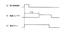
Figure 7 is to discharge the objects to be weighed 20 6-20 9 from the weighing hopper 9 6-9 9 selected as optimal combination by combination calculation in
この例では、図7(a)に示すように、組合せ演算によって適量組合せとして選択された計量ホッパ96,97,98,99から被計量物206,207,208,209が搬送コンベヤ4上に排出される。この場合、最も上流側の計量ホッパ86の上流側の端部と最も下流側の計量ホッパ89の下流側の端部との距離は、計量ホッパ4個分であり、計量ホッパ5個分に対応する所定長さL1未満である。
In this example, as shown in FIG. 7A, the weighing objects 20 6 , 20 7 , 20 8 , 20 from the weighing hoppers 9 6 , 9 7 , 9 8 , 9 9 selected as an appropriate amount combination by the combination calculation. 9 is discharged onto the
この場合は、搬送コンベヤ4によって最も下流側の被計量物209をその搬送終端4aから包装機19に直接投入してから最も上流側の被計量物206をその搬送終端から包装機19へ直接投入するまでに要する投入時間は、包装機19の上述の投入許可期間に対応する時間内に収まることになるので、集合ゲート10で被計量物を保持して投入時間を短縮する必要はない。しかしながら、包装機19の投入要求信号から投入の受入れの準備が整う準備時間に対応する上述の待機時間Tが経過した後に投入を開始する必要がある、すなわち、投入開始のタイミングを調整する必要がある。
In this case, the most upstream side of the objects to be weighed 20 6 from the transfer terminal end most downstream side of the objects to be weighed 20 9 was charged directly to the
上述の図5及び図6の場合には、被計量物の投入時間を短くするために、集合ゲート45を閉じて下流寄りの被計量物を保持するようにしている。したがって、図5(c),(d)に示されるように、集合ゲート45を開いて包装機19への被計量物の投入を開始した時点では、被計量物が既に集合ゲート45に保持されている。
In the case of FIG. 5 and FIG. 6 described above, in order to shorten the input time of the objects to be weighed, the
これに対して、図7及び図8の場合は、集合ゲート45で被計量物を保持して投入時間を短縮する必要はなく、被計量物は、集合ゲート45に保持されない。
On the other hand, in the case of FIG. 7 and FIG. 8, it is not necessary to hold the objects to be weighed by the collecting
このため、図7(a)に示すように、最も下流寄りの被計量物209を、搬送コンベヤ4の搬送終端4aから集合ゲート45までの距離L2を移送するのに要する移送時間T1を考慮するようにしている。
Therefore, as shown in FIG. 7 (a), the most downstream toward the objects to be weighed 20 9, taking into account the transport time T1 required to transfer the distance L2 from the transfer
具体的には、投入要求信号の受信から上述の待機時間Tが経過したときには、最も下流側の被計量物209が集合ゲート10の位置まで移送されているようにするために、待機時間Tから移送時間T1を減算した待ち時間(T−T1)が、経過したときに、搬送コンベヤ4の駆動を開始するようにしている。
More specifically, when the waiting time T described above from the reception of the input request signal has elapsed, for the most downstream side of the objects to be weighed 20 9 is to be transferred to the position of the set gate 10, waiting time T When the waiting time (T-T1) obtained by subtracting the transfer time T1 from the time has elapsed, the driving of the
すなわち、図8(a)の投入要求信号に応答して、図8(c)に示すように、集合ゲート45を直ちに開く一方、搬送コンベヤ4は、図8(b)に示すように、投入要求信号の受信から前記待ち時間(T−T1)が経過した後、駆動を開始して搬送終端4aから被計量物を排出するようにしている。
That is, in response to the input request signal in FIG. 8 (a), the collecting
したがって、投入要求信号から待ち時間(T−T1)が経過すると、図7(b)に示されるように、搬送コンベヤ4の駆動が開始されて被計量物206,207,208,209が搬送され、搬送終端4aから排出され、図7(c)に示すように、開いている集合ゲート45を通過して包装機19に投入される。
Therefore, when the waiting time (T-T1) elapses from the input request signal, as shown in FIG. 7B, the driving of the
このように組合せ演算によって適量組合せに選択された計量ホッパ91,95,97,99の内、最も上流側の計量ホッパの上流側の端部と最も下流側の計量ホッパの下流側の端部との搬送方向に沿う距離が、所定長さL1未満であるときには、包装機19からの投入要求信号に応答して集合ゲート45を直ちに開く一方、包装機19の準備時間が経過して投入許可期間になったときに、最も下流側の被計量物209が包装機19に投入されるように、搬送コンベヤ4の駆動の開始を、待ち時間(T−T1)遅らせるので、上述の図5及び図6の場合と同様に、包装機19の投入許可期間の開始に応じたタイミングで、包装機19へ被計量物209の投入を開始し、投入許可期間内に全ての被計量物206,207,208,209を投入することができる。
Thus the weighing hopper 9 is selected optimal combination by combination calculation 1, 9 5, 9 7, 9 9 of the downstream side of the most downstream side of the weighing hopper and upstream of the end of the most upstream side of the weighing hoppers When the distance along the conveying direction with the end of the bag is less than the predetermined length L1, the
しかも、集合ゲート45では、被計量物206,207,208,209を全く保持しないので、被計量物が集合ゲート45で詰まって排出できないといった事態が生じることがない。
Moreover, the
以上のように、この実施形では、適量組合せに選択されて被計量物を排出する計量ホッパ91〜99の内、搬送方向の最も上流側の計量ホッパと最も下流側の計量ホッパとの搬送方向に沿う距離が、所定長さL1以上であるときには、包装機19への被計量物の投入時間を短縮し、前記搬送方向に沿う距離が所定長さL1未満であるときと同様に、包装機19の投入許可期間内に被計量物を投入することができる。
As described above, in this embodiment, among the weighing hoppers 9 1 to 99 9 that are selected as an appropriate combination and discharge the objects to be weighed, the most upstream weighing hopper and the most downstream weighing hopper in the conveying direction. When the distance along the transport direction is equal to or longer than the predetermined length L1, the time for putting the object to be weighed into the
したがって、包装機19の投入許可期間を、適量組合せに選択されて被計量物を排出する計量ホッパ91〜99の内、搬送方向の最も上流側の計量ホッパと最も下流側の計量ホッパとの搬送方向に沿う距離が、所定長さL1以上であるときを想定して長くしておく必要がない。これによって、包装機19の投入受入れのための待ち時間を短くして包装処理のサイクル時間を短縮することができ、その分、計量包装システム全体としての運転速度を高めて生産量を向上させることができる。
Therefore, among the weighing hoppers 9 1 to 99 9 , which are selected as an appropriate combination for the input permission period of the
しかも、集合ゲート10で被計量物が詰まるのを有効に防止することができる。 Moreover, it is possible to effectively prevent the objects to be weighed from being clogged at the collecting gate 10.
上述の実施形態では、組合せ演算によって適量組合せに選択された計量ホッパの内、最も上流側の計量ホッパの上流側の端部と最も下流側の計量ホッパの下流側の端部との搬送方向に沿う距離が、所定長さL1未満である場合には、投入要求信号に応答して集合ゲート45を開く一方、搬送コンベヤ4の駆動開始のタイミングによって、包装機19への被計量物の投入開始のタイミングを調整したけれども、本発明の他の実施形態として、投入要求信号に応答して搬送コンベヤ4を駆動する一方、集合ゲート45を閉じて被計量物を保持し、集合ゲート45を開くタイミングによって包装機19への被計量物の投入開始のタイミングを調整するようにしてもよい。
In the above-described embodiment, among the weighing hoppers selected as appropriate combinations by the combination calculation, in the transport direction between the upstream end of the most upstream weighing hopper and the downstream end of the most downstream weighing hopper. When the distance along the line is less than the predetermined length L1, the
(実施形態2)
図9は、本発明の他の実施形態に係る半自動式の組合せ秤の概略平面図であり、図10はその正面図であり、図11はその側面図であり、上述の図1〜図3に対応する部分には、同一の参照符号を付す。
(Embodiment 2)
9 is a schematic plan view of a semi-automatic combination weigher according to another embodiment of the present invention, FIG. 10 is a front view thereof, FIG. 11 is a side view thereof, and FIGS. The parts corresponding to are assigned the same reference numerals.
この実施形態の組合せ秤1aでは、図9に示すように、天板6には、9個の投入口121〜129が直線状に列設され、各投入口121〜129の下方には、図10及び図11に示すように、それぞれ個別に対応する9個の計量ホッパ141〜149が配設され、更に、各計量ホッパ141〜149の下方には、前後方向(図11の左右方向、図9の上下方向)に、一対のメモリホッパ151〜159,161〜169が配設されている。
In the
計量ホッパ141〜149は、搬送コンベヤ4による被計量物の搬送方向に沿って直線状に一列に列設され、メモリホッパ151〜159,161〜169は、前記搬送方向に沿って直線状に二列に列設されている。
The weighing hoppers 14 1 to 14 9 are arranged in a line in a straight line along the conveying direction of the objects to be weighed by the conveying
基台5には、図11に示すように、各計量ホッパ141〜149に個別に連結されたロードセルからなる9個の計量センサ101〜109が格納されている。各計量センサ101〜109は、各投入口121〜129から各計量ホッパ141〜149に投入される被計量物の重量を計量する。
The
各計量ホッパ141〜149は、図11に示すように、両開きの2個の排出用のゲート141a〜149a,141b〜149bをそれぞれ有している。これら2個のゲート141a〜149a,141b〜149bはそれぞれ独立して開閉が可能であり、どちらか一方のゲート141a〜149a(または141b〜149b)を開くことで、被計量物を一対のメモリホッパ151〜159,161〜169のいずれかのメモリホッパ151〜159(または161〜169)に選択的に供給できるように構成されている。 As shown in FIG. 11, each weighing hopper 14 1 to 14 9 has two discharge gates 14 1 a to 14 9 a and 14 1 b to 14 9 b which are double-opened. These two gates 14 1 a to 14 9 a and 14 1 b to 14 9 b can be opened and closed independently, and either one of the gates 14 1 a to 14 9 a (or 14 1 b to 14 9 b) By opening, the object to be weighed is selectively transferred to one of the memory hoppers 15 1 to 15 9 (or 16 1 to 16 9 ) of the pair of memory hoppers 15 1 to 15 9 and 16 1 to 16 9. It is configured so that it can be supplied.
各メモリホッパ151〜159,161〜169は、連動して開閉する一対の排出用のゲート151a〜159a,161a〜169aを有している。 Each memory hoppers 15 1-15 9, 161-164 9 has a gate 15 1 a~15 9 a, 16 1 a~16 9 a pair for discharge opening and closing in conjunction with each other.
この実施形態の組合せ秤1aでは、計量ホッパ141〜149に供給された被計量物の重量を計量し、計量ホッパ141〜149の一方の排出用のゲート141a〜149a(または141b〜149b)を開くことで、被計量物を計量ホッパ141〜149から空のメモリホッパ151〜159,161〜169に落下させる。更に、一定の時間間隔の組合せ演算のタイミング時に、組合せ演算を行う。この組合せ演算では、メモリホッパ151〜159,161〜169の被計量物の重量を種々に組合せ、組合せ合計重量が、目標組合せ重量に等しい、あるいは、目標組合せ重量に最も近い許容重量範囲内にある組合せを探し、組合せが成立すると、メモリホッパ151〜159,161〜169の排出用のゲート151a〜159a,161a〜169aの開閉を制御し、組合せで選択されたメモリホッパ151〜159,161〜169の被計量物を、搬送コンベヤ4に排出する。
In
この実施形態では、組合せ演算によって適量組合せとして選択されたメモリホッパ151〜159,161〜169の搬送方向における位置に応じて、搬送コンベヤ4の駆動を制御すると共に、集合ゲート45の開閉を制御することによって、包装機からの投入要求信号に基づいて、前記投入許可期間内に、適量組合せのメモリホッパ151〜159,161〜169から排出された被計量物を包装機へ投入するようにしている。なお、前後方向の各一対のメモリホッパ151〜159,161〜169は、搬送方向における位置は同じ、例えば、手前側のメモリホッパ151と奥側のメモリホッパ161との搬送方向における位置は同じであるので、各一対のメモリホッパ151〜159,161〜169は、上述の実施形態の各計量室111a〜119a,111b〜119bにそれぞれ対応し、この実施形態においても、搬送方向に沿って9個の計量ホッパ91〜99が列設されている上述の実施形態と同様に考えることができる。
In this embodiment, the driving of the
したがって、この実施形態においても、上述の実施形態と同様に、適量組合せに選択されて被計量物を排出するメモリホッパ151〜159,161〜169の内、搬送方向の最も上流側のメモリホッパと最も下流側のメモリホッパとの搬送方向に沿う距離が、所定長さL1以上であるときには、包装機19への被計量物の投入時間を短縮し、前記搬送方向に沿う距離が所定長さL1未満であるときと同様に、包装機19の投入許可期間内に被計量物を投入することができる。
Accordingly, in this embodiment as well, in the same manner as in the above-described embodiment, among the memory hoppers 15 1 to 15 9 and 16 1 to 16 9 that are selected as an appropriate combination and discharge the objects to be weighed, the most upstream side in the transport direction When the distance along the conveying direction between the memory hopper and the memory hopper on the most downstream side is equal to or longer than the predetermined length L1, the charging time of the objects to be weighed into the
(実施形態3)
図12は、本発明の更に他の実施形態に係る半自動式の組合せ秤の概略平面図であり、図13はその正面図であり、図14はその側面図であり、上述の図1〜図3に対応する部分には、同一の参照符号を付す。
(Embodiment 3)
FIG. 12 is a schematic plan view of a semi-automatic combination weigher according to still another embodiment of the present invention, FIG. 13 is a front view thereof, FIG. 14 is a side view thereof, and FIG. Parts corresponding to 3 are denoted by the same reference numerals.
この実施形態の組合せ秤1bの天板6には、図12に示すように、作業者が被計量物を掴んで投入するための複数、この例では、1列9個ずつ前後2列の合計18個の投入口121〜1218が左右方向に沿って直線状に列設されている。
As shown in FIG. 12, the
各投入口121〜1218の下方には、個別に対応する18個の計量ホッパ171〜1718が、左右方向に沿って直線状に列設され、基台5には、図14に示すように、各計量ホッパ171〜1718に個別に連結されたロードセルからなる18個の計量センサ101〜1018が格納されている。 Below the respective inlets 12 1 to 12 18 , 18 individually corresponding weighing hoppers 17 1 to 17 18 are arranged in a straight line along the left-right direction. Thus, each weighing hopper 17 1-17 18 consists load cell connected individually eighteen weighing sensors 10 1 to 10 18 is stored shown.
各計量センサ101〜1018は、各投入口121〜1218から各計量ホッパ171〜1718に投入される被計量物の重量を計量する。 Each of the weighing sensors 10 1 to 10 18 measures the weight of an object to be weighed that is put into each of the weighing hoppers 17 1 to 17 18 from each of the loading ports 12 1 to 12 18 .
各計量ホッパ171〜1718は、図14に示すように、連動して開閉する一対の排出用のゲート171a〜1718aを有している。 As shown in FIG. 14, each of the weighing hoppers 17 1 to 17 18 has a pair of discharge gates 17 1 a to 17 18 a that open and close in conjunction with each other.
この実施形態の組合せ秤1bでは、一定の時間間隔の組合せ演算のタイミング時に、組合せ演算を行う。この組合せ演算では、各計量ホッパ171〜1718の被計量物の重量を種々に組合せ、組合せ合計重量が、目標組合せ重量に等しい、あるいは、目標組合せ重量に最も近い許容重量範囲内にある組合せを探し、組合せが成立すると、計量ホッパ171〜1718の排出用のゲート171a〜1718aの開閉を制御し、組合せで選択された計量ホッパ171〜1718,161〜169の被計量物を、搬送コンベヤ4に排出する。
In the
この実施形態では、組合せ演算によって適量組合せとして選択された計量ホッパ171〜1718の搬送方向における位置に応じて、搬送コンベヤ4の駆動を制御すると共に、集合ゲート45の開閉を制御することによって、包装機からの投入要求信号に基づいて、前記投入許可期間内に、適量組合せの計量ホッパ171〜1718から排出された被計量物を包装機へ投入するようにしている。
In this embodiment, by controlling the driving of the
なお、前後方向の各一対の計量ホッパ171〜179,1710〜1718は、搬送方向における位置は同じ、例えば、手前側の計量ホッパ171と奥側の計量ホッパ1710との搬送方向における位置は同じであるので、前後方向の各一対の計量ホッパ171〜179,1710〜1718は、上述の実施形態の各計量室111a〜119a,111b〜119bにそれぞれ対応し、この実施形態においても、搬送方向に沿って9個の計量ホッパ91〜99が列設されている上述の実施形態と同様に考えることができる。 The pair of weighing hoppers 17 1 to 17 9 and 17 10 to 17 18 in the front-rear direction have the same position in the carrying direction. For example, the weighing hopper 17 1 on the front side and the weighing hopper 17 10 on the back side carry. Since the positions in the direction are the same, each of the pair of weighing hoppers 17 1 to 17 9 and 17 10 to 17 18 in the front-rear direction is provided in the weighing chambers 11 1 a to 11 9 a and 11 1 b to 11 in the above-described embodiment. 11 9 b respectively, and in this embodiment, it can be considered in the same manner as the above-described embodiment in which nine weighing hoppers 9 1 to 9 9 are arranged in the transport direction.
したがって、この実施形態においても、上述の実施形態と同様に、適量組合せに選択されて被計量物を排出する計量ホッパ171〜179,1710〜1718の内、搬送方向の最も上流側のメモリホッパと最も下流側のメモリホッパとの搬送方向に沿う距離が、所定長さL1以上であるときには、包装機19への被計量物の投入時間を短縮し、前記搬送方向に沿う距離が所定長さL1未満であるときと同様に、包装機19の投入許可期間内に被計量物を投入することができる。
Accordingly, in this embodiment as well, in the same manner as in the above-described embodiment, among the weighing hoppers 17 1 to 17 9 and 17 10 to 17 18 that are selected as an appropriate combination and discharge the objects to be weighed, the most upstream side in the transport direction When the distance along the conveying direction between the memory hopper and the memory hopper on the most downstream side is equal to or longer than the predetermined length L1, the charging time of the objects to be weighed into the
(その他の実施形態)
上述の実施形態では、被計量物の供給を人手によって行う半自動式の組合せ秤に適用して説明したけれども、本発明は、被計量物の供給を自動的に行う全自動式の組合せ秤に適用することもできる。
(Other embodiments)
In the above-described embodiment, the present invention is applied to a semi-automatic combination weigher that manually supplies an object to be weighed. However, the present invention is applied to a fully automatic combination weigher that automatically supplies an object to be weighed. You can also
1,1a,1b 組合せ秤
4 搬送コンベヤ
7 供給ホッパ
91〜99,141〜149,171〜1718 計量ホッパ
101〜1018 計量センサ
151〜159,161〜169 メモリホッパ
24 CPU部
19 包装機
45 集合ゲート
1, 1a,
Claims (4)
前記制御手段は、前記適量組合せに選択されて被計量物を排出する前記ホッパの前記搬送方向の位置に応じて、前記搬送手段の駆動および前記集合ゲートの開閉を制御することによって、前記後段の装置への被計量物の投入を制御する、
ことを特徴とする組合せ秤。 A plurality of hoppers arranged in a straight line to hold and discharge the supplied objects to be weighed, and the objects to be weighed discharged from the plurality of hoppers in a conveying direction that is a direction in which the lines are arranged in a line. Based on the calculation result of the transfer means, the transfer means for feeding along the transfer end to the subsequent apparatus from the transfer end, the combination calculation means for performing the combination calculation and selecting the appropriate amount of the hopper, And controlling the discharge of the object to be weighed by the hopper, the control means for controlling the conveyance by the conveying means, and the input path of the object to be weighed from the conveyance end of the conveying means to the subsequent apparatus, A collecting gate capable of holding and discharging the object to be weighed,
The control means controls the driving of the conveying means and the opening / closing of the collecting gate according to the position in the conveying direction of the hopper that is selected as the appropriate amount combination and discharges an object to be weighed. Control the input of objects to be weighed into the device,
A combination weigher characterized by that.
前記後段の装置が、包装機であり、
前記制御手段は、前記包装機からの投入要求信号に基づいて、該包装機への被計量物の投入開始および投入時間を制御する、
請求項1に記載の組合せ秤。 The transport means is a transport conveyor disposed below the hopper;
The latter apparatus is a packaging machine,
The control means controls the start of charging and the charging time of an object to be weighed into the packaging machine based on the loading request signal from the packaging machine.
The combination weigher according to claim 1.
請求項2に記載の組合せ秤。 The control means is configured such that a distance along the transport direction between the most upstream hopper and the most downstream hopper in the transport direction among the hoppers that are selected as the appropriate amount combination and discharges an object to be weighed is a predetermined length. If it is equal to or greater than this, the conveyance conveyor is driven in response to the input request signal to convey the objects to be weighed, and the collection gate is closed to hold the objects to be weighed supplied from the conveyance end of the conveyance conveyor. Then, open the assembly gate and put the objects to be weighed into the packaging machine,
The combination weigher according to claim 2.
請求項2または3に記載の組合せ秤。 The control means is configured such that a distance along the transport direction between the most upstream hopper and the most downstream hopper in the transport direction among the hoppers that are selected as the appropriate amount combination and discharges an object to be weighed is a predetermined length. Is less than the above, the conveyance conveyor is driven with a delay from the input request signal to convey the objects to be weighed, while the collection gate is opened in response to the input request signal to start the conveyance conveyor from the conveyance end of the conveyance conveyor. Put the objects to be weighed into the packaging machine,
The combination weigher according to claim 2 or 3.
Priority Applications (1)
| Application Number | Priority Date | Filing Date | Title |
|---|---|---|---|
| JP2011109165A JP5738066B2 (en) | 2011-05-16 | 2011-05-16 | Combination scale |
Applications Claiming Priority (1)
| Application Number | Priority Date | Filing Date | Title |
|---|---|---|---|
| JP2011109165A JP5738066B2 (en) | 2011-05-16 | 2011-05-16 | Combination scale |
Publications (2)
| Publication Number | Publication Date |
|---|---|
| JP2012242102A true JP2012242102A (en) | 2012-12-10 |
| JP5738066B2 JP5738066B2 (en) | 2015-06-17 |
Family
ID=47463992
Family Applications (1)
| Application Number | Title | Priority Date | Filing Date |
|---|---|---|---|
| JP2011109165A Active JP5738066B2 (en) | 2011-05-16 | 2011-05-16 | Combination scale |
Country Status (1)
| Country | Link |
|---|---|
| JP (1) | JP5738066B2 (en) |
Cited By (3)
| Publication number | Priority date | Publication date | Assignee | Title |
|---|---|---|---|---|
| JP2015129720A (en) * | 2014-01-09 | 2015-07-16 | 大和製衡株式会社 | Combination balance |
| JP2016217714A (en) * | 2015-05-14 | 2016-12-22 | 大和製衡株式会社 | Combination balance |
| JP2017227576A (en) * | 2016-06-24 | 2017-12-28 | 大和製衡株式会社 | Combination balance |
Citations (7)
| Publication number | Priority date | Publication date | Assignee | Title |
|---|---|---|---|---|
| JPH01250829A (en) * | 1988-03-31 | 1989-10-05 | Teraoka Seiko Co Ltd | Article discharging device for combination scale |
| JPH0516928A (en) * | 1991-07-04 | 1993-01-26 | Furukawa Seisakusho:Kk | Relative operation method between electronic measuring instrument and packaging machine |
| JPH0599732A (en) * | 1991-10-07 | 1993-04-23 | Anritsu Corp | Combinational weighing instrument |
| JPH06137927A (en) * | 1992-10-26 | 1994-05-20 | Ishida Co Ltd | Combination weighing system |
| JP2003156383A (en) * | 2001-11-20 | 2003-05-30 | Ishida Co Ltd | Combinational weighing installation |
| JP2007304082A (en) * | 2006-04-14 | 2007-11-22 | Katsuzo Kawanishi | Combination balance |
| JP2011002428A (en) * | 2009-06-22 | 2011-01-06 | Yamato Scale Co Ltd | Semiautomatic combination balance |
-
2011
- 2011-05-16 JP JP2011109165A patent/JP5738066B2/en active Active
Patent Citations (7)
| Publication number | Priority date | Publication date | Assignee | Title |
|---|---|---|---|---|
| JPH01250829A (en) * | 1988-03-31 | 1989-10-05 | Teraoka Seiko Co Ltd | Article discharging device for combination scale |
| JPH0516928A (en) * | 1991-07-04 | 1993-01-26 | Furukawa Seisakusho:Kk | Relative operation method between electronic measuring instrument and packaging machine |
| JPH0599732A (en) * | 1991-10-07 | 1993-04-23 | Anritsu Corp | Combinational weighing instrument |
| JPH06137927A (en) * | 1992-10-26 | 1994-05-20 | Ishida Co Ltd | Combination weighing system |
| JP2003156383A (en) * | 2001-11-20 | 2003-05-30 | Ishida Co Ltd | Combinational weighing installation |
| JP2007304082A (en) * | 2006-04-14 | 2007-11-22 | Katsuzo Kawanishi | Combination balance |
| JP2011002428A (en) * | 2009-06-22 | 2011-01-06 | Yamato Scale Co Ltd | Semiautomatic combination balance |
Cited By (3)
| Publication number | Priority date | Publication date | Assignee | Title |
|---|---|---|---|---|
| JP2015129720A (en) * | 2014-01-09 | 2015-07-16 | 大和製衡株式会社 | Combination balance |
| JP2016217714A (en) * | 2015-05-14 | 2016-12-22 | 大和製衡株式会社 | Combination balance |
| JP2017227576A (en) * | 2016-06-24 | 2017-12-28 | 大和製衡株式会社 | Combination balance |
Also Published As
| Publication number | Publication date |
|---|---|
| JP5738066B2 (en) | 2015-06-17 |
Similar Documents
| Publication | Publication Date | Title |
|---|---|---|
| RU2387958C2 (en) | Combinational weighing device and weighing system using such device | |
| RU2393440C1 (en) | Combination weighing batcher | |
| CA2588987C (en) | Combination weigher | |
| WO2007122999A1 (en) | Combination scales | |
| WO2006033290A1 (en) | Combination balance | |
| JP5738066B2 (en) | Combination scale | |
| JP4809646B2 (en) | Combination weigher and combination weighing method | |
| JP4884179B2 (en) | Combination scale | |
| JPH0240505Y2 (en) | ||
| WO2012104931A1 (en) | Combination scale | |
| JP2006194722A (en) | Combinational metering device | |
| CN111279163B (en) | Article supply device and combined metering device | |
| JP2003156383A (en) | Combinational weighing installation | |
| JP3617863B2 (en) | Combination scale | |
| JP3367037B2 (en) | Combination weighing device | |
| JP4608110B2 (en) | Combination weighing device | |
| JP5743583B2 (en) | Combination scale | |
| JP5374393B2 (en) | Bar-shaped measuring device | |
| JP2012021843A (en) | Combination balance | |
| JP5363935B2 (en) | Combination scale | |
| JP3617870B2 (en) | Combination scale | |
| RU90763U1 (en) | WEIGHT COMBINATION DISPENSER | |
| JP3645018B2 (en) | Combination scale | |
| JP3725676B2 (en) | Commodity weigher supply device | |
| JPH08247831A (en) | Combination operation control method for discrimination and combination balance, and discrimination and combination balance |
Legal Events
| Date | Code | Title | Description |
|---|---|---|---|
| A621 | Written request for application examination |
Free format text: JAPANESE INTERMEDIATE CODE: A621 Effective date: 20140507 |
|
| A977 | Report on retrieval |
Free format text: JAPANESE INTERMEDIATE CODE: A971007 Effective date: 20150122 |
|
| A131 | Notification of reasons for refusal |
Free format text: JAPANESE INTERMEDIATE CODE: A131 Effective date: 20150203 |
|
| A521 | Request for written amendment filed |
Free format text: JAPANESE INTERMEDIATE CODE: A523 Effective date: 20150401 |
|
| TRDD | Decision of grant or rejection written | ||
| A01 | Written decision to grant a patent or to grant a registration (utility model) |
Free format text: JAPANESE INTERMEDIATE CODE: A01 Effective date: 20150421 |
|
| A61 | First payment of annual fees (during grant procedure) |
Free format text: JAPANESE INTERMEDIATE CODE: A61 Effective date: 20150421 |
|
| R150 | Certificate of patent or registration of utility model |
Ref document number: 5738066 Country of ref document: JP Free format text: JAPANESE INTERMEDIATE CODE: R150 |
|
| R250 | Receipt of annual fees |
Free format text: JAPANESE INTERMEDIATE CODE: R250 |
|
| R250 | Receipt of annual fees |
Free format text: JAPANESE INTERMEDIATE CODE: R250 |
|
| R250 | Receipt of annual fees |
Free format text: JAPANESE INTERMEDIATE CODE: R250 |
|
| R250 | Receipt of annual fees |
Free format text: JAPANESE INTERMEDIATE CODE: R250 |
|
| R250 | Receipt of annual fees |
Free format text: JAPANESE INTERMEDIATE CODE: R250 |
|
| R250 | Receipt of annual fees |
Free format text: JAPANESE INTERMEDIATE CODE: R250 |
|
| R250 | Receipt of annual fees |
Free format text: JAPANESE INTERMEDIATE CODE: R250 |