JP2012242045A - Ground water heat utilization system - Google Patents
Ground water heat utilization system Download PDFInfo
- Publication number
- JP2012242045A JP2012242045A JP2011114849A JP2011114849A JP2012242045A JP 2012242045 A JP2012242045 A JP 2012242045A JP 2011114849 A JP2011114849 A JP 2011114849A JP 2011114849 A JP2011114849 A JP 2011114849A JP 2012242045 A JP2012242045 A JP 2012242045A
- Authority
- JP
- Japan
- Prior art keywords
- groundwater
- water
- heat
- spring
- layer
- Prior art date
- Legal status (The legal status is an assumption and is not a legal conclusion. Google has not performed a legal analysis and makes no representation as to the accuracy of the status listed.)
- Granted
Links
Images


Classifications
-
- F—MECHANICAL ENGINEERING; LIGHTING; HEATING; WEAPONS; BLASTING
- F24—HEATING; RANGES; VENTILATING
- F24T—GEOTHERMAL COLLECTORS; GEOTHERMAL SYSTEMS
- F24T10/00—Geothermal collectors
- F24T10/10—Geothermal collectors with circulation of working fluids through underground channels, the working fluids not coming into direct contact with the ground
-
- Y—GENERAL TAGGING OF NEW TECHNOLOGICAL DEVELOPMENTS; GENERAL TAGGING OF CROSS-SECTIONAL TECHNOLOGIES SPANNING OVER SEVERAL SECTIONS OF THE IPC; TECHNICAL SUBJECTS COVERED BY FORMER USPC CROSS-REFERENCE ART COLLECTIONS [XRACs] AND DIGESTS
- Y02—TECHNOLOGIES OR APPLICATIONS FOR MITIGATION OR ADAPTATION AGAINST CLIMATE CHANGE
- Y02E—REDUCTION OF GREENHOUSE GAS [GHG] EMISSIONS, RELATED TO ENERGY GENERATION, TRANSMISSION OR DISTRIBUTION
- Y02E10/00—Energy generation through renewable energy sources
- Y02E10/10—Geothermal energy
Abstract
Description
本発明は建物の周囲地盤の地下水を熱源として有効利用するための地下水熱利用システムに関する。 The present invention relates to a groundwater heat utilization system for effectively using groundwater around a building as a heat source.
地下水の保有熱エネルギーを建物における冷暖房用の熱源等に利用するためのシステムとしては、採熱用の専用の井戸(ボアホール)を利用する方法(ボアホール内に熱交換器を設置し、または地下水を汲み上げて利用する)や、杭の周囲に地下水との間で熱交換を行うための熱交換器を設置するシステムが知られている他、たとえば特許文献1〜3に示されるようなシステムが提案されている。 As a system for using the thermal energy stored in groundwater as a heat source for air conditioning in buildings, a method using a dedicated well for heat collection (borehole) (installing a heat exchanger in the borehole or using groundwater In addition to a known system that installs a heat exchanger for exchanging heat with groundwater around the pile, a system such as that shown in Patent Documents 1 to 3 is proposed. Has been.
特許文献1に示される地中熱交換システムは、建物の下部に透水層を設けてそこに熱媒体を通す熱交換用のパイプを配管し、建物の周囲を流れる地下水を通水口から透水層に導いて排水口から排水させる間に地下水と熱媒体との間で熱交換を行うようにしたものである。 In the underground heat exchange system shown in Patent Document 1, a permeable layer is provided in the lower part of a building, a pipe for heat exchange passing the heat medium therethrough is piped, and groundwater flowing around the building is passed from the water inlet to the permeable layer. Heat is exchanged between the groundwater and the heat medium while being guided and drained from the drainage port.
特許文献2に示される地下帯水層熱の利用システムは、地盤面下に設置した貯留水層の側壁から多管式地中熱交換器を地中に設置し、その多管式地中熱交換器により地下水熱を採取し熱媒を冷却するようにしたものである。
In the underground aquifer heat utilization system disclosed in
特許文献3に示される地熱利用ヒートポンプシステムは、地中浅層部に埋設した採熱管により地中浅層部に存在する地下水または伏流水から地熱を採取するようにしたものである。
The geothermal heat pump system disclosed in
しかし、専用の井戸(ボアホール)を利用するシステムでは井戸を設置するために多大の費用を必要とするばかりでなく、地下水の流れが小さい場合は十分な熱効率が得られない場合が多い。 However, a system using a dedicated well (bore hole) not only requires a large amount of money to install the well, but also often cannot provide sufficient thermal efficiency when the flow of groundwater is small.
また、杭を利用して熱交換を行うシステムでは専用の井戸に代えて杭を利用できる点で合理的であるが、多数の杭が密に設置される構造の建物にしか適用できないし、井戸による場合と同様に地下水の流れが小さい場合は十分な熱効率が得られるものではない。 In addition, a system that uses piles for heat exchange is reasonable in that piles can be used instead of dedicated wells, but it can only be applied to buildings with a structure in which many piles are densely installed. As in the case of the above, if the flow of groundwater is small, sufficient thermal efficiency cannot be obtained.
さらに、特許文献1〜3に示されるようなシステムは、いずれも大掛かりな設備を必要とするばかりでなく必ずしも十分な熱効率が得られるものでもなく、普及するに至っていない。 Furthermore, the systems as shown in Patent Documents 1 to 3 do not require large-scale equipment, and do not necessarily obtain sufficient thermal efficiency, and have not yet spread.
上記事情に鑑み、本発明は簡易な設備で十分な熱効率が得られる合理的で有効適切な地下水熱利用システムを提供することを目的とする。 In view of the above circumstances, an object of the present invention is to provide a rational and effective groundwater heat utilization system capable of obtaining sufficient thermal efficiency with simple equipment.
請求項1記載の発明の地下水熱利用システムは、建物の基礎スラブと最下階の床との間に湧水処理層を設置するとともに、該建物の地下外壁とその周囲地盤との間に前記湧水処理層に通じる地下水集水層を設置し、前記建物の周囲地盤中の地下水を前記地下水集水層により集水して前記湧水処理層に導入することより、該地下水の保有熱を水熱源ヒートポンプの熱源として利用可能としたことを特徴とする。 In the groundwater heat utilization system according to the first aspect of the present invention, the spring water treatment layer is installed between the foundation slab of the building and the floor of the lowermost floor, and the groundwater is disposed between the underground outer wall of the building and the surrounding ground. A groundwater catchment layer that leads to the springwater treatment layer is installed, and groundwater in the ground surrounding the building is collected by the groundwater catchment layer and introduced into the springwater treatment layer. It can be used as a heat source of a water heat source heat pump.
請求項2記載の発明は、請求項1記載の地下水熱利用システムであって、前記湧水処理層に導入した地下水を該湧水処理層からポンプにより前記水熱源ヒートポンプに供給可能としたことを特徴とする。
The invention according to
請求項3記載の発明は、請求項1または2記載の地下水熱利用システムであって、前記湧水処理層および前記地下水集水層の双方もしくはいずれか一方に、前記水熱源ヒートポンプに供給する熱源水が循環して前記湧水処理層内の湧水および/または前記地下水集水層内の地下水と熱交換を行う熱交換用配管を設置したことを特徴とする。
Invention of
請求項4記載の発明は、請求項1,2または3記載の地下水熱利用システムであって、前記地下水集水層と前記湧水処理層との間に、前記地下水集水層により集水した地下水を前記湧水処理層に導入するための地下水導入管を設置し、かつ該地下水導入管に、前記地下水集水層から前記湧水処理層への地下水導入量を調整可能な調整弁を設けたことを特徴とする。
Invention of
請求項5記載の発明は、請求項1,2,3または4記載の地下水熱利用システムであって、前記湧水処理層にピットを設けるとともに該ピットへの地下水流入量を調整する越流堰を設けたことを特徴とする。
The invention according to
請求項6記載の発明は、請求項1,2,3,4または5記載の地下水熱利用システムであって、前記湧水処理層に導入された湧水を水処理して中水として利用可能としたことを特徴とする。
Invention of
請求項7記載の発明は、請求項1,2,3,4,5または6記載の地下水熱利用システムであって、前記湧水処理層に洗浄水を供給して沈澱堆積物を除去する洗浄設備を設けたことを特徴とする。
The invention according to
本発明の地下水熱利用システムは、地下外壁の外側に地下水集水層を設けて建物の周囲地盤から地下水を積極的にかつ効率的に集水し、集水した地下水を湧水として基礎部に設けた湧水処理層に導くことにより、水熱源ヒートポンプにおける熱源水として有効に利用して効率的なヒートポンプ運転が可能である。
特に本発明の地下水熱利用システムは、地下外壁の外側に適宜の透水性材料を設置することのみで地下水集水層を低コストで設置可能であるし、湧水処理層は通常の建物においても不可欠である湧水槽を転用可能であるから、従来システムに比較してイニシャルコストを十分に軽減することが可能である。
The groundwater heat utilization system of the present invention provides a groundwater collection layer on the outside of the underground outer wall to collect groundwater actively and efficiently from the surrounding ground of the building, and the collected groundwater is used as spring water in the foundation. By guiding to the provided spring treatment layer, efficient heat pump operation is possible by effectively using as heat source water in the water heat source heat pump.
In particular, the groundwater heat utilization system of the present invention can install a groundwater catchment layer at a low cost only by installing an appropriate water permeable material on the outside of the underground outer wall. Since an essential spring tank can be diverted, the initial cost can be sufficiently reduced as compared with the conventional system.
本発明の地下水熱利用システムの第1実施形態を図1〜図2に示す。
これは、地下水位が比較的高い地盤に建設される建物に適用されたもので、建物の周辺地盤から建物内に湧水として流入する地下水の保有熱エネルギーを冷暖房用の熱源として利用するとともに、熱利用後の湧水を建物内において中水(雑用水)としても利用するようにしたものである。
1st Embodiment of the groundwater heat utilization system of this invention is shown in FIGS.
This is applied to buildings that are constructed on the ground where the groundwater level is relatively high, and uses the retained thermal energy of groundwater flowing into the building from the surrounding ground as a heat source for air conditioning, The spring water after heat use is also used as medium water (miscellaneous water) in the building.
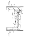
本実施形態のシステムでは、建物の基礎スラブ1と最下階の床2との間に湧水処理層3を設置するとともに、建物の地下外壁4とその周囲地盤との間には湧水処理層3に通じる地下水集水層5を設け、建物周辺地盤の地下水を地下水集水層5により集水して湧水処理層3に導入することを主眼としている。
In the system of the present embodiment, a
具体的には、図示例の場合には地下外壁4の周囲に山留め壁6が設けられていて、その山留め壁6と地下外壁4との間に適宜の排水材パネルや不織布等の透水性材料が介装されることで地下水集水層5が形成されている。
なお、山留め壁6は建物の施工時に仮設的に設けたものを残置してそのまま利用すれば良いが、建物の完成後にはその内側に地下水を流入させるとともに地下水集水層5を保護する機能を要するので、山留め壁6としては地下水の流入を完全には阻止しないような適度の通水機能を有する構造のもの(たとえば親杭横矢板工法による山留め壁のように完全止水壁としては機能しない構造のもの)とすることが好ましい。
但し、山留め壁6は地下水を集水するうえでは必ずしも必要ではなく、地下水集水層5がそれ自体で十分な集水機能を有しかつ格別の保護を必要としないものであれば山留め壁6を撤去しても良いし、山留め壁6を設けずとも地下水集水層5を支障なく形成できる場合には山留め壁6をはじめから省略することでも差し支えない。
Specifically, in the illustrated example, a
The
However, the
また、上記の湧水処理層3は基本的には通常の建物においても湧水を処理するために基礎部に設けられる湧水槽と同様に機能するものであるが、本実施形態では図2に示すように格子状の通水路を有する湧水処理パネルが基礎スラブ1上に設置されることで湧水処理層3が形成されており、その湧水処理パネル上に押さえコンクリートが打設されて最下階の床2が形成されるようになっている。
なお、基礎スラブ1と湧水処理パネルとの間にはたとえばゴムアスファルト系塗膜防水材の塗布等による適宜の防水処理を施すことが好ましい。また、必要であれば上記の地下水集水層5と地下外壁4との間にも同様の防水処理を施せば良い。
The
In addition, it is preferable to perform an appropriate waterproofing treatment between the basic slab 1 and the spring water treatment panel, for example, by applying a rubber asphalt-based coating film waterproofing material. If necessary, the same waterproof treatment may be applied between the
上記の地下水集水層5の下部と湧水処理層3との間には地下外壁4を貫通する地下水導入管7が所定間隔で設置されていて、地下水集水層5に集水された地下水はそれら地下水導入管7を通して湧水処理層3に導入可能とされ、かつ各地下水導入管7の先端部に設けられている調整弁8の開度調整により湧水処理層3への地下水の導入量が調整可能とされている。
Between the lower part of the
湧水処理層3の一角部にはピット9が設けられていて湧水処理層3全体はそのピット9に向かって下がり勾配となるように形成されており、したがって地下水導入管7から湧水処理層3の各所に導入された地下水は図中の矢印で示すようにピット9に向かって自然流下してピット9に貯留されるようになっている。
なお、湧水処理層3からピット9への流入部には越流堰10が設けられていて、その越流堰10の高さの調整により湧水処理層3からピット9への流入量や湧水処理層3内における湧水の水位や滞留時間を適切に調整可能とされている。
A
An
そして、ピット9内にはポンプ11が設置されていて、そのポンプ11により汲み上げた湧水を水質処理装置12を経てヒートポンプ(水熱源ヒートポンプ)13に供給し、ヒートポンプ13は湧水を熱源水として利用して冷房時においては冷水を調製するとともに暖房時においては温水を調製して空調機に供給するようになっている。
なお、上記のヒートポンプ13としては冷暖房用の熱源機のみならず、必要に応じて給湯用その他の用途に供する熱源機も適用できる。
A
In addition, as said
さらに、ヒートポンプ13により熱源水として利用した後の湧水は建物内の各所に中水として供給して雑用水として利用するようになっており、それによる節水効果が得られるものとなっている。なお、そのように熱利用後の湧水を中水として利用するためには、上記の水質処理装置12は湧水を熱源水として利用可能な水質とするばかりでなく中水としても利用可能な水質に調整し得るものとしておく必要がある。
Furthermore, the spring water after being used as the heat source water by the
通常の建物では周囲地盤全体から建物内に無駄に流入してくる湧水を単に排水処理するしかないが、本実施形態の地下水熱利用システムは地下外壁4の外側に敢えて地下水集水層5を設けて建物の周囲地盤から地下水を積極的にかつ効率的に集水して湧水処理層3に導き、その湧水を冷暖房用あるいは他の用途の熱源水として有効に利用することが可能であり、しかもその湧水の水温は年間を通じて15〜18℃程度と安定しているから効率的なヒートポンプ運転が可能であり、極めて有効にして合理的なものである。
In ordinary buildings, the spring water that flows wastefully into the building from the entire surrounding ground can only be drained, but the groundwater heat utilization system of this embodiment dares to place the
特に本発明の地下水熱利用システムは、地下外壁4の外側に適宜の透水性材料を設置することのみで地下水集水層5を低コストで設置可能であるし、湧水処理層3は通常の建物においても不可欠である湧水槽を転用可能であるから、多数の専用の井戸を設けたり多数の杭を利用して地下水との熱交換を行う従来システムに比較してイニシャルコストを十分に軽減することが可能である。
In particular, in the groundwater heat utilization system of the present invention, the
しかも、本発明の地下水熱利用システムでは、地下水導入管7に設けた調整弁8や越流堰10の調整によって所望の湧水量を確保することが可能であり、それにより年間を通じて最適かつ効率的な地下水熱利用が可能であるし、仮に地下水の利用が不要となったり湧水処理層3への湧水の導入を停止する必要が生じた場合には調整弁8を閉じてしまえば必要以上の湧水の流入を阻止できるから、地下水熱利用システムとして極めて合理的あり有効である。
Moreover, in the groundwater heat utilization system of the present invention, it is possible to secure a desired amount of spring water by adjusting the regulating
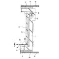
図3〜図4は本発明の地下水熱利用システムの第2実施形態を示すものである。
上記第1実施形態ではピット9に集水した湧水をポンプ11によりヒートポンプ13に供給して熱源水として直接的に利用するものとしたが、本第2実施形態では地下水集水層5内の地下水および湧水処理層3内の湧水との熱交換によりその保有熱エネルギーを間接的に利用するものである。
3 to 4 show a second embodiment of the groundwater heat utilization system of the present invention.
In the first embodiment, the spring water collected in the
具体的には、本第2実施形態では地下水集水層5内および湧水処理層3内に一連の熱交換用配管14を蛇行状態で配管してそれに熱媒体(冷温水あるいはブライン)を循環させることにより、地下水集水層5内を下方に向かって流下する地下水および湧水処理層3内をピット9に向かって流下する湧水と熱媒体との間で熱交換を行いつつ、その熱媒体をヒートポンプ13に供給するようにしたものである。
なお、熱交換用配管14の所要長や熱媒体流量等の諸元は、集水される地下水量やその温度条件等を考慮して所望の熱交換効率が得られるように適切に設定すれば良い。
また、熱交換用配管14は必ずしも図示例のように地下水集水層5内および湧水処理層3内の全体にわたって配管することはなく必要範囲に設置すれば良く、場合によっては地下水集水層5内にのみ設置したり湧水処理層3内にのみ設置することでも良いし、必要に応じて複数系統の熱交換用配管14を適宜のゾーニングを設定して設置すれば良い。
Specifically, in the second embodiment, a series of
In addition, if the specifications such as the required length of the
In addition, the
また、本第2実施形態においても、熱利用後の湧水を最終的には中水として利用するべく、ピット9内の湧水をポンプ11により汲み上げて水質処理装置12を経て建物内各所に供給するようにしており、したがって本第2実施形態においても、第1実施形態の場合と全く同様に、地下水集水層5により積極的に集水して湧水処理層3に導入した湧水を熱源水として有効に利用でき、かつ熱利用後の湧水を中水としても有効に利用可能である。
Also in the second embodiment, the spring water in the
以上で本発明の実施形態について説明したが、本発明は上記各実施形態に限定されるものでは勿論なく、たとえば以下に列挙するような適宜の設計的変更や応用が可能である。 The embodiments of the present invention have been described above. However, the present invention is not limited to the above-described embodiments, and appropriate design changes and applications such as those listed below are possible.
上記第1実施形態ではピット9に集水した湧水を熱源水として直接利用するものとし、第2実施形態ではピット9に流入する前の地下水(湧水)を熱交換により間接利用するようにしたが、地下水の水温や熱源水として必要とされる水温その他の条件によっては双方を組み合わせて併用することも可能である。
In the first embodiment, the spring water collected in the
上記実施形態では熱利用後の湧水をさらに中水として利用するようにしたが、その必要がなければ熱利用後の湧水は適宜排水してしまえば良い。
また、中水として利用する場合において、熱利用後の湧水が中水としての所要量よりも多量である場合には余剰分を排水してしまえば良い。
さらに、地下水の水質が良質であってそれを熱源水や中水として利用するうえで格別の水質処理を行う必要が無ければ、上記実施形態における水質処理装置12は省略可能である。
In the above embodiment, the spring water after use of heat is further used as intermediate water. However, if not necessary, the spring water after use of heat may be drained as appropriate.
Moreover, when using as middle water, when the spring water after heat utilization is larger than the required amount as middle water, the surplus part should just be drained.
Furthermore, the water
上記各実施形態では地下水集水層5と湧水処理層3とを地下水導入管7を介して連通させ、かつ地下水導入管7には調整弁8を設けて導入量を調整可能としたが、その必要がなければ地下水導入管7を省略して地下水集水層5と湧水処理層3とを単に連続的に設けておけば良い。
また、上記各実施形態では湧水処理層3からピット9への流入部に越流堰10を設けたが、越流堰10が不要であれば省略しても良いし、さらに湧水処理層3自体で十分な水深を確保し得て格別のピットを設ける必要がなければ上記実施形態におけるピット9を省略しても差し支えない。
In each of the above embodiments, the
Moreover, in each said embodiment, although the
上記各実施形態のように地下水導入管7に調整弁8を設ける場合、その調整弁8は手動操作により開閉するものでも良い(その場合、地下水導入管7を床下に設けている場合には、調整弁8を操作するための点検口を床2の要所に設けておけば良い)が、調整弁8を電磁弁や電動弁等により構成して遠方操作することが好ましい。その場合、適宜のセンサによって地下水量や地下水温、熱負荷等を検出して地下水集水層5から湧水処理層3への導入量が最適となるように調整弁8を自動制御するようなシステムを付加することも考えられ、それにより最適な自動運転が可能となる。
併せて、上記実施形態のようにピット9への流入量を越流堰10により調整する場合においては、その越流堰10を可動堰としてそれを調整弁8の操作と関連づけてあるいはそれとは独立に自動制御することも好ましい。
When the
In addition, when the inflow amount to the
上記各実施形態のように地下水導入管7および調整弁8は床下に設置することでも良いが、あるいは図5に示すように床上に設置することでも良く、その場合は調整弁8を容易に手動操作することができる。
The
また、地下水に含まれる砂等の固形物が湧水処理層3内に沈澱堆積することも想定されるので、それを防止するために洗浄設備を備えることも好ましい。
その場合、具体的にはたとえば図5に示したように地下水導入管7を床上に配管するとともに、その地下水導入管7に対して洗浄管15をフラッシュ弁16を介して接続しておき、定期的にあるいは必要に応じて調整弁8を閉じてフラッシュ弁16を開いて洗浄水を湧水処理層3内に高圧で噴射させることにより、湧水処理層3内の沈澱堆積物を容易に洗浄除去することができる。
Moreover, since it is assumed that solids, such as sand contained in groundwater, are deposited in the spring
In that case, specifically, as shown in FIG. 5, for example, the
上記各実施形態では格子状の通水路を有する湧水処理パネルを基礎スラブ1上に設置することで湧水処理層3を形成したが、必ずしもそうすることはなく、湧水処理層3は少なくともそこに導入された湧水を熱源水として利用可能なように設ければ良く、その限りにおいて湧水処理層3の形態や構造、設置範囲は任意である。
地下外壁4の外側に設ける地下水集水層5についても、地下水を効率的に集水して湧水処理層3に導入できるものであれば良く、その限りにおいて地下水集水層5の形態や構造、設置範囲は任意である。
In each of the above embodiments, the spring
The
1 基礎スラブ
2 床
3 湧水処理層
4 地下外壁
5 地下水集水層
6 山留め壁
7 地下水導入管
8 調整弁
9 ピット
10 越流堰
11 ポンプ
12 水質処理装置
13 ヒートポンプ(水熱源ヒートポンプ)
14 熱交換用配管
15 洗浄管(洗浄設備)
16 フラッシュ弁(洗浄設備)
DESCRIPTION OF SYMBOLS 1
14 Heat exchange piping 15 Cleaning tube (cleaning equipment)
16 Flush valve (cleaning equipment)
Claims (7)
前記湧水処理層に導入した地下水を該湧水処理層からポンプにより前記水熱源ヒートポンプに供給可能としたことを特徴とする地下水熱利用システム。 The groundwater heat utilization system according to claim 1,
A groundwater heat utilization system characterized in that groundwater introduced into the springwater treatment layer can be supplied from the springwater treatment layer to the water heat source heat pump by a pump.
前記湧水処理層および前記地下水集水層の双方もしくはいずれか一方に、前記水熱源ヒートポンプに供給する熱源水が循環して前記湧水処理層内の湧水および/または前記地下水集水層内の地下水と熱交換を行う熱交換用配管を設置したことを特徴とする地下水熱利用システム。 A groundwater heat utilization system according to claim 1 or 2,
The heat source water supplied to the water heat source heat pump circulates in the spring water treatment layer and / or the ground water catchment layer to circulate the spring water in the spring treatment layer and / or the ground water catchment layer. Groundwater heat utilization system characterized by installing heat exchange pipes that exchange heat with underground water.
前記地下水集水層と前記湧水処理層との間に、前記地下水集水層により集水した地下水を前記湧水処理層に導入するための地下水導入管を設置し、かつ該地下水導入管に、前記地下水集水層から前記湧水処理層への地下水導入量を調整可能な調整弁を設けたことを特徴とする地下水熱利用システム。 A groundwater heat utilization system according to claim 1, 2 or 3,
Between the groundwater catchment layer and the spring treatment layer, a groundwater introduction pipe for introducing the groundwater collected by the groundwater catchment layer into the spring treatment layer is installed, and the groundwater introduction pipe A groundwater heat utilization system comprising an adjustment valve capable of adjusting an amount of groundwater introduced from the groundwater catchment layer to the spring water treatment layer.
前記湧水処理層にピットを設けるとともに該ピットへの地下水流入量を調整する越流堰を設けたことを特徴とする地下水熱利用システム。 The groundwater heat utilization system according to claim 1, 2, 3, or 4,
A groundwater heat utilization system characterized in that a pit is provided in the spring water treatment layer and an overflow weir for adjusting the amount of groundwater flowing into the pit is provided.
前記湧水処理層に導入された湧水を水処理して中水として利用可能としたことを特徴とする地下水熱利用システム。 The groundwater heat utilization system according to claim 1, 2, 3, 4 or 5,
A groundwater heat utilization system characterized in that the spring water introduced into the spring treatment layer is treated with water to be used as intermediate water.
前記湧水処理層に洗浄水を供給して沈澱堆積物を除去する洗浄設備を設けたことを特徴とする地下水熱利用システム。 The groundwater heat utilization system according to claim 1, 2, 3, 4, 5 or 6,
A groundwater heat utilization system comprising a cleaning facility for supplying cleaning water to the spring water treatment layer to remove sediment deposits.
Priority Applications (1)
| Application Number | Priority Date | Filing Date | Title |
|---|---|---|---|
| JP2011114849A JP5892304B2 (en) | 2011-05-23 | 2011-05-23 | Groundwater heat utilization system |
Applications Claiming Priority (1)
| Application Number | Priority Date | Filing Date | Title |
|---|---|---|---|
| JP2011114849A JP5892304B2 (en) | 2011-05-23 | 2011-05-23 | Groundwater heat utilization system |
Publications (2)
| Publication Number | Publication Date |
|---|---|
| JP2012242045A true JP2012242045A (en) | 2012-12-10 |
| JP5892304B2 JP5892304B2 (en) | 2016-03-23 |
Family
ID=47463940
Family Applications (1)
| Application Number | Title | Priority Date | Filing Date |
|---|---|---|---|
| JP2011114849A Expired - Fee Related JP5892304B2 (en) | 2011-05-23 | 2011-05-23 | Groundwater heat utilization system |
Country Status (1)
| Country | Link |
|---|---|
| JP (1) | JP5892304B2 (en) |
Cited By (3)
| Publication number | Priority date | Publication date | Assignee | Title |
|---|---|---|---|---|
| CN104197587A (en) * | 2014-09-18 | 2014-12-10 | 中冶集团武汉勘察研究院有限公司 | Circular foundation pit internal-disturbance buried pipe type underground heat exchange structure and construction method thereof |
| JP5848490B1 (en) * | 2014-02-28 | 2016-01-27 | 中国電力株式会社 | Heat exchange structure of power generation equipment |
| CN113531930A (en) * | 2021-08-02 | 2021-10-22 | 山东省鲁南地质工程勘察院(山东省地勘局第二地质大队) | Underground heat exchange device for exchanging heat by using mine pit water |
Citations (9)
| Publication number | Priority date | Publication date | Assignee | Title |
|---|---|---|---|---|
| JPH04339912A (en) * | 1991-05-16 | 1992-11-26 | Fujita Corp | Disposal method for spring water from landslide protection wall |
| JPH0540487U (en) * | 1991-07-19 | 1993-06-01 | 昭和電工建材株式会社 | Simple double floor structure |
| JPH09151492A (en) * | 1995-11-30 | 1997-06-10 | Fujita Corp | Spring water utilization device |
| JPH10110442A (en) * | 1996-10-07 | 1998-04-28 | Jsp Corp | Spring water draining material for basement, water storage tank and underground wall |
| JPH10121777A (en) * | 1996-10-16 | 1998-05-12 | Taisei Corp | External shielding wall against radiation and construction thereof |
| JP2005351079A (en) * | 2005-08-03 | 2005-12-22 | Sekisui Chem Co Ltd | Water storage device |
| JP2008275263A (en) * | 2007-05-01 | 2008-11-13 | Kajima Corp | Underground heat exchange system |
| JP2009264721A (en) * | 2008-04-23 | 2009-11-12 | Takahashi Kanri:Kk | Earth solar system (single layer type) |
| JP2011007447A (en) * | 2009-06-26 | 2011-01-13 | Ohbayashi Corp | Method of installing underground heat exchanger |
-
2011
- 2011-05-23 JP JP2011114849A patent/JP5892304B2/en not_active Expired - Fee Related
Patent Citations (9)
| Publication number | Priority date | Publication date | Assignee | Title |
|---|---|---|---|---|
| JPH04339912A (en) * | 1991-05-16 | 1992-11-26 | Fujita Corp | Disposal method for spring water from landslide protection wall |
| JPH0540487U (en) * | 1991-07-19 | 1993-06-01 | 昭和電工建材株式会社 | Simple double floor structure |
| JPH09151492A (en) * | 1995-11-30 | 1997-06-10 | Fujita Corp | Spring water utilization device |
| JPH10110442A (en) * | 1996-10-07 | 1998-04-28 | Jsp Corp | Spring water draining material for basement, water storage tank and underground wall |
| JPH10121777A (en) * | 1996-10-16 | 1998-05-12 | Taisei Corp | External shielding wall against radiation and construction thereof |
| JP2005351079A (en) * | 2005-08-03 | 2005-12-22 | Sekisui Chem Co Ltd | Water storage device |
| JP2008275263A (en) * | 2007-05-01 | 2008-11-13 | Kajima Corp | Underground heat exchange system |
| JP2009264721A (en) * | 2008-04-23 | 2009-11-12 | Takahashi Kanri:Kk | Earth solar system (single layer type) |
| JP2011007447A (en) * | 2009-06-26 | 2011-01-13 | Ohbayashi Corp | Method of installing underground heat exchanger |
Cited By (3)
| Publication number | Priority date | Publication date | Assignee | Title |
|---|---|---|---|---|
| JP5848490B1 (en) * | 2014-02-28 | 2016-01-27 | 中国電力株式会社 | Heat exchange structure of power generation equipment |
| CN104197587A (en) * | 2014-09-18 | 2014-12-10 | 中冶集团武汉勘察研究院有限公司 | Circular foundation pit internal-disturbance buried pipe type underground heat exchange structure and construction method thereof |
| CN113531930A (en) * | 2021-08-02 | 2021-10-22 | 山东省鲁南地质工程勘察院(山东省地勘局第二地质大队) | Underground heat exchange device for exchanging heat by using mine pit water |
Also Published As
| Publication number | Publication date |
|---|---|
| JP5892304B2 (en) | 2016-03-23 |
Similar Documents
| Publication | Publication Date | Title |
|---|---|---|
| CN107685072B (en) | Centralized combustion type in-situ thermal desorption restoration method for polluted site | |
| JP5963790B2 (en) | Groundwater circulation type geothermal heat collection system and geothermal use air conditioning or hot water supply system | |
| KR101992308B1 (en) | Geothermal System Using a Single Water Supply System for Smart Farm and Building Cooling and Method for constructing this same | |
| KR101370640B1 (en) | Geothermal system which differ in the depth of the construction of geothermal hole | |
| KR101220531B1 (en) | Geothermal system using circulation underground water | |
| CN102155818B (en) | Low-temperature floor radiation heating and refrigerating system device | |
| Minea | Experimental investigation of the reliability of residential standing column heat pump systems without bleed in cold climates | |
| JP5892304B2 (en) | Groundwater heat utilization system | |
| JP4869145B2 (en) | Underground heat exchange system | |
| JP2016070531A (en) | Underground water heat utilization system with infiltration inlet | |
| JP2015038421A (en) | Air conditioning system | |
| KR20130042127A (en) | Cooling and heating system for greenhouse | |
| KR200371813Y1 (en) | Heating change formation the use of a base rock-subferranean water and heat of the earth | |
| JP2010190435A (en) | Rainwater permeation type underground heat exchange system | |
| KR100904291B1 (en) | Air conditioning system that use underground water and rainwater | |
| JP2016023914A (en) | Multistage type ground water heat utilization system | |
| KR101234014B1 (en) | Polyethylene header for ground heat system | |
| JP6907596B2 (en) | How to use groundwater | |
| KR101220897B1 (en) | equipment for exchanging terrestrial heat | |
| KR101658405B1 (en) | Cooling and heating system with heat pump using discharged ground water | |
| JP4811164B2 (en) | Entrance soil structure | |
| CN202119160U (en) | Low-temperature floor radiation heating and refrigerating system device | |
| KR20080093676A (en) | Utilize subterranean water heat pump source | |
| CN201281402Y (en) | Closed type slag flushing water residual heat heating system | |
| JP2019219159A (en) | Waste hot water heat regenerator and waste hot water heat regeneration system using the same |
Legal Events
| Date | Code | Title | Description |
|---|---|---|---|
| A621 | Written request for application examination |
Free format text: JAPANESE INTERMEDIATE CODE: A621 Effective date: 20140326 |
|
| A977 | Report on retrieval |
Free format text: JAPANESE INTERMEDIATE CODE: A971007 Effective date: 20141119 |
|
| A131 | Notification of reasons for refusal |
Free format text: JAPANESE INTERMEDIATE CODE: A131 Effective date: 20141209 |
|
| A521 | Written amendment |
Free format text: JAPANESE INTERMEDIATE CODE: A523 Effective date: 20150204 |
|
| A131 | Notification of reasons for refusal |
Free format text: JAPANESE INTERMEDIATE CODE: A131 Effective date: 20150707 |
|
| A521 | Written amendment |
Free format text: JAPANESE INTERMEDIATE CODE: A523 Effective date: 20150826 |
|
| TRDD | Decision of grant or rejection written | ||
| A01 | Written decision to grant a patent or to grant a registration (utility model) |
Free format text: JAPANESE INTERMEDIATE CODE: A01 Effective date: 20160112 |
|
| A61 | First payment of annual fees (during grant procedure) |
Free format text: JAPANESE INTERMEDIATE CODE: A61 Effective date: 20160209 |
|
| R150 | Certificate of patent or registration of utility model |
Ref document number: 5892304 Country of ref document: JP Free format text: JAPANESE INTERMEDIATE CODE: R150 |
|
| LAPS | Cancellation because of no payment of annual fees |